EP3795242A1 - Membrane pour la récupération de co2 - Google Patents
Membrane pour la récupération de co2 Download PDFInfo
- Publication number
- EP3795242A1 EP3795242A1 EP20205890.5A EP20205890A EP3795242A1 EP 3795242 A1 EP3795242 A1 EP 3795242A1 EP 20205890 A EP20205890 A EP 20205890A EP 3795242 A1 EP3795242 A1 EP 3795242A1
- Authority
- EP
- European Patent Office
- Prior art keywords
- temperature
- responsive
- electrolyte
- solution
- responsive electrolyte
- Prior art date
- Legal status (The legal status is an assumption and is not a legal conclusion. Google has not performed a legal analysis and makes no representation as to the accuracy of the status listed.)
- Withdrawn
Links
Images


Classifications
-
- B—PERFORMING OPERATIONS; TRANSPORTING
- B01—PHYSICAL OR CHEMICAL PROCESSES OR APPARATUS IN GENERAL
- B01D—SEPARATION
- B01D53/00—Separation of gases or vapours; Recovering vapours of volatile solvents from gases; Chemical or biological purification of waste gases, e.g. engine exhaust gases, smoke, fumes, flue gases, aerosols
- B01D53/34—Chemical or biological purification of waste gases
- B01D53/46—Removing components of defined structure
- B01D53/62—Carbon oxides
-
- B—PERFORMING OPERATIONS; TRANSPORTING
- B01—PHYSICAL OR CHEMICAL PROCESSES OR APPARATUS IN GENERAL
- B01D—SEPARATION
- B01D53/00—Separation of gases or vapours; Recovering vapours of volatile solvents from gases; Chemical or biological purification of waste gases, e.g. engine exhaust gases, smoke, fumes, flue gases, aerosols
- B01D53/14—Separation of gases or vapours; Recovering vapours of volatile solvents from gases; Chemical or biological purification of waste gases, e.g. engine exhaust gases, smoke, fumes, flue gases, aerosols by absorption
- B01D53/1425—Regeneration of liquid absorbents
-
- B—PERFORMING OPERATIONS; TRANSPORTING
- B01—PHYSICAL OR CHEMICAL PROCESSES OR APPARATUS IN GENERAL
- B01D—SEPARATION
- B01D53/00—Separation of gases or vapours; Recovering vapours of volatile solvents from gases; Chemical or biological purification of waste gases, e.g. engine exhaust gases, smoke, fumes, flue gases, aerosols
- B01D53/14—Separation of gases or vapours; Recovering vapours of volatile solvents from gases; Chemical or biological purification of waste gases, e.g. engine exhaust gases, smoke, fumes, flue gases, aerosols by absorption
- B01D53/1456—Removing acid components
- B01D53/1475—Removing carbon dioxide
-
- B—PERFORMING OPERATIONS; TRANSPORTING
- B01—PHYSICAL OR CHEMICAL PROCESSES OR APPARATUS IN GENERAL
- B01D—SEPARATION
- B01D53/00—Separation of gases or vapours; Recovering vapours of volatile solvents from gases; Chemical or biological purification of waste gases, e.g. engine exhaust gases, smoke, fumes, flue gases, aerosols
- B01D53/14—Separation of gases or vapours; Recovering vapours of volatile solvents from gases; Chemical or biological purification of waste gases, e.g. engine exhaust gases, smoke, fumes, flue gases, aerosols by absorption
- B01D53/1493—Selection of liquid materials for use as absorbents
-
- B—PERFORMING OPERATIONS; TRANSPORTING
- B01—PHYSICAL OR CHEMICAL PROCESSES OR APPARATUS IN GENERAL
- B01D—SEPARATION
- B01D53/00—Separation of gases or vapours; Recovering vapours of volatile solvents from gases; Chemical or biological purification of waste gases, e.g. engine exhaust gases, smoke, fumes, flue gases, aerosols
- B01D53/22—Separation of gases or vapours; Recovering vapours of volatile solvents from gases; Chemical or biological purification of waste gases, e.g. engine exhaust gases, smoke, fumes, flue gases, aerosols by diffusion
- B01D53/228—Separation of gases or vapours; Recovering vapours of volatile solvents from gases; Chemical or biological purification of waste gases, e.g. engine exhaust gases, smoke, fumes, flue gases, aerosols by diffusion characterised by specific membranes
-
- B—PERFORMING OPERATIONS; TRANSPORTING
- B01—PHYSICAL OR CHEMICAL PROCESSES OR APPARATUS IN GENERAL
- B01D—SEPARATION
- B01D61/00—Processes of separation using semi-permeable membranes, e.g. dialysis, osmosis or ultrafiltration; Apparatus, accessories or auxiliary operations specially adapted therefor
- B01D61/42—Electrodialysis; Electro-osmosis ; Electro-ultrafiltration; Membrane capacitive deionization
-
- F—MECHANICAL ENGINEERING; LIGHTING; HEATING; WEAPONS; BLASTING
- F03—MACHINES OR ENGINES FOR LIQUIDS; WIND, SPRING, OR WEIGHT MOTORS; PRODUCING MECHANICAL POWER OR A REACTIVE PROPULSIVE THRUST, NOT OTHERWISE PROVIDED FOR
- F03G—SPRING, WEIGHT, INERTIA OR LIKE MOTORS; MECHANICAL-POWER PRODUCING DEVICES OR MECHANISMS, NOT OTHERWISE PROVIDED FOR OR USING ENERGY SOURCES NOT OTHERWISE PROVIDED FOR
- F03G7/00—Mechanical-power-producing mechanisms, not otherwise provided for or using energy sources not otherwise provided for
- F03G7/008—Mechanical-power-producing mechanisms, not otherwise provided for or using energy sources not otherwise provided for characterised by the actuating element
- F03G7/011—Actuators having a material for absorbing or desorbing a gas, e.g. with a fuel cell reaction or a metal hydride
-
- H—ELECTRICITY
- H01—ELECTRIC ELEMENTS
- H01B—CABLES; CONDUCTORS; INSULATORS; SELECTION OF MATERIALS FOR THEIR CONDUCTIVE, INSULATING OR DIELECTRIC PROPERTIES
- H01B1/00—Conductors or conductive bodies characterised by the conductive materials; Selection of materials as conductors
- H01B1/06—Conductors or conductive bodies characterised by the conductive materials; Selection of materials as conductors mainly consisting of other non-metallic substances
- H01B1/12—Conductors or conductive bodies characterised by the conductive materials; Selection of materials as conductors mainly consisting of other non-metallic substances organic substances
- H01B1/122—Ionic conductors
-
- H—ELECTRICITY
- H01—ELECTRIC ELEMENTS
- H01M—PROCESSES OR MEANS, e.g. BATTERIES, FOR THE DIRECT CONVERSION OF CHEMICAL ENERGY INTO ELECTRICAL ENERGY
- H01M8/00—Fuel cells; Manufacture thereof
- H01M8/10—Fuel cells with solid electrolytes
- H01M8/1016—Fuel cells with solid electrolytes characterised by the electrolyte material
- H01M8/1018—Polymeric electrolyte materials
- H01M8/102—Polymeric electrolyte materials characterised by the chemical structure of the main chain of the ion-conducting polymer
-
- B—PERFORMING OPERATIONS; TRANSPORTING
- B01—PHYSICAL OR CHEMICAL PROCESSES OR APPARATUS IN GENERAL
- B01D—SEPARATION
- B01D2325/00—Details relating to properties of membranes
- B01D2325/50—Membrane in gel form
-
- H—ELECTRICITY
- H01—ELECTRIC ELEMENTS
- H01M—PROCESSES OR MEANS, e.g. BATTERIES, FOR THE DIRECT CONVERSION OF CHEMICAL ENERGY INTO ELECTRICAL ENERGY
- H01M2300/00—Electrolytes
- H01M2300/0017—Non-aqueous electrolytes
- H01M2300/0065—Solid electrolytes
- H01M2300/0082—Organic polymers
-
- Y—GENERAL TAGGING OF NEW TECHNOLOGICAL DEVELOPMENTS; GENERAL TAGGING OF CROSS-SECTIONAL TECHNOLOGIES SPANNING OVER SEVERAL SECTIONS OF THE IPC; TECHNICAL SUBJECTS COVERED BY FORMER USPC CROSS-REFERENCE ART COLLECTIONS [XRACs] AND DIGESTS
- Y02—TECHNOLOGIES OR APPLICATIONS FOR MITIGATION OR ADAPTATION AGAINST CLIMATE CHANGE
- Y02C—CAPTURE, STORAGE, SEQUESTRATION OR DISPOSAL OF GREENHOUSE GASES [GHG]
- Y02C20/00—Capture or disposal of greenhouse gases
- Y02C20/40—Capture or disposal of greenhouse gases of CO2
-
- Y—GENERAL TAGGING OF NEW TECHNOLOGICAL DEVELOPMENTS; GENERAL TAGGING OF CROSS-SECTIONAL TECHNOLOGIES SPANNING OVER SEVERAL SECTIONS OF THE IPC; TECHNICAL SUBJECTS COVERED BY FORMER USPC CROSS-REFERENCE ART COLLECTIONS [XRACs] AND DIGESTS
- Y02—TECHNOLOGIES OR APPLICATIONS FOR MITIGATION OR ADAPTATION AGAINST CLIMATE CHANGE
- Y02E—REDUCTION OF GREENHOUSE GAS [GHG] EMISSIONS, RELATED TO ENERGY GENERATION, TRANSMISSION OR DISTRIBUTION
- Y02E60/00—Enabling technologies; Technologies with a potential or indirect contribution to GHG emissions mitigation
- Y02E60/30—Hydrogen technology
- Y02E60/50—Fuel cells
Definitions
- the present invention relates to a system, device, and method for producing an ion concentration gradient which are capable of converting a temperature gradient into chemical energy, electrical energy, and the like, and also to a temperature-responsive electrolyte material.
- surfactants poly(N-substituted acrylamide) derivatives, such as poly(N- isopropylacrylamide), poly(N-substituted methacrylamide) derivatives, copolymers of these, poly(vinyl methyl ether), partly
- Such materials have been utilized as incubation materials, biomaterials such as DDS materials, adsorbents, supports for substance separation, and gelling agents.
- DDS materials biomaterials
- adsorbents such as adsorbents
- supports for substance separation and gelling agents.
- Matrigel (trademark) into which a protein such as collagen has been incorporated
- pluronic registered trademark
- UpCell registered trademark
- Patent Document 1 describes a technique which has an electromotive-force layer constituted of both a polar polymer and a polar low-molecular weight compound contained in the matrix of the polymer and in which charges are generated by means of a temperature difference.
- Patent Document 1 JP-A-2007-173221
- the present invention is to provide a system, device, and method for producing an ion concentration gradient and a temperature-responsive electrolyte material which are utilizable, for example, for efficiently converting heat energy that has been discarded into reusable energy or for efficiently recovering an acid gas, such as carbon dioxide.
- a temperature gradient can be converted to a gradient of ion, such as proton, concentration (potential difference) by utilizing a phenomenon in which the pKa of a temperature-responsive polymer electrolyte that, in response to temperature, undergoes phase transitions changes with temperature.
- the invention has been thus completed.
- the present invention is as follows.
- an ion concentration gradient can be efficiently produced by using a temperature-responsive electrolyte and applying a temperature gradient thereto.
- the invention can be rendered usable for electric power generation and as batteries, etc., by utilizing the produced ion concentration gradient as a potential difference, and can be used, for example, for the recovery of an acid gas, such as carbon dioxide, in which adsorption and release can be repeated.
- the invention is applicable to other uses such as, for example, ion separation, improvements in the efficiency of fuel cells, and other energy conversion.
- the present invention is characterized by using a temperature-responsive electrolyte to produce an ion concentration gradient by means of a temperature gradient.
- the temperature-responsive electrolyte to be used in the invention is not particularly limited so long as the electrolyte changes in ionization as temperature changes. It is, however, preferred that the temperature-responsive electrolyte should be, for example, a polymer.
- examples of the temperature-responsive electrolyte include an electrolyte which has both a polar group and a hydrophobic group in the molecule and which has a functional group capable of releasing an ion in aqueous solutions (i.e., ionizable functional group), such as surfactants, poly(N-isopropylacrylamide), and polypeptides (proteins and peptides).
- aqueous solutions i.e., ionizable functional group
- surfactants poly(N-isopropylacrylamide)
- polypeptides proteins and peptides
- the ionizable functional group may be either an acidic group which releases H + or a basic group which is capable of becoming a positive charge, and can be suitably selected in accordance with purposes of applications of the invention.
- Examples of the acidic group include a sulfuric acid group, carboxylic acid group, phosphoric acid group, and phenolic hydroxyl group.
- Examples of the basic group include an amino group, imidazole group, and pyridyl group.
- Such a temperature-responsive electrolyte may be produced by combining an ionizable functional group, by covalent bonding, with a molecule having both a polar group and a hydrophobic group therein.
- a temperature-responsive electrolyte may be produced by copolymerizing a monomer ingredient having an ionizable group, a monomer ingredient having a polar group, and a monomer ingredient having a hydrophobic group or by copolymerizing a monomer ingredient having an ionizable group and a monomer ingredient having a polar group and a hydrophobic group.
- a molecule having both a polar group and a hydrophobic group therein, such as surfactants, poly(N-isopropylacrylamide), and polypeptides (proteins and peptides), has a temperature responsiveness in which the molecule satisfactorily dissolves or disperses in water at low temperatures but, upon heating to a certain temperature higher, the molecule gathers, shrinks, aggregates, geletes, or precipitates due to hydrophobic interaction.
- the degree of electrolytic dissociation (pKa) of an electrolyte reversibly changes in accordance with the environment (polarity) in which the electrolyte is present and with the distance between the electrolyte molecules.
- sulfuric acid in an aqueous solution which is highly polar, mostly ionizes to have the structures of sulfuric acid anions (anions such as H 2 SO 4 - and SO 4 2- ), which are highly polar.
- an organic solvent is added thereto to lower the polarity of the medium, the degree of electrolytic dissociation decreases and a large proportion of those anions comes to have the structure of sulfuric acid (H 2 SO 4 ), which is lowly polar.
- a (high-molecular weight) molecule which combines those two properties and which has a molecule having both a polar group and a hydrophobic group therein, such as a surfactant, a polypeptide, or poly(N-isopropylacrylamide), and further has an ionizable functional group (electrolyte), i.e., a temperature-responsive electrolyte, is utilized to produce an ion concentration gradient from a temperature difference, and the ion concentration gradient is converted to chemical or electrical energy or otherwise utilized.
- electrolyte i.e., a temperature-responsive electrolyte
- Such a temperature-responsive electrolyte behaves in the following manner.
- the molecules gather, shrink, aggregate, gelate, or precipitate to thereby render the environment surrounding the ions hydrophobic (lowly polar) or render the electrolyte less ionizable due to the reduced distance between the ions.
- the molecules disperse, swell, or dissolve to thereby heighten the polarity of the surrounding environment or prolong the distance between the ions, thereby rendering the electrolyte easily ionizable.
- temperature- responsive electrolytes having an acid functional group capable of becoming a negative charge
- an acid functional group capable of becoming a negative charge
- a base functional group capable of becoming a positive charge
- amine a base
- a temperature-responsive nanoparticulate electrolyte was actually synthesized by copolymerizing acrylic acid, which has a carboxylic acid, and N-isopropylacrylamide, and the pH thereof was measured while changing the temperature. As a result, in cases when the temperature was elevated, the pH abruptly came to increase at a certain temperature ( Fig. 9 ). The pH gradient observed in this measurement reached 0.1 K -1 at the most. According to Nernst's equation, that value of gradient corresponds to tens of mVK -1 . An examination of the nanoparticles for the temperature dependence of particle diameter by the dynamic light scattering method revealed that the nanoparticles come to undergo a phase transition and shrink abruptly, at the temperature at which the pH comes to increase.
- this temperature-responsive electrolyte nanoparticles of a poly(N-isopropylacrylamide) copolymer having a carboxylic acid
- this temperature-responsive electrolyte is in a swollen state at low temperatures so that a large proportion of the carboxylic acid has been ionized, but the electrolyte shrinks as the temperature rises, resulting in a decrease in the degree of ionization of the carboxylic acid.
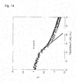
- This phenomenon is observed not only with acidic temperature-responsive electrolytes such as a carboxylic acid but also with basic temperature-responsive electrolytes such as an amine group or an imidazole group ( Figs. 14 , 16 , and 17 ).
- a temperature-responsive nanoparticulate electrolyte was synthesized by copolymerizing a basic monomer having an imidazole group (1-H-imidazole-4-N-acryloylethanamine) or an amine group (N-[3-dimethylamino]propyl)methacrylamide) (DMAPM), in place of acrylic acid, with N-isopropylacrylamide, and examined for temperature-responsive pH change.
- this electrolyte showed relatively high values of pH at temperatures lower than the phase transition point, but as the temperature was elevated, the pH abruptly came to decline at around the phase transition point ( Fig. 14 ).
- the temperature-responsive nanoparticulate electrolyte obtained by copolymerizing N-[3- dimethylamino]propyl]methacrylamide was subjected to pH titration with hydrochloric acid at various temperatures and, as a result, the apparent point of neutralization shifted considerably before and after the phase transition point ( Fig. 17 ). Namely, part of the dimethylamino groups function as a base at temperatures not higher than the phase transition temperature but, at elevated temperatures not below the phase transition temperature, the dimethylamino groups are buried in shrunk polymer chains and do not function as a base.
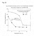
- phase transition temperature of such a temperature-responsive electrolyte can be controlled by means of not only the polarity or ionic strength of the solution containing the temperature-responsive electrolyte or the concentration of the temperature-responsive electrolyte but also the hydrophilic/hydrophobic balance or electrolyte density of the temperature-responsive electrolyte ( Fig. 10 ).
- the pH range or temperature range over which an electrolyte is desired to change can be controlled by controlling the kind of the electrolyte (strong acid, weak acid, weak base, strong base, etc.), the density thereof, or the degree of gathering, shrinkage, aggregation, gelation, or precipitation.
- temperature-responsive electrolytes can be controlled so as to have the desired temperature responsiveness in a range of an extremely low pH to a high pH in accordance with the design of the molecules and the design of the media. For example, as shown in Fig.
- changes in swell ratio with changing temperature can be regulated by regulating the amount of a crosslinkable monomer such as N,N T -methylenebisacrylamide (proportion of a crosslinkable monomer to be copolymerized) when a temperature-responsive electrolyte polymer (nanoparticles) is synthesized.
- a crosslinkable monomer such as N,N T -methylenebisacrylamide (proportion of a crosslinkable monomer to be copolymerized) when a temperature-responsive electrolyte polymer (nanoparticles) is synthesized.
- phase transition temperature can be adjusted by adjusting the content of a hydrophobic monomer such as N-t-butylacrylamide (proportion of a hydrophobic monomer to be copolymerized) when a temperature-responsive electrolyte polymer (nanoparticles) is synthesized.
- a hydrophobic monomer such as N-t-butylacrylamide (proportion of a hydrophobic monomer to be copolymerized) when a temperature-responsive electrolyte polymer (nanoparticles) is synthesized.
- the temperature-responsive electrolyte may be dissolved in water or the like and used in the form of an aqueous solution or the like, or may be used in the form of a solid phase (solid).
- the temperature-responsive electrolyte may be in the state of having been completely dissolved in the aqueous medium or may be present in the state of fine particles in the aqueous medium.
- this temperature-responsive electrolyte is regarded, in the invention, as in the form of an aqueous solution.
- the aqueous solution of the temperature-responsive electrolyte is used in the state of being contained in an adequate vessel.
- Fig.1 diagrammatically shows an example in which an aqueous solution of a temperature-responsive electrolyte having acidic groups is used in the state of being contained in one vessel.
- part of the vessel 1 which contains the aqueous solution of a temperature-responsive electrolyte is adjusted, with a cold source 2, to the phase transition temperature of the temperature-responsive electrolyte or lower, and another part of the vessel 1 is adjusted, with a heat source 3, to the phase transition temperature of the temperature-responsive electrolyte or higher, thereby giving a temperature gradient thereto.
- a plurality of vessels (for example, two vessels) which contain an aqueous solution of a temperature-responsive electrolyte may be used.
- Fig. 2 diagrammatically shows an example in which a plurality of vessels (for example, two vessels) that contain an aqueous solution of a temperature-responsive electrolyte having acidic groups are used.
- a part of a plurality of vessels containing an aqueous solution of a temperature-responsive electrolyte (for example, one of two vessels) is adjusted, with a cold source 2, to the phase transition temperature of the temperature-responsive electrolyte or lower, and another part of the plurality of vessels (for example, the other of the two vessels) is adjusted to the phase transition temperature of the temperature-responsive electrolyte or higher, thereby giving a temperature gradient thereto.
- the aqueous solution has a reduced pH in the vessel 1 cooled with the cold source 2 and has an increased pH in the vessel 1 heated with the heat source 3, thereby producing an ion concentration gradient.
- the device should have a connecting member 4 by which the vessel 1 cooled with the cold source 2 and the vessel 1 heated with the heat source 3 are connected to each other in order that the temperature-responsive electrolyte and ions be capable of moving between the two vessels.
- the connecting member 4 for example, a tube or the like can be used.
- a pH concentration gradient is generated between the solutions although the two solutions are continuous, so long as there is a temperature difference between the solutions.
- two solutions differing in pH can be yielded from one kind of solution.
- a temperature-responsive electrolyte having acidic groups is used to produce a proton (H + ) ion concentration gradient.
- the technique of the invention can be applied not only to the production of a proton (H + ) ion concentration gradient but also production of a gradient of the concentration of various kinds of ions.
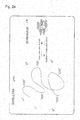
- a temperature-responsive electrolyte in cases when a temperature-responsive electrolyte is added to an aqueous solution of, for example, sodium chloride, sodium iodide, or sodium acetate and a temperature gradient is produced, it is possible to move sodium ions and hydroxide ions to one side and acetic acid ions and protons to the opposite side in a proportion according to the temperature gradient ( Fig. 25 ).
- an aqueous sodium acetate solution for example, can be separated into an aqueous solution having a high acetic acid concentration and an aqueous solution having a high sodium hydroxide concentration, using the temperature gradient as an energy source.
- the inside of the vessel should have been partitioned into a plurality of sections with a semipermeable membrane which is permeable to ions but impermeable to the temperature-responsive electrolyte.
- Fig. 3 diagrammatically shows an example wherein the inside of each vessel containing an aqueous solution of a temperature-responsive electrolyte has been partitioned into a plurality of sections with a semipermeable membrane which is permeable to ions but impermeable to the temperature-responsive electrolyte.
- the use example shown in Fig. 3 is equal to the use example shown in Fig. 2 in the following points: a part of a plurality of vessels containing an aqueous solution of a temperature-responsive electrolyte (for example, one of two vessels) is adjusted, with a cold source 2, to the phase transition temperature of the temperature-responsive electrolyte or lower, and another part of the plurality of vessels (for example, the other of the two vessels) is adjusted to the phase transition temperature of the temperature- responsive electrolyte or higher; and the device has a connecting member 4 by which the vessel 1 cooled with the cold source 2 and the vessel 1 heated with a heat source 3 have been connected to each other.
- the use example shown in Fig. 3 has, besides the feature of the use example shown in Fig. 2 , a feature wherein the inside of each vessel 1 has been partitioned into a plurality of sections with a semipermeable membrane 5 which is permeable to ions but impermeable to the temperature-responsive electrolyte.
- aqueous solution of a temperature-responsive electrolyte in the use example shown in Fig. 3 , is not a solution which contains the temperature-responsive electrolyte only but a solution which further contains sodium acetate.
- two connecting members 4 may be disposed to configure the device so that the solution is moved in one direction through each connecting member 4 by means of a pump 6.
- acetic acid ions and protons can be moved to the vessel 1 cooled with the cold source 2 and sodium ions and hydroxide ions can be moved to the vessel 1 heated with the heat source 3, in a proportion according to the temperature gradient, and the acid and base yielded are continuously separated from the temperature-responsive electrolyte by means of the semipermeable membranes 5.
- Fig. 3 includes two vessels 1 which contain an aqueous solution of a temperature-responsive electrolyte and the vessels 1 each have been partitioned with a semipermeable membrane 5, an example is possible in which only one vessel 1 is included and this vessel 1 has been partitioned with a semipermeable membrane 5.
- Fig. 4 diagrammatically shows one example in which only one vessel 1 that contains an aqueous solution of a temperature-responsive electrolyte is included and this vessel 1 has been partitioned with a semipermeable membrane 5.
- the use example shown in Fig. 4 includes one vessel 1 that contains an aqueous solution of a temperature-responsive electrolyte, the vessel 1 having a horizontally elongated shape, and the inside of the vessel 1 has been divided at the center into two parts with a semipermeable membrane 5 to form two cells.
- This device has a cold source means 21 and a heat source means 31 so that the cold source means 21 covers the outer periphery of a portion of the vessel 1 and that the heat source means 31 covers the outer periphery of another portion of the vessel 1.
- Low-temperature water and high-temperature water are supplied respectively to the cold source means 21 and the heat source means 31 to give a temperature gradient to the entire inside of the vessel 1.
- Fig. 5 diagrammatically shows another example in which only one vessel 1 that contains an aqueous solution of a temperature-responsive electrolyte is included and this vessel 1 has been partitioned with a semipermeable membrane 5.
- the use example shown in Fig. 5 is equal to the use example shown in Fig. 2 in that the use example shown in Fig. 5 has one vessel 1 having a horizontally elongated shape and further has a cold source means 21 and a heat source means 31.
- the use example shown in Fig. 5 has, in a central part thereof, a section formed by partition with two semipermeable membranes 5.
- the solution contained in the vessel 1 is a basic solution.
- the temperature-responsive electrolyte is contained not in the whole of the solution contained in the vessel 1 but in only the central section formed by partition with the two semipermeable membranes 5.
- a temperature-responsive electrolyte is used in the form of a solid phase in the invention includes use of a temperature-responsive electrolyte in the state of a hydrogel.
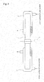
- Fig. 6 diagrammatically shows an example in which a temperature-responsive electrolyte is used in the form of a solid phase.
- the device has a plurality of vessels 1 (for example, two vessels) containing an aqueous salt (KCI or NaCI) solution, and the plurality of (for example, two) vessels 1 are connected with a solid phase of a temperature-responsive electrolyte (referred to also as temperature-responsive solid electrolyte) 11.
- a part of the plurality of vessels 1 (for example, one of the two vessels) is adjusted to the phase transition temperature of the temperature-responsive electrolyte or lower with a cold source 2, and another part of the plurality of vessels 1 (for example, the other of the two vessels) is adjusted to the phase transition temperature of the temperature- responsive electrolyte or higher, thereby giving a temperature gradient.
- the temperature-responsive solid electrolyte 11 may be sandwiched between semipermeable membranes 5.
- the technique of the invention can be applied not only to the production of a proton (H + ) ion concentration gradient but also to production of a gradient of the concentration of any of various ions.
- a temperature-responsive solid electrolyte 11 in cases when a temperature-responsive solid electrolyte 11 is added to an aqueous sodium acetate solution and a temperature gradient is produced, it is possible to move sodium ions and hydroxide ions to one side and acetic acid ions and protons to the opposite side in a proportion according to the temperature gradient. Namely, an aqueous sodium acetate solution can be separated into an aqueous solution having a high acetic acid concentration and an aqueous solution having a high sodium hydroxide concentration, using the temperature gradient as an energy source. Furthermore, the acid and base thus yield can be continuously separated from the temperature-responsive solid electrolyte 11. Consequently, this technique also can be applied as a method for separating a salt solution into a basic solution and an acidic solution, in place of electrolytic processes.
- Embodiments of the invention in which a temperature-responsive solid electrolyte is used include the use example shown in Fig. 5 in which the aqueous solution of a temperature-responsive electrolyte has been replaced with a hydrogel of a temperature-responsive electrolyte, besides the use example shown in Fig. 6 .
- the technique of the invention can be applied to various fields including batteries, recovery of an acid gas such as carbon dioxides, and separation of ions.
- the technique of the invention can be used for heightening the efficiency of thermovoltaic cells or fuel cells by utilizing a potential difference produced by the production of an ion concentration gradient according to the technique.
- a temperature-responsive electrolyte having carboxylic acid groups is used in a fuel cell and a temperature gradient is produced between the electrodes
- a proton concentration gradient is produced between each electrode of the fuel cell and the aqueous solution of the temperature-responsive electrolyte and the electrode reactions on both the positive and the negative electrodes are accelerated as shown in Fig. 26 .
- the efficiency of the fuel cell is heightened.
- Fig. 7 diagrammatically shows an example in which the technique of the invention is applied to a battery.
- one of two vessels 1 containing an aqueous solution of a temperature-responsive electrolyte is adjusted to the phase transition temperature of the temperature-responsive electrolyte or lower with a cold source 2, and the other vessel 1 is adjusted to the phase transition temperature of the temperature-responsive electrolyte or higher.
- two connecting members 4 by which the vessel 1 cooled with the cold source 2 and the vessel 1 heated with a heat source 3 are connected to each other have been disposed to configure the device so that the solution is moved in one direction through each connecting member 4 by means of a pump 6.
- this device has an electrode 7 in each of the vessel 1 cooled with the cold source 2 and the vessel 1 heated with the heat source 3, and these electrodes 7 are electrically connected.
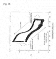
- the solution of a temperature-responsive electrolyte having a basic group is basic and hence readily absorbs carbon dioxide from the gaseous phase.
- the solution becomes neutral or acidic and, hence, the dissolved carbon dioxide can be efficiently recovered ( Fig. 15 ).
- the absorption and recovery of carbon dioxide can be repeatedly conducted by heating or cooling the solution by several degrees centigrade to cause a phase transition ( Fig. 15 ). It is absolutely necessary, for preventing the global warming, to establish a technique for absorbing the carbon dioxide discharged from internal combustion engines.
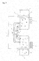
- Fig. 8 diagrammatically shows an example in which the technique of the invention is applied to recovery of carbon dioxide.
- one of two vessels 1 containing an aqueous solution of a temperature-responsive electrolyte having a basic group is adjusted to the phase transition temperature of the temperature-responsive electrolyte or lower with a cold source 2, and the other vessel 1 is adjusted to the phase transition temperature of the temperature-responsive electrolyte or higher.
- two connecting members 4 by which the vessel 1 cooled with the cold source 2 and the vessel 1 heated with a heat source 3 are connected to each other have been disposed to configure the device so that the solution is moved in one direction through each connecting member 4 by means of a pump 6.
- the solution in the vessel 1 cooled with the cold source 2 came to have an elevated pH and became capable of efficiently absorbing carbon dioxide.
- Fig. 8 The use example shown in Fig. 8 is an embodiment in which a temperature- responsive electrolyte having a basic group is used in the state of an aqueous solution.
- a temperature-responsive electrolyte having a basic group is used in the state of an aqueous solution.
- concentration of the electrolyte There are cases where an increase in the electrolyte concentration of the aqueous solution results in an increase in solution viscosity or foaming property to render the recovery of carbon dioxide by a gas-liquid process inefficient.
- This problem concerning solution viscosity or foaming properties can be eliminated by forming a temperature-responsive electrolyte into a solid (gel-state) film, thereby rendering more efficient recovery of carbon dioxide possible.
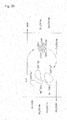
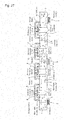
- Still a further possible embodiment of the invention is a multistage ion transportation system such as that shown in Fig. 27 .
- the multistage ion transport system shown in Fig. 27 employs a combination of four kinds of temperature-responsive nanoparticles having different phase transition temperatures and different values of pKa (acidity/basicity).
- An aqueous solution of a temperature-responsive electrolyte which has a phase transition temperature in a low-temperature range and is strongly acidic is circulated between the leftmost vessel 1 in Fig. 27 and the second vessel 1 from the left.
- An aqueous solution of a temperature-responsive electrolyte which has a phase transition temperature in a high-temperature range and is weakly acidic is circulated between the second vessel 1 from the left and the central vessel 1.
- An aqueous solution of a temperature-responsive electrolyte which has a phase transition temperature in a high- temperature range and is weakly basic is circulated between the central vessel 1 and the second vessel 1 from the right.
- An aqueous solution of a temperature-responsive electrolyte which has a phase transition temperature in a low-temperature range and is strongly basic is circulated between the second vessel 1 from the right and the rightmost vessel 1.
- the central vessel 1 is kept at the phase transition temperatures of all temperature-responsive electrolytes or lower, and the leftmost and rightmost vessels 1 are kept at the phase transition temperatures of all temperature-responsive electrolytes or higher.
- the electrolytes are separated from each other by a semipermeable membrane 5 which is a semipermeable membrane (broken line), and protons, hydroxide ions, and low-molecular weight ions only are transported in accordance with a temperature difference between the vessels.
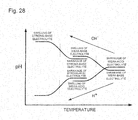
- Fig. 28 is shown a conception of the pH distributions of the temperature- responsive electrolytes present in the vessels 1 within the multistage ion transportation system.
- the broken lines in Fig. 28 indicate the phase transition temperatures of the electrolytes.
- the reaction solution was introduced into a dialysis tube having an MWCO of 10,000 Da and dialyzed for 3 days while repeatedly replacing the water in a large amount, thereby removing the surfactant and unreacted monomers.
- the size (particle diameter) of the electrolyte nanoparticles in this solution was measured by the dynamic light-scattering method. The results of the measurement of the particle diameter of the nanoparticles are shown by the plot of (-o-) in Fig. 9 .
- this solution of electrolyte nanoparticles was diluted 10 times with pure water, and the pH of the dilution was measured in a nitrogen atmosphere. The results of the measurement of the pH of the nanoparticle solution are shown by the plot of (- ⁇ -) in Fig. 9 .
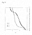
- the temperature-responsive nanoparticles were subjected to ion exchange with a strong cation-exchange resin and then to pH titration at 30°C and 75°C using 0.05 M aqueous NaOH solution. The results thereof are shown in Fig. 11 .
- the results of the titration at 30°C are shown by the plot of (- ⁇ -)
- the results of the titration at 75°C are shown by the plot of (- ⁇ -).
- the apparent point of neutralization has clearly shifted leftward. It was hence understood that the substantial amount of the acid within the solution had decreased due to the shrinkage of the nanoparticles.
- this aqueous solution was subjected to ion exchange with a strong cation-exchange resin, and NaOH was thereafter added thereto in given amounts to adjust the pH of the solution to 5.5, 4.5, and 3.5 at room temperature.
- Each resultant solution was introduced into the vessel 1 of the device shown in Fig. 4 , and the temperatures of the left-hand and right-hand portions were gradually changed.
- the pH in the low-temperature-side portion of the vessel 1 changed little even when the temperature of the high-temperature-side portion was changed.
- the pH responsiveness in the high-temperature-side portion of the vessel 1 changed as shown by each of (a), (b), and (c) in Fig. 12 .
- a semipermeable membrane 5 was disposed between the left-hand and right-hand cells so that the polymer (temperature-responsive electrolyte nanoparticles) did not move and low-molecular weight ions only moved.
- the pH in the high-temperature-side portion of the vessel 1 came to rise abruptly at around the phase transition temperature when the temperature rose.
- the pH in the high-temperature-side portion of the vessel 1 during temperature declining showed the same pH-temperature profile as during the temperature rising.
- this aqueous solution was subjected to ion exchange with a strong anion-exchange resin and then solidified by freeze drying.
- Two milliliters of 1 mM aqueous sodium iodide solution was added to 200 mg of the solid obtained, thereby producing a hydrogel.
- This hydrogel was sandwiched between semipermeable membranes and disposed in the central part of the device shown in Fig. 5 (the part sandwiched between the two semipermeable membranes 5).
- Fifty milliliters of 1-mM aqueous sodium iodide solution was introduced into each of the left-hand and right-hand cells located outside the semipermeable membranes 5.
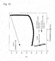
- FIG. 13 is shown the pH responsiveness of the solutions in the high-temperature-side and low-temperature-side cells which was observed when the temperature of the left-hand cell was rapidly elevated to 75°C while keeping the temperature of the right-hand cell constant at 20°C.
- the pH of the solution in the high-temperature-side cell is shown by the plot of (- ⁇ -)
- the pH of the solution in the low-temperature-side cell is shown by the plot of (-o-).
- a semipermeable membrane 5 was disposed between the hydrogel of temperature- responsive electrolyte nanoparticles and each of the left-hand and right-hand cells so that no polymer movement occurred and low-molecular weight ions only moved.
- the acrylamide having an imidazole group as a side chain (1-H-imidazole-4-N-acryloylethanamine) was synthesized by the condensation reaction of histamine with N-(acryloyloxy)succinimide in accordance with Wenhao Liu. et. Al., J. AM. CHEM. SOC., 2010, Vol.132, p.472-483 .
- In 30 mL of ultrapure water were dissolved 985 mg of N-isoprorylacrylamide, 76.4 mg of the I-H-imidazole-4-N-acryloylethanamine, 29 mg of N,N'-methylenebisacrylamide, and 21.9 mg of cetyltrimethylammonium bromide.
- This solution was introduced into a 100-mL eggplant type flask, which was then tightly sealed with a septum.
- the contents were stirred with a magnetic stirrer while being heated at 70°C on an oil bath, until the contents became even.
- two needles were stabbed into the septum to dispose the tip of one needle under the liquid surface and the tip of the other needle over the liquid surface, and nitrogen was externally introduced through the needle under the liquid surface and gently bubbled into the liquid to conduct degassing for 30 minutes.
- a solution prepared by dissolving 21 mg of 2,2 T -azobis(propane-2-carbamidine) dihydrochloride in 0.3 mL of ultrapure water was added to that solution through a needle.
- the needle other than the needle connected to nitrogen was wholly removed, and the contents were reacted at 70°C for 3 hours in a nitrogen atmosphere.
- the septum was opened to thereby terminate the reaction.
- the reaction solution was introduced into a dialysis tube having an MWCO of 10,000 Da and dialyzed for 3 days while repeatedly replacing the water in a large amount, thereby removing the surfactant and unreacted monomers.
- This solution of electrolyte nanoparticles was diluted with pure water so as to result in a nanoparticle concentration of 10 mg/mL, and all anions were removed therefrom with a strong anion-exchange resin. Thereafter, the resultant solution was examined for pH change with changing temperature, while conducting nitrogen bubbling. The results thereof are shown in Fig. 14 . It can be seen from Fig. 14 that the pH declined abruptly after the temperature exceeded the phase transition temperature (30°C).
- N-isoprorylacrylamide and DMAPM were dissolved in 30 mL of methanol in amounts of 95 mol% and 5 mol% respectively (monomer phase concentration, 312 mM).
- This solution was introduced into a 100 mL eggplant type flask, which was then tightly sealed with a septum. Two needles were stabbed into the septum to dispose the tip of one needle under the liquid surface and the tip of the other needle over the liquid surface, and nitrogen was externally introduced through the needle under the liquid surface and gently bubbled into the liquid to conduct degassing for 30 minutes.
- the solution obtained was freeze-dried.
- the polymer obtained was dissolved in water and diluted with pure water so as to result in a concentration of 10 mg/mL, and all anions were removed therefrom with a strong anion-exchange resin.
- the solution having a temperature of 30°C or 75°C was subjected to pH titration with an aqueous hydrochloric acid solution while conducting nitrogen bubbling.
- the results thereof are shown in Fig. 16 .
- the results of the titration of the 30 ⁇ C solution are shown by the plot of (-o-)
- the results of the titration of the 75°C solution are shown by the plot of (- ⁇ -).
- N-isoprorylacrylamide, DMAPM, and N,N'-methylenebisacrylamide were dissolved 21.9 mg of cetyltrimethylammonium bromide.
- This solution was introduced into a 100-mL eggplant type flask, which was then tightly sealed with a septum. The contents were stirred with a magnetic stirrer while being heated at 70°C on an oil bath, until the contents became even.
- the reaction solution was introduced into a dialysis tube having an MWCO of 10,000 Da and dialyzed for 3 days while repeatedly replacing the water in a large amount, thereby removing the surfactant and unreacted monomers.
- This solution of electrolyte nanoparticles was diluted with pure water so as to result in a nanoparticle concentration of 10 mg/mL, and all anions were removed therefrom with a strong anion-exchange resin. Thereafter, the solution having a temperature of 30°C, 45°C, 60°C, or 75°C was subjected to pH titration with an aqueous hydrochloric acid solution while conducting nitrogen bubbling. The results are shown in Fig. 17 . In Fig.
- the results of the titration of the solution at 30°C are shown by the plot of (-o-)
- the results of the titration of the solution at 45°C are shown by the plot of (- ⁇ -)
- the results of the titration of the solution at 60°C are shown by the plot of (- ⁇ -)
- the results of the titration of the solution at 75°C are shown by the plot of (- ⁇ -).
- the abscissa in Fig. 17 indicates the molar amount of HCI used for titration per g of the nanoparticles. It can be seen from Fig. 17 that the apparent pKa declines as the temperature rises. It can also be seen that at the temperatures of 60°C and higher, the apparent point of neutralization appears in two stages, and that at 75°C, the apparent amine amount has reduced to a half or less.
- N-isoprorylacrylamide, DMAPM, and N,N'-methylenebisacrylamide were dissolved 21.9 mg of cetyltrimethylammonium bromide.
- This solution was introduced into a 100-mL eggplant type flask, which was then tightly sealed with a septum. The contents were stirred with a magnetic stirrer while being heated at 70°C on an oil bath, until the contents became even.
- the reaction solution was introduced into a dialysis tube having an MWCO of 10,000 Da and dialyzed for 3 days while repeatedly replacing the water in a large amount, thereby removing the surfactant and unreacted monomers.
- This solution of electrolyte nanoparticles was diluted with pure water so as to result in a nanoparticle concentration of 1 mg/mL, and all anions were removed therefrom with a strong anion-exchange resin. Thereafter, 500 mL of the solution was introduced into a gas washing bottle, and 10% carbon dioxide (90% nitrogen) gas was bubbled thereinto. The solution was saturated with carbon dioxide at 30°C overnight, and the amount of carbon dioxide which was emitted when the solution was heated to 75°C was determined with a gas chromatograph.
- FIG. 19 are plots from which the amounts of carbon dioxide which was emitted/absorbed when similar experiments were conducted using pure water have been subtracted. It was understood from Fig. 18 and Fig. 19 that DMAPM monomer, which is a low-molecular weight compound, emits or absorbs little carbon dioxide, whereas substantially one molecule of carbon dioxide is absorbed in and released from the temperature-responsive nanoparticles per molecule of the amine. The solution was subjected to the carbon dioxide emission/absorption cycle three times, and the emission amounts and absorption amounts in the cycling (per L of the same solution) are shown in Fig. 20 .
- a solution of temperature-responsive electrolyte nanoparticles was prepared in the same manner as in Example 1, dried, and then dissolved in methanol, and this solution was cast on a glass semipermeable membrane. Another semipermeable membrane was superposed thereon to sandwich the cast methanol solution between the semipermeable membranes, and this methanol solution was allowed to dry naturally. Thus, a temperature-responsive electrolyte film was formed between the two semipermeable membranes. The film produced was set in a membrane permeation experiment device such as that shown in Fig. 6 . Aqueous NaCI solutions differing in temperature were brought into contact with the film respectively from both sides thereof, and these aqueous solutions on both sides of the film were examined for pH and ion concentration.
- the low-temperature-side aqueous solution had a reduced pH and an increased hydrogen ion concentration, while the high-temperature-side aqueous solution had an increased pH and a reduced hydroxyl ion concentration.
- NIPAm N-isoprorylacrylamide
- DMAPM aminopropylacrylamide
- APM aminopropylacrylamide
- 1-H-imidazole-4-N-acryloylethanamine 1-H-imidazole-4-N-acryloylethanamine
- This solution was introduced into a 100-mL eggplant type flask, which was then tightly sealed with a septum.
- the contents were stirred with a magnetic stirrer while being heated at 70°C on an oil bath, until the contents became even. After the contents had become even, two needles were stabbed into the septum to dispose the tip of one needle under the liquid surface and the tip of the other needle over the liquid surface, and nitrogen was externally introduced through the needle under the liquid surface and gently bubbled into the liquid to conduct degassing for 30 minutes.
- a solution prepared by dissolving 21 mg of 2,2'-azobis(propane- 2-carbamidine) dihydrochloride in 0.3 mL of ultrapure water was added to that solution through a needle. The needle other than the needle connected to nitrogen was wholly removed, and the contents were reacted at 70°C for 3 hours in a nitrogen atmosphere.
- the septum was opened to thereby terminate the reaction.
- the reaction solution was introduced into a dialysis tube having an MWCO of 10,000 Da and dialyzed for 3 days while repeatedly replacing the water in a large amount, thereby removing the surfactant and unreacted monomers. All anions in the aqueous solution were removed with a strong anion-exchange resin, and the aqueous solution was thereafter dried to obtain a white powder. The white powder was dissolved in methanol. This solution was cast into a U- shaped glass tube and allowed to dry naturally. Thus, a solid temperature-responsive electrolyte film was formed in the glass tube. A given amount of water was added to the film, and 20°C 10% carbon dioxide (90% nitrogen) saturated with water vapor was passed through the glass tube. The temperature of the glass tube was changed between 30°C and 75°C, and the amount of carbon dioxide absorbed or emitted during this operation was determined with a gas chromatograph.
- to adjust the temperature of the glass tube to 30°C is to cause the electrolyte film to absorb carbon dioxide, while to adjust the temperature thereof to 75°C is to cause the electrolyte film to emit the absorbed carbon dioxide.
- a solution of a temperature-responsive polymer electrolyte was synthesized in the same manner as in Example 3 and dried to obtain a white powder.
- the white powder was dissolved in methanol. This solution was cast into a U-shaped glass tube and allowed to dry naturally. Thus, a solid temperature-responsive electrolyte film was formed in the glass tube.
- a given amount of water was added to the film, and 20°C 10% carbon dioxide (90% nitrogen) saturated with water vapor was passed through the glass tube.
- the temperature of the glass tube was changed between 30°C and 75°C, and the amount of carbon dioxide absorbed or emitted during this operation was determined with a gas chromatograph.
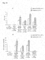
- Films produced in Examples 7 and 8 (the film constituted of nanoparticles containing 5% by mole DMAMP; the film constituted of nanoparticles containing 5% by mole AMP; and the film constituted of a linear polymer containing 5% by mole DMAMP) and films as Reference or Comparative Examples, i.e., a film constituted of nanoparticles of an NIPAm homopolymer, a film constituted of a linear polymer containing 98% by mole DMAMP, and a film to which no water had been added, were examined for carbon dioxide absorption and emission amounts. The results thereof are shown in Fig. 21 .
- (A) shows the volume amount (mL) of carbon dioxide absorbed or emitted per g of each film
- the film having no amine group the film constituted of NIPAm homopolymer nanoparticles
- the film to which no water had been added was used, absorption and emission of carbon dioxide was unable to be ascertained at all.
- the film constituted of a linear polymer containing 98% by mole DMAMP sufficient absorption and emission of carbon dioxide was able to be ascertained but the molar amount of carbon dioxide absorbed or emitted per mole of the amino groups was not large.
- the system, device, and method for producing an ion concentration gradient according to the invention and the temperature-responsive electrolyte material according to the invention can be applied to batteries and the like, recovery of an acid gas, such as carbon dioxide, ion separation, improvements in the efficiency of fuel cells, and other applications including energy conversion.
Landscapes
- Chemical & Material Sciences (AREA)
- Engineering & Computer Science (AREA)
- Chemical Kinetics & Catalysis (AREA)
- Analytical Chemistry (AREA)
- General Chemical & Material Sciences (AREA)
- Oil, Petroleum & Natural Gas (AREA)
- Health & Medical Sciences (AREA)
- Combustion & Propulsion (AREA)
- Water Supply & Treatment (AREA)
- Sustainable Energy (AREA)
- Life Sciences & Earth Sciences (AREA)
- Sustainable Development (AREA)
- Environmental & Geological Engineering (AREA)
- Biomedical Technology (AREA)
- Spectroscopy & Molecular Physics (AREA)
- Physics & Mathematics (AREA)
- Mechanical Engineering (AREA)
- General Engineering & Computer Science (AREA)
- Urology & Nephrology (AREA)
- Manufacturing & Machinery (AREA)
- Crystallography & Structural Chemistry (AREA)
- Electrochemistry (AREA)
- Hybrid Cells (AREA)
- Gas Separation By Absorption (AREA)
- Addition Polymer Or Copolymer, Post-Treatments, Or Chemical Modifications (AREA)
- Treating Waste Gases (AREA)
- Physical Or Chemical Processes And Apparatus (AREA)
- Conductive Materials (AREA)
- Fuel Cell (AREA)
- Separation Using Semi-Permeable Membranes (AREA)
- Carbon And Carbon Compounds (AREA)
Applications Claiming Priority (4)
| Application Number | Priority Date | Filing Date | Title |
|---|---|---|---|
| US201161525421P | 2011-08-19 | 2011-08-19 | |
| US201261646543P | 2012-05-14 | 2012-05-14 | |
| PCT/JP2012/070900 WO2013027668A1 (fr) | 2011-08-19 | 2012-08-17 | Système, dispositif et procédé pour générer un gradient de concentration d'ions, et matériau d'électrolyte répondant à la température |
| EP12826155.9A EP2745930B1 (fr) | 2011-08-19 | 2012-08-17 | Système et procédé pour générer un gradient de concentration d'ions utilisant un matériau d'électrolyte répondant à la température, et utilisation du sytème pour la récupération de gaz acide. |
Related Parent Applications (2)
| Application Number | Title | Priority Date | Filing Date |
|---|---|---|---|
| EP12826155.9A Division-Into EP2745930B1 (fr) | 2011-08-19 | 2012-08-17 | Système et procédé pour générer un gradient de concentration d'ions utilisant un matériau d'électrolyte répondant à la température, et utilisation du sytème pour la récupération de gaz acide. |
| EP12826155.9A Division EP2745930B1 (fr) | 2011-08-19 | 2012-08-17 | Système et procédé pour générer un gradient de concentration d'ions utilisant un matériau d'électrolyte répondant à la température, et utilisation du sytème pour la récupération de gaz acide. |
Publications (1)
| Publication Number | Publication Date |
|---|---|
| EP3795242A1 true EP3795242A1 (fr) | 2021-03-24 |
Family
ID=47746411
Family Applications (2)
| Application Number | Title | Priority Date | Filing Date |
|---|---|---|---|
| EP20205890.5A Withdrawn EP3795242A1 (fr) | 2011-08-19 | 2012-08-17 | Membrane pour la récupération de co2 |
| EP12826155.9A Active EP2745930B1 (fr) | 2011-08-19 | 2012-08-17 | Système et procédé pour générer un gradient de concentration d'ions utilisant un matériau d'électrolyte répondant à la température, et utilisation du sytème pour la récupération de gaz acide. |
Family Applications After (1)
| Application Number | Title | Priority Date | Filing Date |
|---|---|---|---|
| EP12826155.9A Active EP2745930B1 (fr) | 2011-08-19 | 2012-08-17 | Système et procédé pour générer un gradient de concentration d'ions utilisant un matériau d'électrolyte répondant à la température, et utilisation du sytème pour la récupération de gaz acide. |
Country Status (4)
| Country | Link |
|---|---|
| US (3) | US10137409B2 (fr) |
| EP (2) | EP3795242A1 (fr) |
| JP (5) | JP6203635B2 (fr) |
| WO (1) | WO2013027668A1 (fr) |
Families Citing this family (17)
| Publication number | Priority date | Publication date | Assignee | Title |
|---|---|---|---|---|
| EP3795242A1 (fr) | 2011-08-19 | 2021-03-24 | Kyushu University, National University Corporation | Membrane pour la récupération de co2 |
| KR20150129026A (ko) | 2013-03-15 | 2015-11-18 | 카본오로 비.브이. | 열반응성 코폴리머를 이용하는 co₂ 함유 가스 스트림으로부터 co₂의 포획 방법 |
| EP3181223A4 (fr) | 2014-08-15 | 2018-04-18 | Kyushu University, National University Corporation | Matériau d'absorption de gaz, utilisation de celui-ci pour l'absorption de gaz, corps d'absorption de gaz, procédé d'absorption de gaz, dispositif d'absorption de gaz acide, dispositif de récupération de gaz acide, dispositif d'absorption de vapeur d'eau, dispositif de récupération de vapeur d'eau, échangeur de chaleur, et dispositif de récupération de chaleur |
| JP6426503B2 (ja) * | 2015-03-09 | 2018-11-21 | 株式会社日立製作所 | 吸着材、それを用いた分離精製装置及び分離精製方法 |
| JP7122752B2 (ja) | 2016-02-25 | 2022-08-22 | 国立大学法人九州大学 | 単層膜、複合体、ガス分離材、フィルター、ガス分離装置および複合体の製造方法 |
| US11239513B2 (en) * | 2016-08-12 | 2022-02-01 | Johnson Ip Holding, Llc | Thermo-electrochemical converter |
| JP6847446B2 (ja) * | 2017-02-17 | 2021-03-24 | 国立大学法人九州大学 | 電解液および発電装置 |
| EP3584866B1 (fr) | 2017-02-17 | 2023-12-13 | Kyushu University, National University Corporation | Solution électrolytique, solution aqueuse électrolytique, et dispositifs de génération d'énergie |
| WO2020124096A2 (fr) * | 2018-12-14 | 2020-06-18 | The Penn State Research Foundation | Procédés pour déterminer la thermodynamique et la cinétique de séparation de phase colloïdale sur un dispositif à gradient de température |
| US20230192928A1 (en) * | 2019-05-21 | 2023-06-22 | Kyushu University, National University Corporation | Polymer material and method for producing same, gas-absorbing material, and gas recovery device |
| JP7531969B2 (ja) | 2020-08-20 | 2024-08-13 | エルジー エナジー ソリューション リミテッド | 熱変色高分子を含む単位セル及びこれを用いた欠陥検出方法 |
| JPWO2023080204A1 (fr) | 2021-11-04 | 2023-05-11 | ||
| JP7795083B2 (ja) * | 2022-01-19 | 2026-01-07 | 横浜ゴム株式会社 | 架橋物 |
| JP2023114144A (ja) * | 2022-02-04 | 2023-08-17 | 横浜ゴム株式会社 | タイヤ用ゴム組成物、及び、タイヤ |
| AU2024271627A1 (en) | 2023-05-15 | 2025-11-20 | Jccl, Inc. | Gas recovery device and gas recovery method |
| CN117735657A (zh) * | 2024-02-20 | 2024-03-22 | 山西天和盛膜技术有限公司 | 一种用于光催化的过滤膜 |
| WO2025245558A1 (fr) * | 2024-05-31 | 2025-12-04 | The University Of Queensland | Procédés et ensembles de séparation d'ions et leurs utilisations |
Citations (3)
| Publication number | Priority date | Publication date | Assignee | Title |
|---|---|---|---|---|
| WO1996015027A1 (fr) * | 1994-11-15 | 1996-05-23 | W.L. Gore & Associates, Inc. | Recipient avec adsorbeur de gaz permettant de respirer en circuit ferme |
| JP2007173221A (ja) | 2005-11-24 | 2007-07-05 | As R&D合同会社 | 発電デバイス、それを用いた発電装置、センサー並びに発熱体 |
| US20110138999A1 (en) * | 2009-12-15 | 2011-06-16 | Uop Llc | Metal organic framework polymer mixed matrix membranes |
Family Cites Families (39)
| Publication number | Priority date | Publication date | Assignee | Title |
|---|---|---|---|---|
| JPS60168706A (ja) | 1984-02-14 | 1985-09-02 | Mitsui Toatsu Chem Inc | 感温性共重合体 |
| JPS60233182A (ja) | 1984-05-07 | 1985-11-19 | Mitsui Toatsu Chem Inc | 重合体エマルシヨンの製造方法 |
| JP3237113B2 (ja) * | 1989-11-06 | 2001-12-10 | 栗田工業株式会社 | ガス吸収液の処理方法 |
| JP3135340B2 (ja) | 1992-02-25 | 2001-02-13 | 森 有一 | ドラッグキャリアー |
| JPH06157689A (ja) * | 1992-11-19 | 1994-06-07 | Nippon Oil & Fats Co Ltd | 熱応答性高分子ゲル、熱応答性高分子ゲル膜及びその製造法 |
| JPH10506132A (ja) | 1994-08-19 | 1998-06-16 | ジェル・サイエンシィズ・インコーポレーテッド | 環境から目標物質を選択的に除去するための応答性ゲル及びその方法 |
| JP3689897B2 (ja) | 1995-12-04 | 2005-08-31 | Jsr株式会社 | 核酸吸着剤 |
| JP2004089211A (ja) | 1997-06-30 | 2004-03-25 | Mebiol Kk | 感温性発熱体 |
| RU2191621C2 (ru) | 1998-04-06 | 2002-10-27 | Ниппон Ниюказаи Ко., Лтд. | Способ регенерации жидкости, абсорбирующей кислый газ, содержащей метилдиэтаноламин и производное пиперазина низших алкилов |
| JP3101714B1 (ja) | 1999-05-11 | 2000-10-23 | 工業技術院長 | 可逆的な親水性−疎水性変化を示す共重合体及びその製造方法 |
| JP2001232104A (ja) | 2000-02-28 | 2001-08-28 | Ebara Corp | 懸濁液の固液分離方法 |
| JP3513479B2 (ja) * | 2000-10-19 | 2004-03-31 | 独立行政法人産業技術総合研究所 | 高温低粘度低温高粘度型感温性高分子材料 |
| JP3502907B2 (ja) * | 2000-11-01 | 2004-03-02 | 独立行政法人産業技術総合研究所 | 側鎖にアミノ酸残基を有する重合体及びその架橋体 |
| JP3921974B2 (ja) | 2001-08-08 | 2007-05-30 | 富士ゼロックス株式会社 | 高分子ゲル組成物、及びそれを用いた光学素子 |
| JP2004043749A (ja) | 2002-07-12 | 2004-02-12 | Mebiol Kk | ハイドロゲル、ゲル体および物質の拡散制御方法 |
| JP2004143301A (ja) * | 2002-10-24 | 2004-05-20 | Asahi Kasei Chemicals Corp | エマルジョン及びそれを用いた塗工液、記録媒体 |
| JP4231735B2 (ja) | 2003-02-04 | 2009-03-04 | 新日本製鐵株式会社 | 二酸化炭素の分離回収方法および装置 |
| JP4426199B2 (ja) * | 2003-03-31 | 2010-03-03 | 独立行政法人産業技術総合研究所 | 感熱性樹脂材料の精製方法 |
| JP2004331760A (ja) | 2003-05-06 | 2004-11-25 | Nippon Chem Ind Co Ltd | 球状感温性樹脂、これを用いた吸着剤及びイオン交換樹脂 |
| JP3855060B2 (ja) * | 2003-08-21 | 2006-12-06 | 独立行政法人産業技術総合研究所 | 熱センサー及びpHセンサー |
| JP4343002B2 (ja) | 2004-03-31 | 2009-10-14 | 花王株式会社 | 感温性ゲル複合物 |
| EP1912724A2 (fr) | 2005-07-28 | 2008-04-23 | Global Research Technologies, LLC | Elimination de dioxyde de carbone dans l'air |
| US20080127632A1 (en) * | 2006-11-30 | 2008-06-05 | General Electric Company | Carbon dioxide capture systems and methods |
| JP2009057522A (ja) | 2007-09-03 | 2009-03-19 | Univ Of Yamanashi | 温度応答性高分子、およびこれを用いた温度応答性ファイバーおよび不織布、並びにその製造方法 |
| MX2010004447A (es) * | 2007-11-20 | 2010-05-13 | Global Res Technologies Llc | Colector de aire con membrana de intercambio ionico funcional para capturar co2 del ambinete. |
| US8017227B2 (en) * | 2008-03-03 | 2011-09-13 | Parviz Soroushian | Adaptive composite materials |
| AU2008221604B2 (en) * | 2008-09-22 | 2010-04-22 | Commonwealth Scientific And Industrial Research Organisation | Temperature-responsive polymer particles in protein separation applications |
| JP5238487B2 (ja) * | 2008-12-26 | 2013-07-17 | 株式会社東芝 | 炭酸ガス回収剤及び炭酸ガス回収方法 |
| EP2228118A1 (fr) | 2009-02-25 | 2010-09-15 | Siemens Aktiengesellschaft | Liquide absorbeur, procédé de fabrication d'un liquide absorbeur, ainsi qu'utilisation d'un liquide absorbeur |
| GB0908372D0 (en) | 2009-05-15 | 2009-06-24 | Univ Manchester | Temperature-responsive co-polymers and uses thereof |
| JP2010274252A (ja) * | 2009-05-27 | 2010-12-09 | Hirotake Katayama | 温度応答性高分子使用した水性二相抽出により、海水中の塩分を抽出除去することを基本にした、海水淡水化プロセス |
| JP5398383B2 (ja) | 2009-06-30 | 2014-01-29 | 一般財団法人川村理化学研究所 | 有機無機複合体粒子、その製造方法および有機無機複合体ヒドロゲル粒子の製造方法 |
| EP2461894B1 (fr) * | 2009-08-04 | 2017-06-14 | CO2 Solutions Inc. | Procédé de capture de co2 à l'aide de microparticules comportant des biocatalyseurs |
| JP5700668B2 (ja) * | 2010-07-01 | 2015-04-15 | 旭化成株式会社 | 二酸化炭素吸収用ポリマー、該ポリマーを利用した二酸化炭素の分離回収方法 |
| JP2012179584A (ja) * | 2011-03-03 | 2012-09-20 | Nitto Boseki Co Ltd | Co2吸収材及びその製造方法 |
| JP2014522298A (ja) * | 2011-05-17 | 2014-09-04 | エンベリッド システムズ, インコーポレイテッド | 屋内空気からの二酸化炭素の低減のための収着剤 |
| US20140106440A1 (en) * | 2011-06-10 | 2014-04-17 | Co2 Solutions Inc. | Enhanced enzymatic co2 capture techniques according to solution pka, temperature and/or enzyme character |
| JP5688335B2 (ja) * | 2011-07-04 | 2015-03-25 | 旭化成株式会社 | 二酸化炭素吸収剤及び該吸収剤を用いた二酸化炭素の分離回収方法 |
| EP3795242A1 (fr) | 2011-08-19 | 2021-03-24 | Kyushu University, National University Corporation | Membrane pour la récupération de co2 |
-
2012
- 2012-08-17 EP EP20205890.5A patent/EP3795242A1/fr not_active Withdrawn
- 2012-08-17 WO PCT/JP2012/070900 patent/WO2013027668A1/fr not_active Ceased
- 2012-08-17 EP EP12826155.9A patent/EP2745930B1/fr active Active
- 2012-08-17 JP JP2013529997A patent/JP6203635B2/ja active Active
- 2012-08-17 US US14/239,283 patent/US10137409B2/en active Active
-
2017
- 2017-08-30 JP JP2017165950A patent/JP6507204B2/ja active Active
-
2018
- 2018-10-16 US US16/161,717 patent/US10300432B2/en active Active
-
2019
- 2019-04-01 JP JP2019069718A patent/JP7028459B2/ja active Active
- 2019-04-16 US US16/385,091 patent/US10695714B2/en active Active
-
2020
- 2020-10-19 JP JP2020175455A patent/JP7108322B2/ja active Active
-
2022
- 2022-07-08 JP JP2022110403A patent/JP2022140462A/ja active Pending
Patent Citations (3)
| Publication number | Priority date | Publication date | Assignee | Title |
|---|---|---|---|---|
| WO1996015027A1 (fr) * | 1994-11-15 | 1996-05-23 | W.L. Gore & Associates, Inc. | Recipient avec adsorbeur de gaz permettant de respirer en circuit ferme |
| JP2007173221A (ja) | 2005-11-24 | 2007-07-05 | As R&D合同会社 | 発電デバイス、それを用いた発電装置、センサー並びに発熱体 |
| US20110138999A1 (en) * | 2009-12-15 | 2011-06-16 | Uop Llc | Metal organic framework polymer mixed matrix membranes |
Non-Patent Citations (1)
| Title |
|---|
| WENHAO LIU, J. AM. CHEM. SOC., vol. 132, 2010, pages 472 - 483 |
Also Published As
| Publication number | Publication date |
|---|---|
| JP6507204B2 (ja) | 2019-04-24 |
| EP2745930A1 (fr) | 2014-06-25 |
| EP2745930B1 (fr) | 2020-12-23 |
| JP6203635B2 (ja) | 2017-09-27 |
| JP2021035676A (ja) | 2021-03-04 |
| JP2022140462A (ja) | 2022-09-26 |
| JPWO2013027668A1 (ja) | 2015-03-19 |
| US10695714B2 (en) | 2020-06-30 |
| EP2745930A4 (fr) | 2015-08-05 |
| JP7108322B2 (ja) | 2022-07-28 |
| JP2018046001A (ja) | 2018-03-22 |
| JP2019153589A (ja) | 2019-09-12 |
| US20190240617A1 (en) | 2019-08-08 |
| WO2013027668A1 (fr) | 2013-02-28 |
| US10300432B2 (en) | 2019-05-28 |
| JP7028459B2 (ja) | 2022-03-02 |
| US20190070555A1 (en) | 2019-03-07 |
| US20140294707A1 (en) | 2014-10-02 |
| US10137409B2 (en) | 2018-11-27 |
Similar Documents
| Publication | Publication Date | Title |
|---|---|---|
| US10695714B2 (en) | System, device, and method for producing ion concentration gradient, and temperature-responsive electrolyte material | |
| Alashkar et al. | A critical review on the use of ionic liquids in proton exchange membrane fuel cells | |
| Hu et al. | A highly stable membrane with hierarchical structure for wide pH range flow batteries | |
| KR20040047809A (ko) | 친수성 중합체 및 전기화학 전지에서의 용도 | |
| Guo et al. | Rational design of thermocells driven by the volume phase transition of hydrogel nanoparticles | |
| Bengui et al. | High performance positively charged membranes with selective swelling-induced ion transport channels for vanadium flow battery application | |
| Qin et al. | Incorporation of H3PO4 into three-dimensional polyacrylamide-graft-starch hydrogel frameworks for robust high-temperature proton exchange membrane fuel cells | |
| Gaur et al. | Ion transfer channel network formed by flower and rod shape crystals of hair hydrolysate in poly (vinyl alcohol) matrix and its application as anion exchange membrane in fuel cells | |
| JPH0830276B2 (ja) | 固体電解質材料,その製造法及びその電気化学的な用途 | |
| CN102956910B (zh) | 水凝胶基中高温质子交换膜及其制备方法和应用 | |
| Oliveira et al. | Preparation and characterization of crosslinked PVAL membranes loaded with boehmite nanoparticles for fuel cell applications | |
| Luo et al. | Modulating the internal porosity of organogel electrolyte via pore-forming agent for low temperature resistant and flexible quasi-solid supercapacitors | |
| Mandanipour et al. | Fabrication and Characterization of a Conductive Proton Exchange Membrane Based on Sulfonated Polystyrenedivinylbenzene Resin-Polyethylene (SPSDR-PE): Application in Direct Methanol Fuel Cells | |
| CN101798394B (zh) | 一种磷酸掺杂的具有自组装结构的磺酸化聚合物复合膜的制备方法 | |
| CN103551147B (zh) | 一种快速、可控的PtBi金属间化合物电催化剂的合成方法 | |
| Yang et al. | Preparation and characterization of directional conducting and lower methanol permeable ultrathin membrane based on poly (vinyl alcohol) and imidazolium compounds | |
| JP6847446B2 (ja) | 電解液および発電装置 | |
| WO2018151098A1 (fr) | Solution électrolytique, solution aqueuse électrolytique et dispositif de génération d'énergie | |
| CN105481732B (zh) | 一种基于内盐的三组分低共熔离子液体 | |
| JP2018133318A (ja) | 電解質水溶液および発電装置 | |
| Wang et al. | High-Capacity and High-Stability Electrochemical CO2 Capture Cell with Coupled Electricity Storage | |
| CN108039498B (zh) | 一种聚苯乙炔修饰燃料电池质子交换膜的改性方法 | |
| JP2007042532A (ja) | 液状電解質 | |
| Han et al. | Cationic Covalent Organic Framework‐Based Membranes for High‐Performance Zn/Br2 Redox Flow Batteries | |
| CN104345080B (zh) | 电化学一氧化碳气体传感器电极的制备方法 |
Legal Events
| Date | Code | Title | Description |
|---|---|---|---|
| PUAI | Public reference made under article 153(3) epc to a published international application that has entered the european phase |
Free format text: ORIGINAL CODE: 0009012 |
|
| STAA | Information on the status of an ep patent application or granted ep patent |
Free format text: STATUS: REQUEST FOR EXAMINATION WAS MADE |
|
| 17P | Request for examination filed |
Effective date: 20201105 |
|
| AC | Divisional application: reference to earlier application |
Ref document number: 2745930 Country of ref document: EP Kind code of ref document: P |
|
| AK | Designated contracting states |
Kind code of ref document: A1 Designated state(s): AL AT BE BG CH CY CZ DE DK EE ES FI FR GB GR HR HU IE IS IT LI LT LU LV MC MK MT NL NO PL PT RO RS SE SI SK SM TR |
|
| RAP1 | Party data changed (applicant data changed or rights of an application transferred) |
Owner name: JCCL, INC. |
|
| STAA | Information on the status of an ep patent application or granted ep patent |
Free format text: STATUS: EXAMINATION IS IN PROGRESS |
|
| 17Q | First examination report despatched |
Effective date: 20240701 |
|
| STAA | Information on the status of an ep patent application or granted ep patent |
Free format text: STATUS: THE APPLICATION HAS BEEN WITHDRAWN |
|
| 18W | Application withdrawn |
Effective date: 20250707 |