EP3795366A1 - Vorrichtung zum robotergestützten drucken von einzeln hergestellten büchern, und entsprechendes verfahren - Google Patents
Vorrichtung zum robotergestützten drucken von einzeln hergestellten büchern, und entsprechendes verfahren Download PDFInfo
- Publication number
- EP3795366A1 EP3795366A1 EP20205537.2A EP20205537A EP3795366A1 EP 3795366 A1 EP3795366 A1 EP 3795366A1 EP 20205537 A EP20205537 A EP 20205537A EP 3795366 A1 EP3795366 A1 EP 3795366A1
- Authority
- EP
- European Patent Office
- Prior art keywords
- corpus
- station
- cover
- book
- poste
- Prior art date
- Legal status (The legal status is an assumption and is not a legal conclusion. Google has not performed a legal analysis and makes no representation as to the accuracy of the status listed.)
- Granted
Links
Images







Classifications
-
- B—PERFORMING OPERATIONS; TRANSPORTING
- B42—BOOKBINDING; ALBUMS; FILES; SPECIAL PRINTED MATTER
- B42C—BOOKBINDING
- B42C19/00—Multi-step processes for making books
- B42C19/08—Conveying between operating stations in machines
-
- B—PERFORMING OPERATIONS; TRANSPORTING
- B26—HAND CUTTING TOOLS; CUTTING; SEVERING
- B26D—CUTTING; DETAILS COMMON TO MACHINES FOR PERFORATING, PUNCHING, CUTTING-OUT, STAMPING-OUT OR SEVERING
- B26D7/00—Details of apparatus for cutting, cutting-out, stamping-out, punching, perforating, or severing by means other than cutting
-
- B—PERFORMING OPERATIONS; TRANSPORTING
- B26—HAND CUTTING TOOLS; CUTTING; SEVERING
- B26D—CUTTING; DETAILS COMMON TO MACHINES FOR PERFORATING, PUNCHING, CUTTING-OUT, STAMPING-OUT OR SEVERING
- B26D7/00—Details of apparatus for cutting, cutting-out, stamping-out, punching, perforating, or severing by means other than cutting
- B26D7/06—Arrangements for feeding or delivering work of other than sheet, web, or filamentary form
-
- B—PERFORMING OPERATIONS; TRANSPORTING
- B42—BOOKBINDING; ALBUMS; FILES; SPECIAL PRINTED MATTER
- B42C—BOOKBINDING
- B42C11/00—Casing-in
- B42C11/04—Machines or equipment for casing-in or applying covers to books
-
- B—PERFORMING OPERATIONS; TRANSPORTING
- B42—BOOKBINDING; ALBUMS; FILES; SPECIAL PRINTED MATTER
- B42C—BOOKBINDING
- B42C5/00—Preparing the edges or backs of leaves or signatures for binding
- B42C5/04—Preparing the edges or backs of leaves or signatures for binding by notching or roughening
-
- B—PERFORMING OPERATIONS; TRANSPORTING
- B42—BOOKBINDING; ALBUMS; FILES; SPECIAL PRINTED MATTER
- B42C—BOOKBINDING
- B42C7/00—Manufacturing bookbinding cases or covers of books or loose-leaf binders
- B42C7/005—Creasing the back of covers
-
- B—PERFORMING OPERATIONS; TRANSPORTING
- B42—BOOKBINDING; ALBUMS; FILES; SPECIAL PRINTED MATTER
- B42C—BOOKBINDING
- B42C9/00—Applying glue or adhesive peculiar to bookbinding
-
- B—PERFORMING OPERATIONS; TRANSPORTING
- B42—BOOKBINDING; ALBUMS; FILES; SPECIAL PRINTED MATTER
- B42C—BOOKBINDING
- B42C9/00—Applying glue or adhesive peculiar to bookbinding
- B42C9/0056—Applying glue or adhesive peculiar to bookbinding applying tape or covers precoated with adhesive to a stack of sheets
-
- B—PERFORMING OPERATIONS; TRANSPORTING
- B25—HAND TOOLS; PORTABLE POWER-DRIVEN TOOLS; MANIPULATORS
- B25J—MANIPULATORS; CHAMBERS PROVIDED WITH MANIPULATION DEVICES
- B25J11/00—Manipulators not otherwise provided for
-
- B—PERFORMING OPERATIONS; TRANSPORTING
- B26—HAND CUTTING TOOLS; CUTTING; SEVERING
- B26D—CUTTING; DETAILS COMMON TO MACHINES FOR PERFORATING, PUNCHING, CUTTING-OUT, STAMPING-OUT OR SEVERING
- B26D7/00—Details of apparatus for cutting, cutting-out, stamping-out, punching, perforating, or severing by means other than cutting
- B26D2007/0012—Details, accessories or auxiliary or special operations not otherwise provided for
- B26D2007/0081—Cutting on three sides, e.g. trilateral trimming
Definitions
- the present invention relates to a device for printing books. It also relates to a method of printing books.
- the invention typically allows a user to print a book on demand, preferably in one copy.
- the document WO 01/56 794 A1 describes a paperback finishing apparatus.
- the document WO99 / 38707 describes an apparatus for binding a book.
- the aim of the present invention is to solve at least one of these aforementioned problems.
- the device according to the invention is preferably arranged to deposit glue on a bonding area of the cover (preferably on the back of the cover), preferably inside the binding station, before assembly or nesting by gluing of the cover on the corpus forming a book.
- the heating position is preferably offset from the deposition position along an offset direction and / or the pre-assembly position is preferably offset from the heating position along this offset direction.
- the binding station preferably comprises locking means arranged to immobilize the cover in the deposit position and / or in the heating position.
- the cover is preferably located in the same plane called the bonding plane for these positions of deposition, heating and / or pre-assembly.
- the binding station is preferably arranged and / or programmed to position the cover in an assembly position offset from the pre-assembly position at least partially perpendicular to the direction of offset so as to assemble or nest the cover and the corpus by collage.
- the binding station preferably comprises a corpus receptacle arranged to receive the corpus in a receiving position.
- the conveying means are preferably arranged and / or programmed so that in the deposit position the gluing zone is not located under the corpus receptacle of the binding station and / or so that in the pre-assembly position the gluing area is located under the corpus receptacle of the binding station.
- the corpus In its reception position, the corpus preferably extends perpendicularly or substantially perpendicular to the cover in its pre-assembly position and / or in its assembly position.
- the conveying means are preferably arranged and / or programmed to take the book out of the binding station perpendicular or substantially perpendicular to the direction of shift and / or by touching only the corpus.
- the device according to the invention preferably comprises a creasing station designed to crease or pre-fold the cover along several parallel fold lines (preferably on the back of the cover), extending over a whole width or length. of the cover, preferably along two or four parallel fold lines, the conveying means being arranged and / or programmed to insert the cover into the creasing station in a creasing position.
- the deposition position is preferably offset from the creasing position along the offset direction.
- the crease position preferably intersects the deposit position.
- the cover In its creasing position, the cover preferably extends perpendicularly or substantially perpendicular to the cover in its deposit position.
- the conveying means preferably comprise a robotic arm provided with fingers arranged and / or programmed to manipulate the cover and / or the corpus.
- the device according to the invention preferably comprises means for measuring or determining a thickness of the corpus.
- the device according to the invention is preferably arranged and / or programmed to determine and then deposit a quantity of glue on the gluing zone of the cover inside the binding station, this quantity of glue being a function of the thickness. measured or determined from the back of the corpus.
- the cover printing or receiving station and the corpus printing or receiving station preferably comprise a printer common to these two stations.
- the device according to the invention preferably comprises a crating station.
- the conveying means are preferably arranged and / or programmed to convey the corpus from the corpus printing or reception station and to the crating station and / or from the crating station to the binding station.
- the gating station preferably comprises a corpus receptacle and means for girdling a border of the corpus when it is disposed in the corpus receptacle of the gating station.
- the device according to the invention preferably comprises a trimming station arranged to trim the book, preferably on three sides of the book (head, side, and foot of the book).
- the conveying means are preferably arranged and / or programmed to convey the book from the gating station and to the trimming station.
- the trimming station is preferably connected to a waste paper collection tray, the conveying means being arranged and / or programmed to convey the corpus in an initial format, preferably A4, to the trimming station, then maintain the corpus in the trimming station for a cut in a part of the corpus maintained in the conveying means and another part of the corpus cut and directed towards the collection tank, then assemble the two parts of the corpus so as to form in the means of conveying a corpus of reduced format, preferably A5, but of increased thickness compared to its initial format.
- the method according to the invention preferably comprises a deposit of glue on a gluing area of the cover (preferably on the back of the cover) inside the binding station before assembly or interlocking by gluing of the cover and of the cover. corpus forming a book.
- the method according to the invention preferably comprises reheating or keeping hot, by heating means, the glue deposited on the gluing zone of the cover before assembly or fitting by gluing of the cover and of the corpus.
- the heating position is preferably offset from the deposition position along an offset direction and / or the pre-assembly position is preferably offset from the heating position along this offset direction.
- the method according to the invention can comprise immobilization, by locking means, of the cover in the deposition position during the deposition of glue and / or in the heating position during reheating or keeping hot, by means heating, glue deposited on the gluing area of the cover.
- the cover is preferably located in the same plane called the bonding plane for these positions of deposition, heating and / or pre-assembly.
- the binding station preferably positions the cover in an assembly position offset from the pre-assembly position at least partially perpendicular to the offset direction so as to assemble the cover and the corpus by gluing.
- the method according to the invention preferably comprises a reception, in a corpus receptacle of the binding station, of the corpus in a reception position.
- the bonding area is preferably not located under the body receptacle of the binding station when the cover is in its deposit position, and / or the bonding area is preferably located under the body receptacle of the binding station. when the cover is in its pre-assembled position.
- the corpus In its reception position, the corpus preferably extends perpendicularly or substantially perpendicular to the cover in its pre-assembly position and / or in its assembly position.
- the conveying means preferably exit the book from the binding station perpendicularly or substantially perpendicularly to the offset direction and / or by touching only the corpus.
- the method according to the invention preferably comprises a creasing or a pre-folding, by a creasing station, of the cover according to several parallel fold lines (preferably at the back of the cover) extending over an entire width or length. of the cover, preferably in two or four parallel fold lines, the conveying means inserting the cover into the creasing station in a creasing position.
- the deposition position is preferably offset from the creasing position along the offset direction.
- the crease position preferably intersects the deposit position.
- the cover In its creasing position, the cover preferably extends perpendicularly or substantially perpendicular to the cover in its deposit position.
- the routing means preferably comprise a robotic arm provided with fingers manipulating the cover and / or the corpus to convey it between the different stations.
- the method according to the invention preferably comprises a grasp, by the robotic arm, of a glue gun so as to deposit the glue of this gun on the bonding zone of the cover (preferably on the back of the cover) then that the cover is placed (preferably flat) in the binding station.
- the glue gun preferably comprises a reserve of glue comprising a solid glue wire wound in the form of a spool, the method comprising unwinding the wire from the spool through one end of this wire and a step in which this wire is melted. end of the glue wire so as to deliver the glue in liquid or pasty form.
- the method according to the invention preferably comprises a measurement or determination of a thickness of the back of the corpus.
- the method according to the invention preferably comprises a determination and then a deposit of a quantity of glue on the gluing zone of the cover (preferably on the back of the cover) inside the binding station, this quantity of glue being a function of the measured or determined thickness of the back of the corpus.
- the cover printing or receiving station and the corpus printing or receiving station preferably comprise a printer common to these two stations.
- the conveying means preferably route the corpus from the corpus printing or receiving station and to a crating station and / or from the crating station to the binding station.
- the gasking station preferably comprises a corpus receptacle and means grating a border of the corpus when it is disposed in the corpus receptacle of the gasking station before the assembly by gluing of the cover and the corpus forming the book.
- the method according to the invention preferably comprises a trimming, by a trimming station, of the book.
- the conveying means preferably convey the book from the packing station and to the trimming station.
- the trimming station is preferably connected to a recovery tank, the conveying means convey the corpus in an initial format, preferably A4, to the trimming station, then hold the corpus in the trimming station for cutting. in a part of the corpus maintained in the transport means and another part of the corpus cut out and directed towards the recovery tank, then assemble the two parts of the corpus so as to form in the transport means a corpus of reduced format, preferably A5, but of increased thickness compared to its initial format.
- variants of the invention comprising only a selection of characteristics or steps described or illustrated below isolated from the other characteristics or steps described or illustrated (even if this selection is isolated within a sentence comprising these other characteristics or steps), if this selection of characteristics or steps is sufficient to confer a technical advantage or to differentiate the invention from the state of the prior art.
- This selection comprises at least one characteristic or preferably functional step without structural details, and / or with only part of the structural details if this part alone is sufficient to confer a technical advantage or to differentiate the invention from the state of the art. prior art.
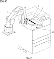
- the device 1 is a device 1 for making a book 9 on demand.
- the input means 28 may or may not be integral with the rest of the device 1. They can be connected by wireless (Wifi) or wired communication means to the rest of the device 1.
- the input means 28 typically comprise a touch pad or a computer. touch screen.
- the device 1 comprises a station 2 for printing and / or receiving a cover arranged to respectively print and / or receive a cover 4.
- Station 2 includes a printer for printing cover 4.
- the station 2 further comprises a feed tray arranged to insert, from the outside of the device 1, a cover 4 printed on the outside of the device 1. This is useful in particular in the case of a thick cardboard cover 4.
- the device 1 comprises a creasing station 21.
- the device 1 comprises a station 3 for printing and / or receiving a corpus arranged to respectively print and / or receive a corpus 5.
- corpus is understood to mean a set of several sheets (preferably of paper) stacked on top of each other to form the pages of the book 9.
- Station 3 includes a printer for printing corpus 5.
- the station 3 further comprises a feed tray designed to insert, from the outside of the device 1, a corpus 5 printed outside the device 1. This is useful in particular in the case of a corpus 5 on a paper. or special material or with special inks (gilding, etc.).
- the cover printing or reception station 2 and the corpus printing or reception station 3 include a printer common to these two stations.
- Stations 2 and 3 typically include a LEXMARK CS923 or equivalent reference printer.
- the device 1 comprises a gating station 22.
- the gasking station 22 comprises a corpus receptacle 23 (arranged to receive and immobilize the corpus 5) and means 24 for girdling a border of the corpus 5 when it is placed in the corpus receptacle 23 of the crimping station 22.
- the device 1 comprises a binding station 6 arranged to assemble the corpus 5 and the cover 4.
- the device 1 comprises a trimming station 25 designed to trim the book 9.
- the device 1 comprises an output station 27 arranged to take the book 9 out from the device 1, for distribution of the book 9 to the user.
- the device 1 comprises routing means 7 arranged and / or programmed to convey, the cover 4 alone, the corpus 5 alone, and the book 9 resulting from the assembly of the cover 4 and the corpus 5, between the different stations 2, 3, 6, 21, 22, 25, 27.
- said device 1 is arranged to deposit glue on a bonding area 8 on the back of the cover inside the binding station 6 before assembly or nesting by gluing the cover 4 on corpus 5 forming a book 9.
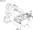
- the routing means comprise (preferably consist of) a COMM control unit described below and a robotic arm provided with fingers 71 (at least two fingers 71 forming a gripper) arranged and / or programmed (in particular by the unit COMM command) to manipulate cover 4 and / or corpus 5.
- This arm of the means 7 is typically a robotic arm with at least six axes of rotation, for example with the reference COMAU Racer 5 or equivalent.
- the routing means 7 are arranged and / or programmed to convey the corpus 5 from the corpus printing or reception station 3 and to the gasking station 22 (possibly via the trimming station 25) in such a way to Greek a side of corpus 5 while the corpus 58 extends vertically or substantially (ie at plus or minus 20 °) vertically in station 22.
- the trimming station 25 is connected to a recovery tank 26, the conveying means 7 being arranged and / or programmed to convey the corpus 5 in an initial format, preferably A4 of the international standard ISO 216 (ICS no 85.080. 10) (ie having a dimension of 210 x 297 mm), up to the trimming station 25, then maintain the corpus 5 in the trimming station 25 (while the corpus 5 extends vertically or substantially (ie to more or minus 20 °) vertically in the station 25) for a cut in a part of the corpus 5 maintained in the conveying means 7 and another part of the corpus 5 cut and directed towards the recovery tank 26, then assemble in the recovery 26 the two parts of the corpus 5 so as to form in the routing means 7 a corpus 5 of reduced format, preferably A5 of the international standard ISO 216 (ICS no 85.080.10) (ie having a dimension of 210 x 148 mm), but of increased thickness compared to its format i initial.
- These means 25 are implemented optionally when the book 9
- the gasking station 22 comprises one or two toothed rollers 24 arranged to girdle (that is to say notch) the corpus 5.
- a jack 37 is arranged to translate each roller 24 along the corpus 5 held in the receptacle. 23.
- a guide rail 38 is arranged to guide each roller in this translational movement.
- Another jack or sidewall clamp 39 is arranged to hold the corpus 5 in position in the receptacle 23 during the crimping.
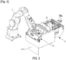
- the binding station 6 comprises a corpus receptacle 20 arranged to receive the corpus 5 in a reception position 16, in which the corpus 5 preferably extends vertically or substantially (i.e. at plus or minus 20 °) vertically.
- the conveying means 7 are arranged and / or programmed to convey the corpus 5 from the crimping station 22 to the binding station 6 (more precisely to the receptacle 20).
- the conveying means 7 are arranged and / or programmed to convey the cover 4 from the printing station 2 to the creasing station 21.
- the conveying means 7 are arranged and / or programmed to insert the cover into the creasing station in a creasing position 11, in which the cover 4 preferably extends vertically or substantially (ie at plus or minus 20 °) vertically.
- the creasing station 21 is designed to pre-fold the cover or crease the cover 4 (before any glue is deposited on the cover 4) along several parallel fold lines extending over an entire width or length of the cover. 4 (preferably on the back of the cover), preferably along two or four parallel fold lines. At least two of these parallel fold lines are in bonding area 8.
- the conveying means 7 are arranged and / or programmed to convey the cover 4 from the creasing station 21 to the binding station 6.
- the binding station 6 comprises heating means 10 arranged to heat and / or keep hot the glue deposited on the gluing zone 8 of the cover 4 before the assembly or gluing of the cover 4 and the cover. corpus 5.
- the conveying means 7 are arranged and / or programmed to position the cover 4 according to the deposition position 12 for which the bonding zone 8 is not located under the heating means 10 and for which the device 1 is arranged to deposit the adhesive on the bonding zone 8. In this position 12 the heating means 10 are inactive.
- the cover 4 rests on a horizontal or substantially horizontal support surface (at plus or minus 20 °) of the binding station 6.
- the binding station 6 comprises locking means 18 arranged to immobilize the cover 4 in the deposit position 12.
- the device 1 comprises a glue gun 72.
- the robotic arm of the means 7 is arranged and / or programmed to grip the glue gun 72 to deposit glue on the bonding zone 8 of the cover 4 while the cover 4 is placed flat in the binding station 6 in its deposit position 12.
- the glue is, for example, PLANATOL Planamelt W glue or equivalent, purchased in the form of granules and extruded in the form of a wire surrounded in the form of the coil 73.
- the device 1, more exactly the arm of the means 7, is arranged and / or programmed to deposit (and possibly determine beforehand) a quantity of glue on the gluing zone 8 of the cover 4 inside the binding station 6 , this quantity of glue being a function of the measured or determined thickness of the corpus 5, typically according to the metadata collected in a PDF file corresponding to the corpus translated by depositing glue.
- the means 10 (more precisely each of the means 201 and 202) are located above the cover 4 for the deposit position 12 of the cover 4.
- the means 10 (more precisely each of the means 201 and 202) are located above the cover 4 for the heating position 13 of the cover 4.
- the means 10 (more precisely each of the means 201 and 202) are located above the bonding zone 8 for the heating position 13 of the cover 4.
- the glue is heated not through the cover 4, but directly above the cover 4 so that the heat coming from the means 10 (more exactly from the means 201) reaches the glue deposited on the cover by the means 7 without first passing through the cover 4. This prevents damaging or burning the cover 4.
- the quantity of heat received by the adhesive is thus maximized in relation to the quantity of heat received by the cover 4.
- the bonding zone 8 is located, among the two faces of the cover 4, on the face of the cover oriented towards the means 10 (more precisely towards each of the means 201 and 202).
- the locking means 18 are arranged to immobilize the cover 4 in the heating position 13.
- the locking means 18 comprise the spout 202 of the heating means 10 which are removably mounted between two positions, including a position for which the cover 4 is not immobilized by the spout 202 and a position for which the cover 4 is immobilized. through the nozzle 202.
- the conveying means 7 are arranged and / or programmed to position the cover 4 according to the pre-assembly position 14 for in which the bonding zone 8 is not located under the heating means 10.
- the heating position 13 is offset from the deposition position 12 in an offset direction 17, preferably horizontal or substantially (i.e. at plus or minus 20 °) horizontal.
- the deposition position 12 is offset from the creasing position 11 at least in the offset direction 17.
- the deposition position 12 is offset from the creasing position 11 along the offset direction 17 and at an angle preferably of 90 ° or substantially equal to 90 ° (i.e. plus or minus 20 °).
- the cover 4 In its creasing position 11, the cover 4 extends perpendicularly or substantially perpendicularly (i.e. at plus or minus 20 °) to the cover 4 in its deposit position 12.
- the pre-assembly position 14 is offset from the heating position 13 along this offset direction 17.
- the cover 4 is located in the same plane called the bonding plane 19 (preferably horizontal or substantially (i.e. at plus or minus 20 °) horizontal) for these positions of deposition 12, heating 13 and pre-assembly 14.
- the binding station 6 is arranged and / or programmed to position the cover 4 according to the assembly position 15.
- the binding station 6 comprises a pivot link 45 (illustrated by the passage between the figures 4 and 6 ) arranged to tilt the support surface of the cover 4 between its positions 14 and 15.
- This pivot link 45 is actuated by a jack 46.
- the assembly position 15 is offset from the pre-assembly position 14 at least partly perpendicular (preferably obliquely) to the offset direction 17 and to the bonding plane 19 of so as to be able to assemble the cover 4 and the corpus 5 by gluing via the gluing zone 8 on which the glue has been deposited.
- the conveying means 7 are arranged and / or programmed so that, in the deposit position 12, the gluing zone 8 is not located under the corpus receptacle 20 of the binding station 6.
- the conveying means 7 are arranged and / or programmed so that, in the pre-assembly position 14, the gluing zone 8 is located under the receptacle 20 of the corpus of the binding station 6.
- the corpus 5 extends perpendicularly or substantially (i.e. at plus or minus 20 °) perpendicular to the cover 4 in its pre-assembly position 14 and in its assembly position 15.
- the conveying means 7 are arranged and / or programmed to exit the book 9 from the binding station 6 perpendicularly or substantially (ie at plus or minus 20 °) perpendicular to the offset direction 17 (and parallel or substantially (ie at more or less 20 °) parallel to the gluing plane 19) and by touching only the corpus 5, that is to say by holding the book by the "gutter".
- the conveying means 7 are arranged and / or programmed to convey the book 9 from the gating station 22 and to the trimming station 25.
- the trimming station 25 is arranged to cut the book 9 along three cutting lines corresponding to three edges of the book 9, the fourth edge of the book 9 corresponding to the bonding edge of the corpus 5 to the cover 4 by the bonding zone 8. Each cutting line is made while the book 9 extends vertically or substantially (ie at plus or minus 20 °) vertically in the station 25.
- the trimming station 25 comprises a blade 51, a stop 54, a motor 52 arranged to actuate the blade 51 against the stop 54 (by means of gears 53) so as to jam the book 9 (or the corpus 5 in cutting case to go from A4 to A5) between the stop 54 and the blade 51 and thus cut an edge of the book 9.
- the device 1 comprises a COMM control unit (not shown), preferably located in the side part 34.
- This control unit comprises at least one computer, a central or computing unit, an analog electronic circuit (preferably dedicated), a digital electronic circuit (preferably dedicated), and / or a microprocessor (preferably dedicated), and / or software means.
- the lower part 31 and the upper part 32 are separated by an opaque separating plate 33 (but provided with passage holes or slits).
- the plate 33 is horizontal or substantially (ie at plus or minus 20 °) horizontal.
- the robotic arm of the means 7 is located at least in part in the upper part 32.
- the binding station 6 is located at least partly in the upper part 32.
- the creasing station 21 is located at least partly in the upper part 32.
- the tightening station 22 is located at least partly in the lower part 31 and is accessible from the upper part 32 by the corpus 5 or the book 9 handled by the arm of the means 7 through a slot made in the plate 33 of seperation.
- the trimming station 25 is located at least partly in the lower part 31 and is accessible from the upper part 32 by the corpus 5 or the book 9 handled by the arm of the means 7 through a slot made in the plate. separation 33.
- the corpus printing or receiving station 3 is located at least partly in the upper part 32 and / or in the lateral part 34.
- the cover printing or receiving station 2 is located at least partly in the upper part 32 and / or in the side part 34.
- the exit station 27 (typically comprising a simple hatch) is located at least in part in the upper part 32.
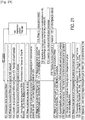
- This embodiment of the method according to the invention comprises steps 99 to 135 described below.
- Steps 101 to 114 follow one another in time by increasing numbers.
- Steps 100 and 115 to 119 follow one another in time by increasing numbers.
- Steps 121 to 135 follow each other in time by increasing numbers.
- steps 121 to 135 is implemented after the block of steps 100 and 115 to 119 and after the block of steps 101 to 114.
- the steps 101 to 135 follow each other in time by increasing numbers.
- this embodiment of the method according to the invention comprises a routing, by the routing means 7, of the cover 4 and / or of the corpus 5 between the different stations 2, 3, 6, 21, 22, 25, 27.
- the conveying means 7 comprise the robotic arm of the means 7 provided with fingers 71 manipulating the cover 4 and / or the corpus 5 to convey it between the different stations 2, 3, 6, 21 , 22, 25, 27.
- These means 7 are also called “robot”, in particular on the figure 21 .
- This embodiment of the method according to the invention for manufacturing a book 9 on demand initially comprises the step 99 of input by the user, on the input means 28, of the book 9 to be printed.
- this embodiment of the method according to the invention comprises the step 100 of printing or receiving, respectively at the station 3 for printing or receiving the corpus, of the corpus 5.
- this embodiment of the method further comprises jogging of the corpus, typically at the output of printer 3.
- each of the steps of the block of steps 100 and 115 to 119 can be implemented before, after, simultaneously or alternately with each of the steps of the block. of steps 101 to 114.
Landscapes
- Engineering & Computer Science (AREA)
- Mechanical Engineering (AREA)
- Manufacturing & Machinery (AREA)
- Life Sciences & Earth Sciences (AREA)
- Forests & Forestry (AREA)
- Robotics (AREA)
- Folding Of Thin Sheet-Like Materials, Special Discharging Devices, And Others (AREA)
- Making Paper Articles (AREA)
- Feeding Of Articles By Means Other Than Belts Or Rollers (AREA)
- Collation Of Sheets And Webs (AREA)
Priority Applications (1)
| Application Number | Priority Date | Filing Date | Title |
|---|---|---|---|
| EP24178787.8A EP4400275B1 (de) | 2019-03-06 | 2020-02-07 | Vorrichtung zum robotischen drucken von einheitenerzeugten büchern und verfahren dafür |
Applications Claiming Priority (3)
| Application Number | Priority Date | Filing Date | Title |
|---|---|---|---|
| FR1902286A FR3093467B1 (fr) | 2019-03-06 | 2019-03-06 | Dispositif d’impression robotisée de livres produits à l'unité et procédé associé. |
| PCT/EP2020/053184 WO2020177978A1 (fr) | 2019-03-06 | 2020-02-07 | Dispositif d'impression robotisee de livres produits a l'unite et procede associe |
| EP20705019.6A EP3727869B1 (de) | 2019-03-06 | 2020-02-07 | Vorrichtung zum robotischen drucken von einzeln gedruckten büchern und zugehöriges verfahren |
Related Parent Applications (2)
| Application Number | Title | Priority Date | Filing Date |
|---|---|---|---|
| EP20705019.6A Division EP3727869B1 (de) | 2019-03-06 | 2020-02-07 | Vorrichtung zum robotischen drucken von einzeln gedruckten büchern und zugehöriges verfahren |
| EP20705019.6A Division-Into EP3727869B1 (de) | 2019-03-06 | 2020-02-07 | Vorrichtung zum robotischen drucken von einzeln gedruckten büchern und zugehöriges verfahren |
Related Child Applications (1)
| Application Number | Title | Priority Date | Filing Date |
|---|---|---|---|
| EP24178787.8A Division EP4400275B1 (de) | 2019-03-06 | 2020-02-07 | Vorrichtung zum robotischen drucken von einheitenerzeugten büchern und verfahren dafür |
Publications (3)
| Publication Number | Publication Date |
|---|---|
| EP3795366A1 true EP3795366A1 (de) | 2021-03-24 |
| EP3795366B1 EP3795366B1 (de) | 2024-06-12 |
| EP3795366C0 EP3795366C0 (de) | 2024-06-12 |
Family
ID=67262623
Family Applications (3)
| Application Number | Title | Priority Date | Filing Date |
|---|---|---|---|
| EP20205537.2A Active EP3795366B1 (de) | 2019-03-06 | 2020-02-07 | Vorrichtung zum robotergestützten drucken von einzeln hergestellten büchern, und entsprechendes verfahren |
| EP24178787.8A Active EP4400275B1 (de) | 2019-03-06 | 2020-02-07 | Vorrichtung zum robotischen drucken von einheitenerzeugten büchern und verfahren dafür |
| EP20705019.6A Active EP3727869B1 (de) | 2019-03-06 | 2020-02-07 | Vorrichtung zum robotischen drucken von einzeln gedruckten büchern und zugehöriges verfahren |
Family Applications After (2)
| Application Number | Title | Priority Date | Filing Date |
|---|---|---|---|
| EP24178787.8A Active EP4400275B1 (de) | 2019-03-06 | 2020-02-07 | Vorrichtung zum robotischen drucken von einheitenerzeugten büchern und verfahren dafür |
| EP20705019.6A Active EP3727869B1 (de) | 2019-03-06 | 2020-02-07 | Vorrichtung zum robotischen drucken von einzeln gedruckten büchern und zugehöriges verfahren |
Country Status (4)
| Country | Link |
|---|---|
| US (3) | US11878543B2 (de) |
| EP (3) | EP3795366B1 (de) |
| FR (1) | FR3093469B1 (de) |
| WO (1) | WO2020177978A1 (de) |
Families Citing this family (1)
| Publication number | Priority date | Publication date | Assignee | Title |
|---|---|---|---|---|
| DE102020115827A1 (de) | 2020-06-16 | 2021-12-16 | Baumann Maschinenbau Solms Gmbh & Co.Kg | Verfahren zum Ver- und/oder Bearbeiten eines Stapels blattförmigen Guts sowie Schneidanlage |
Citations (6)
| Publication number | Priority date | Publication date | Assignee | Title |
|---|---|---|---|---|
| WO1999038707A1 (en) | 1998-01-30 | 1999-08-05 | Marsh Jeffrey D | Apparatus for and method of binding a book |
| WO2001056794A1 (en) | 2000-02-02 | 2001-08-09 | Aprion Digital Ltd. | A paperback finishing machine |
| EP1196296A1 (de) | 1999-04-29 | 2002-04-17 | Jeffrey D. Marsh | Vorrichtung und verfahren zum binden und schneiden von büchern |
| WO2011108935A1 (en) * | 2010-03-05 | 2011-09-09 | Book Factory Systems B.V. | Small batch book production |
| JP5070482B1 (ja) * | 2012-01-19 | 2012-11-14 | 芳野マシナリー株式会社 | 製本装置 |
| DE102016218043A1 (de) * | 2016-09-20 | 2018-03-22 | Bundesdruckerei Gmbh | Vorrichtung und ein Verfahren zum Vereinzeln und Sortieren von Doppelseiten für ein buchförmiges Ausweis-, Wert- oder Sicherheitsdokuments, Verfahren und System zur Herstellung eines buchförmiges Ausweis-, Wert- oder Sicherheitsdokuments |
Family Cites Families (7)
| Publication number | Priority date | Publication date | Assignee | Title |
|---|---|---|---|---|
| US3160315A (en) * | 1961-03-30 | 1964-12-08 | Publisher S Vending Services I | Book vending machine |
| US5531429A (en) * | 1995-03-29 | 1996-07-02 | National Computer Systems, Inc. | Variable printing and selective binding of booklets |
| WO2016051528A1 (ja) * | 2014-09-30 | 2016-04-07 | ブラザー工業株式会社 | 製本装置、用紙搬送装置、及び裁断装置 |
| DE102015202995A1 (de) | 2015-02-19 | 2016-08-25 | Bundesdruckerei Gmbh | Anlage und Verfahren zum Produzieren von buchförmig ausgestalteten Identifikationsdokumenten sowie Verfahren zum Errichten der Produktionsanlage |
| CN105817392B (zh) * | 2016-05-03 | 2018-04-13 | 珠海格力电器股份有限公司 | 自动涂胶装置 |
| DE102016218042B4 (de) | 2016-09-20 | 2019-09-12 | Bundesdruckerei Gmbh | Halte- und Transportvorrichtung, Verfahren zum Betrieb einer Halte- und Transportvorrichtung, System und Verfahren zur Herstellung eines buchförmigen Ausweis-, Wert- oder Sicherheitsdokuments |
| CN108704792A (zh) * | 2018-07-18 | 2018-10-26 | 芜湖固高自动化技术有限公司 | 一种用于机器人末端的喷涂装置 |
-
2020
- 2020-02-07 WO PCT/EP2020/053184 patent/WO2020177978A1/fr not_active Ceased
- 2020-02-07 EP EP20205537.2A patent/EP3795366B1/de active Active
- 2020-02-07 US US17/310,974 patent/US11878543B2/en active Active
- 2020-02-07 EP EP24178787.8A patent/EP4400275B1/de active Active
- 2020-02-07 EP EP20705019.6A patent/EP3727869B1/de active Active
- 2020-02-07 FR FR2001248A patent/FR3093469B1/fr active Active
-
2023
- 2023-11-27 US US18/520,010 patent/US12214610B2/en active Active
-
2025
- 2025-01-29 US US19/040,172 patent/US12605958B2/en active Active
Patent Citations (6)
| Publication number | Priority date | Publication date | Assignee | Title |
|---|---|---|---|---|
| WO1999038707A1 (en) | 1998-01-30 | 1999-08-05 | Marsh Jeffrey D | Apparatus for and method of binding a book |
| EP1196296A1 (de) | 1999-04-29 | 2002-04-17 | Jeffrey D. Marsh | Vorrichtung und verfahren zum binden und schneiden von büchern |
| WO2001056794A1 (en) | 2000-02-02 | 2001-08-09 | Aprion Digital Ltd. | A paperback finishing machine |
| WO2011108935A1 (en) * | 2010-03-05 | 2011-09-09 | Book Factory Systems B.V. | Small batch book production |
| JP5070482B1 (ja) * | 2012-01-19 | 2012-11-14 | 芳野マシナリー株式会社 | 製本装置 |
| DE102016218043A1 (de) * | 2016-09-20 | 2018-03-22 | Bundesdruckerei Gmbh | Vorrichtung und ein Verfahren zum Vereinzeln und Sortieren von Doppelseiten für ein buchförmiges Ausweis-, Wert- oder Sicherheitsdokuments, Verfahren und System zur Herstellung eines buchförmiges Ausweis-, Wert- oder Sicherheitsdokuments |
Also Published As
| Publication number | Publication date |
|---|---|
| FR3093469B1 (fr) | 2021-06-04 |
| US12214610B2 (en) | 2025-02-04 |
| EP3727869A1 (de) | 2020-10-28 |
| EP3795366B1 (de) | 2024-06-12 |
| US12605958B2 (en) | 2026-04-21 |
| FR3093469A1 (fr) | 2020-09-11 |
| EP3795366C0 (de) | 2024-06-12 |
| US20240092111A1 (en) | 2024-03-21 |
| EP4400275A2 (de) | 2024-07-17 |
| EP4400275A3 (de) | 2024-10-09 |
| WO2020177978A1 (fr) | 2020-09-10 |
| US20220134791A1 (en) | 2022-05-05 |
| US20250170849A1 (en) | 2025-05-29 |
| EP3727869B1 (de) | 2021-03-17 |
| EP4400275C0 (de) | 2025-11-26 |
| EP4400275B1 (de) | 2025-11-26 |
| US11878543B2 (en) | 2024-01-23 |
Similar Documents
| Publication | Publication Date | Title |
|---|---|---|
| WO2009112707A1 (fr) | Procede et dispositif pour la realisation de boites a partir d'un ensemble de decoupes | |
| FR2986511A1 (fr) | Procede et dispositif de formation d'une boite en carton ondule autour d'un mandrin avec arete de reference | |
| EP3727869B1 (de) | Vorrichtung zum robotischen drucken von einzeln gedruckten büchern und zugehöriges verfahren | |
| FR3093468A1 (fr) | Dispositif d’impression robotisée de livres produits à l'unité et procédé associé. | |
| FR3011767A1 (fr) | Machine universelle de fabrication de panneaux informatifs | |
| EP0681975B1 (de) | Vorrichtung zum Bremsen von plattenförmigen Elementen in einer Auslegerstation einer Maschine zur Behandlung von solchen Elementen | |
| EP1886831B1 (de) | Vorrichtung zur Herstellung eines Albums | |
| CA2695392C (fr) | Systeme de depose de documents dans des caisses | |
| BE889349A (fr) | Procede et appareil d'assemblage de matiere en feuille, notamment pour alimenter en continu des imprimantes rapides | |
| EP2154001B1 (de) | Anlage zur automatischen Herstellung eines gebundenen Albums aus Einzelblättern und insbesondere eines Fotoalbums | |
| EP1379453B1 (de) | Verfahren und vorrichtung zur bearbeitung und positionierung von trennelementen zwischen stapelbaren flachelementen und anwendung | |
| EP0030204B1 (de) | Kartei für verschiedene Belege | |
| CA2648827A1 (fr) | Dispositif de taquage automatique d'articles de courrier | |
| EP3566879A1 (de) | Automatisiertes verfahren der digitalen herstellung von werkstücken | |
| FR2752564A1 (fr) | Pochette d'emballage pour travaux photographiques | |
| WO2018091827A1 (fr) | Dispositif et procédé pour appliquer manuellement une étiquette sur un objet prédéterminé | |
| FR2783190A1 (fr) | Dispositif pour la destruction et la recuperation selective d'imprimes relies tels que des livres | |
| EP0523305A1 (de) | Vorrichtung mit Planetrollen zum Behandeln von Wertpapieren wie Banknoten | |
| FR2510034A1 (fr) | Machine pour la fabrication automatique de boites | |
| FR2904580A1 (fr) | Dispositif pour encoller de maniere automatique des feuilles de papier ou de carton | |
| FR2717715A1 (fr) | Machine de mise sous pli intégrant la reconnaissance de caractères par lecture directe pour effectuer le regroupement des documents. | |
| FR2831151A1 (fr) | Procede et module de pliage | |
| FR2748011A1 (fr) | Module d'interface destine a etre agence en aval d'une machine imprimante | |
| FR2764276A1 (fr) | Procede et installation pour la preparation automatique de commandes d'affiches publicitaires | |
| FR2485892A1 (fr) | Procede et dispositif de division d'une feuille ou d'une demi-feuille de tabac en parties utilisables par exemple en sous-capes ou en capes |
Legal Events
| Date | Code | Title | Description |
|---|---|---|---|
| PUAI | Public reference made under article 153(3) epc to a published international application that has entered the european phase |
Free format text: ORIGINAL CODE: 0009012 |
|
| STAA | Information on the status of an ep patent application or granted ep patent |
Free format text: STATUS: THE APPLICATION HAS BEEN PUBLISHED |
|
| AC | Divisional application: reference to earlier application |
Ref document number: 3727869 Country of ref document: EP Kind code of ref document: P |
|
| AK | Designated contracting states |
Kind code of ref document: A1 Designated state(s): AL AT BE BG CH CY CZ DE DK EE ES FI FR GB GR HR HU IE IS IT LI LT LU LV MC MK MT NL NO PL PT RO RS SE SI SK SM TR |
|
| STAA | Information on the status of an ep patent application or granted ep patent |
Free format text: STATUS: REQUEST FOR EXAMINATION WAS MADE |
|
| 17P | Request for examination filed |
Effective date: 20210924 |
|
| RBV | Designated contracting states (corrected) |
Designated state(s): AL AT BE BG CH CY CZ DE DK EE ES FI FR GB GR HR HU IE IS IT LI LT LU LV MC MK MT NL NO PL PT RO RS SE SI SK SM TR |
|
| STAA | Information on the status of an ep patent application or granted ep patent |
Free format text: STATUS: EXAMINATION IS IN PROGRESS |
|
| 17Q | First examination report despatched |
Effective date: 20220221 |
|
| GRAP | Despatch of communication of intention to grant a patent |
Free format text: ORIGINAL CODE: EPIDOSNIGR1 |
|
| STAA | Information on the status of an ep patent application or granted ep patent |
Free format text: STATUS: GRANT OF PATENT IS INTENDED |
|
| INTG | Intention to grant announced |
Effective date: 20230213 |
|
| 19U | Interruption of proceedings before grant |
Effective date: 20221205 |
|
| 19W | Proceedings resumed before grant after interruption of proceedings |
Effective date: 20240102 |
|
| RAP3 | Party data changed (applicant data changed or rights of an application transferred) |
Owner name: R&D AUTOMATION |
|
| GRAS | Grant fee paid |
Free format text: ORIGINAL CODE: EPIDOSNIGR3 |
|
| GRAA | (expected) grant |
Free format text: ORIGINAL CODE: 0009210 |
|
| STAA | Information on the status of an ep patent application or granted ep patent |
Free format text: STATUS: THE PATENT HAS BEEN GRANTED |
|
| AC | Divisional application: reference to earlier application |
Ref document number: 3727869 Country of ref document: EP Kind code of ref document: P |
|
| AK | Designated contracting states |
Kind code of ref document: B1 Designated state(s): AL AT BE BG CH CY CZ DE DK EE ES FI FR GB GR HR HU IE IS IT LI LT LU LV MC MK MT NL NO PL PT RO RS SE SI SK SM TR |
|
| REG | Reference to a national code |
Ref country code: GB Ref legal event code: FG4D Free format text: NOT ENGLISH |
|
| REG | Reference to a national code |
Ref country code: CH Ref legal event code: EP |
|
| REG | Reference to a national code |
Ref country code: IE Ref legal event code: FG4D Free format text: LANGUAGE OF EP DOCUMENT: FRENCH |
|
| REG | Reference to a national code |
Ref country code: DE Ref legal event code: R096 Ref document number: 602020032228 Country of ref document: DE |
|
| U01 | Request for unitary effect filed |
Effective date: 20240709 |
|
| U07 | Unitary effect registered |
Designated state(s): AT BE BG DE DK EE FI FR IT LT LU LV MT NL PT SE SI Effective date: 20240716 |
|
| PG25 | Lapsed in a contracting state [announced via postgrant information from national office to epo] |
Ref country code: HR Free format text: LAPSE BECAUSE OF FAILURE TO SUBMIT A TRANSLATION OF THE DESCRIPTION OR TO PAY THE FEE WITHIN THE PRESCRIBED TIME-LIMIT Effective date: 20240612 |
|
| PG25 | Lapsed in a contracting state [announced via postgrant information from national office to epo] |
Ref country code: GR Free format text: LAPSE BECAUSE OF FAILURE TO SUBMIT A TRANSLATION OF THE DESCRIPTION OR TO PAY THE FEE WITHIN THE PRESCRIBED TIME-LIMIT Effective date: 20240913 |
|
| PG25 | Lapsed in a contracting state [announced via postgrant information from national office to epo] |
Ref country code: ES Free format text: LAPSE BECAUSE OF FAILURE TO SUBMIT A TRANSLATION OF THE DESCRIPTION OR TO PAY THE FEE WITHIN THE PRESCRIBED TIME-LIMIT Effective date: 20240612 |
|
| PG25 | Lapsed in a contracting state [announced via postgrant information from national office to epo] |
Ref country code: NO Free format text: LAPSE BECAUSE OF FAILURE TO SUBMIT A TRANSLATION OF THE DESCRIPTION OR TO PAY THE FEE WITHIN THE PRESCRIBED TIME-LIMIT Effective date: 20240912 Ref country code: HR Free format text: LAPSE BECAUSE OF FAILURE TO SUBMIT A TRANSLATION OF THE DESCRIPTION OR TO PAY THE FEE WITHIN THE PRESCRIBED TIME-LIMIT Effective date: 20240612 Ref country code: GR Free format text: LAPSE BECAUSE OF FAILURE TO SUBMIT A TRANSLATION OF THE DESCRIPTION OR TO PAY THE FEE WITHIN THE PRESCRIBED TIME-LIMIT Effective date: 20240913 Ref country code: ES Free format text: LAPSE BECAUSE OF FAILURE TO SUBMIT A TRANSLATION OF THE DESCRIPTION OR TO PAY THE FEE WITHIN THE PRESCRIBED TIME-LIMIT Effective date: 20240612 Ref country code: RS Free format text: LAPSE BECAUSE OF FAILURE TO SUBMIT A TRANSLATION OF THE DESCRIPTION OR TO PAY THE FEE WITHIN THE PRESCRIBED TIME-LIMIT Effective date: 20240912 |
|
| PG25 | Lapsed in a contracting state [announced via postgrant information from national office to epo] |
Ref country code: PL Free format text: LAPSE BECAUSE OF FAILURE TO SUBMIT A TRANSLATION OF THE DESCRIPTION OR TO PAY THE FEE WITHIN THE PRESCRIBED TIME-LIMIT Effective date: 20240612 |
|
| PG25 | Lapsed in a contracting state [announced via postgrant information from national office to epo] |
Ref country code: IS Free format text: LAPSE BECAUSE OF FAILURE TO SUBMIT A TRANSLATION OF THE DESCRIPTION OR TO PAY THE FEE WITHIN THE PRESCRIBED TIME-LIMIT Effective date: 20241012 |
|
| PG25 | Lapsed in a contracting state [announced via postgrant information from national office to epo] |
Ref country code: CZ Free format text: LAPSE BECAUSE OF FAILURE TO SUBMIT A TRANSLATION OF THE DESCRIPTION OR TO PAY THE FEE WITHIN THE PRESCRIBED TIME-LIMIT Effective date: 20240612 |
|
| PG25 | Lapsed in a contracting state [announced via postgrant information from national office to epo] |
Ref country code: SK Free format text: LAPSE BECAUSE OF FAILURE TO SUBMIT A TRANSLATION OF THE DESCRIPTION OR TO PAY THE FEE WITHIN THE PRESCRIBED TIME-LIMIT Effective date: 20240612 Ref country code: RO Free format text: LAPSE BECAUSE OF FAILURE TO SUBMIT A TRANSLATION OF THE DESCRIPTION OR TO PAY THE FEE WITHIN THE PRESCRIBED TIME-LIMIT Effective date: 20240612 |
|
| PG25 | Lapsed in a contracting state [announced via postgrant information from national office to epo] |
Ref country code: SM Free format text: LAPSE BECAUSE OF FAILURE TO SUBMIT A TRANSLATION OF THE DESCRIPTION OR TO PAY THE FEE WITHIN THE PRESCRIBED TIME-LIMIT Effective date: 20240612 |
|
| PG25 | Lapsed in a contracting state [announced via postgrant information from national office to epo] |
Ref country code: SM Free format text: LAPSE BECAUSE OF FAILURE TO SUBMIT A TRANSLATION OF THE DESCRIPTION OR TO PAY THE FEE WITHIN THE PRESCRIBED TIME-LIMIT Effective date: 20240612 Ref country code: SK Free format text: LAPSE BECAUSE OF FAILURE TO SUBMIT A TRANSLATION OF THE DESCRIPTION OR TO PAY THE FEE WITHIN THE PRESCRIBED TIME-LIMIT Effective date: 20240612 Ref country code: RO Free format text: LAPSE BECAUSE OF FAILURE TO SUBMIT A TRANSLATION OF THE DESCRIPTION OR TO PAY THE FEE WITHIN THE PRESCRIBED TIME-LIMIT Effective date: 20240612 Ref country code: PL Free format text: LAPSE BECAUSE OF FAILURE TO SUBMIT A TRANSLATION OF THE DESCRIPTION OR TO PAY THE FEE WITHIN THE PRESCRIBED TIME-LIMIT Effective date: 20240612 Ref country code: IS Free format text: LAPSE BECAUSE OF FAILURE TO SUBMIT A TRANSLATION OF THE DESCRIPTION OR TO PAY THE FEE WITHIN THE PRESCRIBED TIME-LIMIT Effective date: 20241012 Ref country code: CZ Free format text: LAPSE BECAUSE OF FAILURE TO SUBMIT A TRANSLATION OF THE DESCRIPTION OR TO PAY THE FEE WITHIN THE PRESCRIBED TIME-LIMIT Effective date: 20240612 |
|
| U20 | Renewal fee for the european patent with unitary effect paid |
Year of fee payment: 6 Effective date: 20250227 |
|
| PLBE | No opposition filed within time limit |
Free format text: ORIGINAL CODE: 0009261 |
|
| STAA | Information on the status of an ep patent application or granted ep patent |
Free format text: STATUS: NO OPPOSITION FILED WITHIN TIME LIMIT |
|
| 26N | No opposition filed |
Effective date: 20250313 |
|
| PG25 | Lapsed in a contracting state [announced via postgrant information from national office to epo] |
Ref country code: MC Free format text: LAPSE BECAUSE OF FAILURE TO SUBMIT A TRANSLATION OF THE DESCRIPTION OR TO PAY THE FEE WITHIN THE PRESCRIBED TIME-LIMIT Effective date: 20240612 |
|
| REG | Reference to a national code |
Ref country code: CH Ref legal event code: PL |
|
| PG25 | Lapsed in a contracting state [announced via postgrant information from national office to epo] |
Ref country code: CH Free format text: LAPSE BECAUSE OF NON-PAYMENT OF DUE FEES Effective date: 20250228 |
|
| GBPC | Gb: european patent ceased through non-payment of renewal fee |
Effective date: 20250207 |
|
| PG25 | Lapsed in a contracting state [announced via postgrant information from national office to epo] |
Ref country code: GB Free format text: LAPSE BECAUSE OF NON-PAYMENT OF DUE FEES Effective date: 20250207 |
|
| PG25 | Lapsed in a contracting state [announced via postgrant information from national office to epo] |
Ref country code: IE Free format text: LAPSE BECAUSE OF NON-PAYMENT OF DUE FEES Effective date: 20250207 |
|
| U20 | Renewal fee for the european patent with unitary effect paid |
Year of fee payment: 7 Effective date: 20260225 |