EP3796479B1 - Niederspannungsverbinder - Google Patents
Niederspannungsverbinder Download PDFInfo
- Publication number
- EP3796479B1 EP3796479B1 EP20195226.4A EP20195226A EP3796479B1 EP 3796479 B1 EP3796479 B1 EP 3796479B1 EP 20195226 A EP20195226 A EP 20195226A EP 3796479 B1 EP3796479 B1 EP 3796479B1
- Authority
- EP
- European Patent Office
- Prior art keywords
- connector
- main body
- connector main
- head
- clipping
- Prior art date
- Legal status (The legal status is an assumption and is not a legal conclusion. Google has not performed a legal analysis and makes no representation as to the accuracy of the status listed.)
- Active
Links
Images


Classifications
-
- H—ELECTRICITY
- H01—ELECTRIC ELEMENTS
- H01R—ELECTRICALLY-CONDUCTIVE CONNECTIONS; STRUCTURAL ASSOCIATIONS OF A PLURALITY OF MUTUALLY-INSULATED ELECTRICAL CONNECTING ELEMENTS; COUPLING DEVICES; CURRENT COLLECTORS
- H01R13/00—Details of coupling devices of the kinds covered by groups H01R12/70 or H01R24/00 - H01R33/00
- H01R13/62—Means for facilitating engagement or disengagement of coupling parts or for holding them in engagement
- H01R13/627—Snap or like fastening
- H01R13/6271—Latching means integral with the housing
- H01R13/6273—Latching means integral with the housing comprising two latching arms
-
- H—ELECTRICITY
- H01—ELECTRIC ELEMENTS
- H01R—ELECTRICALLY-CONDUCTIVE CONNECTIONS; STRUCTURAL ASSOCIATIONS OF A PLURALITY OF MUTUALLY-INSULATED ELECTRICAL CONNECTING ELEMENTS; COUPLING DEVICES; CURRENT COLLECTORS
- H01R13/00—Details of coupling devices of the kinds covered by groups H01R12/70 or H01R24/00 - H01R33/00
- H01R13/73—Means for mounting coupling parts to apparatus or structures, e.g. to a wall
- H01R13/74—Means for mounting coupling parts in openings of a panel
- H01R13/748—Means for mounting coupling parts in openings of a panel using one or more screws
-
- H—ELECTRICITY
- H01—ELECTRIC ELEMENTS
- H01R—ELECTRICALLY-CONDUCTIVE CONNECTIONS; STRUCTURAL ASSOCIATIONS OF A PLURALITY OF MUTUALLY-INSULATED ELECTRICAL CONNECTING ELEMENTS; COUPLING DEVICES; CURRENT COLLECTORS
- H01R13/00—Details of coupling devices of the kinds covered by groups H01R12/70 or H01R24/00 - H01R33/00
- H01R13/40—Securing contact members in or to a base or case; Insulating of contact members
- H01R13/42—Securing in a demountable manner
- H01R13/436—Securing a plurality of contact members by one locking piece or operation
- H01R13/4367—Insertion of locking piece from the rear
-
- H—ELECTRICITY
- H01—ELECTRIC ELEMENTS
- H01R—ELECTRICALLY-CONDUCTIVE CONNECTIONS; STRUCTURAL ASSOCIATIONS OF A PLURALITY OF MUTUALLY-INSULATED ELECTRICAL CONNECTING ELEMENTS; COUPLING DEVICES; CURRENT COLLECTORS
- H01R13/00—Details of coupling devices of the kinds covered by groups H01R12/70 or H01R24/00 - H01R33/00
- H01R13/46—Bases; Cases
- H01R13/502—Bases; Cases composed of different pieces
- H01R13/506—Bases; Cases composed of different pieces assembled by snap action of the parts
-
- H—ELECTRICITY
- H01—ELECTRIC ELEMENTS
- H01R—ELECTRICALLY-CONDUCTIVE CONNECTIONS; STRUCTURAL ASSOCIATIONS OF A PLURALITY OF MUTUALLY-INSULATED ELECTRICAL CONNECTING ELEMENTS; COUPLING DEVICES; CURRENT COLLECTORS
- H01R13/00—Details of coupling devices of the kinds covered by groups H01R12/70 or H01R24/00 - H01R33/00
- H01R13/46—Bases; Cases
- H01R13/52—Dustproof, splashproof, drip-proof, waterproof, or flameproof cases
- H01R13/5202—Sealing means between parts of housing or between housing part and a wall, e.g. sealing rings
-
- H—ELECTRICITY
- H01—ELECTRIC ELEMENTS
- H01R—ELECTRICALLY-CONDUCTIVE CONNECTIONS; STRUCTURAL ASSOCIATIONS OF A PLURALITY OF MUTUALLY-INSULATED ELECTRICAL CONNECTING ELEMENTS; COUPLING DEVICES; CURRENT COLLECTORS
- H01R13/00—Details of coupling devices of the kinds covered by groups H01R12/70 or H01R24/00 - H01R33/00
- H01R13/62—Means for facilitating engagement or disengagement of coupling parts or for holding them in engagement
- H01R13/629—Additional means for facilitating engagement or disengagement of coupling parts, e.g. aligning or guiding means, levers, gas pressure electrical locking indicators, manufacturing tolerances
- H01R13/631—Additional means for facilitating engagement or disengagement of coupling parts, e.g. aligning or guiding means, levers, gas pressure electrical locking indicators, manufacturing tolerances for engagement only
-
- H—ELECTRICITY
- H01—ELECTRIC ELEMENTS
- H01R—ELECTRICALLY-CONDUCTIVE CONNECTIONS; STRUCTURAL ASSOCIATIONS OF A PLURALITY OF MUTUALLY-INSULATED ELECTRICAL CONNECTING ELEMENTS; COUPLING DEVICES; CURRENT COLLECTORS
- H01R13/00—Details of coupling devices of the kinds covered by groups H01R12/70 or H01R24/00 - H01R33/00
- H01R13/64—Means for preventing incorrect coupling
-
- H—ELECTRICITY
- H01—ELECTRIC ELEMENTS
- H01R—ELECTRICALLY-CONDUCTIVE CONNECTIONS; STRUCTURAL ASSOCIATIONS OF A PLURALITY OF MUTUALLY-INSULATED ELECTRICAL CONNECTING ELEMENTS; COUPLING DEVICES; CURRENT COLLECTORS
- H01R2107/00—Four or more poles
-
- H—ELECTRICITY
- H01—ELECTRIC ELEMENTS
- H01R—ELECTRICALLY-CONDUCTIVE CONNECTIONS; STRUCTURAL ASSOCIATIONS OF A PLURALITY OF MUTUALLY-INSULATED ELECTRICAL CONNECTING ELEMENTS; COUPLING DEVICES; CURRENT COLLECTORS
- H01R24/00—Two-part coupling devices, or either of their cooperating parts, characterised by their overall structure
- H01R24/20—Coupling parts carrying sockets, clips or analogous contacts and secured only to wire or cable
-
- H—ELECTRICITY
- H01—ELECTRIC ELEMENTS
- H01R—ELECTRICALLY-CONDUCTIVE CONNECTIONS; STRUCTURAL ASSOCIATIONS OF A PLURALITY OF MUTUALLY-INSULATED ELECTRICAL CONNECTING ELEMENTS; COUPLING DEVICES; CURRENT COLLECTORS
- H01R31/00—Coupling parts supported only by co-operation with counterpart
- H01R31/06—Intermediate parts for linking two coupling parts, e.g. adapter
Definitions
- the present disclosure relates to an electric-circuit connector, and particularly relates to a low-voltage connector.
- Low-voltage connectors are frequently utilized in vehicles; for example, the signal line for connecting an electric-motor controller to a vehicle computer is required to use a low-voltage connector. Because of the vibration generated during the travelling of vehicles, the connector heads tend to separate at the position of low-voltage connectors, resulting in that the signal line would be disconnected, and thus the vehicle computer would lose control on the electric motor, which would cause a serious potential safety hazard.
- a plug-and-socket connector assembly includes an electrical plug connector which includes two retaining tongues each having an actuating free end and a retaining region, and an electrical socket connector which includes two lugs each having a locking hole.
- the electrical socket connector When the electrical socket connector is brought into mating engagement with the electrical plug connector, the retaining region is snap-fitted in the locking hole of a corresponding one of the lugs.
- the actuating free ends of the retaining tongues can be manually pressed toward each other against the biasing forces of the retaining tongues to disengage the retaining regions of the retaining tongues from the locking holes of the lugs so as to permit removal of the electrical plug connector.
- Document JP2008166046A discloses two pieces each of backlash tightening ribs with a cross-sectional crest shape are formed on each face on the outer circumference of tube part of a front wall member which constitutes a terminal housing part in a female housing.
- An engaging groove of trapezoidal cross-section in which the backlash tightening rib is engaged is formed on the inner circumference face of the small hood portion of a male housing.
- the width A of an opening edge of the engaging groove is established to be smaller than the width B of a skirt portion of the backlash tightening rib. Since the both skirt portions of the backlash tightening rib and the corresponding opening edges of the engaging groove are mutually crushed, backlash tightening is carried out. Vibration is prevented at the positions close to the position where male and female terminal fittings are engaged and connected. Thereby, backlash tightening rib and the engaging groove can be established throughout the whole circumference and backlash can be tightened uniformly from the whole circumference.
- a junction terminal is accommodated in a connector housing to connect a pin terminal fitted on a case of an electric instrument with a receptacle terminal of a wiring harness connector.
- the junction terminal includes a female electrical contact portion to electrically connect with the pin terminal of the electric instrument, a male electrical contact portion to electrically connect with the receptacle terminal of the wiring harness connector, and a bridging portion to connect the female electrical contact portion with the male electrical contact portion.
- the male electrical contact portion is constructed so as to be correctly positioned by a positioning member attached to the connector housing.
- the male electrical contact portion is arranged such that a first longitudinal line passing an intermediate point of the male electrical contact portion aligns with a second longitudinal line passing an intermediate point of the female electrical contact portion.
- each connector has a grommet retainer that retains a grommet at the rear of the connector, and wherein when the connectors are mated they securely hold a first connector within a mounting wall.
- Each connector has a retainer lying rearward of a grommet and having a plurality of retainer holes that pass wires that extend through the grommet, the retainer having walls which engage the grommet to retain it and assure proper orientation of the retainer so the holes of the retainer and grommet are aligned.
- a first connector which can be inserted into a hole of a mounting wall, has resilient tines that press against the hole surface and that have latch parts at their front ends that form shoulders that engage a face of the wall.
- the second connector has a plurality of wedges that each move immediately inward of a corresponding tine as the connectors move together for mating, to prevent the tines from being radially inwardly deflected, to thereby lock the first connector to the mounting wall.
- Document JPS49102290U discloses a latch arm having a male housing portion and a female housing portion capable of being fitted, one end of the male housing portion being fixed at one end to provide elastic force and having a locking projection,
- An electrical connector housing characterized in that a female housing part is formed with an engaging part which can be held to the latching projection of the latch arm.
- the vacuum connector of the present invention includes a vacuum connector body connected to a line installed to control various equipment installed in a vacuum chamber after vacuuming a predetermined space in an industrial facility for manufacturing an article in a vacuum state.
- the vacuum connector body has a flange having a diameter larger than the diameter of one end at an outer diameter of the other end, and one side of the flange is inclined so that the width of the cross section decreases from the shaft center side toward the outer circumferential surface thereof. It is characterized in that the inclined surface is formed.
- a connector comprises: a housing in which a communication slot is formed in a partition wall connecting between adjacent terminal accommodating chambers; and a connection terminal having a terminal body portion connected to a wire connection portion.
- the terminal body portion includes: a first side wall on which a male connection portion is formed, a second side wall having a slit; and an elastic portion contacting portions disposed in the terminal body portion and contacting the male connection portion inserted in the slit.
- the connection slot is disposed at a position offset from the center in the vertical direction of the terminal accommodation chamber.
- the male connection terminal and the slot are arranged at a position offset from the center in the vertical direction of the terminal body portion so as to coincide with the connection slot.
- Document JPH10241790A discloses a trapezoidal guide rib as a projecting part in the upper and lower middle part of the sidewall of a male connector housing along the insertion direction.
- a guide groove as a recessed part is provided in the vertically intermediate part of a side wall opposite the fitting hood part of a female connector housing.
- the section of the trapezoidal guide rib is formed to be trapezoidal, so as to be expanded to a tip side, and a slope symmetrical with respect to upper and lower sides is formed.
- the section of the guide groove is expanded to the deep side of the sidewall and formed to be trapezoidal corresponding to the section of the guide rib, and a slope which is symmetrical in upper and lower sides is formed.
- the present disclosure provides a low-voltage connector, which, by providing snap-fitting structures having different functions, realizes a good anti-vibration capacity and a reliable connection structure.
- the second connector head is provided with one slot on an inner wall on one side in a length direction
- the connector main body is correspondingly provided with one projection on an outer wall in a length direction
- the projection and the slot form a fool proofing structure, and after the projection and the slot are matched the connector main body is capable of being plug-connected to the second connector head.
- circumferential positioning grooves are provided on a periphery of the second connector head, and sealing rings are provided in the positioning grooves.
- the elastic arms are provided with clipping blocks that protrude laterally
- the second connector head is correspondingly provided with clipping holes on sidewalls in a width direction, and after the connector main body has been plug-connected to the second connector head, the clipping blocks are snap-fitted to the clipping holes.
- the connector main body is provided with stopping parts at the rear end for limiting an insertion depth of the connector main body into the second connector head, and the stopping parts are provided with clearances for the elastic arms.
- a partition plate is provided between the first connector head and the second connector head, the partition plate is provided with a pin array that extend in a front-and-rear direction, a plurality of plug holes are provided inside the connector main body, and after the connector main body has been plug-connected to the second connector head, front ends of the plug holes are connected to the pin array, and rear ends of the plug holes are connected to terminals of the signal lines, to realize electrical connection inside the plug holes between the pin array and the signal lines.
- the connector main body is provided with pressing blocks on an outer wall in a length direction that correspond to the plug holes, and the pressing blocks press the terminals of the signal lines inside the plug holes.
- the low-voltage connector further comprises a depressor, and the depressor is inserted into the rear end of the connector main body, to depress and lock the signal lines into rear ends of the plug holes.
- the depressor comprises a sheet body, the sheet body is provided with a clipping block on one side, the connector main body is correspondingly provided with a clipping hole on an outer wall in the length direction, and when the depressor is inserted into the rear end of the connector main body, and the clipping block is snap-fitted to the clipping hole on the connector main body.
- the sheet body is provided with a stopping part at a rear end for limiting an insertion depth of the depressor into the connector main body.
- the low-voltage connector by employing the above technical solutions, has the following advantages:
- the low-voltage connector according to the present disclosure by providing the snap-fitting structures having the different functions, has a good anti-vibration capacity and a reliable structure, and significantly improves the functions of preventing the low-voltage connector from falling due to vibration and preventing disconnection of the signal lines.
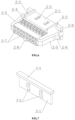
- a low-voltage connector comprises an adaptor 1 and a connector main body 2, the adaptor 1 is provided with a first connector head 1-1 and a second connector head 1-8 respectively at the front end and the rear end, the connector main body 2 is plug-connected to the second connector head 1-8, and the rear end of the connector main body 2 is connected to one or more signal lines.
- the signal lines may be connected to an electric-motor controller.
- the first connector head 1-1 may be a female connector head, which is connected to a male connector head, and the male connector head is in turn connected to a vehicle computer via the signal lines.
- the second connector head 1-8 is provided with first clipping slots 1-9 on the left side and the right side
- the connector main body 2 is provided with elastic arms 2-5 on the left side and the right side that are snap-fitted to the first clipping slots 1-9, to prevent the connector main body 2 from disengaging from the second connector head 1-8.
- the second connector head 1-8 is provided with second clipping slots 1-10 on the upper side and the lower side, and the connector main body 2 is provided with longitudinal convex strips 2-3 on the upper side and the lower side that are snap-fitted to the second clipping slots 1-10, to prevent the connector main body 2 from shaking in the left-and-right direction in the second connector head 1-8.
- Four second clipping slots 1-10 are provided, and correspondingly four longitudinal convex strips 2-3 are provided.
- the connector main body 2 when it is in the second connector head 1-8, does not easily disengage, and does not easily loosen, which obviously enhances the anti-vibration capacity.
- the second connector head 1-8 is provided with one slot 1-11 on the inner wall on one side in the length direction, and the connector main body 2 is correspondingly provided with one projection 2-8 on the outer wall in the length direction.
- the projection 2-8 and the slot 1-11 form a fool proofing structure, and after the projection 2-8 and the slot 1-11 have been matched the connector main body 2 is capable of being plug-connected to the second connector head 1-8.
- the first connector head 1-1 is provided with a plurality of matching poles 1-5 on the outer wall in the length direction.
- the matching poles 1-5 are for realizing matching when being plug-connected to another connector head (for example, the male connector head), and may further prevent loosening and disengaging.
- the first connector head 1-1 is provided with four matching poles 1-5 on the outer wall.
- the four matching poles 1-5 are not centering on the outer wall of the first connector head 1-1, but are proximal to the side where the engaging lug 1-7 is located. Such a structure can prevent reverse connection between the first connector head 1-1 and another connector head (for example, the male connector head), and is also a fool proofing structure.
- steps 1-2 are provided inside the first connector head 1-1 to gradually reduce internal dimensions.
- the steps 1-2 can realize guiding for plug connection, to facilitate the plug connection between the first connector head 1-1 and another connector head (for example, the male connector head).
- a plurality of circumferential positioning grooves 1-6 are provided on a periphery of the second connector head 1-8, and sealing rings are provided in the positioning grooves 1-6.
- the sealing rings can serve to seal and resist moisture.
- the second connector head 1-8 may block the wiring hole, in which case the sealing rings serve to seal the gap between the second connector head 1-8 and the wiring hole.
- the connector main body 2 is provided with stopping parts 2-9 at the rear end for limiting the insertion depth of the connector main body 2 into the second connector head 1-8, and the stopping parts 2-9 are provided with clearances for the elastic arms 2-5.
- a partition plate 1-3 is provided between the first connector head 1-1 and the second connector head 1-8, the partition plate 1-3 is provided with a pin array 1-4 that extend in a front-and-rear direction, a plurality of plug holes 2-7 are provided inside the connector main body 2, and after the connector main body 2 has been plug-connected to the second connector head 1-8, the front ends of the plug holes 2-7 are connected to the pin array 1-4, and the rear ends of the plug holes 2-7 are connected to the terminals of the signal lines, to realize the electrical connection inside the plug holes 2-7 between the pin array 1-4 and the signal lines.
- the connector main body 2 has totally two lines of the plug holes 2-7, which are arranged vertically, and can be used for the access of a plurality of leads.
- the connector main body 2 is provided with pressing blocks 2-4 on the outer wall in the length direction that correspond to the plug holes 2-7, and the pressing blocks 2-4 press the terminals of the signal lines inside the plug holes 2-7.
- the low-voltage connector according to the present embodiment by providing the snap-fitting structures having the different functions, has a good anti-vibration capacity and a reliable structure, and significantly improves the functions of preventing the low-voltage connector from falling due to vibration and preventing disconnection of the signal lines.
- the low-voltage connector further comprises a depressor 3, and the depressor 3 is inserted into the rear end of the connector main body 2, to depress and lock the signal lines into the rear ends of the plug holes 2-7.
- the depressor 3 comprises a sheet body 3-1, the sheet body is provided with clipping blocks 3-2 on one side, the connector main body 2 is correspondingly provided with clipping holes 2-2 on the outer wall in the length direction, and when the depressor 3 is inserted into the rear end of the connector main body 2, the clipping blocks 3-2 are snap-fitted to the clipping holes 2-2 on the connector main body 2.
- the sheet body 3-1 is provided with a stopping part 3-3 at the rear end for limiting the insertion depth of the depressor 3 into the connector main body 2.
- the depressor 3 can further prevent the terminals of the signal lines from disengaging from the connector main body 2.
- the other structures of the low-voltage connector of the present embodiment are the same as those of the first embodiment, and are not described repeatedly here.
Landscapes
- Details Of Connecting Devices For Male And Female Coupling (AREA)
Claims (8)
- Niederspannungsverbinder, umfassend einen Adapter (1) und einen Verbinderhauptkörper (2), wobei der Adapter (1) mit einem ersten Verbinderkopf (1-1) undeinem zweiten Verbinderkopf (1-8) jeweils an einem vorderen Ende und einem hinteren Ende versehen ist, wobei der Verbinderhauptkörper (2) ist mit dem zweiten Verbinderkopf (1-8) steckverbunden und ein hinteres Ende des Verbinderhauptkörpers (2) ist geeignet, mit einer oder mehreren Signalleitungen verbunden zu werden;der zweite Verbinderkopf (1-8) mit ersten Klemmschlitzen (1-9) auf einer linken Seite und einer rechten Seite versehen ist, und der Verbinderhauptkörper (2) mit elastischen Armen (2-5) auf einer linken Seite und einer rechten Seite versehen ist, die in die ersten Klemmschlitze (1-9) eingerastet sind, um zu verhindern, dass sich der Verbinderhauptkörper (2) von dem zweiten Verbinderkopf (1-8) löst;
undder zweite Verbinderkopf (1-8) mit zweiten Klemmschlitzen (1-10) auf einer oberen Seite und einer unteren Seite versehen ist, und der Verbinderhauptkörper (2) mit länglichen konvexen Streifen (2-3) auf einer oberen Seite und einer unteren Seite versehen ist, die in die zweiten Klemmschlitze (1-10) eingerastet sind, um zu verhindern, dass der Verbinderhauptkörper (2) im zweiten Verbinderkopf (1-8) nach links und rechts wackelt, wobeider Adapter (1) mit einer Eingriffslasche (1-7) versehen ist, dieauf einer linken Seite oder einer rechten Seite nach außen vorsteht, die Eingriffslasche mit einem Verbindungsloch versehen ist und der Adapter (1) geeignet ist,über die Eingriffslasche an einem Gehäuse einer anderen Komponente befestigt zu werden,der erste Verbinderkopf (1-1) mit einer Vielzahl von passenden Polen (1-5) an einer Außenwand in einer Längsrichtung versehen ist; und im Inneren des ersten Verbinderkopfes (1-1) Stufen vorgesehen sind, um die inneren Abmessungen allmählich zu verringern,die passenden Pole (1-5) nicht auf der Außenwand des ersten Verbinderkopfes (1-1) zentriert sind, sondern sich in der Nähe der Seite befinden, an der sich die Eingriffslasche (1-7) befindet. - Der Niederspannungsverbinder nach Anspruch 1, dadurch gekennzeichnet, dass: der zweite Verbinderkopf (1-8) mit einem Schlitz an einer Innenwand auf einer Seite in einer Längsrichtung versehen ist, der Verbinderhauptkörper (2) entsprechend mit einem Vorsprung (2-8) an einer Außenwand in einer Längsrichtung versehen ist, der Vorsprung (2-8) und der Schlitz eine narrensichere Struktur bilden, und nachdem der Vorsprung (2-8) und der Schlitz zusammengefügt worden sind, der
Verbinderhauptkörper (2) mit dem zweiten Verbinderkopf (1-8) zusammengesteckt werden kann. - Der Niederspannungsverbinder nach Anspruch 1, dadurch gekennzeichnet, dass: eine Vielzahl von umlaufenden Positionierungsnuten (1-6) an einem Umfang des zweiten Verbinderkopfes (1-8) vorgesehen sind, und Dichtungsringe in den Positionierungsnuten (1-6) vorgesehen sind.
- Der Niederspannungsverbinder nach Anspruch 1, dadurch gekennzeichnet, dass: die elastischen Arme (2-5) mit seitlich vorstehenden Klippblöcken (2-6) versehen sind, der zweite Verbinderkopf (1-8) entsprechend mit Klipplöchern (1-12) an Seitenwänden in einer Breitenrichtung versehen ist und nach dem Einstecken des Verbinderhauptkörpers (2) in den zweiten Verbinderkopf (1-8) die Klippblöcke (2-6) in die Klipplöcher (1-12) eingerastet sind; und
der Verbinderhauptkörper (2) mit Anschlagteilen (2-9) am hinteren Ende versehen ist, um eine Einstecktiefe des Verbinderhauptkörpers (2) in den zweiten Verbinderkopf (1-8) zu begrenzen, und die Anschlagteile (2-9) mit Freiräumen für die elastischen Arme (2-5) versehen sind. - Der Niederspannungsverbinder nach Anspruch 1, dadurch gekennzeichnet, dass: eine Trennplatte (1-3) zwischen dem ersten Verbinderkopf (1-1) und dem zweiten Verbinderkopf (1-8) vorgesehen ist, die Trennplatte (1-3) mit einer Anordnung von Stiften (1-4) versehen ist, die sich in einer vorderen und hinteren Richtung erstrecken, eine Vielzahl von Stecklöchern (2-7) innerhalb des Verbinderhauptkörpers (2) vorgesehen ist, und nachdem der Verbinderhauptkörper (2) mit dem zweiten Verbinderkopf (1-8) steckverbunden worden ist, sind die vorderen Enden der Steckerlöcher (2-7) mit der Stiftanordnung (1-4) verbunden, und die hinteren Enden der Steckerlöcher (2-7) sind mit den Anschlüssen der Signalleitungen verbunden, um eine elektrische Verbindung innerhalb der Steckerlöcher (2-7) zwischen der Stiftanordnung (1-4) und den Signalleitungen zu realisieren.
- Der Niederspannungsverbinder nach Anspruch 1, dadurch gekennzeichnet, dass: der Verbinderhauptkörper (2) mit Pressblöcken (2-4) an einer Außenwand in einer Längsrichtung versehen ist, die den Stecklöchern (2-7) entsprechen, und die Pressblöcke (2-4) die Anschlüsse der Signalleitungen innerhalb der Stecklöcher (2-7) drücken.
- Der Niederspannungsverbinder nach Anspruch 6, dadurch gekennzeichnet, dass: der Niederspannungsverbinder ferner einen Niederdrücker (3) umfasst und der Niederdrücker (3) in das hintere Ende des Verbinderhauptkörpers (2) eingeführt wird, um die Signalleitungen in die hinteren Enden der Stecklöcher (2-7) zu drücken und zu verriegeln.
- Der Niederspannungsverbinder nach Anspruch 7, dadurch gekennzeichnet, dass: der Niederdrücker (3) einen Blechkörper (3-1) umfasst, der Blechkörper (3-1) auf einer Seite mit einem Klippblock (2-6) versehen ist, der Verbinderhauptkörper (2) entsprechend mit einem Klipploch (2-2) auf einer Außenwand in der Längsrichtung versehen ist, und wenn der Niederdrücker (3) in das hintere Ende des Verbinderhauptkörpers (2) eingeführt wird, der Klippblock in das Klipploch (2-2) auf dem Verbinderhauptkörper (2) eingerastet wird; und
der Blechkörper (3-1) mit einem Anschlagteil (2-9) an einem hinteren Ende versehen ist, um eine Einführtiefe des Niederdrückers (3) in den Verbinderhauptkörper (2) zu begrenzen.
Applications Claiming Priority (1)
| Application Number | Priority Date | Filing Date | Title |
|---|---|---|---|
| CN201921578452.2U CN211088642U (zh) | 2019-09-20 | 2019-09-20 | 一种低压连接器 |
Publications (2)
| Publication Number | Publication Date |
|---|---|
| EP3796479A1 EP3796479A1 (de) | 2021-03-24 |
| EP3796479B1 true EP3796479B1 (de) | 2024-07-10 |
Family
ID=71629820
Family Applications (1)
| Application Number | Title | Priority Date | Filing Date |
|---|---|---|---|
| EP20195226.4A Active EP3796479B1 (de) | 2019-09-20 | 2020-09-09 | Niederspannungsverbinder |
Country Status (2)
| Country | Link |
|---|---|
| EP (1) | EP3796479B1 (de) |
| CN (1) | CN211088642U (de) |
Citations (2)
| Publication number | Priority date | Publication date | Assignee | Title |
|---|---|---|---|---|
| US3671921A (en) * | 1970-10-28 | 1972-06-20 | Amp Inc | Multi-contact electrical connector |
| JPH10241790A (ja) * | 1997-02-21 | 1998-09-11 | Yazaki Corp | コネクタハウジングの嵌合構造 |
Family Cites Families (7)
| Publication number | Priority date | Publication date | Assignee | Title |
|---|---|---|---|---|
| JPS5312458Y2 (de) * | 1972-12-25 | 1978-04-04 | ||
| US5588858A (en) * | 1995-03-15 | 1996-12-31 | Itt Corporation | Connector system with wedge and grommet retainer |
| JP2004253163A (ja) * | 2003-02-18 | 2004-09-09 | Yazaki Corp | 中継端子及びコネクタ |
| JP4748054B2 (ja) * | 2006-12-27 | 2011-08-17 | 住友電装株式会社 | コネクタ |
| KR200467383Y1 (ko) * | 2012-05-18 | 2013-06-12 | 이길석 | 진공커넥터 |
| CN104396096A (zh) * | 2012-07-03 | 2015-03-04 | 矢崎总业株式会社 | 连接器和连接端子 |
| TWI624115B (zh) * | 2017-06-07 | 2018-05-11 | Yung Li Co Ltd | Socket electrical connector, plug electrical connector and combinations thereof |
-
2019
- 2019-09-20 CN CN201921578452.2U patent/CN211088642U/zh active Active
-
2020
- 2020-09-09 EP EP20195226.4A patent/EP3796479B1/de active Active
Patent Citations (2)
| Publication number | Priority date | Publication date | Assignee | Title |
|---|---|---|---|---|
| US3671921A (en) * | 1970-10-28 | 1972-06-20 | Amp Inc | Multi-contact electrical connector |
| JPH10241790A (ja) * | 1997-02-21 | 1998-09-11 | Yazaki Corp | コネクタハウジングの嵌合構造 |
Also Published As
| Publication number | Publication date |
|---|---|
| EP3796479A1 (de) | 2021-03-24 |
| CN211088642U (zh) | 2020-07-24 |
Similar Documents
| Publication | Publication Date | Title |
|---|---|---|
| EP2686919B1 (de) | Hochspannungsverbinderanordnung | |
| EP0415489B1 (de) | Einbauverbinder für Kabelanordnung | |
| US5695368A (en) | Electrical terminal with protected locking lance and a connector therefor | |
| EP0955697B1 (de) | Wasserdichter Verbinder | |
| US7481674B2 (en) | Electrical connector | |
| KR100231122B1 (ko) | 개선된 배치 수단을 갖는 전기 커넥터 | |
| US5993255A (en) | Electrical connector with combination terminal guide and terminal position assurance member | |
| US20130171857A1 (en) | Electrical Connector | |
| HK1000400B (en) | Mountable connector for cable assembly | |
| US5520548A (en) | Vibration proof electrical connector housing | |
| US10886640B2 (en) | Conductive terminal and electrical connector | |
| EP0632536B1 (de) | Vibrationsbeständiges elektrisches Verbindergehäuse | |
| EP0125786A2 (de) | Elektrischer Verbindungszusammenbau | |
| US20070059967A1 (en) | Connector, a mating connector and a connector device | |
| US6773293B1 (en) | Cable end connector with locking member | |
| WO2012026972A1 (en) | Plug assembly | |
| US20030032321A1 (en) | Sealed connector | |
| EP0352087B1 (de) | Elektrischer Verbinder | |
| US5044982A (en) | Sealed bulkhead connector for vehicles | |
| US10128605B2 (en) | Connector | |
| US6071148A (en) | Seal retention member | |
| US20010012717A1 (en) | Connector | |
| US20070059973A1 (en) | Hot plug wire contact and connector assembly | |
| EP3796479B1 (de) | Niederspannungsverbinder | |
| US4647128A (en) | Electrical connector system with releasable latching |
Legal Events
| Date | Code | Title | Description |
|---|---|---|---|
| PUAI | Public reference made under article 153(3) epc to a published international application that has entered the european phase |
Free format text: ORIGINAL CODE: 0009012 |
|
| STAA | Information on the status of an ep patent application or granted ep patent |
Free format text: STATUS: THE APPLICATION HAS BEEN PUBLISHED |
|
| AK | Designated contracting states |
Kind code of ref document: A1 Designated state(s): AL AT BE BG CH CY CZ DE DK EE ES FI FR GB GR HR HU IE IS IT LI LT LU LV MC MK MT NL NO PL PT RO RS SE SI SK SM TR |
|
| AX | Request for extension of the european patent |
Extension state: BA ME |
|
| STAA | Information on the status of an ep patent application or granted ep patent |
Free format text: STATUS: REQUEST FOR EXAMINATION WAS MADE |
|
| 17P | Request for examination filed |
Effective date: 20210507 |
|
| RBV | Designated contracting states (corrected) |
Designated state(s): AL AT BE BG CH CY CZ DE DK EE ES FI FR GB GR HR HU IE IS IT LI LT LU LV MC MK MT NL NO PL PT RO RS SE SI SK SM TR |
|
| STAA | Information on the status of an ep patent application or granted ep patent |
Free format text: STATUS: EXAMINATION IS IN PROGRESS |
|
| 17Q | First examination report despatched |
Effective date: 20220916 |
|
| GRAP | Despatch of communication of intention to grant a patent |
Free format text: ORIGINAL CODE: EPIDOSNIGR1 |
|
| STAA | Information on the status of an ep patent application or granted ep patent |
Free format text: STATUS: GRANT OF PATENT IS INTENDED |
|
| RIC1 | Information provided on ipc code assigned before grant |
Ipc: H01R 107/00 20060101ALN20240123BHEP Ipc: H01R 24/20 20110101ALN20240123BHEP Ipc: H01R 13/506 20060101ALN20240123BHEP Ipc: H01R 31/06 20060101ALN20240123BHEP Ipc: H01R 13/52 20060101ALN20240123BHEP Ipc: H01R 13/436 20060101ALN20240123BHEP Ipc: H01R 13/64 20060101ALN20240123BHEP Ipc: H01R 13/631 20060101ALN20240123BHEP Ipc: H01R 13/74 20060101ALN20240123BHEP Ipc: H01R 13/627 20060101AFI20240123BHEP |
|
| INTG | Intention to grant announced |
Effective date: 20240207 |
|
| P01 | Opt-out of the competence of the unified patent court (upc) registered |
Effective date: 20240416 |
|
| GRAS | Grant fee paid |
Free format text: ORIGINAL CODE: EPIDOSNIGR3 |
|
| GRAA | (expected) grant |
Free format text: ORIGINAL CODE: 0009210 |
|
| STAA | Information on the status of an ep patent application or granted ep patent |
Free format text: STATUS: THE PATENT HAS BEEN GRANTED |
|
| AK | Designated contracting states |
Kind code of ref document: B1 Designated state(s): AL AT BE BG CH CY CZ DE DK EE ES FI FR GB GR HR HU IE IS IT LI LT LU LV MC MK MT NL NO PL PT RO RS SE SI SK SM TR |
|
| REG | Reference to a national code |
Ref country code: CH Ref legal event code: EP |
|
| REG | Reference to a national code |
Ref country code: DE Ref legal event code: R096 Ref document number: 602020033647 Country of ref document: DE |
|
| REG | Reference to a national code |
Ref country code: LT Ref legal event code: MG9D |
|
| REG | Reference to a national code |
Ref country code: NL Ref legal event code: MP Effective date: 20240710 |
|
| PG25 | Lapsed in a contracting state [announced via postgrant information from national office to epo] |
Ref country code: PT Free format text: LAPSE BECAUSE OF FAILURE TO SUBMIT A TRANSLATION OF THE DESCRIPTION OR TO PAY THE FEE WITHIN THE PRESCRIBED TIME-LIMIT Effective date: 20241111 |
|
| REG | Reference to a national code |
Ref country code: AT Ref legal event code: MK05 Ref document number: 1702879 Country of ref document: AT Kind code of ref document: T Effective date: 20240710 |
|
| PG25 | Lapsed in a contracting state [announced via postgrant information from national office to epo] |
Ref country code: NL Free format text: LAPSE BECAUSE OF FAILURE TO SUBMIT A TRANSLATION OF THE DESCRIPTION OR TO PAY THE FEE WITHIN THE PRESCRIBED TIME-LIMIT Effective date: 20240710 |
|
| PG25 | Lapsed in a contracting state [announced via postgrant information from national office to epo] |
Ref country code: PT Free format text: LAPSE BECAUSE OF FAILURE TO SUBMIT A TRANSLATION OF THE DESCRIPTION OR TO PAY THE FEE WITHIN THE PRESCRIBED TIME-LIMIT Effective date: 20241111 Ref country code: NL Free format text: LAPSE BECAUSE OF FAILURE TO SUBMIT A TRANSLATION OF THE DESCRIPTION OR TO PAY THE FEE WITHIN THE PRESCRIBED TIME-LIMIT Effective date: 20240710 |
|
| PG25 | Lapsed in a contracting state [announced via postgrant information from national office to epo] |
Ref country code: NO Free format text: LAPSE BECAUSE OF FAILURE TO SUBMIT A TRANSLATION OF THE DESCRIPTION OR TO PAY THE FEE WITHIN THE PRESCRIBED TIME-LIMIT Effective date: 20241010 |
|
| PG25 | Lapsed in a contracting state [announced via postgrant information from national office to epo] |
Ref country code: GR Free format text: LAPSE BECAUSE OF FAILURE TO SUBMIT A TRANSLATION OF THE DESCRIPTION OR TO PAY THE FEE WITHIN THE PRESCRIBED TIME-LIMIT Effective date: 20241011 Ref country code: FI Free format text: LAPSE BECAUSE OF FAILURE TO SUBMIT A TRANSLATION OF THE DESCRIPTION OR TO PAY THE FEE WITHIN THE PRESCRIBED TIME-LIMIT Effective date: 20240710 Ref country code: PL Free format text: LAPSE BECAUSE OF FAILURE TO SUBMIT A TRANSLATION OF THE DESCRIPTION OR TO PAY THE FEE WITHIN THE PRESCRIBED TIME-LIMIT Effective date: 20240710 |
|
| PG25 | Lapsed in a contracting state [announced via postgrant information from national office to epo] |
Ref country code: BG Free format text: LAPSE BECAUSE OF FAILURE TO SUBMIT A TRANSLATION OF THE DESCRIPTION OR TO PAY THE FEE WITHIN THE PRESCRIBED TIME-LIMIT Effective date: 20240710 |
|
| PG25 | Lapsed in a contracting state [announced via postgrant information from national office to epo] |
Ref country code: LV Free format text: LAPSE BECAUSE OF FAILURE TO SUBMIT A TRANSLATION OF THE DESCRIPTION OR TO PAY THE FEE WITHIN THE PRESCRIBED TIME-LIMIT Effective date: 20240710 |
|
| PG25 | Lapsed in a contracting state [announced via postgrant information from national office to epo] |
Ref country code: AT Free format text: LAPSE BECAUSE OF FAILURE TO SUBMIT A TRANSLATION OF THE DESCRIPTION OR TO PAY THE FEE WITHIN THE PRESCRIBED TIME-LIMIT Effective date: 20240710 Ref country code: IS Free format text: LAPSE BECAUSE OF FAILURE TO SUBMIT A TRANSLATION OF THE DESCRIPTION OR TO PAY THE FEE WITHIN THE PRESCRIBED TIME-LIMIT Effective date: 20241110 |
|
| PG25 | Lapsed in a contracting state [announced via postgrant information from national office to epo] |
Ref country code: HR Free format text: LAPSE BECAUSE OF FAILURE TO SUBMIT A TRANSLATION OF THE DESCRIPTION OR TO PAY THE FEE WITHIN THE PRESCRIBED TIME-LIMIT Effective date: 20240710 |
|
| PG25 | Lapsed in a contracting state [announced via postgrant information from national office to epo] |
Ref country code: ES Free format text: LAPSE BECAUSE OF FAILURE TO SUBMIT A TRANSLATION OF THE DESCRIPTION OR TO PAY THE FEE WITHIN THE PRESCRIBED TIME-LIMIT Effective date: 20240710 Ref country code: RS Free format text: LAPSE BECAUSE OF FAILURE TO SUBMIT A TRANSLATION OF THE DESCRIPTION OR TO PAY THE FEE WITHIN THE PRESCRIBED TIME-LIMIT Effective date: 20241010 |
|
| PG25 | Lapsed in a contracting state [announced via postgrant information from national office to epo] |
Ref country code: RS Free format text: LAPSE BECAUSE OF FAILURE TO SUBMIT A TRANSLATION OF THE DESCRIPTION OR TO PAY THE FEE WITHIN THE PRESCRIBED TIME-LIMIT Effective date: 20241010 Ref country code: PL Free format text: LAPSE BECAUSE OF FAILURE TO SUBMIT A TRANSLATION OF THE DESCRIPTION OR TO PAY THE FEE WITHIN THE PRESCRIBED TIME-LIMIT Effective date: 20240710 Ref country code: NO Free format text: LAPSE BECAUSE OF FAILURE TO SUBMIT A TRANSLATION OF THE DESCRIPTION OR TO PAY THE FEE WITHIN THE PRESCRIBED TIME-LIMIT Effective date: 20241010 Ref country code: LV Free format text: LAPSE BECAUSE OF FAILURE TO SUBMIT A TRANSLATION OF THE DESCRIPTION OR TO PAY THE FEE WITHIN THE PRESCRIBED TIME-LIMIT Effective date: 20240710 Ref country code: IS Free format text: LAPSE BECAUSE OF FAILURE TO SUBMIT A TRANSLATION OF THE DESCRIPTION OR TO PAY THE FEE WITHIN THE PRESCRIBED TIME-LIMIT Effective date: 20241110 Ref country code: HR Free format text: LAPSE BECAUSE OF FAILURE TO SUBMIT A TRANSLATION OF THE DESCRIPTION OR TO PAY THE FEE WITHIN THE PRESCRIBED TIME-LIMIT Effective date: 20240710 Ref country code: GR Free format text: LAPSE BECAUSE OF FAILURE TO SUBMIT A TRANSLATION OF THE DESCRIPTION OR TO PAY THE FEE WITHIN THE PRESCRIBED TIME-LIMIT Effective date: 20241011 Ref country code: FI Free format text: LAPSE BECAUSE OF FAILURE TO SUBMIT A TRANSLATION OF THE DESCRIPTION OR TO PAY THE FEE WITHIN THE PRESCRIBED TIME-LIMIT Effective date: 20240710 Ref country code: ES Free format text: LAPSE BECAUSE OF FAILURE TO SUBMIT A TRANSLATION OF THE DESCRIPTION OR TO PAY THE FEE WITHIN THE PRESCRIBED TIME-LIMIT Effective date: 20240710 Ref country code: BG Free format text: LAPSE BECAUSE OF FAILURE TO SUBMIT A TRANSLATION OF THE DESCRIPTION OR TO PAY THE FEE WITHIN THE PRESCRIBED TIME-LIMIT Effective date: 20240710 Ref country code: AT Free format text: LAPSE BECAUSE OF FAILURE TO SUBMIT A TRANSLATION OF THE DESCRIPTION OR TO PAY THE FEE WITHIN THE PRESCRIBED TIME-LIMIT Effective date: 20240710 |
|
| REG | Reference to a national code |
Ref country code: DE Ref legal event code: R097 Ref document number: 602020033647 Country of ref document: DE |
|
| PG25 | Lapsed in a contracting state [announced via postgrant information from national office to epo] |
Ref country code: RO Free format text: LAPSE BECAUSE OF FAILURE TO SUBMIT A TRANSLATION OF THE DESCRIPTION OR TO PAY THE FEE WITHIN THE PRESCRIBED TIME-LIMIT Effective date: 20240710 Ref country code: DK Free format text: LAPSE BECAUSE OF FAILURE TO SUBMIT A TRANSLATION OF THE DESCRIPTION OR TO PAY THE FEE WITHIN THE PRESCRIBED TIME-LIMIT Effective date: 20240710 Ref country code: SM Free format text: LAPSE BECAUSE OF FAILURE TO SUBMIT A TRANSLATION OF THE DESCRIPTION OR TO PAY THE FEE WITHIN THE PRESCRIBED TIME-LIMIT Effective date: 20240710 |
|
| PG25 | Lapsed in a contracting state [announced via postgrant information from national office to epo] |
Ref country code: MC Free format text: LAPSE BECAUSE OF FAILURE TO SUBMIT A TRANSLATION OF THE DESCRIPTION OR TO PAY THE FEE WITHIN THE PRESCRIBED TIME-LIMIT Effective date: 20240710 Ref country code: EE Free format text: LAPSE BECAUSE OF FAILURE TO SUBMIT A TRANSLATION OF THE DESCRIPTION OR TO PAY THE FEE WITHIN THE PRESCRIBED TIME-LIMIT Effective date: 20240710 |
|
| PG25 | Lapsed in a contracting state [announced via postgrant information from national office to epo] |
Ref country code: CZ Free format text: LAPSE BECAUSE OF FAILURE TO SUBMIT A TRANSLATION OF THE DESCRIPTION OR TO PAY THE FEE WITHIN THE PRESCRIBED TIME-LIMIT Effective date: 20240710 |
|
| PG25 | Lapsed in a contracting state [announced via postgrant information from national office to epo] |
Ref country code: SK Free format text: LAPSE BECAUSE OF FAILURE TO SUBMIT A TRANSLATION OF THE DESCRIPTION OR TO PAY THE FEE WITHIN THE PRESCRIBED TIME-LIMIT Effective date: 20240710 |
|
| REG | Reference to a national code |
Ref country code: CH Ref legal event code: PL |
|
| PLBE | No opposition filed within time limit |
Free format text: ORIGINAL CODE: 0009261 |
|
| STAA | Information on the status of an ep patent application or granted ep patent |
Free format text: STATUS: NO OPPOSITION FILED WITHIN TIME LIMIT |
|
| PG25 | Lapsed in a contracting state [announced via postgrant information from national office to epo] |
Ref country code: LU Free format text: LAPSE BECAUSE OF NON-PAYMENT OF DUE FEES Effective date: 20240909 |
|
| 26N | No opposition filed |
Effective date: 20250411 |
|
| REG | Reference to a national code |
Ref country code: BE Ref legal event code: MM Effective date: 20240930 |
|
| PG25 | Lapsed in a contracting state [announced via postgrant information from national office to epo] |
Ref country code: BE Free format text: LAPSE BECAUSE OF NON-PAYMENT OF DUE FEES Effective date: 20240930 Ref country code: IT Free format text: LAPSE BECAUSE OF NON-PAYMENT OF DUE FEES Effective date: 20240909 |
|
| PG25 | Lapsed in a contracting state [announced via postgrant information from national office to epo] |
Ref country code: CH Free format text: LAPSE BECAUSE OF NON-PAYMENT OF DUE FEES Effective date: 20240930 |
|
| PG25 | Lapsed in a contracting state [announced via postgrant information from national office to epo] |
Ref country code: IE Free format text: LAPSE BECAUSE OF NON-PAYMENT OF DUE FEES Effective date: 20240909 |
|
| PG25 | Lapsed in a contracting state [announced via postgrant information from national office to epo] |
Ref country code: SE Free format text: LAPSE BECAUSE OF FAILURE TO SUBMIT A TRANSLATION OF THE DESCRIPTION OR TO PAY THE FEE WITHIN THE PRESCRIBED TIME-LIMIT Effective date: 20240710 |
|
| PGFP | Annual fee paid to national office [announced via postgrant information from national office to epo] |
Ref country code: DE Payment date: 20250916 Year of fee payment: 6 |
|
| PGFP | Annual fee paid to national office [announced via postgrant information from national office to epo] |
Ref country code: GB Payment date: 20250919 Year of fee payment: 6 |
|
| PGFP | Annual fee paid to national office [announced via postgrant information from national office to epo] |
Ref country code: FR Payment date: 20250929 Year of fee payment: 6 |
|
| PG25 | Lapsed in a contracting state [announced via postgrant information from national office to epo] |
Ref country code: CY Free format text: LAPSE BECAUSE OF FAILURE TO SUBMIT A TRANSLATION OF THE DESCRIPTION OR TO PAY THE FEE WITHIN THE PRESCRIBED TIME-LIMIT; INVALID AB INITIO Effective date: 20200909 |
|
| PG25 | Lapsed in a contracting state [announced via postgrant information from national office to epo] |
Ref country code: HU Free format text: LAPSE BECAUSE OF FAILURE TO SUBMIT A TRANSLATION OF THE DESCRIPTION OR TO PAY THE FEE WITHIN THE PRESCRIBED TIME-LIMIT; INVALID AB INITIO Effective date: 20200909 |