EP3796867B1 - Support pour une prothèse de valvule cardiaque, agencement de stockage pour une prothèse de valvule cardiaque, et kit et procédé de sertissage - Google Patents
Support pour une prothèse de valvule cardiaque, agencement de stockage pour une prothèse de valvule cardiaque, et kit et procédé de sertissage Download PDFInfo
- Publication number
- EP3796867B1 EP3796867B1 EP18732477.7A EP18732477A EP3796867B1 EP 3796867 B1 EP3796867 B1 EP 3796867B1 EP 18732477 A EP18732477 A EP 18732477A EP 3796867 B1 EP3796867 B1 EP 3796867B1
- Authority
- EP
- European Patent Office
- Prior art keywords
- holder
- armature
- heart valve
- arched
- annular member
- Prior art date
- Legal status (The legal status is an assumption and is not a legal conclusion. Google has not performed a legal analysis and makes no representation as to the accuracy of the status listed.)
- Active
Links
Images




Classifications
-
- A—HUMAN NECESSITIES
- A61—MEDICAL OR VETERINARY SCIENCE; HYGIENE
- A61F—FILTERS IMPLANTABLE INTO BLOOD VESSELS; PROSTHESES; DEVICES PROVIDING PATENCY TO, OR PREVENTING COLLAPSING OF, TUBULAR STRUCTURES OF THE BODY, e.g. STENTS; ORTHOPAEDIC, NURSING OR CONTRACEPTIVE DEVICES; FOMENTATION; TREATMENT OR PROTECTION OF EYES OR EARS; BANDAGES, DRESSINGS OR ABSORBENT PADS; FIRST-AID KITS
- A61F2/00—Filters implantable into blood vessels; Prostheses, i.e. artificial substitutes or replacements for parts of the body; Appliances for connecting them with the body; Devices providing patency to, or preventing collapsing of, tubular structures of the body, e.g. stents
- A61F2/0095—Packages or dispensers for prostheses or other implants
-
- A—HUMAN NECESSITIES
- A61—MEDICAL OR VETERINARY SCIENCE; HYGIENE
- A61F—FILTERS IMPLANTABLE INTO BLOOD VESSELS; PROSTHESES; DEVICES PROVIDING PATENCY TO, OR PREVENTING COLLAPSING OF, TUBULAR STRUCTURES OF THE BODY, e.g. STENTS; ORTHOPAEDIC, NURSING OR CONTRACEPTIVE DEVICES; FOMENTATION; TREATMENT OR PROTECTION OF EYES OR EARS; BANDAGES, DRESSINGS OR ABSORBENT PADS; FIRST-AID KITS
- A61F2/00—Filters implantable into blood vessels; Prostheses, i.e. artificial substitutes or replacements for parts of the body; Appliances for connecting them with the body; Devices providing patency to, or preventing collapsing of, tubular structures of the body, e.g. stents
- A61F2/02—Prostheses implantable into the body
- A61F2/24—Heart valves ; Vascular valves, e.g. venous valves; Heart implants, e.g. passive devices for improving the function of the native valve or the heart muscle; Transmyocardial revascularisation [TMR] devices; Valves implantable in the body
- A61F2/2412—Heart valves ; Vascular valves, e.g. venous valves; Heart implants, e.g. passive devices for improving the function of the native valve or the heart muscle; Transmyocardial revascularisation [TMR] devices; Valves implantable in the body with soft flexible valve members, e.g. tissue valves shaped like natural valves
- A61F2/2418—Scaffolds therefor, e.g. support stents
-
- A—HUMAN NECESSITIES
- A61—MEDICAL OR VETERINARY SCIENCE; HYGIENE
- A61F—FILTERS IMPLANTABLE INTO BLOOD VESSELS; PROSTHESES; DEVICES PROVIDING PATENCY TO, OR PREVENTING COLLAPSING OF, TUBULAR STRUCTURES OF THE BODY, e.g. STENTS; ORTHOPAEDIC, NURSING OR CONTRACEPTIVE DEVICES; FOMENTATION; TREATMENT OR PROTECTION OF EYES OR EARS; BANDAGES, DRESSINGS OR ABSORBENT PADS; FIRST-AID KITS
- A61F2/00—Filters implantable into blood vessels; Prostheses, i.e. artificial substitutes or replacements for parts of the body; Appliances for connecting them with the body; Devices providing patency to, or preventing collapsing of, tubular structures of the body, e.g. stents
- A61F2/02—Prostheses implantable into the body
- A61F2/24—Heart valves ; Vascular valves, e.g. venous valves; Heart implants, e.g. passive devices for improving the function of the native valve or the heart muscle; Transmyocardial revascularisation [TMR] devices; Valves implantable in the body
- A61F2/2427—Devices for manipulating or deploying heart valves during implantation
-
- A—HUMAN NECESSITIES
- A61—MEDICAL OR VETERINARY SCIENCE; HYGIENE
- A61F—FILTERS IMPLANTABLE INTO BLOOD VESSELS; PROSTHESES; DEVICES PROVIDING PATENCY TO, OR PREVENTING COLLAPSING OF, TUBULAR STRUCTURES OF THE BODY, e.g. STENTS; ORTHOPAEDIC, NURSING OR CONTRACEPTIVE DEVICES; FOMENTATION; TREATMENT OR PROTECTION OF EYES OR EARS; BANDAGES, DRESSINGS OR ABSORBENT PADS; FIRST-AID KITS
- A61F2/00—Filters implantable into blood vessels; Prostheses, i.e. artificial substitutes or replacements for parts of the body; Appliances for connecting them with the body; Devices providing patency to, or preventing collapsing of, tubular structures of the body, e.g. stents
- A61F2/95—Instruments specially adapted for placement or removal of stents or stent-grafts
- A61F2/9522—Means for mounting a stent or stent-graft onto or into a placement instrument
-
- A—HUMAN NECESSITIES
- A61—MEDICAL OR VETERINARY SCIENCE; HYGIENE
- A61F—FILTERS IMPLANTABLE INTO BLOOD VESSELS; PROSTHESES; DEVICES PROVIDING PATENCY TO, OR PREVENTING COLLAPSING OF, TUBULAR STRUCTURES OF THE BODY, e.g. STENTS; ORTHOPAEDIC, NURSING OR CONTRACEPTIVE DEVICES; FOMENTATION; TREATMENT OR PROTECTION OF EYES OR EARS; BANDAGES, DRESSINGS OR ABSORBENT PADS; FIRST-AID KITS
- A61F2/00—Filters implantable into blood vessels; Prostheses, i.e. artificial substitutes or replacements for parts of the body; Appliances for connecting them with the body; Devices providing patency to, or preventing collapsing of, tubular structures of the body, e.g. stents
- A61F2/95—Instruments specially adapted for placement or removal of stents or stent-grafts
- A61F2/9522—Means for mounting a stent or stent-graft onto or into a placement instrument
- A61F2/9524—Iris-type crimpers
Definitions
- the disclosure relates to a holder for manipulating implantable medical devices such as a heart valve prosthesis including a radially contractible armature and a prosthetic heart valve carried by the armature, during a pre-operative procedure preceding the implantation of the heart valve prosthesis.
- implantable medical devices such as a heart valve prosthesis
- a radially contractible armature and a prosthetic heart valve carried by the armature, during a pre-operative procedure preceding the implantation of the heart valve prosthesis.
- a heart valve prosthesis should be stored in a sterile environment in order to maintain its integrity and in order to prevent air from being trapped in the structure of the prosthesis.
- prostheses may need to be crimped i.e. radially collapsed and coupled to a delivery instrument to be delivered to an implantation site, for example in a minimally invasive or percutaneous procedure.
- Crimping an implantable medical device can present many important issues. While many crimping devices with different features have been devised to facilitate the crimping operation, such a step may remain rather delicate and complex to perform.
- the delivery instruments are provided with angular indicia (for example markers which are intended to identify the commissures of an aortic or tricuspid valve) intended to aid the practitioner in correctly positioning the prosthesis at the implantation site.
- EP 2 644 158 A1 discloses a kit for manipulating implantable medical device such as heart valve prosthesis, has holder element that is configured to support implantable medical device, and is extended axially towards tubular structure of medical device.
- the present invention relates to a holder for a heart valve prosthesis as defined in claim 1. Embodiments of the invention are recited in the dependent claims.
- a first example of a holder for a heart valve prosthesis comprising a radially contractible armature and a prosthetic valve carried by said armature.
- the holder including an annular member having a longitudinal axis and comprising a plurality of supporting formations, said supporting formations protruding radially inwardly of said annular member, and a locking member configured for coupling with said annular member.
- each supporting formation includes a coupling profile configured for engaging the armature of a heart valve prosthesis, the coupling profile being configured to prevent the displacement of the armature along said longitudinal axis and being configured to prevent rotation of the armature around the longitudinal axis, while leaving the armature unconstrained in a radially inward direction.
- the locking member is configured to removably mate with the annular member to provide a radial constraint to the armature in a radially inward direction at the supporting formations.
- annular member defines a lumen, the supporting formations protruding inwardly of said lumen.
- annular member includes an angular reference member configured for a sliding coupling with a fixed rectilinear guide, the angular reference member having a predetermined position relative to the supporting formations.
- each coupling profile is a coupling interface for an arched strut comprising a cylindrical wall, and an arched track provided on the cylindrical wall and configured for receiving an arched strut, each coupling interface facing radially inwardly of said annular member.
- at least one of said supporting formations includes a guide member for guiding said locking member upon mating to the annular member.
- said arched track includes a tooth protruding from the cylindrical wall and radially inwardly of the annular member, and a pair of arched protrusions arranged on opposite sides of said tooth.
- said locking member is a hub member configured for mating to the annular member coaxially to the longitudinal axis thereof and including a cylindrical portion configured to settle among the supporting formations when the locking member is mated to the annular member.
- the locking member further includes a guide portion, particularly provided on a rim, configured for slidably coupling with the guide members of the supporting formations.
- a twelfth example according to any of the previous examples further including a heart valve prosthesis having a radially contractible armature and a prosthetic heart valve carried by said armature.
- the armature including an annular part, and a pattern of arched struts carried by said annular part. Said pattern of arched struts having proximal ends connected to said annular part, and distal ends spaced axially from the proximal ends and opposite said annular part (106). Where, distal portions of the arched struts engage corresponding coupling profiles of the supporting formations.
- a fourteenth example of a holder for a heart valve prosthesis comprising a radially contractible armature and a prosthetic valve carried by said armature, the holder (1) including:
- each coupling feature provides a coupling interface for an arched strut comprising:
- At least one of said supporting formations includes a guide member for guiding said locking member upon mating to the annular member.
- said locking member is a hub member configured for mating to the annular member coaxially to the longitudinal axis thereof and including a cylindrical portion configured to settle among the supporting formations when the locking member is mated to the annular member.
- annular member includes an angular reference member configured for a sliding coupling with a fixed rectilinear guide, the angular reference member having a predetermined position relative to the supporting formations.
- a nineteenth example of a prosthetic heart valve storage kit including:
- a twentieth example of a crimping kit comprising:
- a twenty-first example of a method of crimping a heart valve prosthesis comprising a radially contractible armature and a prosthetic valve carried by said armature, the method comprising:
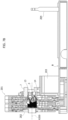
- reference number 1 designates a holder for a heart valve prosthesis according to various embodiments herein.
- the holder 1 may be used for supporting an implantable medical device such as a heart valve prosthesis including a radially contractible armature and a prosthetic valve carried by the armature.
- An exemplary heart valve prosthesis is disclosed, e.g., in PCT application no. PCT/IB2018/053640 filed on even date herewith and in the name of the same Applicant.
- the holder 1 includes an annular member 2 having a longitudinal axis X1 (which also corresponds to the holder axis) and comprising a plurality of supporting formations 3, the supporting formations 3 protruding radially inwardly of the annular member 2, and a locking member 4 configured for coupling with the annular member 2.
- Each supporting formation 3 includes a coupling feature configured for engaging the armature of a heart valve prosthesis supported by the holder 1, wherein the coupling feature is configured to limit the displacement of the armature along the longitudinal axis X1 while leaving the armature unconstrained in a radially inward direction.
- the locking member 4 is configured to removably mate with the annular member 2 to provide a radial constraint to the armature in a radially inward direction at the supporting formations 3.
- the locking member 4 removably couples to the annular member 2, wherein coupling occurs through an axial sliding of the locking member 4 along the axis X1 and into the supporting formations 3, so that the locking member 4 is located among the supporting formations 3 and at least partially overlaps the same when mated to the annular member 2.
- the annular member 2 includes a peripheral rim 5 wherefrom the supporting formations 3 protrude radially inwardly in a spoke-like fashion.
- the peripheral rim 5 defines a lumen 6 for the prosthesis, wherein the supporting formations 3 protrude into the lumen 6.
- the number and location of the supporting formations 3 may generally depend on the specific features of the heart valve prosthesis to be coupled to the holder 1.
- the supporting formations are in the number of three with even angular offset (120 degrees), bearing witness to the holder 1 being configured for coupling to the armature of an aortic heart valve prosthesis.
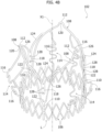
- the heart valve prosthesis 100 includes an armature 102 for anchorage of the valve prosthesis at an implantation site.
- the armature 102 defines a lumen for the passage of the blood flow and has a longitudinal axis X1.
- the prosthesis 100 also includes a set of prosthetic valve leaflets 104 supported by the armature 102 and configured to move, under the action of blood flow, which has a main flow direction roughly corresponding to that of the axis X1, in a radially divaricated condition to enable the flow of blood through the lumen in a first direction, and in a radially contracted condition, in which the valve leaflets 4 co-operate with one another and block the flow of blood through the prosthesis 1 in the direction opposite the first direction.
- leaflet coaptation This is commonly referred to as leaflet coaptation.
- the prosthetic leaflets 4 may be in any number compatible with operation as a replacement heart valve.
- the set includes a pair of leaflets.
- the set includes three prosthetic valve leaflets 4 (e.g. for an aortic valve prosthesis).
- the set may include four leaflets 4.
- the armature 102 includes an annular part 106, and a pattern of arched struts 108 carried by the annular part 106.
- the annular part 106 has a structure which can expand from a radially contracted condition, associated to delivery of the prosthesis to implantation site, to a radially expanded condition wherein the prosthesis is withheld at the implantation site.
- the annular part may have a mesh structure including an annular pattern of multiple strut clusters (cells) having polygonal shape (hexagonal, rhomboidal, etc.).
- the annular part is covered by a cuff such as the sealing cuff SC to provide sealing at the implantation site, the cuff being arranged outside of the lumen of the armature 102.
- the cuff may be sewn or stitched to the annular part 106.
- the cuff SC may be integral with the set of prosthetic valve leaflets 104.
- the pattern of arched struts 108 includes proximal ends 110 connected to the annular part 106, and distal ends 112 spaced axially from the proximal ends 110 and arranged at an end of the armature 102 opposite the annular part 106.
- the distal ends 112 coincide with distal ends of the armature 102, and in embodiments where the distal end of the armature 102 coincides with a distal end of the prosthesis 100 as a whole, the distal ends 112 coincide with a distal end of the prosthesis as well.
- the armature 102 further includes a plurality of sets 114 of anchoring formations 116 configured to protrude radially outwardly of the annular part 106, each set 114 being supported by at least one of the annular part 106 and a corresponding arched strut 108, and a plurality of support posts 118, each supported by adjacent arched struts 108.
- the sets 114 of anchoring formations 116 alternate with the support posts 118 around the longitudinal axis X1.
- the support posts 118 are cantilevered to adjacent arched struts 108 and are configured as fixing locations for the prosthetic valve, specifically for the pleat formations PF at the commissural points of the valve.
- Each arched strut 8 extends from a first proximal end 110, to a distal end 112, then to a second proximal end 110 in a valley-peak-valley sequence, wherein valleys are located at the proximal ends 110, and peaks are located at the distal ends 112.
- the pattern of arched struts includes three adjacent and preferably identical arched struts 108 (such as in the figures).
- the pattern of arched struts 108 includes distal portions 120 located at the distal ends 112, and inter-strut portions 122 located at the proximal ends 110.
- the distal portions 120 may be shaped so as to provide a marked local variation in the shape of the strut, for example by exhibiting a C-shape as shown in the figure.
- the distal portions 120 may provide coupling locations for other devices such as a valve holder or a hub of a carrier portion of a delivery catheter.
- the distal portions 120 may be provided as closed-loop structures such as eyes or eyelets.
- the inter-strut portions 122 are essentially V-shaped and are defined by the roots of the adjacent arched struts departing from the same proximal end 110.
- the inter strut portions 122 may exhibit a Y-shape such as, for instance, that shown in the figure wherein each inter-strut portion 122 extends through the mesh of the annular part 106.
- a U-shape may be envisaged for the inter-strut portions 122.
- the mesh of the annular part 106 is provided as a sequence of rhomboidal strut clusters (cells) sequentially connected to each other at endpoints of a diagonal line (typically the shortest diagonal) and exhibiting accordingly an identical circular pattern of free ends on opposite sides of a circumference extending through the sequence of the connection points.
- the Y-shaped inter-strut portion 122 is thus integrally formed at a selected connection point between two adjacent rhomboidal strut clusters, and may extend no further than the proximal end of the armature 102.
- the support posts 118 are angularly arranged at an inter-strut location, i.e. a circumferential location arranged at an area where an inter-strut portion 122 (as well as a proximal end 110 shared by two adjacent arched struts 108) is provided.
- the support posts may be provided as cantilevered to both the adjacent arched struts 8 intervening at an inter-strut portion 122 via a first and a second cantilever struts 124, 126, each connected to a corresponding one of said adjacent arched struts 8 as shown in the figures.
- the cantilever struts 124, 126 merge into each corresponding post 118 starting from locations on respective arched strut 108 approximately halfway through the portion of the arched strut 108 extending from a proximal end 110 to a distal end 112.
- the connection points at which the Y-shaped or U-shaped inter-strut portion 122 is formed may be chosen so that the same portions are evenly spaced (angular-wise) around the axis X1.
- the armature 102 comprises three arched struts 108, three posts 118 spaced 120° around the axis X1, and three sets 114, so that the sequence around the axis X1 is post 118 - set 114 - post 118 - set 114 - post 118 - set 114 (in this sense, even the struts 108 and the sets 114 do follow a 120 degree-like distribution).
- the three sets 114 include each a pair of anchoring formations 116, wherein each set 114 (and accordingly each anchoring formation 116) extends bridge-wise between the annular part 106 and the corresponding arched strut 108.
- each supporting formation includes a radial tab member 7 and a circumferential tab member 8 which is arranged at a radially inward end of the tab member 7.
- the circumferential tab member 8 may be generally orthogonal to the tab member 7.
- the circumferential tab member 8 carries the coupling feature of the supporting formation 3, wherein the coupling feature is generally indicated as 9 in the figures.
- the coupling feature 9 may be a coupling profile. Owing to the location on the tabs 8, each coupling profile or feature faces radially inwardly of the annular member 2.
- the coupling profile 9 is a recessed profile and is configured for receiving a portion - such as a strut - of the armature of the prosthesis to at least partially secure the prosthesis to the holder.
- each coupling profile 9 is a coupling interface comprising a cylindrical wall 10, which may be a radially innermost wall of the tab 8, an arched track 11 ( Figure 2B ) provided on the cylindrical wall 10 and configured for receiving an arched strut 108 of the prosthesis 100, particularly a distal portion 120 thereof.
- the arched track 11 may receive any arched strut of a valve armature, and not necessarily those in the prosthesis 100.
- the arched track 11 is a recessed track.
- the arched track ( figure 2B ) may include a tooth 12 protruding from the cylindrical wall 10 radially inwardly of the annular member 2 (i.e. protruding into the lumen 6), and a pair of arched protrusions 13, 14 arranged on opposite sides of the tooth 12 and likewise protruding radially inwardly of the annular member 2.
- the arched protrusions 13, 14 are spaced from one another in correspondence of the tooth 12 so as to provide a gap 15 therebetween.
- the gap 15 may serve as an additional coupling location to the arched track 11, especially when the arched strut of the prosthesis armature exhibits a hairpin-like shape that is able to penetrate (in a snap-fit fashion) through the interspace 15.
- the coupling profiles may be provided as reliefs instead of recesses.
- the reliefs couple with matching features of the armature of the heart valve prosthesis radially outwardly of the same.
- the mesh of radially contractible/expandable annular portion of the armature maybe an example of such matching features.
- the prosthesis 100 (this applies to any prosthesis having a contractible armature featuring arched struts including arched or looped portions of the armature mesh) is coupled to the holder 1 so that the arched struts 108 - and particularly the distal portions 120 thereof - are received in the arched track 11 astride of the tooth 12.
- the axial displacement of the armature 102 is limited or substantially prevented, any rotational movement around the axis X1 is likewise prevented (thus providing a predetermined angular orientation of the prosthesis 100 relative to the holder 1), while radial displacement inwardly of the annular member 2 (i.e.
- At least one - and preferably all - of the supporting formations includes a guide member for guiding the locking member 4 upon coupling to the annular member 2.
- These guide members may be provided, in embodiments such as that depicted in the figures, by the very radial tabs 7 which can act as rectilinear guides for the locking member 4, which may be provided with a correspondingly mating profile to the tabs 7.
- the guide member may be a member separate from the supporting formations, especially in those embodiments wherein the guide members are grouped in a pattern located on the rim 5 of the annular member 2 in a position angularly offset from the pattern of supporting formations 3.
- the guide members on the annular element are configured for guiding the locking member 4 in a direction parallel to the longitudinal axis X1.
- the locking member 4 is provided as a hub member configured for mating to the annular member 2 coaxially to the longitudinal axis X1 thereof and including a cylindrical portion 16 configured to settle among the supporting formations 3 to provide a radial constraint to the armature of the prosthesis 100, particularly a radial constraint inwardly of the annular member 2.
- the locking member 4 provides a radial locking action against contraction of the prosthesis: being the latter axially and rotationally locked by the supporting formations 3, and likewise radially locked by the same formations relative to the expansion of the armature 102, the sole degree of freedom not taken away by the annular member 2 consists of the radial contraction of the armature 102. In this sense, the positioning of the locking member 4 with the hub portion 16 among the supporting formations 3 takes away this last degree of freedom as the armature gets sandwiched between the supporting formations and the hub portion of the locking member 4.
- the locking member 4 may further include a guide portion, particularly provided on a rim 17, which configured for slidably coupling with the guide members of the supporting formations 3, particularly with the tabs 7
- the rim 17 may include in one embodiments a plurality of notches configured for mating with the radial tabs 7 to provide a sliding coupling therewith.
- the rim 17 is configured to abut on an axial end portion of the supporting formations 3, particularly onto the tabs 8, to limit the penetration of the locking member 4 among the formations 3 and correctly position the locking member relative to the same.
- the annular member 2 includes an angular reference member 19 configured for a sliding coupling with a fixed rectilinear guide.
- the angular reference member 19 has a predetermined angular position relative to the supporting formations 3, which in turn have an arrangement specific to the structure of the prosthesis they carry (hence a predetermined angular position relative to the prosthesis itself, as per the foregoing description). In this way the angular reference member 19 is univocally representative of the angular orientation of the prosthesis around the axis X1.
- the angular reference member 19 is provided on the periphery of the annular member 2, particularly as apportion of the rim 5, and is configured as a slider member of a prismatic guide.
- the angular reference member 19 includes two side radial tabs 20, 21 and a cylindrical wall 22 located between the tabs 20, 21.
- the angular reference members - while maintaining the slider features - may be provided as a triangular or otherwise polygonal notch on the rim 5.
- the holder 100 may be part of a storage kit S for a heart valve prosthesis 100 comprising a radially contractible armature (such as the armature 102) and a prosthetic valve carried by said armature.
- a radially contractible armature such as the armature 102
- a prosthetic valve carried by said armature.
- the storage kit S comprises the holder 1 and the prosthesis 100 coupled to the holder 1, i.e. coupled to the supporting formations 3 so to be axially and rotationally locked by the annular member 2, and furthermore radially locked both by the annular member 2 and the locking member 4.
- the storage kit S further comprises a container J (so called "jar") filled with a preservation solution and closed by a cap C with the interposition of a seal SL.
- jar container J
- the holder 1 with the prosthesis 100 attached thereto is arranged in the container J with the heart valve prosthesis 100 immersed in the preservation solution.
- the interior of the container J is provided with axial ribs R configured to engage notches on the periphery of the rim 5 to guide the holder into the container J and held it against rotation, as well as to set the axial position of the holder within the container J.
- reference number 200 designates a crimping kit according to various embodiments.
- the crimping kit 200 includes a crimping instrument 201 with a crimping orifice 202 having a longitudinal axis X200, the crimping instrument being preferably mounted on a base member B, a rectilinear guide 203 oriented parallel to the longitudinal axis X200, the holder 1 with the heart valve prosthesis 100 coupled thereto.
- the crimping kit 200 may come provided with the holder 1 (with the attached prosthesis 100) in the storage kit S, so to provide a stand-alone package that can be deployed in the operational theater when necessary.
- the kit 200 may also include a support post 204 for the shaft of a delivery instrument which, during crimping and loading operations of the prosthesis 100, is positioned coaxially to the axis X200 for loading of the prosthesis.
- the post 204 may be provided as a sliding element capable of a linear motion X204+/- in a direction parallel to the axis X200, to accommodate for different delivery instrument lengths.
- the crimping kit 200 allows for a rapid, fail-safe crimping procedure of the prosthesis 100 based on the features of the holder 1.
- the holder 1 may be grabbed by the practitioner (or by assistant medical personnel in the operational theater) and coupled to the rectilinear guide 203.
- the angular reference member 19 on the annular element 2 is mated with the rectilinear guide 203 so as to assemble a prismatic guide, wherein the angular reference member 19 (and the holder 1 as a whole, accordingly) acts as a slider, while the guide 203 acts as a guide member for the slider.
- the holder 1 is mated to the guide 203 so as to present the prosthesis 100 to the crimping orifice 202 of the crimping instrument 201, while the holder 1 is located in a "trailing" position relative to the prosthesis.
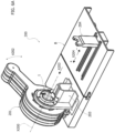
- the holder 1 with the prosthesis 100 attached thereto may be then advanced towards the crimping orifice 202 along the guide 203 (displacement X203 in Figure 6A ) so to insert the heart valve prosthesis 100 into the crimping orifice 202, and set the armature 102 in a position that allows the same to be later contracted by crimping members of the instrument 200 ( figure 6B ), subject to removal of locking member 4.
- the locking member 4 is still coupled to the annular member 2 to ensure that during the whole insertion of the heart valve prosthesis 100 into the crimping orifice 202, the prosthesis does not experience undesired displacements that result in a misplacement thereof.
- the prosthesis 100 maintains the positioning imparted thereto at the time of coupling of the same to the holder 1.
- the supporting formations 3 with the coupling features or profiles 9 preventing the prosthesis 100 from axial translation, from rotation around the axis X1, as well as from radial outward expansion.
- the angular reference member 19 is univocally representative of the actual orientation of the prosthesis 100 around the axis X1.
- the angular reference member 19 thus eliminates any risk of angular misplacement of the prosthesis 100, moreover in a way that only requires a very easy operation such as mating a slider to a guide. Additionally, the provision of the locking member 4 avoids any displacement of the valve prosthesis 100 during manipulation.
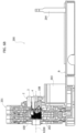
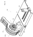
- the prosthesis 100 Once the prosthesis 100 is fully into the crimping orifice 202, the prosthesis shall be cleared relative to the radial contraction. This is made, in various embodiments, by removal of the locking member 4 from the annular member 2 of the holder 1 ( Figures 7A , 7B ), for example by axial sliding thereof away from the annular member (e.g. in a direction opposite that of X203).
- Other defeat mechanisms may of course be envisaged for the locking member 4, for example the same may be provided as a variable diameter member, wherein the variation in diameter may be controlled via a push button on the locking member itself, in a way at least roughly similar to releasable joints with radially slidable studs or pins.
- Removal of the locking member 4 thus removes the constraint that prevents the prosthesis 100 from being radially collapsed/contracted. Additionally, removal of the locking member 4 also clears the lumen 6 for insertion of the carrier portion of the delivery instrument, which at this point may be set on the post 204 and into the crimping orifice 202.
- the removal of the locking member 4 may advantageously be provided just prior to installation of the delivery instrument and subsequent crimping of the prosthesis to ensure maximum positional stability and loading of the prosthesis 100 onto the instrument, essentially to avoid any accidental misplacement of the prosthesis 100 relative to the crimping instrument 200 prior to the crimping and loading of the same onto the delivery instrument.
- the prosthesis 100 is then crimped (e.g. by rotation of the handle of the crimping instrument 200 in the direction ⁇ 201 in Figure 8 ) and loaded into the carrier portion of the delivery instrument.
- the annular member 2 remains into the crimping orifice, as the same does not provide any hindrance to the crimping action, which is a radial contraction action.
- crimping of the heart valve prosthesis 100 results in a disengagement of the armature 102 from the supporting formations 3 due to a migration of the portion of the armature 102 received in the coupling feature or profile 9 radially inwardly and off the coupling profile itself (e.g. off the arched track 11) .
- the annular member 2 may then optionally be removed from the crimping instrument 200, e.g. by sliding it away from the crimping orifice 202 along the guide 203 in a direction opposite to X203, and over the delivery instrument shaft. Once the latter is lifted too away from the crimping orifice 202, the annular element 2 may then be removed from the delivery instrument shaft.
- the annular member 2 is left in place on the guide 203 and taken away after takeoff of the delivery instrument.
- the angular reference member 19 and the guide 203 may be dispensed with, instead relying on more conventional angular positioning techniques, for example a mating notch/pin pair on the annular member 2 and the crimping instrument 200.
- these embodiments only perform slightly less efficiently in terms of angular positioning of the holder relative to the crimping instrument, requiring i.e. a minor manual alignment operation (e.g. a rotation until the mating notch/pin pair clicks into engagement) instead of coming already angularly positioned and ready to insert as with the holder 1 in the embodiments pictured by the figures.
Landscapes
- Health & Medical Sciences (AREA)
- Cardiology (AREA)
- Engineering & Computer Science (AREA)
- Biomedical Technology (AREA)
- Heart & Thoracic Surgery (AREA)
- Transplantation (AREA)
- Oral & Maxillofacial Surgery (AREA)
- Vascular Medicine (AREA)
- Life Sciences & Earth Sciences (AREA)
- Animal Behavior & Ethology (AREA)
- General Health & Medical Sciences (AREA)
- Public Health (AREA)
- Veterinary Medicine (AREA)
- Prostheses (AREA)
Claims (15)
- Support (1) pour une prothèse de valvule cardiaque (100) comprenant une armature (102) radialement contractible et une valvule prothétique portée par ladite armature (102), le support (1) comprenant :un organe annulaire (2) ayant un axe longitudinal (X1) et comprenant une pluralité de formations de soutien (3) ; etun organe de verrouillage (4) configuré pour se coupler audit organe annulaire (2),dans lequel :chaque formation de soutien (3) comprend un élément de couplage (9) configuré pour s'engager avec l'armature (102) d'une prothèse de valvule cardiaque (100), de manière à empêcher le déplacement de l'armature (102) le long dudit axe longitudinal et la rotation de l'armature (102) autour de l'axe longitudinal (X1), etl'organe de verrouillage (4) est configuré pour s'accoupler de manière amovible avec l'organe annulaire (2) pour fournir une contrainte radiale à l'armature dans une direction radialement vers l'intérieur au niveau des formations de soutien (3).
- Support (1) selon la revendication 1, dans lequel chaque élément de couplage (9) fournit une interface de couplage pour un jambage arqué (108, 120) comprenant :une paroi cylindrique (10) ; etune piste arquée (11) prévue sur la paroi cylindrique (10) et configurée pour recevoir un jambage arqué (108),chaque interface de couplage étant orientée radialement vers l'intérieur dudit organe annulaire (2).
- Support (1) de la revendication 1, dans lequel au moins l'une desdites formations de soutien (3) comprend un organe de guidage (7) pour guider ledit organe de verrouillage (4) lors de l'accouplement à l'organe annulaire (2).
- Support (1) de la revendication 1, dans lequel ledit organe de verrouillage (4) est un organe de raccord configuré pour s'accoupler à l'organe annulaire (2) de manière coaxiale à son axe longitudinal (X1) et comprenant une partie cylindrique (16) configurée pour s'installer entre les formations de soutien (3) lorsque l'organe de verrouillage (4) est accouplé à l'organe annulaire (2).
- Support (1) de la revendication 1, dans lequel l'organe annulaire (2) comprend un organe de référence angulaire (19) configuré pour un couplage coulissant avec un guide rectiligne fixe (203), l'organe de référence angulaire (19) ayant une position prédéterminée par rapport aux formations de soutien (3).
- Support (1) selon la revendication 2, dans lequel l'organe annulaire définit une lumière (5), les formations de soutien (3) faisant saillie vers l'intérieur de ladite lumière (5).
- Support (1) selon la revendication 5, dans lequel l'organe de référence angulaire (19) est prévu sur la périphérie dudit organe annulaire (2) et est configuré comme un organe coulissant d'un guide prismatique.
- Support (1) de la revendication 2, dans lequel ladite piste arquée (11) comprend :une dent (12) faisant saillie à partir de la paroi cylindrique (10) et radialement vers l'intérieur de l'organe annulaire (2) ; etune paire de saillies arquées (13, 14) agencées sur les côtés opposés de ladite dent (12).
- Support (1) de la revendication 8, dans lequel lesdites saillies arquées (13, 14) sont espacées l'une de l'autre en correspondance avec ladite dent (12).
- Support (1) de la revendication 4, dans lequel l'organe de verrouillage (4) comprend en outre une partie de guidage, particulièrement prévue sur une collerette (17), configurée pour se coupler de manière coulissante aux organes de guidage (7) des formations de soutien (3).
- Support (1) de la revendication 10, dans lequel la partie de guidage (17) est en outre configurée pour venir en butée contre une partie d'extrémité axiale des formations de soutien (3).
- Support (1) de l'une des revendications précédentes, comprenant en outre une prothèse de valvule cardiaque (100) ayant une armature (102) radialement contractible et une valvule cardiaque prothétique portée par ladite armature (102), l'armature (102) comprenant :une partie annulaire (106) ; etun motif de jambages arqués (108) porté par ladite partie annulaire (106), ledit motif de jambages arqués (108) ayant des extrémités proximales (110) reliées à ladite partie annulaire, et des extrémités distales (112) espacées axialement des extrémités proximales (110) et opposées à ladite partie annulaire (106),dans lequel des parties distales (120) des jambages arqués (108) s'engagent avec des profils de couplage (9) correspondants des formations de soutien (3).
- Support (1) de la revendication 12, dans lequel les parties distales (120) des jambages arqués (108) sont reçues dans les pistes arquées (11) des profils de couplage (9).
- Support (1) de l'une des revendications précédentes, dans lequel lesdites formations de soutien (3) font saillie radialement vers l'intérieur dudit organe annulaire (2), et dans lequel l'élément de couplage (9) laisse l'armature (102) sans contrainte dans une direction radialement vers l'intérieur.
- Kit de stockage (S) de valvule cardiaque prothétique comprenant :un support (1) selon les revendications 1 à 14 ;une prothèse de valvule cardiaque (100) comprenant une armature (102) radialement contractible et une valvule prothétique portée par ladite armature (102), la prothèse de valvule cardiaque étant couplée au support (1) au niveau des formations de soutien (3) ; etun récipient (J) rempli d'une solution de conservation, le support (1) étant agencé dans le récipient avec la prothèse de valvule cardiaque (100) immergée dans la solution de conservation.
Applications Claiming Priority (1)
| Application Number | Priority Date | Filing Date | Title |
|---|---|---|---|
| PCT/IB2018/053645 WO2019224580A1 (fr) | 2018-05-23 | 2018-05-23 | Support pour une prothèse de valvule cardiaque, agencement de stockage pour une prothèse de valvule cardiaque, et kit et procédé de sertissage |
Publications (2)
| Publication Number | Publication Date |
|---|---|
| EP3796867A1 EP3796867A1 (fr) | 2021-03-31 |
| EP3796867B1 true EP3796867B1 (fr) | 2024-12-25 |
Family
ID=62683378
Family Applications (1)
| Application Number | Title | Priority Date | Filing Date |
|---|---|---|---|
| EP18732477.7A Active EP3796867B1 (fr) | 2018-05-23 | 2018-05-23 | Support pour une prothèse de valvule cardiaque, agencement de stockage pour une prothèse de valvule cardiaque, et kit et procédé de sertissage |
Country Status (7)
| Country | Link |
|---|---|
| US (1) | US11992397B2 (fr) |
| EP (1) | EP3796867B1 (fr) |
| JP (1) | JP7074929B2 (fr) |
| CN (1) | CN112437648B (fr) |
| AU (1) | AU2018424862B2 (fr) |
| CA (1) | CA3101166A1 (fr) |
| WO (1) | WO2019224580A1 (fr) |
Families Citing this family (7)
| Publication number | Priority date | Publication date | Assignee | Title |
|---|---|---|---|---|
| US11096781B2 (en) | 2016-08-01 | 2021-08-24 | Edwards Lifesciences Corporation | Prosthetic heart valve |
| WO2019224577A1 (fr) | 2018-05-23 | 2019-11-28 | Sorin Group Italia S.R.L. | Prothèse de valvule cardiaque |
| MX2023001747A (es) | 2020-08-24 | 2023-04-25 | Edwards Lifesciences Corp | Recubrimiento de globo para un dispositivo de suministro de una válvula cardíaca protésica expandible. |
| WO2023007228A1 (fr) | 2021-07-29 | 2023-02-02 | Corcym S.R.L. | Systèmes et méthodes de pliage et de chargement d'un dispositif prothétique |
| KR20240055007A (ko) * | 2021-10-12 | 2024-04-26 | 메릴 라이프 사이언시즈 프라이빗 리미티드 | 인공 판막용 맞교차 정렬 시스템 및 정렬 방법 |
| WO2023124546A1 (fr) * | 2021-12-30 | 2023-07-06 | 杭州启明医疗器械股份有限公司 | Support, boîte de conditionnement, et système de conditionnement pour valve prothétique |
| WO2025212741A1 (fr) * | 2024-04-03 | 2025-10-09 | Boston Scientific Scimed, Inc. | Appareil et procédés de chargement d'un implant de valve cardiaque de remplacement |
Citations (3)
| Publication number | Priority date | Publication date | Assignee | Title |
|---|---|---|---|---|
| US20120290079A1 (en) * | 2011-05-12 | 2012-11-15 | Edwards Lifesciences Corporation | Mitral heart valve holder and storage system |
| WO2016046599A1 (fr) * | 2014-09-24 | 2016-03-31 | Sorin Group Italia S.R.L. | Support pour prothèses de valvule cardiaque, agencement de stockage correspondant, instrument de pose, et kit |
| WO2017139421A1 (fr) * | 2016-02-08 | 2017-08-17 | Blockwise Engineering Llc | Appareil de compression radiale et procédé de compression incrémentielle d'un article utilisant celui-ci |
Family Cites Families (127)
| Publication number | Priority date | Publication date | Assignee | Title |
|---|---|---|---|---|
| US3363442A (en) | 1965-05-25 | 1968-01-16 | North American Aviation Inc | Tube tapering device |
| GB1127325A (en) | 1965-08-23 | 1968-09-18 | Henry Berry | Improved instrument for inserting artificial heart valves |
| GB2083362B (en) | 1977-12-29 | 1982-11-24 | Yeshiva University Albert Eins | Disposable heart valve unit |
| US4473077A (en) | 1982-05-28 | 1984-09-25 | United States Surgical Corporation | Surgical stapler apparatus with flexible shaft |
| US4683883A (en) | 1985-04-30 | 1987-08-04 | Hemex Scientific, Inc. | Two-piece heart valve holder/rotator |
| US5042161A (en) | 1985-10-07 | 1991-08-27 | Joseph Hodge | Intravascular sizing method and apparatus |
| US5522884A (en) | 1993-02-19 | 1996-06-04 | Medtronic, Inc. | Holder for adjustable mitral & tricuspid annuloplasty rings |
| US5360014A (en) | 1993-11-10 | 1994-11-01 | Carbomedics, Inc. | Sizing apparatus for heart valve with supra annular suture ring |
| US5489296A (en) | 1993-12-17 | 1996-02-06 | Autogenics | Heart valve measurement tool |
| DE69431122T2 (de) | 1993-12-22 | 2003-03-27 | St. Jude Medical, Inc. | Herzklappenhalter |
| US5698307A (en) | 1994-02-04 | 1997-12-16 | Fabrite Laminating Corp. | Quadlaminate fabric for surgical gowns and drapes |
| US5560487A (en) | 1994-07-29 | 1996-10-01 | Carbomedics, Inc. | Holder and packaging for bioprosthetic heart valve |
| US5776187A (en) | 1995-02-09 | 1998-07-07 | St. Jude Medical, Inc. | Combined holder tool and rotator for a prosthetic heart valve |
| US6214043B1 (en) | 1995-05-24 | 2001-04-10 | St. Jude Medical, Inc. | Releasable hanger for heart valve prosthesis low profile holder |
| AU5951996A (en) | 1995-06-07 | 1996-12-30 | Heartport, Inc. | Less invasive devices and methods for treatment of cardiac valves |
| WO1996040006A1 (fr) | 1995-06-07 | 1996-12-19 | St. Jude Medical, Inc. | Dispositif de calibrage reglable destine aux anneaux du coeur |
| US5626604A (en) | 1995-12-05 | 1997-05-06 | Cordis Corporation | Hand held stent crimping device |
| US5693066A (en) | 1995-12-21 | 1997-12-02 | Medtronic, Inc. | Stent mounting and transfer device and method |
| WO1997024989A1 (fr) | 1996-01-04 | 1997-07-17 | Shelhigh, Inc. | Prothese de valvule cardiaque et procede de fabrication associe |
| JP3822908B2 (ja) | 1996-01-05 | 2006-09-20 | エドワーズ ライフサイエンシーズ コーポレイション | 大動脈弁補綴物のサイズ決定用栓子 |
| US6402780B2 (en) | 1996-02-23 | 2002-06-11 | Cardiovascular Technologies, L.L.C. | Means and method of replacing a heart valve in a minimally invasive manner |
| US5672169A (en) | 1996-04-10 | 1997-09-30 | Medtronic, Inc. | Stent mounting device |
| US5885228A (en) | 1996-05-08 | 1999-03-23 | Heartport, Inc. | Valve sizer and method of use |
| US5669919A (en) | 1996-08-16 | 1997-09-23 | Medtronic, Inc. | Annuloplasty system |
| US6123712A (en) | 1996-08-23 | 2000-09-26 | Scimed Life Systems, Inc. | Balloon catheter with stent securement means |
| US5800531A (en) | 1996-09-30 | 1998-09-01 | Baxter International Inc. | Bioprosthetic heart valve implantation device |
| US5972016A (en) | 1997-04-22 | 1999-10-26 | Advanced Cardiovascular Systems, Inc. | Stent crimping device and method of use |
| US5810873A (en) | 1997-07-15 | 1998-09-22 | Advanced Cardiovascular Systems, Inc. | Stent crimping tool and method of use |
| US6769161B2 (en) | 1997-10-16 | 2004-08-03 | Scimed Life Systems, Inc. | Radial stent crimper |
| US6024737A (en) | 1998-02-25 | 2000-02-15 | Advanced Cardiovascular Systems, Inc. | Stent crimping device |
| US6202272B1 (en) | 1998-02-26 | 2001-03-20 | Advanced Cardiovascular Systems, Inc. | Hand-held stent crimping device |
| US6009614A (en) | 1998-04-21 | 2000-01-04 | Advanced Cardiovascular Systems, Inc. | Stent crimping tool and method of use |
| US5931851A (en) | 1998-04-21 | 1999-08-03 | Advanced Cardiovascular Systems, Inc. | Method and apparatus for rubber-tube crimping tool with premount stent |
| US6141855A (en) | 1998-04-28 | 2000-11-07 | Advanced Cardiovascular Systems, Inc. | Stent crimping tool and method of use |
| US6019739A (en) | 1998-06-18 | 2000-02-01 | Baxter International Inc. | Minimally invasive valve annulus sizer |
| US6092273A (en) | 1998-07-28 | 2000-07-25 | Advanced Cardiovascular Systems, Inc. | Method and apparatus for a stent crimping device |
| US6051002A (en) | 1998-10-09 | 2000-04-18 | Advanced Cardiovascular Systems, Inc. | Stent crimping device and method of use |
| US5951540A (en) | 1998-10-22 | 1999-09-14 | Medtronic, Inc. | Device and method for mounting stents |
| US6125523A (en) | 1998-11-20 | 2000-10-03 | Advanced Cardiovascular Systems, Inc. | Stent crimping tool and method of use |
| CA2329213C (fr) | 1999-01-22 | 2005-08-09 | Gore Enterprise Holdings, Inc. | Combinaison de stent et de prothese endovasculaire a profil mince |
| AU771852B2 (en) | 1999-01-26 | 2004-04-01 | Edwards Lifesciences Corporation | Anatomical orifice sizers and methods of orifice sizing |
| US7563267B2 (en) | 1999-04-09 | 2009-07-21 | Evalve, Inc. | Fixation device and methods for engaging tissue |
| ATE366557T1 (de) | 1999-04-28 | 2007-08-15 | St Jude Medical | Aortenherzklappenprothesenmess- und - markierungsvorrichtung |
| DE29911694U1 (de) | 1999-07-06 | 1999-08-26 | Jostra Medizintechnik AG, 72145 Hirrlingen | Universalmeßschablone für Annuloplastieringe |
| DE19943844A1 (de) | 1999-09-13 | 2001-03-15 | Basf Ag | Verfahren zur Herstellung von Carbonsäurechloriden |
| US6350281B1 (en) | 1999-09-14 | 2002-02-26 | Edwards Lifesciences Corp. | Methods and apparatus for measuring valve annuluses during heart valve-replacement surgery |
| US6387117B1 (en) | 1999-09-22 | 2002-05-14 | Scimed Life Systems, Inc. | Stent crimping system |
| US6352547B1 (en) | 1999-09-22 | 2002-03-05 | Scimed Life Systems, Inc. | Stent crimping system |
| US6360577B2 (en) | 1999-09-22 | 2002-03-26 | Scimed Life Systems, Inc. | Apparatus for contracting, or crimping stents |
| US6678962B1 (en) | 1999-11-17 | 2004-01-20 | Cardiomend Llc | Device and method for assessing the geometry of a heart valve |
| US6598307B2 (en) | 1999-11-17 | 2003-07-29 | Jack W. Love | Device and method for assessing the geometry of a heart valve |
| US6481262B2 (en) | 1999-12-30 | 2002-11-19 | Advanced Cardiovascular Systems, Inc. | Stent crimping tool |
| AU2001229476A1 (en) | 2000-01-14 | 2001-07-24 | Viacor Incorporated | Tissue annuloplasty band and apparatus and method for fashioning, sizing and implanting the same |
| US6309383B1 (en) | 2000-01-20 | 2001-10-30 | Isostent, Inc. | Stent crimper apparatus with radiation shied |
| US6454799B1 (en) | 2000-04-06 | 2002-09-24 | Edwards Lifesciences Corporation | Minimally-invasive heart valves and methods of use |
| US6510722B1 (en) | 2000-05-10 | 2003-01-28 | Advanced Cardiovascular Systems, Inc. | Stent crimping tool for producing a grooved crimp |
| US6629350B2 (en) | 2000-06-08 | 2003-10-07 | Tom Motsenbocker | Stent crimping apparatus and method |
| WO2002001999A2 (fr) | 2000-06-30 | 2002-01-10 | Viacor, Incorporated | Procede et appareil permettant d'effectuer une intervention sur une valvule cardiaque |
| AU2000267004A1 (en) | 2000-08-03 | 2002-02-18 | Fortimedix B.V. | Device for crimping a stent onto a catheter delivery system |
| EP1179322A3 (fr) | 2000-08-09 | 2004-02-25 | BIOTRONIK Mess- und Therapiegeräte GmbH & Co Ingenieurbüro Berlin | Procédé et dispositif de sertissage de prothèses endovasculaires |
| US6955689B2 (en) | 2001-03-15 | 2005-10-18 | Medtronic, Inc. | Annuloplasty band and method |
| WO2002076700A1 (fr) | 2001-03-26 | 2002-10-03 | Machine Solutions, Inc. | Technologie de pliage d'un ballonnet |
| FR2824765B1 (fr) | 2001-05-16 | 2003-09-26 | Mg3 | Dispositif d'assemblage par sertissage de pieces de liaison sur des moyens a assembler |
| US6893460B2 (en) | 2001-10-11 | 2005-05-17 | Percutaneous Valve Technologies Inc. | Implantable prosthetic valve |
| FR2833833B1 (fr) | 2001-12-21 | 2004-01-30 | Oreal | Composition pour la teinture d'oxydation des fibres keratiniques comprenant un acide ether carboxylique oxyalkylene, un polymere associatif et un alcool gras insature |
| US7189258B2 (en) | 2002-01-02 | 2007-03-13 | Medtronic, Inc. | Heart valve system |
| DE20205557U1 (de) | 2002-04-10 | 2002-07-04 | Weidmüller Interface GmbH & Co., 32760 Detmold | Crimpvorrichtung |
| US6966924B2 (en) | 2002-08-16 | 2005-11-22 | St. Jude Medical, Inc. | Annuloplasty ring holder |
| JP2004154164A (ja) | 2002-11-01 | 2004-06-03 | Mizuho Co Ltd | 多自由度型処置具 |
| US7152452B2 (en) | 2002-12-26 | 2006-12-26 | Advanced Cardiovascular Systems, Inc. | Assembly for crimping an intraluminal device and method of use |
| US20040193259A1 (en) | 2003-03-25 | 2004-09-30 | Shlomo Gabbay | Sizing apparatus for cardiac prostheses and method of using same |
| US7510573B2 (en) | 2003-03-25 | 2009-03-31 | Shlomo Gabbay | Sizing apparatus |
| US7367984B2 (en) | 2003-05-07 | 2008-05-06 | Medtronic, Inc. | Methods and apparatus for sizing fresh donor heart valves |
| US20040225356A1 (en) | 2003-05-09 | 2004-11-11 | Frater Robert W. | Flexible heart valve |
| US7007396B2 (en) | 2003-05-29 | 2006-03-07 | Plc Medical Systems, Inc. | Replacement heart valve sizing device |
| DE10345718A1 (de) | 2003-10-01 | 2005-05-04 | Henkel Kgaa | Kohäsionsverminderte Bindemittel, deren Herstellung und Verwendung in ablösbaren Montageklebern |
| US7258698B2 (en) | 2003-10-17 | 2007-08-21 | Medtronic, Inc. | Prosthetic heart valve sizer assembly with flexible sizer body |
| US7069794B2 (en) | 2003-11-10 | 2006-07-04 | Machine Solutions, Inc. | Radial expansion force measurement technology |
| US7186265B2 (en) | 2003-12-10 | 2007-03-06 | Medtronic, Inc. | Prosthetic cardiac valves and systems and methods for implanting thereof |
| US7316147B2 (en) | 2004-01-29 | 2008-01-08 | Boston Scientific Scimed, Inc. | Apparatuses for crimping and loading of intraluminal medical devices |
| US7225518B2 (en) | 2004-02-23 | 2007-06-05 | Boston Scientific Scimed, Inc. | Apparatus for crimping a stent assembly |
| US8206439B2 (en) | 2004-02-23 | 2012-06-26 | International Heart Institute Of Montana Foundation | Internal prosthesis for reconstruction of cardiac geometry |
| ITTO20040135A1 (it) | 2004-03-03 | 2004-06-03 | Sorin Biomedica Cardio Spa | Protesi valvolare cardiaca |
| US7021114B2 (en) | 2004-04-16 | 2006-04-04 | Boston Scientific Scimed, Inc. | Stent crimper |
| DE102004019254B8 (de) | 2004-04-16 | 2005-11-03 | Qualimed Innovative Medizinprodukte Gmbh | Vorrichtung zur Reduzierung des Durchmessers eines Stents |
| US7143625B2 (en) | 2004-04-16 | 2006-12-05 | Boston Scientific Scimed, Inc. | Stent crimper |
| US20050267529A1 (en) | 2004-05-13 | 2005-12-01 | Heber Crockett | Devices, systems and methods for tissue repair |
| EP1768630B1 (fr) | 2004-06-16 | 2015-01-07 | Machine Solutions, Inc. | Sertisseur de prothèses endovasculaires |
| JP2008506497A (ja) | 2004-07-19 | 2008-03-06 | セント ジュード メディカル インコーポレイテッド | 心臓弁の支持体および蓋裏打ちシステムならびに方法 |
| ITTO20050074A1 (it) | 2005-02-10 | 2006-08-11 | Sorin Biomedica Cardio Srl | Protesi valvola cardiaca |
| US7316148B2 (en) | 2005-02-15 | 2008-01-08 | Boston Scientific Scimed, Inc. | Protective sheet loader |
| BRPI0520071A2 (pt) | 2005-04-29 | 2009-04-14 | Arterial Remodelling Technolog | fixação de stent |
| US7681430B2 (en) | 2005-05-25 | 2010-03-23 | Boston Scientific Scimed, Inc. | Method and apparatus for reducing a stent |
| US20100071203A1 (en) | 2005-06-23 | 2010-03-25 | Schleuniger Holding Ag | Crimping machine for different crimping and pressing processes, in particular for cable assembly |
| US8790396B2 (en) | 2005-07-27 | 2014-07-29 | Medtronic 3F Therapeutics, Inc. | Methods and systems for cardiac valve delivery |
| US7530253B2 (en) | 2005-09-09 | 2009-05-12 | Edwards Lifesciences Corporation | Prosthetic valve crimping device |
| US20070213813A1 (en) | 2005-12-22 | 2007-09-13 | Symetis Sa | Stent-valves for valve replacement and associated methods and systems for surgery |
| US9717468B2 (en) | 2006-01-10 | 2017-08-01 | Mediguide Ltd. | System and method for positioning an artificial heart valve at the position of a malfunctioning valve of a heart through a percutaneous route |
| AU2007272962B2 (en) | 2006-07-11 | 2012-09-27 | Covidien Lp | Biocompatible hydrogels |
| US8454684B2 (en) * | 2006-08-02 | 2013-06-04 | Medtronic, Inc. | Heart valve holder for use in valve implantation procedures |
| WO2008089365A2 (fr) | 2007-01-19 | 2008-07-24 | The Cleveland Clinic Foundation | Méthode de mise en place d'une valve cardiovasculaire |
| US20080262603A1 (en) | 2007-04-23 | 2008-10-23 | Sorin Biomedica Cardio | Prosthetic heart valve holder |
| US8006535B2 (en) | 2007-07-12 | 2011-08-30 | Sorin Biomedica Cardio S.R.L. | Expandable prosthetic valve crimping device |
| US8747458B2 (en) * | 2007-08-20 | 2014-06-10 | Medtronic Ventor Technologies Ltd. | Stent loading tool and method for use thereof |
| CA2703665C (fr) | 2007-10-25 | 2016-05-10 | Symetis Sa | Stents, stents a valve et procedes et systemes de mise en place de ceux-ci |
| AU2009205739B2 (en) | 2008-01-16 | 2014-09-25 | St. Jude Medical, Inc. | Delivery and retrieval systems for collapsible/expandable prosthetic heart valves |
| US20090192603A1 (en) | 2008-01-25 | 2009-07-30 | Medtronic, Inc. | Adjustable Sizer Devices for Minimally Invasive Cardiac Surgery |
| EP2594230B1 (fr) | 2008-02-29 | 2021-04-28 | Edwards Lifesciences Corporation | Elément extensible servant à déployer une prothèse |
| US8652202B2 (en) | 2008-08-22 | 2014-02-18 | Edwards Lifesciences Corporation | Prosthetic heart valve and delivery apparatus |
| US8715207B2 (en) | 2009-03-19 | 2014-05-06 | Sorin Group Italia S.R.L. | Universal valve annulus sizing device |
| EP2410947B1 (fr) | 2009-03-26 | 2015-05-20 | Sorin Group USA, Inc. | Dispositifs de dimensionnement d'annuloplastie pour opérations à invasion minimale |
| FR2943906B1 (fr) | 2009-04-03 | 2013-03-22 | Univ Pierre Et Marie Curie Paris 6 | Instrument chirurgical. |
| US7967138B2 (en) | 2009-04-06 | 2011-06-28 | Medtronic Vascular, Inc. | Packaging systems for percutaneously deliverable bioprosthetic valves |
| US8468667B2 (en) | 2009-05-15 | 2013-06-25 | Jenavalve Technology, Inc. | Device for compressing a stent |
| WO2010130789A1 (fr) * | 2009-05-15 | 2010-11-18 | Jenavalve Technology Inc. | Dispositif de compression d'endoprothèse ainsi que système et procédé pour le chargement d'une endoprothèse dans un système d'administration médicale |
| RU140821U1 (ru) | 2009-11-02 | 2014-05-20 | Симетис Са | Аортальный биопротез и системы для его доставки в место имплантации |
| US8641757B2 (en) * | 2010-09-10 | 2014-02-04 | Edwards Lifesciences Corporation | Systems for rapidly deploying surgical heart valves |
| AU2011300644B2 (en) | 2010-09-10 | 2015-08-20 | Symetis Sa | Valve replacement devices and a system comprising the valve replacement device and a delivery device therefor |
| WO2012106491A1 (fr) | 2011-02-02 | 2012-08-09 | St. Jude Medical, Inc. | Système de chargement d'une valvule cardiaque pliable dans un dispositif de pose. |
| DE202011000848U1 (de) | 2011-04-12 | 2011-06-09 | Aesculap AG, 78532 | Steuerungsvorrichtung |
| EP2520251A1 (fr) | 2011-05-05 | 2012-11-07 | Symetis SA | Procédé et appareil pour compresser des valvules d'endoprothèse |
| EP2644158A1 (fr) * | 2012-03-28 | 2013-10-02 | Sorin Group Italia S.r.l. | Kit pour la manipulation de dispositifs médicaux implantables |
| US9308569B2 (en) * | 2013-02-01 | 2016-04-12 | Medtronic, Inc. | Devices and methods for crimping and loading a medical device into a delivery system |
| US20140260097A1 (en) | 2013-03-15 | 2014-09-18 | Edwards Lifesciences Corporation | Automated crimping of transcatheter heart valves |
| US9585752B2 (en) | 2014-04-30 | 2017-03-07 | Edwards Lifesciences Corporation | Holder and deployment system for surgical heart valves |
| US9987000B2 (en) | 2014-12-18 | 2018-06-05 | Ethicon Llc | Surgical instrument assembly comprising a flexible articulation system |
| US10123892B2 (en) | 2015-05-28 | 2018-11-13 | St. Jude Medical, Cardiology Division, Inc. | System for loading a collapsible heart valve having a leaflet restraining member |
-
2018
- 2018-05-23 EP EP18732477.7A patent/EP3796867B1/fr active Active
- 2018-05-23 CN CN201880095764.XA patent/CN112437648B/zh active Active
- 2018-05-23 JP JP2021515293A patent/JP7074929B2/ja active Active
- 2018-05-23 AU AU2018424862A patent/AU2018424862B2/en active Active
- 2018-05-23 CA CA3101166A patent/CA3101166A1/fr active Pending
- 2018-05-23 US US17/057,511 patent/US11992397B2/en active Active
- 2018-05-23 WO PCT/IB2018/053645 patent/WO2019224580A1/fr not_active Ceased
Patent Citations (3)
| Publication number | Priority date | Publication date | Assignee | Title |
|---|---|---|---|---|
| US20120290079A1 (en) * | 2011-05-12 | 2012-11-15 | Edwards Lifesciences Corporation | Mitral heart valve holder and storage system |
| WO2016046599A1 (fr) * | 2014-09-24 | 2016-03-31 | Sorin Group Italia S.R.L. | Support pour prothèses de valvule cardiaque, agencement de stockage correspondant, instrument de pose, et kit |
| WO2017139421A1 (fr) * | 2016-02-08 | 2017-08-17 | Blockwise Engineering Llc | Appareil de compression radiale et procédé de compression incrémentielle d'un article utilisant celui-ci |
Also Published As
| Publication number | Publication date |
|---|---|
| WO2019224580A1 (fr) | 2019-11-28 |
| AU2018424862A1 (en) | 2020-12-10 |
| US11992397B2 (en) | 2024-05-28 |
| CN112437648A (zh) | 2021-03-02 |
| AU2018424862B2 (en) | 2024-05-02 |
| US20210196442A1 (en) | 2021-07-01 |
| EP3796867A1 (fr) | 2021-03-31 |
| CA3101166A1 (fr) | 2019-11-28 |
| CN112437648B (zh) | 2024-08-09 |
| JP2021523817A (ja) | 2021-09-09 |
| JP7074929B2 (ja) | 2022-05-24 |
Similar Documents
| Publication | Publication Date | Title |
|---|---|---|
| AU2018424862B2 (en) | A holder for a heart valve prosthesis, a storage arrangement for a heart valve prosthesis, and a crimping kit and method | |
| US9114010B2 (en) | Kit for the manipulation of implantable medical devices | |
| EP3787561B1 (fr) | Dispositifs de sertissage d'implants prothétiques | |
| US10653509B2 (en) | Holder for heart valve prostheses, corresponding storage arrangement, delivery instrument and kit | |
| US9144493B2 (en) | Valve prosthesis deployment assembly and method | |
| EP3796872B1 (fr) | Dispositif pour l'administration in-situ de prothèses de valvules cardiaques | |
| WO2012158187A1 (fr) | Dispositif d'annuloplastie à tire-bouchon | |
| CN112384173B (zh) | 用于可植入假体的加载系统及相关的加载方法 | |
| US11701214B2 (en) | Prosthetic heart valve packaging and attachment assembly | |
| US10390951B2 (en) | Clocking valve retainer | |
| CN110662511B (zh) | 具有可折叠保持器的假体心脏瓣膜 | |
| WO2002034121A9 (fr) | Outil entraineur avec plusieurs couches de pignons menants pour attaches d'une prothese cardiaque |
Legal Events
| Date | Code | Title | Description |
|---|---|---|---|
| STAA | Information on the status of an ep patent application or granted ep patent |
Free format text: STATUS: UNKNOWN |
|
| STAA | Information on the status of an ep patent application or granted ep patent |
Free format text: STATUS: THE INTERNATIONAL PUBLICATION HAS BEEN MADE |
|
| PUAI | Public reference made under article 153(3) epc to a published international application that has entered the european phase |
Free format text: ORIGINAL CODE: 0009012 |
|
| STAA | Information on the status of an ep patent application or granted ep patent |
Free format text: STATUS: REQUEST FOR EXAMINATION WAS MADE |
|
| 17P | Request for examination filed |
Effective date: 20200923 |
|
| AK | Designated contracting states |
Kind code of ref document: A1 Designated state(s): AL AT BE BG CH CY CZ DE DK EE ES FI FR GB GR HR HU IE IS IT LI LT LU LV MC MK MT NL NO PL PT RO RS SE SI SK SM TR |
|
| AX | Request for extension of the european patent |
Extension state: BA ME |
|
| RAP1 | Party data changed (applicant data changed or rights of an application transferred) |
Owner name: CORCYM S.R.L. |
|
| DAV | Request for validation of the european patent (deleted) | ||
| DAX | Request for extension of the european patent (deleted) | ||
| RAP3 | Party data changed (applicant data changed or rights of an application transferred) |
Owner name: CORCYM S.R.L. |
|
| 111Z | Information provided on other rights and legal means of execution |
Free format text: AL AT BE BG CH CY CZ DE DK EE ES FI FR GB GR HR HU IE IS IT LT LU LV MC MK MT NL NO PL PT RO RS SE SI SK SM TR Effective date: 20221021 |
|
| P01 | Opt-out of the competence of the unified patent court (upc) registered |
Effective date: 20230529 |
|
| GRAP | Despatch of communication of intention to grant a patent |
Free format text: ORIGINAL CODE: EPIDOSNIGR1 |
|
| STAA | Information on the status of an ep patent application or granted ep patent |
Free format text: STATUS: GRANT OF PATENT IS INTENDED |
|
| INTG | Intention to grant announced |
Effective date: 20240913 |
|
| GRAS | Grant fee paid |
Free format text: ORIGINAL CODE: EPIDOSNIGR3 |
|
| GRAA | (expected) grant |
Free format text: ORIGINAL CODE: 0009210 |
|
| STAA | Information on the status of an ep patent application or granted ep patent |
Free format text: STATUS: THE PATENT HAS BEEN GRANTED |
|
| AK | Designated contracting states |
Kind code of ref document: B1 Designated state(s): AL AT BE BG CH CY CZ DE DK EE ES FI FR GB GR HR HU IE IS IT LI LT LU LV MC MK MT NL NO PL PT RO RS SE SI SK SM TR |
|
| REG | Reference to a national code |
Ref country code: GB Ref legal event code: FG4D |
|
| REG | Reference to a national code |
Ref country code: CH Ref legal event code: EP |
|
| REG | Reference to a national code |
Ref country code: DE Ref legal event code: R096 Ref document number: 602018077911 Country of ref document: DE |
|
| REG | Reference to a national code |
Ref country code: IE Ref legal event code: FG4D |
|
| REG | Reference to a national code |
Ref country code: LT Ref legal event code: MG9D |
|
| PG25 | Lapsed in a contracting state [announced via postgrant information from national office to epo] |
Ref country code: HR Free format text: LAPSE BECAUSE OF FAILURE TO SUBMIT A TRANSLATION OF THE DESCRIPTION OR TO PAY THE FEE WITHIN THE PRESCRIBED TIME-LIMIT Effective date: 20241225 |
|
| PG25 | Lapsed in a contracting state [announced via postgrant information from national office to epo] |
Ref country code: FI Free format text: LAPSE BECAUSE OF FAILURE TO SUBMIT A TRANSLATION OF THE DESCRIPTION OR TO PAY THE FEE WITHIN THE PRESCRIBED TIME-LIMIT Effective date: 20241225 |
|
| PG25 | Lapsed in a contracting state [announced via postgrant information from national office to epo] |
Ref country code: BG Free format text: LAPSE BECAUSE OF FAILURE TO SUBMIT A TRANSLATION OF THE DESCRIPTION OR TO PAY THE FEE WITHIN THE PRESCRIBED TIME-LIMIT Effective date: 20241225 |
|
| PG25 | Lapsed in a contracting state [announced via postgrant information from national office to epo] |
Ref country code: NO Free format text: LAPSE BECAUSE OF FAILURE TO SUBMIT A TRANSLATION OF THE DESCRIPTION OR TO PAY THE FEE WITHIN THE PRESCRIBED TIME-LIMIT Effective date: 20250325 |
|
| PG25 | Lapsed in a contracting state [announced via postgrant information from national office to epo] |
Ref country code: LV Free format text: LAPSE BECAUSE OF FAILURE TO SUBMIT A TRANSLATION OF THE DESCRIPTION OR TO PAY THE FEE WITHIN THE PRESCRIBED TIME-LIMIT Effective date: 20241225 Ref country code: GR Free format text: LAPSE BECAUSE OF FAILURE TO SUBMIT A TRANSLATION OF THE DESCRIPTION OR TO PAY THE FEE WITHIN THE PRESCRIBED TIME-LIMIT Effective date: 20250326 |
|
| PG25 | Lapsed in a contracting state [announced via postgrant information from national office to epo] |
Ref country code: RS Free format text: LAPSE BECAUSE OF FAILURE TO SUBMIT A TRANSLATION OF THE DESCRIPTION OR TO PAY THE FEE WITHIN THE PRESCRIBED TIME-LIMIT Effective date: 20250325 |
|
| PG25 | Lapsed in a contracting state [announced via postgrant information from national office to epo] |
Ref country code: NL Free format text: LAPSE BECAUSE OF FAILURE TO SUBMIT A TRANSLATION OF THE DESCRIPTION OR TO PAY THE FEE WITHIN THE PRESCRIBED TIME-LIMIT Effective date: 20241225 |
|
| REG | Reference to a national code |
Ref country code: AT Ref legal event code: MK05 Ref document number: 1753547 Country of ref document: AT Kind code of ref document: T Effective date: 20241225 |
|
| PG25 | Lapsed in a contracting state [announced via postgrant information from national office to epo] |
Ref country code: SM Free format text: LAPSE BECAUSE OF FAILURE TO SUBMIT A TRANSLATION OF THE DESCRIPTION OR TO PAY THE FEE WITHIN THE PRESCRIBED TIME-LIMIT Effective date: 20241225 |
|
| PG25 | Lapsed in a contracting state [announced via postgrant information from national office to epo] |
Ref country code: PL Free format text: LAPSE BECAUSE OF FAILURE TO SUBMIT A TRANSLATION OF THE DESCRIPTION OR TO PAY THE FEE WITHIN THE PRESCRIBED TIME-LIMIT Effective date: 20241225 |
|
| PGFP | Annual fee paid to national office [announced via postgrant information from national office to epo] |
Ref country code: DE Payment date: 20250429 Year of fee payment: 8 |
|
| PG25 | Lapsed in a contracting state [announced via postgrant information from national office to epo] |
Ref country code: ES Free format text: LAPSE BECAUSE OF FAILURE TO SUBMIT A TRANSLATION OF THE DESCRIPTION OR TO PAY THE FEE WITHIN THE PRESCRIBED TIME-LIMIT Effective date: 20241225 |
|
| PGFP | Annual fee paid to national office [announced via postgrant information from national office to epo] |
Ref country code: GB Payment date: 20250519 Year of fee payment: 8 |
|
| PG25 | Lapsed in a contracting state [announced via postgrant information from national office to epo] |
Ref country code: IS Free format text: LAPSE BECAUSE OF FAILURE TO SUBMIT A TRANSLATION OF THE DESCRIPTION OR TO PAY THE FEE WITHIN THE PRESCRIBED TIME-LIMIT Effective date: 20250425 |
|
| PGFP | Annual fee paid to national office [announced via postgrant information from national office to epo] |
Ref country code: IT Payment date: 20250429 Year of fee payment: 8 |
|
| PG25 | Lapsed in a contracting state [announced via postgrant information from national office to epo] |
Ref country code: PT Free format text: LAPSE BECAUSE OF FAILURE TO SUBMIT A TRANSLATION OF THE DESCRIPTION OR TO PAY THE FEE WITHIN THE PRESCRIBED TIME-LIMIT Effective date: 20250428 |
|
| PG25 | Lapsed in a contracting state [announced via postgrant information from national office to epo] |
Ref country code: EE Free format text: LAPSE BECAUSE OF FAILURE TO SUBMIT A TRANSLATION OF THE DESCRIPTION OR TO PAY THE FEE WITHIN THE PRESCRIBED TIME-LIMIT Effective date: 20241225 |
|
| PGFP | Annual fee paid to national office [announced via postgrant information from national office to epo] |
Ref country code: FR Payment date: 20250519 Year of fee payment: 8 |
|
| PG25 | Lapsed in a contracting state [announced via postgrant information from national office to epo] |
Ref country code: RO Free format text: LAPSE BECAUSE OF FAILURE TO SUBMIT A TRANSLATION OF THE DESCRIPTION OR TO PAY THE FEE WITHIN THE PRESCRIBED TIME-LIMIT Effective date: 20241225 Ref country code: AT Free format text: LAPSE BECAUSE OF FAILURE TO SUBMIT A TRANSLATION OF THE DESCRIPTION OR TO PAY THE FEE WITHIN THE PRESCRIBED TIME-LIMIT Effective date: 20241225 |
|
| PG25 | Lapsed in a contracting state [announced via postgrant information from national office to epo] |
Ref country code: SK Free format text: LAPSE BECAUSE OF FAILURE TO SUBMIT A TRANSLATION OF THE DESCRIPTION OR TO PAY THE FEE WITHIN THE PRESCRIBED TIME-LIMIT Effective date: 20241225 |
|
| PG25 | Lapsed in a contracting state [announced via postgrant information from national office to epo] |
Ref country code: CZ Free format text: LAPSE BECAUSE OF FAILURE TO SUBMIT A TRANSLATION OF THE DESCRIPTION OR TO PAY THE FEE WITHIN THE PRESCRIBED TIME-LIMIT Effective date: 20241225 |
|
| PG25 | Lapsed in a contracting state [announced via postgrant information from national office to epo] |
Ref country code: SE Free format text: LAPSE BECAUSE OF FAILURE TO SUBMIT A TRANSLATION OF THE DESCRIPTION OR TO PAY THE FEE WITHIN THE PRESCRIBED TIME-LIMIT Effective date: 20241225 |
|
| REG | Reference to a national code |
Ref country code: DE Ref legal event code: R097 Ref document number: 602018077911 Country of ref document: DE |
|
| PG25 | Lapsed in a contracting state [announced via postgrant information from national office to epo] |
Ref country code: DK Free format text: LAPSE BECAUSE OF FAILURE TO SUBMIT A TRANSLATION OF THE DESCRIPTION OR TO PAY THE FEE WITHIN THE PRESCRIBED TIME-LIMIT Effective date: 20241225 |
|
| PLBE | No opposition filed within time limit |
Free format text: ORIGINAL CODE: 0009261 |
|
| STAA | Information on the status of an ep patent application or granted ep patent |
Free format text: STATUS: NO OPPOSITION FILED WITHIN TIME LIMIT |
|
| REG | Reference to a national code |
Ref country code: CH Ref legal event code: L10 Free format text: ST27 STATUS EVENT CODE: U-0-0-L10-L00 (AS PROVIDED BY THE NATIONAL OFFICE) Effective date: 20251105 |
|
| 26N | No opposition filed |
Effective date: 20250926 |
|
| REG | Reference to a national code |
Ref country code: CH Ref legal event code: H13 Free format text: ST27 STATUS EVENT CODE: U-0-0-H10-H13 (AS PROVIDED BY THE NATIONAL OFFICE) Effective date: 20251223 |
|
| PG25 | Lapsed in a contracting state [announced via postgrant information from national office to epo] |
Ref country code: LU Free format text: LAPSE BECAUSE OF NON-PAYMENT OF DUE FEES Effective date: 20250523 |
|
| PG25 | Lapsed in a contracting state [announced via postgrant information from national office to epo] |
Ref country code: CH Free format text: LAPSE BECAUSE OF NON-PAYMENT OF DUE FEES Effective date: 20250531 |
|
| REG | Reference to a national code |
Ref country code: BE Ref legal event code: MM Effective date: 20250531 |
|
| PG25 | Lapsed in a contracting state [announced via postgrant information from national office to epo] |
Ref country code: MC Free format text: LAPSE BECAUSE OF FAILURE TO SUBMIT A TRANSLATION OF THE DESCRIPTION OR TO PAY THE FEE WITHIN THE PRESCRIBED TIME-LIMIT Effective date: 20241225 |
|
| PG25 | Lapsed in a contracting state [announced via postgrant information from national office to epo] |
Ref country code: IE Free format text: LAPSE BECAUSE OF NON-PAYMENT OF DUE FEES Effective date: 20250523 |
|
| PG25 | Lapsed in a contracting state [announced via postgrant information from national office to epo] |
Ref country code: BE Free format text: LAPSE BECAUSE OF NON-PAYMENT OF DUE FEES Effective date: 20250531 |