EP3797268B1 - Capteur de force axiale, dispositif de préhension robotique et robot équipé de ceux-ci - Google Patents
Capteur de force axiale, dispositif de préhension robotique et robot équipé de ceux-ci Download PDFInfo
- Publication number
- EP3797268B1 EP3797268B1 EP19829928.1A EP19829928A EP3797268B1 EP 3797268 B1 EP3797268 B1 EP 3797268B1 EP 19829928 A EP19829928 A EP 19829928A EP 3797268 B1 EP3797268 B1 EP 3797268B1
- Authority
- EP
- European Patent Office
- Prior art keywords
- axial force
- signal
- force sensor
- outer ring
- sensing diaphragm
- Prior art date
- Legal status (The legal status is an assumption and is not a legal conclusion. Google has not performed a legal analysis and makes no representation as to the accuracy of the status listed.)
- Active
Links
Images




Classifications
-
- B—PERFORMING OPERATIONS; TRANSPORTING
- B25—HAND TOOLS; PORTABLE POWER-DRIVEN TOOLS; MANIPULATORS
- B25J—MANIPULATORS; CHAMBERS PROVIDED WITH MANIPULATION DEVICES
- B25J13/00—Controls for manipulators
- B25J13/08—Controls for manipulators by means of sensing devices, e.g. viewing or touching devices
- B25J13/085—Force or torque sensors
-
- B—PERFORMING OPERATIONS; TRANSPORTING
- B25—HAND TOOLS; PORTABLE POWER-DRIVEN TOOLS; MANIPULATORS
- B25J—MANIPULATORS; CHAMBERS PROVIDED WITH MANIPULATION DEVICES
- B25J15/00—Gripping heads and other end effectors
- B25J15/08—Gripping heads and other end effectors having finger members
-
- B—PERFORMING OPERATIONS; TRANSPORTING
- B25—HAND TOOLS; PORTABLE POWER-DRIVEN TOOLS; MANIPULATORS
- B25J—MANIPULATORS; CHAMBERS PROVIDED WITH MANIPULATION DEVICES
- B25J9/00—Program-controlled manipulators
- B25J9/16—Program controls
- B25J9/1694—Program controls characterised by use of sensors other than normal servo-feedback from position, speed or acceleration sensors, perception control, multi-sensor controlled systems, sensor fusion
-
- G—PHYSICS
- G01—MEASURING; TESTING
- G01L—MEASURING FORCE, STRESS, TORQUE, WORK, MECHANICAL POWER, MECHANICAL EFFICIENCY, OR FLUID PRESSURE
- G01L1/00—Measuring force or stress, in general
- G01L1/12—Measuring force or stress, in general by measuring variations in the magnetic properties of materials resulting from the application of stress
- G01L1/122—Measuring force or stress, in general by measuring variations in the magnetic properties of materials resulting from the application of stress by using permanent magnets
-
- G—PHYSICS
- G01—MEASURING; TESTING
- G01L—MEASURING FORCE, STRESS, TORQUE, WORK, MECHANICAL POWER, MECHANICAL EFFICIENCY, OR FLUID PRESSURE
- G01L5/00—Apparatus for, or methods of, measuring force, work, mechanical power, or torque, specially adapted for specific purposes
-
- G—PHYSICS
- G01—MEASURING; TESTING
- G01L—MEASURING FORCE, STRESS, TORQUE, WORK, MECHANICAL POWER, MECHANICAL EFFICIENCY, OR FLUID PRESSURE
- G01L5/00—Apparatus for, or methods of, measuring force, work, mechanical power, or torque, specially adapted for specific purposes
- G01L5/0061—Force sensors associated with industrial machines or actuators
- G01L5/0076—Force sensors associated with manufacturing machines
- G01L5/009—Force sensors associated with material gripping devices
Definitions
- the present disclosure generally relates to sensor structure and technology, and in particular to an axial force sensor, a robot gripper, and a robot having the axial force sensor.
- Single-axis load cells are widely used in automation industries as well as research laboratories.
- Existing single-axis load cells commonly measure deflections using strain gauges, which require a sophisticated sensing structure.
- the sensors used can be sensitive to manufacturing tolerances, temperature changes, and impact loads, and require recalibration frequently.
- Multiple strain gauges are typically installed exactly opposite one another in the sensing structure to compensate for off-axis loads. The multiple strain gauges can be susceptible to assembling errors.
- US 2018/099421 A1 discloses a displacement measurement device including a first structure, a second structure, and a coupling portion configured to couple the first structure with the second structure.
- the first structure includes a first sensor configured to generate an electrical signal corresponding to displacement between a first attachment portion of the first structure and a second attachment portion of the second structure in the at least one first direction.
- the second structure includes a second sensor configured to generate an electrical signal corresponding to displacement between the first attachment portion and the second attachment portion in the at least one second direction.
- WO 2004/063693 A1 discloses an optoelectronic array for detecting relative movements or relative positions of two objects.
- WO 2014/048824 A1 relates to a displacement sensor module, especially for a force sensor or a load cell.
- KR 2013 0091279 A discloses a magnetic torque sensor for a transmission converter driving plate for measuring torque radially transmitted between a shaft and the radially separated part of a disc type member.
- US 2015/204736 A1 relates to a load sensor unit which is less likely to suffer from hysteresis errors.
- US 2013/319135 A1 discloses a force sensor with the Z-axis given as a central axis, on an XY-plane, arranged are a rigid force receiving ring, a flexible detection ring inside thereof, and a cylindrical fixed assistant body further inside thereof.
- Documents US2007/273367A1 and WO2006/053244A2 anticipate sensing devices with Hall sensors and magnets or magnetization zones with different polarities.
- the present disclosure aims to provide an axial force sensor, a robot gripper, and a robot having the axial force sensor.
- the axial force sensor may include a sensing diaphragm and at least two signal pairs.
- the sensing diaphragm includes an inner ring, an outer ring, and a connecting element connected between the inner ring and the outer ring.
- the connecting element is more compliant in a direction of the axial force to be detected than in other loading directions.
- Each signal pair includes a signal emitter and a signal receiver. The signal emitter is coupled to one of the inner ring and the outer ring. The signal receiver is coupled to the other of the inner ring and the outer ring.
- the robot gripper includes a catching mechanism and an axial force sensor.
- the axial force sensor may be utilized to measure a force acting on the catching mechanism.
- the axial force sensor may include a sensing diaphragm and at least two signal pairs.
- the sensing diaphragm includes an inner ring, an outer ring, and a connecting element connected between the inner ring and the outer ring.
- the connecting element is more compliant in a direction of the axial force to be detected than in other loading directions.
- Each signal pair includes a signal emitter and a signal receiver.
- the signal emitter is coupled to one of the inner ring and the outer ring.
- the signal receiver is coupled to the other of the inner ring and the outer ring.
- the axial force sensor may include a sensing diaphragm and at least two signal pairs.
- the sensing diaphragm includes an inner ring, an outer ring, and a connecting element connected between the inner ring and the outer ring.
- the connecting element is more compliant in a direction of the axial force to be detected than in other loading directions.
- Each signal pair includes a signal emitter and a signal receiver. The signal emitter is coupled to one of the inner ring and the outer ring. The signal receiver is coupled to the other of the inner ring and the outer ring.
- the axial force sensor may include multiple pairs of signal emitters and signal receivers. These signal emitters and signal receivers may be used for off-axis load cancellation and temperature compensation. Thus, the axial force sensor may measure the axial force acting thereon more precisely.
- the axial force sensor 100 may include a sensing diaphragm 10, a holding structure 30, a shielding structure 40, and a hard stop 50.
- the sensing diaphragm 10 may include an inner ring 11, an outer ring 12, a connecting element 13, and a center hole 14.
- the connecting element 13 may be connected between the inner ring 11 and the outer ring 12.
- the sensing diaphragm 10 may be made of one or more highly robust materials, such as aluminum alloy, titanium alloy, and stainless-steel alloy.
- the connecting element 13 is more compliant in a direction of the axial force to be detected than in other loading directions.
- the connecting element 13 may be moderately compliant in the axial direction of the sensing diaphragm 10 but considerably stiff in other loading directions (e.g., stiff against both forces and moments in other loading directions). Therefore, forces and moments in directions other than the force in the axial direction cannot significantly deflect the structure to change the sensor output.
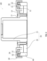
- FIG. 3 illustrates an example cross-sectional view of an axial force sensor 100 showing a signal pair 20.
- Each signal pair 20 may include a signal emitter 21 and a signal receiver 22.
- the signal emitter 21 and the signal receiver 22 may be connected to different parts of the sensing diaphragm 10. That is, in some examples, if the signal emitter 21 is coupled to the inner ring 11 of the sensing diaphragm 10, the signal receiver 22 may be coupled to the outer ring 12 of the sensing diaphragm 10. In other examples, if the signal emitter 21 is coupled to the outer ring 12 of the sensing diaphragm 10, the signal receiver 22 may be coupled to the inner ring 11 of the sensing diaphragm 10. When an axial load is applied to the outer ring 12 (or the inner ring 11) of the sensing diaphragm 10, the outer ring 12 deflects from the inner ring 11, which changes the readings of the signal receiver 22.
- the axial force sensor 100 may include only two signal pairs 20.
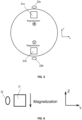
- the two signal pairs 20 may be oppositely arranged along a circumferential direction of the sensing diaphragm 10.
- the two signal pairs 20 may have opposite trends of signal changes, and thus the total force can be derived by subtracting one from the other and then being divided by two (e.g., calculating a differential output).
- an off-axis load for example, a bending moment
- the two signal pairs 20 may share the same trend of signal changes, and thus by subtracting one from the other, the deflection caused by this load may be canceled.
- signal changes caused by temperature shifts make the two signal pairs change in the same trend, and thus by subtracting one from the other, the temperature shifts can also be suppressed.
- Most non-resistive sensing methods are not sensitive to temperature changes, and thus even without perfect cancellation, temperature changes have little effect on the sensor.
- more pairs (e.g., 3, 4, or more) of signal emitters 21 and receivers 22 can also be utilized.
- the use of multiple pairs of signal emitters 21 and signal receivers 22 may enable the axial force sensor 100 to measure the axial force acting thereon more precisely by enabling more precise off-axis load cancellation and temperature compensation.
- the signal emitter 21 may be a magnet and the signal receiver 22 may correspondingly be a hall effect sensor.
- a hall effect sensor may work as follows.
- a hall effect sensor detects the magnetic field strength perpendicular to the magnetization axis (i.e. the Y axis in FIG. 5 ) and is capable of moving along the magnetization axis of a magnet (i.e. the Z axis out of and into the page in FIG. 5 )
- the relationship between the displacement of the sensor and the magnetic field strength detected by the sensor is substantially linear.
- the relationship between the detected magnetic field strength and the displacement of the sensor is less linear and can be modeled with non-linear functions, e.g., polynomial functions.
- a hall effect sensor detects the magnetic field strength perpendicular to the magnetization axis (i.e. the Y axis in FIG. 5 ) and is capable of moving in a secondary perpendicular direction to the magnetization axis of a magnet (i.e. the X axis in FIG. 5 ), the detected magnetic field strength does not change.
- the signal emitter 21 is a magnet
- the signal receiver 22 is a hall effect sensor
- the relationship between this displacement and the axial force acting on the axial force sensor 100 may be acquired (e.g., by modeling the axial force sensor 100 or by testing the prototype of the axial force sensor 100). Therefore, the axial force acting on the axial force sensor 100 may be obtained based on the readings of the signal receivers 22 of the signal pairs 20.
- the magnetization direction of the magnet 21a may be opposite to the magnetization direction of the magnet 21b (i.e., signal emitter 21b).
- the magnetization directions of the magnets 21a and 21b may both be substantially perpendicular to the extending direction of the sensing diaphragm 10. That is, the magnetization directions of the magnets 21a and 21b may be parallel to the axial direction of the axial force sensor 100.
- the hall effect sensors 22a and 22b may be spaced from the corresponding magnets 21a and 21b in the radial direction of the sensing diaphragm 10. In this way, when axial force is applied on the axial force sensor 100, the hall effect sensors 22a and 22b may move in the axial direction of the axial force sensor 100 with respect to the magnets 21a and 21b.
- the relationship between the displacement of the hall effect sensors 22a and 22b and the detected magnetic field strength may be substantially linear, which may facilitate the modeling of the structure and the calculation of the axial force.
- the two signal pairs 20 may be arranged to have the same trend of signal changes when the axial load is applied on the axial force sensor 100. In this situation, the above-described subtraction method may no longer be applicable, and the outputs of the two signal pairs 20 may be processed differently, for example, by applying a polynomial fit.
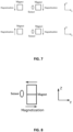
- FIGS. 7-9 show several possible configurations of each of the signal pairs 20 of the axial force sensor 100, where the Z direction represents the axial direction of the axial force sensor 100 and the Y direction represents the radial direction of the axial force sensor 100.
- the relationship between the axial displacement of the hall effect sensor (i.e., the signal receiver 22) with respect to the corresponding magnet (i.e., the signal emitter 21) and the detected magnetic field strength may not be linear. However, as long as the relative axial displacement of the hall effect sensor may significantly influence the value of the detected magnetic field strength, it can be utilized to calculate the axial force applied on the axial force sensor 100.
- the holding structure 30 of the axial force sensor 100 may include a center shaft 31 and a supporting plate 32.
- the holding structure 30 may be made from rigid material in some aspects.
- the holding structure 30 may be made from the same material as the sensing diaphragm 10.
- the inner ring 11 of the sensing diaphragm 10 may define a center hole 14.
- the center shaft 31 may pass through the center hole 14 and, in some examples, may be coupled to the inner ring 11.
- the supporting plate 32 may be connected to the center shaft 31 and may extend substantially parallel to the sensing diaphragm 10.
- the holding structure 30 and the sensing diaphragm 10 may be separate components. In other aspects, the holding structure 30 and the sensing diaphragm may be manufactured as one single component. In some examples, the holding structure 30 may provide more space for installing the components of the axial force sensor 100, and may facilitate the connection between the axial force sensor 100 and other external components.
- the axial force sensor 100 may be utilized in a robot actuator, and the holding structure 30 may be connected to a driven end of a motor assembly or to an output end (e.g., output flange) of the actuator.
- the signal emitter 21 may be installed on the outer ring 12 while the signal receiver 22 is installed on the supporting plate 32 and aligned with the signal emitter 21 in either the axial direction or the radial direction of the sensing diaphragm 10.
- the signal receiver 22 since the holding structure 30 is coupled to the inner ring 11 of the sensing diaphragm 10, the signal receiver 22 is also coupled to the inner ring 11 indirectly.
- the signal receiver 22 may be installed on the outer ring 12 while the signal emitter 21 is installed on the supporting plate 32 and aligned with the signal receiver 22 in either the axial direction or the radial direction of the sensing diaphragm 10.
- the signal receiver 22 is coupled to the outer ring 12 while the signal emitter 21 is coupled to the inner ring 11.
- the axial force sensor 100 may further include a shielding structure 40.
- the shielding structure 40 may be installed on the supporting plate 32 and located corresponding to the signal pairs 20 in the circumferential direction of the sensing diaphragm 10.
- the shielding structure 40 may enclose the signal pairs 20 to protect the signal pairs 20 from signal disruption and/or interference.
- the structure and material of the shielding structure 40 may be based on the type of the signal pairs 20. For example, if magnetic signals are used in the signal pairs 20, the shielding structure 40 may be made from high magnetic permeability material such as supermalloy, super mumetal alloys, sanbold, permalloy, carbon steel, martensite steel, etc.
- the axial force sensor 100 may further include a hard stop 50.
- the hard stop 50 may be installed on the supporting plate 32 and may enclose the outer ring 12 of the sensing diaphragm 10.
- the hard stop 50 may have, for example, a C-shaped configuration. In other examples, the hard stop 50 may take any number of different suitable configurations. In some aspects, there may exist clearances (not shown) between the hard stop 50 and the outer ring 12 on both the upper and lowers sides, and the hard stop 50 may be utilized to prevent over deflection of the outer ring 12. When excessive deflection occurs with overload, the rigid hard stop 50 may prevent further deflection of the outer ring 12, thus protecting the sensing diaphragm 10 from yielding and fatigue.
- the axial force sensor 100 may have only one hard stop 50 as illustrated figures. In other examples, the axial force sensor 100 may have more than one hard stop 50.
- the robot gripper 700 may include a catching mechanism 701 and an axial force sensor 702.
- the axial force sensor 702 may be utilized to measure the force acting on the catching mechanism 701.
- the structure and function of the axial force sensor 702 may be similar to any axial force sensor of the embodiments described above (e.g., the example axial force sensor 100).
- the robot gripper 700 may further include a driving assembly 703 and a shell 704.
- the driving assembly 703 may be coupled to the axial force sensor 702 and configured to drive the catching mechanism 701.
- the catching mechanism 701 and the driving assembly 703 may be installed on the shell 704 in any suitable way.
- the present disclosure also provides for a robot with at least one axial force sensor.
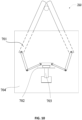
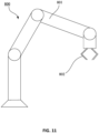
- the robot 800 may include multiple robotic arms 801 and an end effector 802.
- the end effector 802 may be a gripper, in which an axial force sensor (not shown) may be installed for measuring the gripping force of the gripper.
- the end effector 802 may be the robot gripper 700 that utilizes the axial force sensor 702 as described above.
- the end effector 802 may be any other suitable gripper that utilizes any suitable axial force sensor as described in the present disclosure.
- the robot 800 may include other force sensors (e.g., in the actuators) based on actual design requirements.
- the structure of the at least one axial force sensor may be similar to any axial force sensor of the embodiments described above.
Landscapes
- Engineering & Computer Science (AREA)
- Robotics (AREA)
- Mechanical Engineering (AREA)
- Chemical & Material Sciences (AREA)
- Analytical Chemistry (AREA)
- Physics & Mathematics (AREA)
- General Physics & Mathematics (AREA)
- Human Computer Interaction (AREA)
- Force Measurement Appropriate To Specific Purposes (AREA)
- Manipulator (AREA)
Claims (8)
- Capteur de force axiale (100), comprenantun diaphragme de détection (10) comprenant :une bague intérieure (11) ;une bague extérieure (12) ; etun élément de connexion (13) connecté entre la bague intérieure (11) et la bague extérieure (12), dans lequel l'élément de connexion (13) est plus souple dans une direction de la force axiale à détecter que dans d'autres directions de chargement ; etau moins deux paires de signaux (20) comprenant une première paire de signaux et une seconde paire de signaux disposées de manière opposée le long d'une direction circonférentielle du diaphragme de détection, chacune des au moins deux paires de signaux (20) comprenant :un émetteur de signal (21) couplé à l'une parmi la bague intérieure (11) et la bague extérieure (12), dans lequel l'émetteur de signal (21) est un aimant ; etun récepteur de signal (22) couplé à l'autre parmi la bague intérieure (11) et la bague extérieure (12), dans lequel le récepteur de signal (22) est un capteur à effet Hall, dans lequel :une direction de magnétisation de l'aimant de la première paire de signaux est opposée à une direction de magnétisation de l'aimant de la seconde paire de signaux ;la direction de magnétisation de l'aimant de la première paire de signaux et la direction de magnétisation de l'aimant de la seconde paire de signaux sont toutes deux perpendiculaires à une direction d'extension du diaphragme de détection (10) ; etle capteur à effet Hall de chacune de la première paire de signaux et de la seconde paire de signaux est espacé de l'aimant correspondant dans une direction radiale du diaphragme de détection (10).
- Capteur de force axiale (100) selon la revendication 1, comprenant en outre une structure de maintien (30), dans lequel la bague intérieure (11) définit un trou central (14), la structure de maintien (30) comprend :un arbre central (31) passant à travers le trou central (14) et couplé à la bague intérieure (11) ; etune plaque de support (32) connectée à l'arbre central (31) et s'étendant parallèlement au diaphragme de détection (10) .
- Capteur de force axiale (100) selon la revendication 2, comprenant en outre :une structure de blindage (41) installée sur la plaque de support (32) et située en correspondance avec les au moins deux paires de signaux (20) dans une direction circonférentielle du diaphragme de détection (10),dans lequel la structure de blindage (41) entoure les au moins deux paires de signaux (20) pour protéger les au moins deux paires de signaux (20) contre une perturbation de signal.
- Capteur de force axiale (100) selon la revendication 2 ou 3, comprenant en outre
une butée dure (50) installée sur la plaque de support (32) et entourant la bague extérieure (12), dans lequel il existe des jeux entre la butée dure (50) et la bague extérieure (12) sur les deux côtés supérieur et inférieur, et la butée dure (32) est configurée pour empêcher une déviation excessive de la bague extérieure (12). - Capteur de force axiale (100) selon l'une quelconque des revendications 2 à 4, dans lequel
l'émetteur de signal (21) est installé sur la bague extérieure (12) tandis que le récepteur de signal (22) est installé sur la plaque de support (32) et aligné avec l'émetteur de signal (21) dans une direction axiale ou dans une direction radiale du diaphragme de détection (10). - Capteur de force axiale (100) selon l'une quelconque des revendications 2 à 4, dans lequel
le récepteur de signal (22) est installé sur la bague extérieure (12) tandis que l'émetteur de signal (21) est installé sur la plaque de support (32) et aligné avec le récepteur de signal (22) dans une direction axiale ou dans une direction radiale du diaphragme de détection (10). - Préhenseur de robot (700) comprenant un mécanisme de saisie (701) et un capteur de force axiale (702), le capteur de force axiale (702) étant configuré pour mesurer une force agissant sur le mécanisme de saisie (701), caractérisé en ce que le capteur de force axiale (702) est le capteur de force axiale selon l'une quelconque des revendications 1 à 6.
- Robot (800) doté d'au moins un capteur de force axiale, caractérisé en ce que chacun du au moins un capteur de force axiale est le capteur de force axiale selon l'une quelconque des revendications 1 à 6.
Applications Claiming Priority (2)
| Application Number | Priority Date | Filing Date | Title |
|---|---|---|---|
| US201862693034P | 2018-07-02 | 2018-07-02 | |
| PCT/US2019/040060 WO2020009959A1 (fr) | 2018-07-02 | 2019-07-01 | Capteur de force axiale, dispositif de préhension robotique et robot équipé de ceux-ci |
Publications (3)
| Publication Number | Publication Date |
|---|---|
| EP3797268A1 EP3797268A1 (fr) | 2021-03-31 |
| EP3797268A4 EP3797268A4 (fr) | 2021-10-06 |
| EP3797268B1 true EP3797268B1 (fr) | 2024-09-04 |
Family
ID=69007879
Family Applications (1)
| Application Number | Title | Priority Date | Filing Date |
|---|---|---|---|
| EP19829928.1A Active EP3797268B1 (fr) | 2018-07-02 | 2019-07-01 | Capteur de force axiale, dispositif de préhension robotique et robot équipé de ceux-ci |
Country Status (5)
| Country | Link |
|---|---|
| US (1) | US11345043B2 (fr) |
| EP (1) | EP3797268B1 (fr) |
| JP (1) | JP7106759B2 (fr) |
| CN (1) | CN111183337A (fr) |
| WO (1) | WO2020009959A1 (fr) |
Families Citing this family (7)
| Publication number | Priority date | Publication date | Assignee | Title |
|---|---|---|---|---|
| NO341376B1 (no) | 2016-03-02 | 2017-10-23 | Akvadesign As | Oppdriftssystem for en merd |
| US10933535B2 (en) * | 2018-08-22 | 2021-03-02 | Flexiv Ltd. | Robot and gripper with synthetic fibrillar adhesive |
| USD1035730S1 (en) * | 2020-03-31 | 2024-07-16 | Mytide Therapeutics, Inc. | Gripping device |
| JP2023527179A (ja) * | 2020-06-28 | 2023-06-27 | シャンハイ・フレクシブ・ロボティクス・テクノロジー・カンパニー・リミテッド | 軸力センサアセンブリ、ロボットグリッパー及びロボット |
| CN111595505B (zh) * | 2020-06-28 | 2022-07-08 | 上海非夕机器人科技有限公司 | 轴向力传感器组件、机器人夹爪及机器人 |
| CN114905483B (zh) * | 2021-01-29 | 2024-12-13 | 苏州艾利特机器人有限公司 | 一种关节力矩传感器及机器人关节 |
| US12042929B2 (en) * | 2021-06-17 | 2024-07-23 | Shanghai Flexiv Robotics Technology Co., Ltd. | Sensing assembly, force and torque sensor assembly, robot joint and robot |
Citations (2)
| Publication number | Priority date | Publication date | Assignee | Title |
|---|---|---|---|---|
| WO2006053244A2 (fr) * | 2004-11-12 | 2006-05-18 | Stoneridge Control Devices, Inc. | Ensemble capteur de couple |
| US20070273367A1 (en) * | 2004-03-10 | 2007-11-29 | Robert Bosch Gmbh | Joining Element |
Family Cites Families (20)
| Publication number | Priority date | Publication date | Assignee | Title |
|---|---|---|---|---|
| US3705530A (en) | 1970-12-14 | 1972-12-12 | Collins Radio Co | Force hub sensor for control wheel steering |
| JPS6474411A (en) * | 1987-09-16 | 1989-03-20 | Yamaha Corp | Position detector |
| EP0333872B1 (fr) | 1987-09-18 | 1995-08-23 | Wacoh Corporation | Pince du robot |
| GB9919065D0 (en) * | 1999-08-12 | 1999-10-13 | Fast Technology Gmbh | Transducer Element |
| DE10301059A1 (de) | 2003-01-14 | 2004-07-22 | 3Dconnexion Gmbh | Anordnung zum Erfassen von Bewegungen oder Positionen zweier Objekte relativ zueinander |
| US20040244504A1 (en) | 2003-06-04 | 2004-12-09 | Jing Yuan | Apparatus and method of belt dynamic tension measurement |
| CN102087153B (zh) * | 2010-11-04 | 2012-10-31 | 燕山大学 | 轮辐式容错型并联结构六维力传感器 |
| US8966996B2 (en) | 2011-07-27 | 2015-03-03 | Tri-Force Management Corporation | Force sensor |
| JP5735882B2 (ja) * | 2011-08-02 | 2015-06-17 | Ntn株式会社 | 磁気式荷重センサ |
| AU2013200469B2 (en) | 2012-02-07 | 2016-03-24 | Methode Electronics, Inc. | Magnetic torque sensor for transmission converter drive plate |
| CN102632508B (zh) | 2012-04-17 | 2015-04-29 | 浙江大学 | 一种适用于机器人关节的平面扭簧 |
| JP5877134B2 (ja) | 2012-07-11 | 2016-03-02 | Ntn株式会社 | 磁気式荷重センサおよび電動ブレーキ装置 |
| DE102012217390A1 (de) | 2012-09-26 | 2014-03-27 | Siemens Aktiengesellschaft | Wegaufnehmermodul und Kraftmessdose |
| WO2016096418A1 (fr) * | 2014-12-16 | 2016-06-23 | Aktiebolaget Skf | Système de détermination de charge pour un palier d'élément roulant |
| EP3136069B1 (fr) * | 2015-08-24 | 2019-10-09 | Magnes Ltd. | Capteur de force |
| DE102015218993B3 (de) * | 2015-10-01 | 2016-12-22 | Schaeffler Technologies AG & Co. KG | Lageranordnung mit einer Dehnungssensoreinrichtung |
| WO2018029790A1 (fr) * | 2016-08-09 | 2018-02-15 | 株式会社 トライフォース・マネジメント | Capteur de force |
| JP6214072B1 (ja) * | 2016-08-09 | 2017-10-18 | 株式会社トライフォース・マネジメント | 力覚センサ |
| JP6501746B2 (ja) * | 2016-10-07 | 2019-04-17 | キヤノン株式会社 | 変位測定装置、ロボット、ロボットアーム及び物品の製造方法 |
| US10302510B2 (en) * | 2017-01-30 | 2019-05-28 | Tecat Performance Systems, Llc | Wireless axial load cell and sensor assembly |
-
2019
- 2019-06-28 US US16/456,562 patent/US11345043B2/en active Active
- 2019-07-01 JP JP2021522926A patent/JP7106759B2/ja active Active
- 2019-07-01 WO PCT/US2019/040060 patent/WO2020009959A1/fr not_active Ceased
- 2019-07-01 EP EP19829928.1A patent/EP3797268B1/fr active Active
- 2019-07-01 CN CN201980004849.7A patent/CN111183337A/zh active Pending
Patent Citations (2)
| Publication number | Priority date | Publication date | Assignee | Title |
|---|---|---|---|---|
| US20070273367A1 (en) * | 2004-03-10 | 2007-11-29 | Robert Bosch Gmbh | Joining Element |
| WO2006053244A2 (fr) * | 2004-11-12 | 2006-05-18 | Stoneridge Control Devices, Inc. | Ensemble capteur de couple |
Also Published As
| Publication number | Publication date |
|---|---|
| WO2020009959A1 (fr) | 2020-01-09 |
| JP7106759B2 (ja) | 2022-07-26 |
| JP2021534425A (ja) | 2021-12-09 |
| US11345043B2 (en) | 2022-05-31 |
| EP3797268A4 (fr) | 2021-10-06 |
| EP3797268A1 (fr) | 2021-03-31 |
| CN111183337A (zh) | 2020-05-19 |
| US20200001472A1 (en) | 2020-01-02 |
Similar Documents
| Publication | Publication Date | Title |
|---|---|---|
| EP3797268B1 (fr) | Capteur de force axiale, dispositif de préhension robotique et robot équipé de ceux-ci | |
| EP3814076B1 (fr) | Capteur de force et de couple à axes multiples et robot pourvu dudit capteur | |
| CN110462357B (zh) | 具有适度柔性的高可靠性扭矩传感器 | |
| JP5875382B2 (ja) | 力覚センサ、ロボット装置、ロボットハンド及び検出装置 | |
| JP5606662B2 (ja) | トルクセンサ及びトルクセンサ付モータ | |
| WO2013018715A1 (fr) | Capteur de charge magnétique | |
| CN104215372A (zh) | 一种机械臂关节扭矩测量装置 | |
| US20140144252A1 (en) | Torque sensor | |
| JP7692863B2 (ja) | 力覚センサ | |
| CN111829714B (zh) | 多自由度力和力矩传感器及机器人 | |
| US11913849B2 (en) | Multi-degree of freedom force and torque sensor and robot | |
| Qi et al. | Design of a ring-type bearingless torque sensor with low crosstalk error | |
| US12042929B2 (en) | Sensing assembly, force and torque sensor assembly, robot joint and robot | |
| CN116929615B (zh) | 一种电磁式复合多轴扭矩传感器及扭矩测量方法 | |
| US20170160150A1 (en) | Flexure-based system for measuring torque on a shaft | |
| CN113358246A (zh) | 感测组件、力和扭矩传感器组件、机器人关节及机器人 | |
| KR20250061466A (ko) | 단차를 포함하는 힘/토크 센서 및 그 제조방법 | |
| CN121577919A (zh) | 一种用于加速度传感器的解耦放大机构 |
Legal Events
| Date | Code | Title | Description |
|---|---|---|---|
| STAA | Information on the status of an ep patent application or granted ep patent |
Free format text: STATUS: THE INTERNATIONAL PUBLICATION HAS BEEN MADE |
|
| PUAI | Public reference made under article 153(3) epc to a published international application that has entered the european phase |
Free format text: ORIGINAL CODE: 0009012 |
|
| STAA | Information on the status of an ep patent application or granted ep patent |
Free format text: STATUS: REQUEST FOR EXAMINATION WAS MADE |
|
| 17P | Request for examination filed |
Effective date: 20201224 |
|
| AK | Designated contracting states |
Kind code of ref document: A1 Designated state(s): AL AT BE BG CH CY CZ DE DK EE ES FI FR GB GR HR HU IE IS IT LI LT LU LV MC MK MT NL NO PL PT RO RS SE SI SK SM TR |
|
| AX | Request for extension of the european patent |
Extension state: BA ME |
|
| A4 | Supplementary search report drawn up and despatched |
Effective date: 20210907 |
|
| DAV | Request for validation of the european patent (deleted) | ||
| DAX | Request for extension of the european patent (deleted) | ||
| RIC1 | Information provided on ipc code assigned before grant |
Ipc: B25J 13/08 20060101ALI20210901BHEP Ipc: G01N 3/08 20060101ALI20210901BHEP Ipc: G01L 1/12 20060101ALI20210901BHEP Ipc: G01L 1/00 20060101ALI20210901BHEP Ipc: G01D 5/12 20060101AFI20210901BHEP |
|
| RAP3 | Party data changed (applicant data changed or rights of an application transferred) |
Owner name: FLEXIV ROBOTICS INC Owner name: FLEXIV LTD. |
|
| P01 | Opt-out of the competence of the unified patent court (upc) registered |
Effective date: 20240207 |
|
| GRAP | Despatch of communication of intention to grant a patent |
Free format text: ORIGINAL CODE: EPIDOSNIGR1 |
|
| STAA | Information on the status of an ep patent application or granted ep patent |
Free format text: STATUS: GRANT OF PATENT IS INTENDED |
|
| INTG | Intention to grant announced |
Effective date: 20240318 |
|
| GRAS | Grant fee paid |
Free format text: ORIGINAL CODE: EPIDOSNIGR3 |
|
| GRAA | (expected) grant |
Free format text: ORIGINAL CODE: 0009210 |
|
| STAA | Information on the status of an ep patent application or granted ep patent |
Free format text: STATUS: THE PATENT HAS BEEN GRANTED |
|
| RAP3 | Party data changed (applicant data changed or rights of an application transferred) |
Owner name: FLEXIV ROBOTICS INC. Owner name: FLEXIV LTD. |
|
| AK | Designated contracting states |
Kind code of ref document: B1 Designated state(s): AL AT BE BG CH CY CZ DE DK EE ES FI FR GB GR HR HU IE IS IT LI LT LU LV MC MK MT NL NO PL PT RO RS SE SI SK SM TR |
|
| REG | Reference to a national code |
Ref country code: GB Ref legal event code: FG4D |
|
| REG | Reference to a national code |
Ref country code: CH Ref legal event code: EP |
|
| REG | Reference to a national code |
Ref country code: IE Ref legal event code: FG4D |
|
| REG | Reference to a national code |
Ref country code: DE Ref legal event code: R096 Ref document number: 602019058411 Country of ref document: DE |
|
| REG | Reference to a national code |
Ref country code: LT Ref legal event code: MG9D |
|
| REG | Reference to a national code |
Ref country code: NL Ref legal event code: MP Effective date: 20240904 |
|
| PG25 | Lapsed in a contracting state [announced via postgrant information from national office to epo] |
Ref country code: NO Free format text: LAPSE BECAUSE OF FAILURE TO SUBMIT A TRANSLATION OF THE DESCRIPTION OR TO PAY THE FEE WITHIN THE PRESCRIBED TIME-LIMIT Effective date: 20241204 |
|
| PG25 | Lapsed in a contracting state [announced via postgrant information from national office to epo] |
Ref country code: PL Free format text: LAPSE BECAUSE OF FAILURE TO SUBMIT A TRANSLATION OF THE DESCRIPTION OR TO PAY THE FEE WITHIN THE PRESCRIBED TIME-LIMIT Effective date: 20240904 Ref country code: FI Free format text: LAPSE BECAUSE OF FAILURE TO SUBMIT A TRANSLATION OF THE DESCRIPTION OR TO PAY THE FEE WITHIN THE PRESCRIBED TIME-LIMIT Effective date: 20240904 Ref country code: GR Free format text: LAPSE BECAUSE OF FAILURE TO SUBMIT A TRANSLATION OF THE DESCRIPTION OR TO PAY THE FEE WITHIN THE PRESCRIBED TIME-LIMIT Effective date: 20241205 |
|
| PG25 | Lapsed in a contracting state [announced via postgrant information from national office to epo] |
Ref country code: BG Free format text: LAPSE BECAUSE OF FAILURE TO SUBMIT A TRANSLATION OF THE DESCRIPTION OR TO PAY THE FEE WITHIN THE PRESCRIBED TIME-LIMIT Effective date: 20240904 |
|
| PG25 | Lapsed in a contracting state [announced via postgrant information from national office to epo] |
Ref country code: LV Free format text: LAPSE BECAUSE OF FAILURE TO SUBMIT A TRANSLATION OF THE DESCRIPTION OR TO PAY THE FEE WITHIN THE PRESCRIBED TIME-LIMIT Effective date: 20240904 |
|
| PG25 | Lapsed in a contracting state [announced via postgrant information from national office to epo] |
Ref country code: HR Free format text: LAPSE BECAUSE OF FAILURE TO SUBMIT A TRANSLATION OF THE DESCRIPTION OR TO PAY THE FEE WITHIN THE PRESCRIBED TIME-LIMIT Effective date: 20240904 |
|
| PG25 | Lapsed in a contracting state [announced via postgrant information from national office to epo] |
Ref country code: ES Free format text: LAPSE BECAUSE OF FAILURE TO SUBMIT A TRANSLATION OF THE DESCRIPTION OR TO PAY THE FEE WITHIN THE PRESCRIBED TIME-LIMIT Effective date: 20240904 Ref country code: RS Free format text: LAPSE BECAUSE OF FAILURE TO SUBMIT A TRANSLATION OF THE DESCRIPTION OR TO PAY THE FEE WITHIN THE PRESCRIBED TIME-LIMIT Effective date: 20241204 |
|
| PG25 | Lapsed in a contracting state [announced via postgrant information from national office to epo] |
Ref country code: RS Free format text: LAPSE BECAUSE OF FAILURE TO SUBMIT A TRANSLATION OF THE DESCRIPTION OR TO PAY THE FEE WITHIN THE PRESCRIBED TIME-LIMIT Effective date: 20241204 Ref country code: PL Free format text: LAPSE BECAUSE OF FAILURE TO SUBMIT A TRANSLATION OF THE DESCRIPTION OR TO PAY THE FEE WITHIN THE PRESCRIBED TIME-LIMIT Effective date: 20240904 Ref country code: NO Free format text: LAPSE BECAUSE OF FAILURE TO SUBMIT A TRANSLATION OF THE DESCRIPTION OR TO PAY THE FEE WITHIN THE PRESCRIBED TIME-LIMIT Effective date: 20241204 Ref country code: LV Free format text: LAPSE BECAUSE OF FAILURE TO SUBMIT A TRANSLATION OF THE DESCRIPTION OR TO PAY THE FEE WITHIN THE PRESCRIBED TIME-LIMIT Effective date: 20240904 Ref country code: HR Free format text: LAPSE BECAUSE OF FAILURE TO SUBMIT A TRANSLATION OF THE DESCRIPTION OR TO PAY THE FEE WITHIN THE PRESCRIBED TIME-LIMIT Effective date: 20240904 Ref country code: GR Free format text: LAPSE BECAUSE OF FAILURE TO SUBMIT A TRANSLATION OF THE DESCRIPTION OR TO PAY THE FEE WITHIN THE PRESCRIBED TIME-LIMIT Effective date: 20241205 Ref country code: FI Free format text: LAPSE BECAUSE OF FAILURE TO SUBMIT A TRANSLATION OF THE DESCRIPTION OR TO PAY THE FEE WITHIN THE PRESCRIBED TIME-LIMIT Effective date: 20240904 Ref country code: ES Free format text: LAPSE BECAUSE OF FAILURE TO SUBMIT A TRANSLATION OF THE DESCRIPTION OR TO PAY THE FEE WITHIN THE PRESCRIBED TIME-LIMIT Effective date: 20240904 Ref country code: BG Free format text: LAPSE BECAUSE OF FAILURE TO SUBMIT A TRANSLATION OF THE DESCRIPTION OR TO PAY THE FEE WITHIN THE PRESCRIBED TIME-LIMIT Effective date: 20240904 |
|
| REG | Reference to a national code |
Ref country code: AT Ref legal event code: MK05 Ref document number: 1720807 Country of ref document: AT Kind code of ref document: T Effective date: 20240904 |
|
| PG25 | Lapsed in a contracting state [announced via postgrant information from national office to epo] |
Ref country code: NL Free format text: LAPSE BECAUSE OF FAILURE TO SUBMIT A TRANSLATION OF THE DESCRIPTION OR TO PAY THE FEE WITHIN THE PRESCRIBED TIME-LIMIT Effective date: 20240904 |
|
| PG25 | Lapsed in a contracting state [announced via postgrant information from national office to epo] |
Ref country code: IS Free format text: LAPSE BECAUSE OF FAILURE TO SUBMIT A TRANSLATION OF THE DESCRIPTION OR TO PAY THE FEE WITHIN THE PRESCRIBED TIME-LIMIT Effective date: 20250104 Ref country code: PT Free format text: LAPSE BECAUSE OF FAILURE TO SUBMIT A TRANSLATION OF THE DESCRIPTION OR TO PAY THE FEE WITHIN THE PRESCRIBED TIME-LIMIT Effective date: 20250106 |
|
| PG25 | Lapsed in a contracting state [announced via postgrant information from national office to epo] |
Ref country code: RO Free format text: LAPSE BECAUSE OF FAILURE TO SUBMIT A TRANSLATION OF THE DESCRIPTION OR TO PAY THE FEE WITHIN THE PRESCRIBED TIME-LIMIT Effective date: 20240904 Ref country code: SM Free format text: LAPSE BECAUSE OF FAILURE TO SUBMIT A TRANSLATION OF THE DESCRIPTION OR TO PAY THE FEE WITHIN THE PRESCRIBED TIME-LIMIT Effective date: 20240904 |
|
| PG25 | Lapsed in a contracting state [announced via postgrant information from national office to epo] |
Ref country code: EE Free format text: LAPSE BECAUSE OF FAILURE TO SUBMIT A TRANSLATION OF THE DESCRIPTION OR TO PAY THE FEE WITHIN THE PRESCRIBED TIME-LIMIT Effective date: 20240904 Ref country code: AT Free format text: LAPSE BECAUSE OF FAILURE TO SUBMIT A TRANSLATION OF THE DESCRIPTION OR TO PAY THE FEE WITHIN THE PRESCRIBED TIME-LIMIT Effective date: 20240904 |
|
| PG25 | Lapsed in a contracting state [announced via postgrant information from national office to epo] |
Ref country code: CZ Free format text: LAPSE BECAUSE OF FAILURE TO SUBMIT A TRANSLATION OF THE DESCRIPTION OR TO PAY THE FEE WITHIN THE PRESCRIBED TIME-LIMIT Effective date: 20240904 |
|
| PG25 | Lapsed in a contracting state [announced via postgrant information from national office to epo] |
Ref country code: IT Free format text: LAPSE BECAUSE OF FAILURE TO SUBMIT A TRANSLATION OF THE DESCRIPTION OR TO PAY THE FEE WITHIN THE PRESCRIBED TIME-LIMIT Effective date: 20240904 Ref country code: SK Free format text: LAPSE BECAUSE OF FAILURE TO SUBMIT A TRANSLATION OF THE DESCRIPTION OR TO PAY THE FEE WITHIN THE PRESCRIBED TIME-LIMIT Effective date: 20240904 |
|
| REG | Reference to a national code |
Ref country code: DE Ref legal event code: R097 Ref document number: 602019058411 Country of ref document: DE |
|
| PG25 | Lapsed in a contracting state [announced via postgrant information from national office to epo] |
Ref country code: DK Free format text: LAPSE BECAUSE OF FAILURE TO SUBMIT A TRANSLATION OF THE DESCRIPTION OR TO PAY THE FEE WITHIN THE PRESCRIBED TIME-LIMIT Effective date: 20240904 |
|
| PLBE | No opposition filed within time limit |
Free format text: ORIGINAL CODE: 0009261 |
|
| STAA | Information on the status of an ep patent application or granted ep patent |
Free format text: STATUS: NO OPPOSITION FILED WITHIN TIME LIMIT |
|
| 26N | No opposition filed |
Effective date: 20250605 |
|
| PGFP | Annual fee paid to national office [announced via postgrant information from national office to epo] |
Ref country code: LU Payment date: 20250721 Year of fee payment: 7 |
|
| PG25 | Lapsed in a contracting state [announced via postgrant information from national office to epo] |
Ref country code: SE Free format text: LAPSE BECAUSE OF FAILURE TO SUBMIT A TRANSLATION OF THE DESCRIPTION OR TO PAY THE FEE WITHIN THE PRESCRIBED TIME-LIMIT Effective date: 20240904 |
|
| PGFP | Annual fee paid to national office [announced via postgrant information from national office to epo] |
Ref country code: DE Payment date: 20250722 Year of fee payment: 7 |
|
| PGFP | Annual fee paid to national office [announced via postgrant information from national office to epo] |
Ref country code: GB Payment date: 20250722 Year of fee payment: 7 Ref country code: BE Payment date: 20250718 Year of fee payment: 7 |
|
| PGFP | Annual fee paid to national office [announced via postgrant information from national office to epo] |
Ref country code: FR Payment date: 20250725 Year of fee payment: 7 |
|
| PGFP | Annual fee paid to national office [announced via postgrant information from national office to epo] |
Ref country code: CH Payment date: 20250801 Year of fee payment: 7 |
|
| PGFP | Annual fee paid to national office [announced via postgrant information from national office to epo] |
Ref country code: IE Payment date: 20250723 Year of fee payment: 7 |