WO2013018715A1 - Capteur de charge magnétique - Google Patents
Capteur de charge magnétique Download PDFInfo
- Publication number
- WO2013018715A1 WO2013018715A1 PCT/JP2012/069192 JP2012069192W WO2013018715A1 WO 2013018715 A1 WO2013018715 A1 WO 2013018715A1 JP 2012069192 W JP2012069192 W JP 2012069192W WO 2013018715 A1 WO2013018715 A1 WO 2013018715A1
- Authority
- WO
- WIPO (PCT)
- Prior art keywords
- magnetic
- sensor
- flange member
- load
- support member
- Prior art date
- Legal status (The legal status is an assumption and is not a legal conclusion. Google has not performed a legal analysis and makes no representation as to the accuracy of the status listed.)
- Ceased
Links
Images





Classifications
-
- G—PHYSICS
- G01—MEASURING; TESTING
- G01L—MEASURING FORCE, STRESS, TORQUE, WORK, MECHANICAL POWER, MECHANICAL EFFICIENCY, OR FLUID PRESSURE
- G01L1/00—Measuring force or stress, in general
- G01L1/12—Measuring force or stress, in general by measuring variations in the magnetic properties of materials resulting from the application of stress
-
- G—PHYSICS
- G01—MEASURING; TESTING
- G01L—MEASURING FORCE, STRESS, TORQUE, WORK, MECHANICAL POWER, MECHANICAL EFFICIENCY, OR FLUID PRESSURE
- G01L1/00—Measuring force or stress, in general
- G01L1/12—Measuring force or stress, in general by measuring variations in the magnetic properties of materials resulting from the application of stress
- G01L1/122—Measuring force or stress, in general by measuring variations in the magnetic properties of materials resulting from the application of stress by using permanent magnets
-
- F—MECHANICAL ENGINEERING; LIGHTING; HEATING; WEAPONS; BLASTING
- F16—ENGINEERING ELEMENTS AND UNITS; GENERAL MEASURES FOR PRODUCING AND MAINTAINING EFFECTIVE FUNCTIONING OF MACHINES OR INSTALLATIONS; THERMAL INSULATION IN GENERAL
- F16D—COUPLINGS FOR TRANSMITTING ROTATION; CLUTCHES; BRAKES
- F16D66/00—Arrangements for monitoring working conditions, e.g. wear, temperature
- F16D2066/005—Force, torque, stress or strain
Definitions
- This invention relates to a magnetic load sensor.
- An electric brake device generally converts the rotation of an electric motor into axial movement of a friction pad, and presses the friction pad against a brake disk to generate a braking force.
- the electric brake device In order to control the braking force to a desired magnitude, the electric brake device often incorporates a load sensor in a portion that receives a reaction force of a load applied to the friction pad.
- a load sensor a sensor that detects a load with a minute displacement as much as possible is used in order to improve the response of the electric brake.
- Patent Document 1 As a load sensor for detecting a load with such a small displacement, for example, the one described in Patent Document 1 is known.
- the load sensor disclosed in Patent Literature 1 is electrically connected between a pair of opposed annular plate-shaped pressing plates, a quartz crystal piezoelectric element sandwiched between the pair of pressing plates, and the quartz piezoelectric element and the pressing plate on one side. It has an insulating plate for insulation and a lead wire for taking out a voltage generated by the quartz crystal piezoelectric element.
- this load sensor applies a load to the quartz piezoelectric element, there is a possibility that the quartz piezoelectric element may be cracked or chipped when an impact load or a load oblique to the axial direction is applied.
- the load also acts on the insulating plate that electrically insulates between the piezoelectric element and one pressing plate, high durability is required for the insulating plate, but durability is ensured with inexpensive insulating plates such as resin. It was difficult to do.
- the load sensor of Patent Document 2 includes a metal cylinder and a strain gauge attached to the outer diameter surface of the cylinder.
- the load sensor when an axial load is input, the metal cylinder is distorted according to the axial load. Therefore, the load can be measured by measuring the strain with a strain gauge. Can be detected.
- this load sensor measures not only the amount of deformation of the metal cylinder itself but also the local distortion of the metal cylinder, so it is easily affected by temperature changes in the cylinder and variations in temperature distribution. Prone to errors.
- the problem to be solved by the present invention is to provide a load sensor that is excellent in durability and hardly affected by temperature, as a load sensor that detects a load with a minute displacement.
- a flange member that is deflected when an axial load is input, a support member that supports the flange member, a magnetic target that generates a magnetic field, and a magnet that detects the magnetic field generated by the magnetic target.
- One of the magnetic target and the magnetic sensor is fixed to the flange member, and the other is fixed to the support member so that the magnetic target and the magnetic sensor are relatively displaced by deflection of the flange member.
- a magnetic load sensor that detects the magnitude of the load based on a magnetic field detected by the sensor.
- the flange member bends, the relative position of the magnetic target and the magnetic sensor changes, and the output signal of the magnetic sensor changes according to the change in the relative position. Therefore, the magnitude of the load can be detected based on the output signal of the magnetic sensor.
- the load acts on the flange member to deflect the flange member, but does not act on the magnetic sensor. Therefore, even if an impact load or a load oblique to the axial direction is applied, the sensor is unlikely to fail, and high durability can be ensured. Further, since the axial load is detected not from the local distortion of the member receiving the load but from the amount of deformation of the member, it is not easily affected by variations in temperature and variations in temperature distribution.
- the magnetic target a plurality of permanent magnets having a magnetization direction in a direction orthogonal to the relative displacement direction of the magnetic target and the magnetic sensor, and magnetic poles having opposite polarities in the relative displacement direction of the magnetic target and the magnetic sensor It is preferable to use one arranged in a line and arrange the magnetic sensor in the vicinity of the boundary between the adjacent magnetic poles.
- the output signal of the magnetic sensor changes sharply with respect to the relative displacement in the axial direction of the magnetic target and the magnetic sensor, while it does not change much with respect to the relative displacement in directions other than the axial direction. Indicates directionality. Therefore, the output signal of the magnetic sensor is hardly affected by external vibration, and the magnitude of the axial load can be detected with stable accuracy.
- the flange member and the support member are formed as a pair of opposed annular plates, the outer diameter side portion of the flange member is supported by the support member, and one member of the flange member and the support member is connected to the other member. It is preferable that a cylindrical portion having an outer diameter surface facing the inner diameter surface is provided, the magnetic target is fixed to one of the inner diameter surface and the outer diameter surface, and the magnetic sensor is fixed to the other. If it does in this way, the precision of the relative position of the radial direction of a magnetic target and a magnetic sensor can be ensured easily.
- an annular protrusion for supporting the support member can be provided on the inner diameter side portion of the surface of the support member opposite to the side facing the flange member.
- the flange member and the support member are formed as a pair of opposed annular plates, the inner diameter side portion of the flange member is supported by the support member, and one member of the flange member and the support member is connected to the other member. It is preferable that a cylindrical portion having an inner diameter surface facing the outer diameter surface of the member is provided, the magnetic target is fixed to one of the inner diameter surface and the outer diameter surface, and the magnetic sensor is fixed to the other. Even in this case, it is possible to easily ensure the accuracy of the relative positions of the magnetic target and the magnetic sensor in the radial direction.
- an annular protrusion for supporting the support member can be provided on the outer diameter side portion of the surface of the support member opposite to the side facing the flange member.
- the portion into which the axial load of the flange member is input can be a spherical surface having a center on the center axis of the flange member. In this way, even when a load oblique to the axial direction is input, the point of action of the load on the flange member is close to the center axis of the flange member, and the flange member bends evenly. Accuracy is stable.
- a plurality of sets of the magnetic target and the magnetic sensor can be arranged at equal intervals in the circumferential direction on the same circumference around the central axis of the flange member. This makes it possible to estimate the input angle of the load with reference to the axial direction based on the difference between the output signals of the respective load sensors when a load in an oblique direction with respect to the axial direction is input. It becomes.
- the magnetic sensor it is possible to use a magnetoresistive element or a magnetoimpedance element, but using a Hall IC is advantageous in terms of cost, and it is easy to ensure heat resistance. Further, when a neodymium magnet is used as the permanent magnet, a strong magnetic field can be generated in a small space.
- the flange member and the support member are made of a material having the same linear expansion coefficient. In this way, the flange member and the support member thermally expand at the same rate when the temperature rises, so that the relative displacement in the axial direction of the magnetic target and the magnetic sensor due to temperature change is less likely to occur, and the effect of temperature change is effective. Can be suppressed.
- the input load acts on the flange member to bend the flange member.
- the load since the load does not act on the magnetic sensor, the load is oblique to the impact load or the axial direction. High durability against Further, since the axial load is detected not from the local distortion of the member receiving the load but from the amount of deformation of the member, it is not easily affected by variations in temperature and variations in temperature distribution.
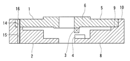
- Sectional drawing which shows the magnetic type load sensor of 1st Embodiment of this invention 1 is an enlarged sectional view of the magnetic load sensor shown in FIG.
- FIG. 2 is an enlarged sectional view showing an example in which the arrangement of the magnetic target and the magnetic sensor shown in FIG. 2 is changed.
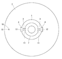
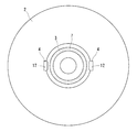
- the figure which shows an example of the relationship between the difference of the output signal of several magnetic sensors, and the input angle of a load The bottom view of the magnetic type load sensor which shows the other example of the magnetic target shown in FIG.
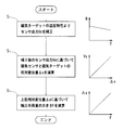
- Flow diagram showing an example of a method for estimating the magnitude of the axial load from the output signal of the magnetic sensor Sectional drawing which shows the example which used the key coupling instead of the positioning pin shown in FIG. 1 as a positioning means which fixes the relative position of the circumferential direction of a flange member and a supporting member.
- the magnetic load sensor includes an annular plate-shaped flange member 1 and a support member 2 that face each other in the axial direction, a magnetic target 3 that generates a magnetic field, and a magnetic sensor that detects the strength of the magnetic field generated by the magnetic target 3. 4.
- the flange member 1 has an annular plate portion 5 that is opposed to the support member 2 and an annular shape that is formed to protrude from the inner diameter side portion of the surface opposite to the side of the annular plate portion 5 that faces the support member 2. It consists of the load receiving part 6 and the cylindrical part 7 formed in the inner diameter side part of the surface on the side facing the support member 2 of the annular plate part 5.
- the support member 2 includes an annular plate portion 8 facing the flange member 1 and an annular support step portion formed to protrude from the outer diameter side portion of the surface of the annular plate portion 8 facing the flange member 1. 9 and a cylindrical fitting portion 10 formed on the outer diameter side of the support step portion 9.
- the support step portion 9 supports the outer diameter side portion of the flange member 1, and the interval between the annular plate portions 5 and 8 is maintained by the support step portion 9.
- the flange member 1 is fitted and fixed to the fitting portion 10 of the support member 2.
- a fixing method of the flange member 1 a method of inserting the flange member 1 into the fitting portion 10 with a tightening margin (press fitting), or an inner periphery of the fitting portion 10 by plastically deforming the outer peripheral edge of the flange member 1. It is possible to adopt a method (caulking) or the like that bites into the surface.
- a pin hole 14 penetrating in the axial direction is formed in the outer diameter side portion of the flange member 1, and an axial pin hole 15 is also formed in the support member 2, and positioning pins 16 are formed in both the pin holes 14, 15.
- the pin hole 14 of the flange member 1 and the pin hole 15 of the support member 2 have a circumferential position of the magnetic target 3 and a circumferential position of the magnetic sensor 4 when the positions of the pin holes 14 and 15 overlap each other.
- the relative position in the circumferential direction of the flange member 1 and the support member 2 is fixed by inserting the positioning pins 16 into the pin holes 14 and 15.
- the outer diameter surface of the cylindrical portion 7 faces the inner diameter surface of the support member 2 in the radial direction.
- the magnetic target 3 is attached to the chamfered portion 11 formed on the outer diameter surface of the cylindrical portion 7.
- the magnetic sensor 4 is fixed to a groove 12 that is fixed and formed on the inner diameter surface of the support member 2.
- Both the flange member 1 and the support member 2 are made of a metal material (iron, aluminum alloy, etc.), and the same material is used so that the linear expansion coefficients of both the members 1 and 2 are the same.
- the magnetic target 3 is composed of two permanent magnets 13 magnetized in the radial direction so as to have magnetic poles at the radially inner end and the radially outer end.
- the two permanent magnets 13 are arranged adjacent to each other so that magnetic poles having opposite polarities (that is, N pole and S pole) are aligned in the axial direction.
- the permanent magnet 13 for example, when a neodymium magnet is used, a strong magnetic field can be generated in a small space, but a samarium cobalt magnet, an alnico magnet, a ferrite magnet, or the like may be used. When a samarium cobalt magnet or an alnico magnet is used, it is possible to suppress a decrease in the magnetic field accompanying the temperature increase of the permanent magnet 13. Also, a praseodymium magnet or a samarium iron nitride magnet can be used.
- the magnetic sensor 4 is disposed in the vicinity of the boundary between adjacent magnetic poles of the two permanent magnets 13 so as to face the magnetic target 3 in the direction perpendicular to the axis (radial direction in the drawing).
- a magnetoresistive element sino-called MR sensor
- MI sensor magneto-impedance element
- the use of a Hall IC is advantageous in terms of cost and has high heat resistance. Easy to secure.
- the load acts on the flange member 1 to bend the flange member 1, but does not act on the magnetic sensor 4. Therefore, even if an impact load or a load oblique to the axial direction is applied, the magnetic sensor 4 is unlikely to fail, and high durability can be ensured.
- this magnetic load sensor detects the axial load from the deformation amount of the flange member 1 rather than the local distortion of the flange member 1, the magnetic load sensor is not easily affected by the temperature change of the flange member 1 and the variation in temperature distribution. It is possible to detect the magnitude of the axial load with high accuracy.
- the magnetic target 3 is fixed to the flange member 1 and the magnetic sensor 4 is fixed to the support member 2.
- the relationship between the magnetic target 3 and the magnetic sensor 4 may be reversed. That is, as shown in FIG. 4, the magnetic sensor 4 may be fixed to the outer diameter surface of the cylindrical portion 7 of the flange member 1, and the magnetic target 3 may be fixed to the inner diameter surface of the support member 2.
- a shear load mainly acts on the flange member 1
- a compressive load mainly acts on the support member 2.
- the magnetic target 3 is displaced by a shear load acting on the flange member 1, while the magnetic sensor 4 is hardly displaced by a compressive load acting on the support member 2, and the relative relationship between the magnetic target 3 and the magnetic sensor 4 is achieved.
- the axial load can be detected by the displacement.
- the amount of change in the relative position of the magnetic target 3 and the magnetic sensor 4 when an axial load is input to the flange member 1 is extremely small.
- the amount of change in the relative position of the magnetic target 3 and the magnetic sensor 4 is as extremely small as about 0.1 mm in the axial direction.
- a plurality of permanent magnets 13 are arranged such that opposite magnetic poles are aligned in the relative displacement direction of the magnetic target 3 and the magnetic sensor 4, and the magnetic sensor 4 is arranged in the vicinity of the boundary between the adjacent magnetic poles. Therefore, the output signal of the magnetic sensor 4 changes sharply with respect to the change in the relative position between the magnetic target 3 and the magnetic sensor 4, and the amount of change in the relative position between the magnetic target 3 and the magnetic sensor 4 is detected with high accuracy. Can do.
- the deflection of the flange member 1 can be detected with high accuracy due to insufficient sensor resolution. Can not do it. Therefore, instead of the flange member 1, it is conceivable to use a member having low rigidity (that is, a member such as a coil spring having a property of being greatly deformed when a load is applied).
- a member having low rigidity that is, a member such as a coil spring having a property of being greatly deformed when a load is applied.
- a member having low rigidity that is, a member such as a coil spring having a property of being greatly deformed when a load is applied.
- the magnetic load sensor is provided with a cylindrical portion 7 facing the inner diameter surface of the support member 2 on the flange member 1, and the magnetic target 3 is fixed to the outer diameter surface of the cylindrical portion 7. Since the magnetic sensor 4 is fixed to the magnetic sensor 4, the accuracy of the relative positions of the magnetic target 3 and the magnetic sensor 4 in the radial direction can be easily ensured.
- this magnetic type load sensor fixes the circumferential relative position of the flange member 1 and the supporting member 2 with the positioning pin 16, the accuracy of the circumferential relative position of the magnetic target 3 and the magnetic sensor 4 is secured. Is easy to secure.
- the flange member 1 and the support member 2 are formed of a material having the same linear expansion coefficient, the flange member 1 and the support member 2 have the same ratio when the temperature rises. Thermal expansion. For this reason, relative displacement in the axial direction between the magnetic target 3 and the magnetic sensor 4 due to temperature change is unlikely to occur, and the detection accuracy is stable.
- a capacitance sensor is used instead of the magnetic target 3 and the magnetic sensor 4, a complicated moisture-proof structure is required to cope with high temperature or low temperature conditions, resulting in high manufacturing costs. Further, in order to remove electrical noise, a complicated insulating structure, a sensor driving circuit, or a low-pass filter with a low cut-off frequency is required, which causes a problem of increasing costs. On the other hand, the magnetic load sensor does not require a complicated moisture-proof structure and does not require a complicated insulating structure for removing electrical noise.
- a seal structure for oils and fats is required, and the sensor installation conditions are limited.
- the magnetic load sensor does not require a seal structure for oils and fats.
- the output of the magnetic sensor 4 may be other analog output such as current in addition to voltage output, or may be digital output according to a predetermined protocol such as PWM duty ratio or serial / parallel communication.
- FIG. 5 shows a magnetic load sensor according to a second embodiment of the present invention.
- parts corresponding to those of the first embodiment are denoted by the same reference numerals, and description thereof is omitted.
- the flange member 1 and the support member 2 are accommodated in a cylindrical housing 20.
- a bottom plate 21 is provided at one end of the housing 20, and the bottom plate 21 supports a surface of the support member 2 opposite to the side facing the flange member 1.
- an axial preload is applied to the flange member 1 and the flange member 1 is prevented from coming off from the housing 20.
- the load can be stably detected even when the load is close to zero.
- FIG. 6 shows a magnetic load sensor according to a third embodiment of the present invention.
- the support member 2 includes an annular plate portion 8 facing the flange member 1 and an annular support step portion formed to protrude from the outer diameter side portion of the surface of the annular plate portion 8 facing the flange member 1. 9 and a cylindrical fitting portion 10 formed on the outer diameter side of the support step portion 9.
- a female screw 22 is formed on the inner periphery of the cylindrical fitting portion 10, and a male screw member 23 is screw-engaged with the female screw 22.
- the male screw member 23 is formed in a ring shape that penetrates the load receiving portion 6 of the flange member 1, and tightens the outer diameter side portion of the flange member 1 in the axial direction to apply an axial preload. As described above, when the axial preload is applied to the flange member 1, the load can be stably detected even when the load is close to zero.
- FIG. 7 shows a magnetic load sensor according to a fourth embodiment of the present invention.
- the flange member 1 and the support member 2 are accommodated in a cylindrical housing 24.
- a sliding bearing 25 impregnated with a lubricant is inserted into the housing 24, and the flange member 1 and the support member 2 are inserted into the sliding bearing 25 so as to be slidable in the axial direction.
- a bottom plate 26 is fixed to the lower end of the housing 24 by screwing.
- the bottom plate 26 supports a surface of the support member 2 opposite to the side facing the flange member 1.
- a lid plate 27 is fixed to the upper end of the housing 24 by screwing, and a preload spring 28 is incorporated between the lid plate 27 and the flange member 1 in an axially compressed state.
- the preload spring 28 fixes the position of the flange member 1 by pressing the outer diameter side portion of the flange member 1 toward the support step portion 9.
- a linear ball guide (not shown) having a guide ball may be used. Also in this embodiment, since the axial preload is applied to the flange member 1, the load can be stably detected in a state where the load is close to zero.
- FIG. 8 shows a magnetic load sensor according to a fifth embodiment of the present invention.
- the support member 2 has an annular protrusion 29 on the inner diameter side portion of the surface opposite to the side facing the flange member 1, and the support member 2 is supported by the annular protrusion 29.
- FIG. 9 shows a magnetic load sensor according to a sixth embodiment of the present invention.
- This magnetic load sensor has a configuration in which the inner diameter side and the outer diameter side of the magnetic load sensor of the fifth embodiment are reversed.
- the inner diameter side portion of the flange member 1 is supported by the support member 2.
- a cylindrical portion 7 having an inner diameter surface facing the outer diameter surface of the flange member 1 is formed on the outer diameter side portion of the support member 2.
- the magnetic target 3 is fixed to the outer diameter surface of the flange member 1, and the magnetic sensor 4 is fixed to the inner diameter surface of the cylindrical portion 7.
- the support member 2 has an annular protrusion 29 on the outer diameter side portion of the surface opposite to the side facing the flange member 1, and the support member 2 is supported by the annular protrusion 29. . Even in this case, when an axial load is input to the flange member 1, not only the flange member 1 but also the support member 2 is bent, and the magnetic target 3 and the magnetic sensor 4 are relatively moved by the deflection of both members. Since it is displaced, the resolution of load detection can be increased.
- FIG. 10 shows a magnetic load sensor according to a seventh embodiment of the present invention.
- a spherical surface 30 having a center on the central axis L of the flange member 1 is formed in the load receiving portion 6 of the flange member 1. In this way, even when a load oblique to the axial direction is input, the point of application of the load on the flange member 1 is close to the central axis L of the flange member 1, and the flange member 1 bends uniformly. The load detection accuracy is stable.
- the magnetic load sensor has a plurality of magnetic targets 3 and magnetic sensors 4 (two pairs in the figure), and the magnetic target 3 and the magnetic sensor 4 have the same circumference around the central axis L of the flange member 1. It is arranged on the top at equal intervals in the circumferential direction. In this way, as shown in FIG.
- the relationship between the difference (Vs1 ⁇ Vs2) between the output signals of the magnetic sensors 4 in each group and the input angle ⁇ f of the load F is obtained in advance, so that the axial direction
- the input angle ⁇ f of the load F with respect to the axial direction is estimated based on the difference (Vs1 ⁇ Vs2) between the output signals of the magnetic sensors 4. Is possible. It is also possible to obtain the magnitude of the axial component of the input load F based on the estimated input angle ⁇ f.
- the magnetic target 3 may be individually provided corresponding to each magnetic sensor 4, and as shown in FIG. A ring-shaped magnetic target 3 may be provided.
- the ring-shaped magnetic target 3 as shown in FIG. 14 it is not necessary to manage the relative positions of the flange member 1 and the support member 2 in the circumferential direction, and the assembly workability is improved.
- FIG. 15 shows a method of estimating the input axial load F from the output signal Vs of the magnetic sensor 4.
- the relationship between the magnetic field B generated by the permanent magnet 13 and the temperature T is grasped in advance, and the output signal Vs of the magnetic sensor 4 is corrected based on the relationship (step S1).
- the relative displacement ⁇ x between the magnetic sensor 4 and the magnetic target 3 is estimated based on the corrected sensor output Vs (step S2).
- the magnitude of the axial load F is calculated based on the relative displacement ⁇ x (step S3).
- a magnetic sensor 4 having a temperature compensation function such as a Hall IC may be used in advance, and the load may be estimated from the output of the magnetic sensor 4.
- the positioning pin 16 has been described as an example of the means for fixing the relative position in the circumferential direction of the flange member 1 and the support member 2, but instead of the positioning pin, as shown in FIGS.
- a key combination may be employed. 16 and 17, a key groove 17 extending in the axial direction is formed on the outer periphery of the flange member 1, and a key protrusion 18 extending in the axial direction is formed on the inner periphery of the fitting portion 10 of the support member 2.
- the protrusion 18 is fitted in the key groove 17.
- the key groove 17 and the key protrusion 18 are arranged so that the circumferential position of the magnetic target 3 and the circumferential position of the magnetic sensor 4 match when both are fitted.
- key grooves are respectively formed on the outer periphery of the flange member 1 and the inner periphery of the fitting portion 10 of the support member 2, and a common key member is fitted in both the key grooves. You may make it match.
- key coupling serration coupling, concave-convex coupling on axially opposed surfaces, and the like can also be employed.
- the magnetization direction of the magnetic target 3 is orthogonal to the relative displacement direction of the magnetic target 3 and the magnetic sensor 4 in order to detect the amount of change in the relative position between the magnetic target 3 and the magnetic sensor 4 with high accuracy.
- the magnetic target 3 is arranged so that the magnetization direction of the magnetic target 3 is parallel to the relative displacement direction of the magnetic target 3 and the magnetic sensor 4.
- the magnetic sensor 4 may be arranged in the vicinity.
Landscapes
- Physics & Mathematics (AREA)
- General Physics & Mathematics (AREA)
- Force Measurement Appropriate To Specific Purposes (AREA)
- Transmission And Conversion Of Sensor Element Output (AREA)
Abstract
L'invention concerne un capteur de charge qui détecte la charge par des déplacements minimes, qui présente une durabilité supérieure et qui n'est pas facilement affecté par la température. Le capteur de charge magnétique comprend : un élément de flasque (1) qui reçoit une charge dans le sens axial et se déforme ; un élément de support (2) pour supporter l'élément de flasque (1) ; une cible magnétique (3) pour générer un champ magnétique ; et un capteur magnétique (4) qui détecte le champ magnétique généré par la cible magnétique (3). Le capteur de charge magnétique possède une structure dans laquelle la cible magnétique (3) est fixée à l'élément de flasque (1) de telle manière que la cible magnétique (3) et le capteur magnétique (4) sont déplacés l'un par rapport à l'autre par la déformation de l'élément de flasque (1) ; le capteur magnétique (4) est fixé à l'élément de support (2) ; et la grandeur de la charge est détectée en fonction du champ magnétique détecté par le capteur magnétique (4).
Priority Applications (3)
| Application Number | Priority Date | Filing Date | Title |
|---|---|---|---|
| EP12819872.8A EP2741063B1 (fr) | 2011-08-02 | 2012-07-27 | Unité de capteur de charge magnétique |
| US14/235,818 US9482587B2 (en) | 2011-08-02 | 2012-07-27 | Magnetic load sensor unit |
| CN201280037827.9A CN103765178B (zh) | 2011-08-02 | 2012-07-27 | 磁式负载传感器 |
Applications Claiming Priority (2)
| Application Number | Priority Date | Filing Date | Title |
|---|---|---|---|
| JP2011169160A JP5735882B2 (ja) | 2011-08-02 | 2011-08-02 | 磁気式荷重センサ |
| JP2011-169160 | 2011-08-02 |
Publications (1)
| Publication Number | Publication Date |
|---|---|
| WO2013018715A1 true WO2013018715A1 (fr) | 2013-02-07 |
Family
ID=47629238
Family Applications (1)
| Application Number | Title | Priority Date | Filing Date |
|---|---|---|---|
| PCT/JP2012/069192 Ceased WO2013018715A1 (fr) | 2011-08-02 | 2012-07-27 | Capteur de charge magnétique |
Country Status (5)
| Country | Link |
|---|---|
| US (1) | US9482587B2 (fr) |
| EP (1) | EP2741063B1 (fr) |
| JP (1) | JP5735882B2 (fr) |
| CN (1) | CN103765178B (fr) |
| WO (1) | WO2013018715A1 (fr) |
Cited By (2)
| Publication number | Priority date | Publication date | Assignee | Title |
|---|---|---|---|---|
| JP2016156800A (ja) * | 2015-02-25 | 2016-09-01 | 日本精工株式会社 | 力覚センサ |
| JP2018059854A (ja) * | 2016-10-07 | 2018-04-12 | キヤノン株式会社 | 変位測定装置、ロボット、ロボットアーム及び物品の製造方法 |
Families Citing this family (28)
| Publication number | Priority date | Publication date | Assignee | Title |
|---|---|---|---|---|
| JP5877134B2 (ja) | 2012-07-11 | 2016-03-02 | Ntn株式会社 | 磁気式荷重センサおよび電動ブレーキ装置 |
| ITTO20130307A1 (it) | 2013-04-17 | 2014-10-18 | Itt Italia Srl | Metodo per realizzare un elemento frenante, in particolare una pastiglia freno, sensorizzato, pastiglia freno sensorizzata, impianto frenante di veicolo e metodo associato |
| JP6505399B2 (ja) * | 2014-09-02 | 2019-04-24 | Ntn株式会社 | 車両ブレーキ装置用荷重センサ、電動式直動アクチュエータおよび電動ブレーキ装置 |
| CN105987497B (zh) * | 2015-01-28 | 2019-08-27 | 广东美的生活电器制造有限公司 | 无绳液体加热装置 |
| US9939035B2 (en) | 2015-05-28 | 2018-04-10 | Itt Italia S.R.L. | Smart braking devices, systems, and methods |
| ITUB20151291A1 (it) * | 2015-05-28 | 2016-11-28 | Itt Italia Srl | Dispositivo frenante per veicoli |
| JP6133360B2 (ja) | 2015-06-01 | 2017-05-24 | Ntn株式会社 | 電動ブレーキ装置 |
| CN105136346B (zh) * | 2015-07-31 | 2018-11-06 | 北京博源天衡科技有限公司 | 一种新型负荷传感器 |
| EP3136069B1 (fr) * | 2015-08-24 | 2019-10-09 | Magnes Ltd. | Capteur de force |
| ITUB20153706A1 (it) | 2015-09-17 | 2017-03-17 | Itt Italia Srl | Dispositivo frenante per veicolo pesante e metodo di prevenzione del surriscaldamento dei freni in un veicolo pesante |
| ITUB20153709A1 (it) | 2015-09-17 | 2017-03-17 | Itt Italia Srl | Dispositivo di analisi e gestione dei dati generati da un sistema frenante sensorizzato per veicoli |
| ITUA20161336A1 (it) | 2016-03-03 | 2017-09-03 | Itt Italia Srl | Dispositivo e metodo per il miglioramento delle prestazioni di un sistema antibloccaggio e antiscivolamento di un veicolo |
| US11040682B1 (en) * | 2016-03-21 | 2021-06-22 | Paradigm Research and Engineering, LLC | Blast detection and safety deployment system and method for using the same |
| IT201600077944A1 (it) | 2016-07-25 | 2018-01-25 | Itt Italia Srl | Dispositivo per il rilevamento della coppia residua di frenatura in un veicolo equipaggiato con freni a disco |
| JP6527491B2 (ja) * | 2016-07-26 | 2019-06-05 | 住友理工株式会社 | 弾性連結装置 |
| CN108362574A (zh) * | 2018-04-28 | 2018-08-03 | 四川大学 | 高温高压多场耦合下岩石力学测试承载系统 |
| US11345043B2 (en) * | 2018-07-02 | 2022-05-31 | Flexiv Ltd. | Axial force sensor, robot gripper, and robot having the same |
| CN109443623B (zh) * | 2018-11-09 | 2020-05-26 | 吉林大学 | 南极冰钻用绞车绕缆拉力传感装置 |
| US11879792B2 (en) * | 2019-02-18 | 2024-01-23 | Xela Robotics Co., Ltd. | Magnetic sensing system, detection device, and magnetic interference offset method |
| US10928227B2 (en) * | 2019-04-15 | 2021-02-23 | Caterpillar Inc. | Mounting system for mounting a sensor assembly |
| CN110174192B (zh) * | 2019-04-26 | 2024-08-20 | 中船双瑞(洛阳)特种装备股份有限公司 | 一种竖向测力装置以及测力方法 |
| IT201900015839A1 (it) | 2019-09-06 | 2021-03-06 | Itt Italia Srl | Pastiglia freno per veicoli e suo processo di produzione |
| JP7276063B2 (ja) * | 2019-10-10 | 2023-05-18 | 日本精工株式会社 | センサユニット |
| EP3875913B1 (fr) * | 2020-03-04 | 2023-10-25 | Melexis Technologies SA | Capteur hybride de position |
| IT202000013408A1 (it) | 2020-06-05 | 2021-12-05 | Itt Italia Srl | Pastiglia freno intelligente di veicolo e suo metodo di manifattura |
| US20220065609A1 (en) * | 2020-08-25 | 2022-03-03 | Alexandre N. Terentiev | Integrated spacing sensor for joined parts and related methods |
| US11047670B1 (en) * | 2020-08-25 | 2021-06-29 | Alexandre N. Terentiev | Integrated spacing sensor for joined parts and related methods |
| WO2022248114A1 (fr) | 2021-05-25 | 2022-12-01 | Itt Italia S.R.L. | Procédé et dispositif d'estimation de couple résiduel entre des éléments freinés et de freinage d'un véhicule |
Citations (7)
| Publication number | Priority date | Publication date | Assignee | Title |
|---|---|---|---|---|
| JPS58201041A (ja) * | 1982-05-19 | 1983-11-22 | Mitsubishi Electric Corp | テ−プ張力検出装置 |
| JPS60177232A (ja) * | 1984-02-24 | 1985-09-11 | Nippon Telegr & Teleph Corp <Ntt> | 多分力検出器 |
| JPS6238328A (ja) * | 1985-08-13 | 1987-02-19 | Agency Of Ind Science & Technol | 広測定範囲形ロ−ドセル |
| JPH11132874A (ja) * | 1997-08-28 | 1999-05-21 | Kawatetsu Advantech Kk | ロードセル及びロードセルを備える荷重検出装置 |
| JP2005221418A (ja) * | 2004-02-06 | 2005-08-18 | Tdk Corp | 圧力センサ |
| JP2010210461A (ja) * | 2009-03-11 | 2010-09-24 | Seiko Epson Corp | 力覚センサー |
| JP2011112511A (ja) * | 2009-11-26 | 2011-06-09 | Canon Inc | 磁気式力覚センサ |
Family Cites Families (12)
| Publication number | Priority date | Publication date | Assignee | Title |
|---|---|---|---|---|
| JPH07318441A (ja) | 1994-05-24 | 1995-12-08 | Matsushita Electric Ind Co Ltd | 計測器用歪センサおよびこれを用いたロードセル式計測器 |
| CN2241875Y (zh) * | 1995-11-20 | 1996-12-04 | 上海铁道大学 | 霍尔型土壤压力传感器 |
| US6123183A (en) * | 1997-11-26 | 2000-09-26 | Ntn Corporation | Rotation transmission device |
| DE10314449A1 (de) * | 2003-03-31 | 2004-10-14 | Robert Bosch Gmbh | Sensoranordnung zur Kraftmessung |
| DE102005013142A1 (de) * | 2005-03-22 | 2006-09-28 | Robert Bosch Gmbh | Bremskraftmessvorrichtung für eine Reibungsbremse |
| JP4788351B2 (ja) * | 2006-01-19 | 2011-10-05 | 株式会社ジェイテクト | 燃料電池用過給機 |
| US8096173B2 (en) * | 2007-04-25 | 2012-01-17 | Toyota Jidosha Kabushiki Kaisha | Tire action force detecting device |
| JP2009229453A (ja) * | 2008-02-28 | 2009-10-08 | Seiko Epson Corp | 圧力検出装置及び圧力検出方法 |
| DE102008011881A1 (de) * | 2008-02-29 | 2009-09-10 | Tecpharma Licensing Ag | Leerschießgeschwindigkeitsbegrenzungsbremse |
| DE102008042298A1 (de) * | 2008-09-23 | 2010-03-25 | Robert Bosch Gmbh | Bremssattel für eine Scheibenbremse |
| JP2011080586A (ja) | 2009-09-10 | 2011-04-21 | Akebono Brake Ind Co Ltd | 電動式ディスクブレーキ |
| JP5778513B2 (ja) | 2011-07-28 | 2015-09-16 | Ntn株式会社 | 直動アクチュエータ用の磁気式荷重センサおよび直動アクチュエータ |
-
2011
- 2011-08-02 JP JP2011169160A patent/JP5735882B2/ja active Active
-
2012
- 2012-07-27 WO PCT/JP2012/069192 patent/WO2013018715A1/fr not_active Ceased
- 2012-07-27 US US14/235,818 patent/US9482587B2/en active Active
- 2012-07-27 CN CN201280037827.9A patent/CN103765178B/zh active Active
- 2012-07-27 EP EP12819872.8A patent/EP2741063B1/fr active Active
Patent Citations (7)
| Publication number | Priority date | Publication date | Assignee | Title |
|---|---|---|---|---|
| JPS58201041A (ja) * | 1982-05-19 | 1983-11-22 | Mitsubishi Electric Corp | テ−プ張力検出装置 |
| JPS60177232A (ja) * | 1984-02-24 | 1985-09-11 | Nippon Telegr & Teleph Corp <Ntt> | 多分力検出器 |
| JPS6238328A (ja) * | 1985-08-13 | 1987-02-19 | Agency Of Ind Science & Technol | 広測定範囲形ロ−ドセル |
| JPH11132874A (ja) * | 1997-08-28 | 1999-05-21 | Kawatetsu Advantech Kk | ロードセル及びロードセルを備える荷重検出装置 |
| JP2005221418A (ja) * | 2004-02-06 | 2005-08-18 | Tdk Corp | 圧力センサ |
| JP2010210461A (ja) * | 2009-03-11 | 2010-09-24 | Seiko Epson Corp | 力覚センサー |
| JP2011112511A (ja) * | 2009-11-26 | 2011-06-09 | Canon Inc | 磁気式力覚センサ |
Non-Patent Citations (1)
| Title |
|---|
| See also references of EP2741063A4 * |
Cited By (5)
| Publication number | Priority date | Publication date | Assignee | Title |
|---|---|---|---|---|
| JP2016156800A (ja) * | 2015-02-25 | 2016-09-01 | 日本精工株式会社 | 力覚センサ |
| JP2018059854A (ja) * | 2016-10-07 | 2018-04-12 | キヤノン株式会社 | 変位測定装置、ロボット、ロボットアーム及び物品の製造方法 |
| CN107914265A (zh) * | 2016-10-07 | 2018-04-17 | 佳能株式会社 | 位移测量设备、机器人及机器人臂 |
| US10583570B2 (en) | 2016-10-07 | 2020-03-10 | Canon Kabushiki Kaisha | Displacement measurement device, robot, and robot arm |
| CN107914265B (zh) * | 2016-10-07 | 2021-08-10 | 佳能株式会社 | 位移测量设备、机器人及机器人臂 |
Also Published As
| Publication number | Publication date |
|---|---|
| US20140224038A1 (en) | 2014-08-14 |
| JP5735882B2 (ja) | 2015-06-17 |
| EP2741063B1 (fr) | 2019-05-08 |
| CN103765178B (zh) | 2016-08-03 |
| US9482587B2 (en) | 2016-11-01 |
| EP2741063A4 (fr) | 2014-12-24 |
| CN103765178A (zh) | 2014-04-30 |
| JP2013032970A (ja) | 2013-02-14 |
| EP2741063A1 (fr) | 2014-06-11 |
Similar Documents
| Publication | Publication Date | Title |
|---|---|---|
| JP5735882B2 (ja) | 磁気式荷重センサ | |
| US9846090B2 (en) | Magnetic load sensor for use in a linear motion actuator, and a linear motion actuator | |
| US8237432B2 (en) | Rotation angle sensor | |
| CN104428646B (zh) | 磁式负载传感器以及电动制动装置 | |
| EP3797268B1 (fr) | Capteur de force axiale, dispositif de préhension robotique et robot équipé de ceux-ci | |
| CN101120177B (zh) | 带有旋转检测装置的轴承 | |
| US10508897B2 (en) | Magnet device and position sensing system | |
| JP5131537B2 (ja) | 角度検出装置 | |
| EP3618230A1 (fr) | Dispositif de détection | |
| US20110080163A1 (en) | Rotational angle sensing device | |
| JP4679358B2 (ja) | 回転角度検出装置 | |
| CN111693194B (zh) | 力测量设备、传动装置、执行装置和力测量设备的应用 | |
| US10396611B2 (en) | Rotor of rotary machine | |
| US11624669B2 (en) | Pressure sensor for high pressures | |
| US7219552B2 (en) | Scalable high sensitivity magnetostrictive pressure sensor | |
| JP5865184B2 (ja) | 磁気式荷重センサおよび電動ブレーキ装置 | |
| JP2012088185A (ja) | 磁気検知デバイス及び磁歪力センサ | |
| JP2016019362A (ja) | ブラシレスモータ | |
| JP5440946B2 (ja) | 磁歪力センサ | |
| JP2010286266A (ja) | エンコーダ | |
| TW201702565A (zh) | 具有轉矩測量構件的用於小型和微型驅動裝置的傳動裝置 | |
| JP7768447B2 (ja) | 磁歪式トルクセンサ | |
| JP4905215B2 (ja) | 磁歪式軸力センサ | |
| US9903507B2 (en) | Micro-position gap sensor assembly | |
| JP6169676B2 (ja) | 磁気式荷重センサおよび電動ブレーキ装置 |
Legal Events
| Date | Code | Title | Description |
|---|---|---|---|
| 121 | Ep: the epo has been informed by wipo that ep was designated in this application |
Ref document number: 12819872 Country of ref document: EP Kind code of ref document: A1 |
|
| WWE | Wipo information: entry into national phase |
Ref document number: 14235818 Country of ref document: US |
|
| NENP | Non-entry into the national phase |
Ref country code: DE |
|
| WWE | Wipo information: entry into national phase |
Ref document number: 2012819872 Country of ref document: EP |