EP3797441B1 - Metallorganische perowskit-solarzelle, tandem-solarzelle sowie herstellungsverfahren dazu - Google Patents
Metallorganische perowskit-solarzelle, tandem-solarzelle sowie herstellungsverfahren dazu Download PDFInfo
- Publication number
- EP3797441B1 EP3797441B1 EP19745981.1A EP19745981A EP3797441B1 EP 3797441 B1 EP3797441 B1 EP 3797441B1 EP 19745981 A EP19745981 A EP 19745981A EP 3797441 B1 EP3797441 B1 EP 3797441B1
- Authority
- EP
- European Patent Office
- Prior art keywords
- solar cell
- layer
- metal
- organic
- cell according
- Prior art date
- Legal status (The legal status is an assumption and is not a legal conclusion. Google has not performed a legal analysis and makes no representation as to the accuracy of the status listed.)
- Active
Links
Images


Classifications
-
- H—ELECTRICITY
- H10—SEMICONDUCTOR DEVICES; ELECTRIC SOLID-STATE DEVICES NOT OTHERWISE PROVIDED FOR
- H10K—ORGANIC ELECTRIC SOLID-STATE DEVICES
- H10K30/00—Organic devices sensitive to infrared radiation, light, electromagnetic radiation of shorter wavelength or corpuscular radiation
- H10K30/10—Organic devices sensitive to infrared radiation, light, electromagnetic radiation of shorter wavelength or corpuscular radiation comprising heterojunctions between organic semiconductors and inorganic semiconductors
- H10K30/15—Sensitised wide-bandgap semiconductor devices, e.g. dye-sensitised TiO2
- H10K30/151—Sensitised wide-bandgap semiconductor devices, e.g. dye-sensitised TiO2 the wide bandgap semiconductor comprising titanium oxide, e.g. TiO2
-
- H—ELECTRICITY
- H01—ELECTRIC ELEMENTS
- H01G—CAPACITORS; CAPACITORS, RECTIFIERS, DETECTORS, SWITCHING DEVICES, LIGHT-SENSITIVE OR TEMPERATURE-SENSITIVE DEVICES OF THE ELECTROLYTIC TYPE
- H01G9/00—Electrolytic capacitors, rectifiers, detectors, switching devices, light-sensitive or temperature-sensitive devices; Processes of their manufacture
- H01G9/0029—Processes of manufacture
- H01G9/0036—Formation of the solid electrolyte layer
-
- H—ELECTRICITY
- H01—ELECTRIC ELEMENTS
- H01G—CAPACITORS; CAPACITORS, RECTIFIERS, DETECTORS, SWITCHING DEVICES, LIGHT-SENSITIVE OR TEMPERATURE-SENSITIVE DEVICES OF THE ELECTROLYTIC TYPE
- H01G9/00—Electrolytic capacitors, rectifiers, detectors, switching devices, light-sensitive or temperature-sensitive devices; Processes of their manufacture
- H01G9/20—Light-sensitive devices
- H01G9/2004—Light-sensitive devices characterised by the electrolyte, e.g. comprising an organic electrolyte
- H01G9/2009—Solid electrolytes
-
- H—ELECTRICITY
- H01—ELECTRIC ELEMENTS
- H01G—CAPACITORS; CAPACITORS, RECTIFIERS, DETECTORS, SWITCHING DEVICES, LIGHT-SENSITIVE OR TEMPERATURE-SENSITIVE DEVICES OF THE ELECTROLYTIC TYPE
- H01G9/00—Electrolytic capacitors, rectifiers, detectors, switching devices, light-sensitive or temperature-sensitive devices; Processes of their manufacture
- H01G9/20—Light-sensitive devices
- H01G9/2068—Panels or arrays of photoelectrochemical cells, e.g. photovoltaic modules based on photoelectrochemical cells
- H01G9/2072—Panels or arrays of photoelectrochemical cells, e.g. photovoltaic modules based on photoelectrochemical cells comprising two or more photoelectrodes sensible to different parts of the solar spectrum, e.g. tandem cells
-
- H—ELECTRICITY
- H01—ELECTRIC ELEMENTS
- H01G—CAPACITORS; CAPACITORS, RECTIFIERS, DETECTORS, SWITCHING DEVICES, LIGHT-SENSITIVE OR TEMPERATURE-SENSITIVE DEVICES OF THE ELECTROLYTIC TYPE
- H01G9/00—Electrolytic capacitors, rectifiers, detectors, switching devices, light-sensitive or temperature-sensitive devices; Processes of their manufacture
- H01G9/20—Light-sensitive devices
- H01G9/2068—Panels or arrays of photoelectrochemical cells, e.g. photovoltaic modules based on photoelectrochemical cells
- H01G9/2077—Sealing arrangements, e.g. to prevent the leakage of the electrolyte
-
- H—ELECTRICITY
- H10—SEMICONDUCTOR DEVICES; ELECTRIC SOLID-STATE DEVICES NOT OTHERWISE PROVIDED FOR
- H10K—ORGANIC ELECTRIC SOLID-STATE DEVICES
- H10K30/00—Organic devices sensitive to infrared radiation, light, electromagnetic radiation of shorter wavelength or corpuscular radiation
- H10K30/30—Organic devices sensitive to infrared radiation, light, electromagnetic radiation of shorter wavelength or corpuscular radiation comprising bulk heterojunctions, e.g. interpenetrating networks of donor and acceptor material domains
-
- H—ELECTRICITY
- H10—SEMICONDUCTOR DEVICES; ELECTRIC SOLID-STATE DEVICES NOT OTHERWISE PROVIDED FOR
- H10K—ORGANIC ELECTRIC SOLID-STATE DEVICES
- H10K30/00—Organic devices sensitive to infrared radiation, light, electromagnetic radiation of shorter wavelength or corpuscular radiation
- H10K30/50—Photovoltaic [PV] devices
- H10K30/57—Photovoltaic [PV] devices comprising multiple junctions, e.g. tandem PV cells
-
- H—ELECTRICITY
- H10—SEMICONDUCTOR DEVICES; ELECTRIC SOLID-STATE DEVICES NOT OTHERWISE PROVIDED FOR
- H10K—ORGANIC ELECTRIC SOLID-STATE DEVICES
- H10K30/00—Organic devices sensitive to infrared radiation, light, electromagnetic radiation of shorter wavelength or corpuscular radiation
- H10K30/80—Constructional details
- H10K30/88—Passivation; Containers; Encapsulations
-
- H—ELECTRICITY
- H10—SEMICONDUCTOR DEVICES; ELECTRIC SOLID-STATE DEVICES NOT OTHERWISE PROVIDED FOR
- H10K—ORGANIC ELECTRIC SOLID-STATE DEVICES
- H10K71/00—Manufacture or treatment specially adapted for the organic devices covered by this subclass
- H10K71/10—Deposition of organic active material
- H10K71/12—Deposition of organic active material using liquid deposition, e.g. spin coating
-
- H—ELECTRICITY
- H10—SEMICONDUCTOR DEVICES; ELECTRIC SOLID-STATE DEVICES NOT OTHERWISE PROVIDED FOR
- H10K—ORGANIC ELECTRIC SOLID-STATE DEVICES
- H10K85/00—Organic materials used in the body or electrodes of devices covered by this subclass
- H10K85/30—Coordination compounds
-
- H—ELECTRICITY
- H10—SEMICONDUCTOR DEVICES; ELECTRIC SOLID-STATE DEVICES NOT OTHERWISE PROVIDED FOR
- H10K—ORGANIC ELECTRIC SOLID-STATE DEVICES
- H10K85/00—Organic materials used in the body or electrodes of devices covered by this subclass
- H10K85/50—Organic perovskites; Hybrid organic-inorganic perovskites [HOIP], e.g. CH3NH3PbI3
-
- Y—GENERAL TAGGING OF NEW TECHNOLOGICAL DEVELOPMENTS; GENERAL TAGGING OF CROSS-SECTIONAL TECHNOLOGIES SPANNING OVER SEVERAL SECTIONS OF THE IPC; TECHNICAL SUBJECTS COVERED BY FORMER USPC CROSS-REFERENCE ART COLLECTIONS [XRACs] AND DIGESTS
- Y02—TECHNOLOGIES OR APPLICATIONS FOR MITIGATION OR ADAPTATION AGAINST CLIMATE CHANGE
- Y02E—REDUCTION OF GREENHOUSE GAS [GHG] EMISSIONS, RELATED TO ENERGY GENERATION, TRANSMISSION OR DISTRIBUTION
- Y02E10/00—Energy generation through renewable energy sources
- Y02E10/50—Photovoltaic [PV] energy
- Y02E10/542—Dye sensitized solar cells
-
- Y—GENERAL TAGGING OF NEW TECHNOLOGICAL DEVELOPMENTS; GENERAL TAGGING OF CROSS-SECTIONAL TECHNOLOGIES SPANNING OVER SEVERAL SECTIONS OF THE IPC; TECHNICAL SUBJECTS COVERED BY FORMER USPC CROSS-REFERENCE ART COLLECTIONS [XRACs] AND DIGESTS
- Y02—TECHNOLOGIES OR APPLICATIONS FOR MITIGATION OR ADAPTATION AGAINST CLIMATE CHANGE
- Y02E—REDUCTION OF GREENHOUSE GAS [GHG] EMISSIONS, RELATED TO ENERGY GENERATION, TRANSMISSION OR DISTRIBUTION
- Y02E10/00—Energy generation through renewable energy sources
- Y02E10/50—Photovoltaic [PV] energy
- Y02E10/549—Organic PV cells
Definitions
- the invention relates to an organometallic perovskite solar cell, in particular one with an organometallic photon absorber layer containing lead or tin, and a production method for the same.
- organic solar cells also called plastic solar cells, which, in contrast to inorganic solar cells, can be built on flexible substrates and films.
- Organic solar cells consist of a series of thin layers, typically between 1 nm and 100 ⁇ m.
- the band gap of suitable absorber layers is at least 1 eV, for example.
- Organic solar cells have been the subject of much investigation, as the prospect of coating entire glazing of high-rise buildings with organic solar cells to generate electricity is very enticing worldwide.
- the known plastic solar cells have conjugated polymers - hydrocarbon polymers - as material for the absorber layer in combination with small molecules, such as fullerenes, for charge separation.
- WO 2014/020499 It is also known from WO 2014/020499 a structure for a metal-organic perovskite solar cell, in which one or more organic-inorganic, here also referred to as "metal-organic" - perovskite layers between two contact layers, for example electrodes, with which the perovskite layers are in electrical, preferably galvanic contact, are arranged.
- organic-inorganic here also referred to as "metal-organic" - perovskite layers between two contact layers, for example electrodes, with which the perovskite layers are in electrical, preferably galvanic contact
- metal-organic absorber layers instead of the purely organic absorber layers, as described above, results in new challenges for the layer sequence of the metal-organic solar cell.
- organometallic absorber layer will make a hole transport layer, as provided in the organic solar cells between the absorber layer and the electrode, obsolete.
- the metal-organic solar cell is now also realized with an absorber layer of a metal-organic material crystallizing in the perovskite crystal lattice for faster removal of the charge carriers separated by photon radiation with at least one adjacent hole-transport layer.
- a metal-organic "pin"-switched solar cell the layer sequence of which comprises at least the following layers: transparent electrode, a hole-transport material on top of it, then the absorber layer with a metal-organic absorber material ABX 3 crystallizing in the three-dimensional perovskite lattice, then an electron-transport layer and the counter-electrode.
- a hole transport layer that can be used in a solar cell described here is, for example, made of "2,2'7,7'-tetrakis-(N,N-di-p-methoxyphenylamine)9,9'-spirobifluorene” or "SpiroOMeTad” for short with very high - for example 30 mol% and higher - concentrations of a weak dopant containing lithium ions.
- the object of the present invention is therefore to provide alternative p-dopants instead of or in addition to the known lithium-containing p-dopants, the stability of which within the hole conductor layer and the entire metal-organic solar cell is higher. This object is solved by the subject matter of the present invention as disclosed from the description, the figure and the claims.
- the subject matter of the present invention is a metal-organic solar cell, comprising at least two contact layers and a semiconducting layer adjoining them in a layer stack with a centrally arranged absorber layer made of a metal-organic material that crystallizes in the three-dimensional perovskite crystal lattice, the absorber layer containing lead and /or tin as a central atom and a halide as an anion in an organometallic compound, characterized in that the at least one semiconducting layer between the absorber layer and the anode is a hole transporting layer comprising a zinc and/or bismuth containing dopant.
- the subject of the invention is a tandem solar cell, comprising either two metal-organic solar cells or at least one metal-organic solar cell with a dopant containing zinc and/or bismuth in the hole conductor layer.
- the subject matter of the invention is a method for producing a layered body, forming a tandem solar cell, in which a stack of layers comprises two solar cells, with a lower and an upper solar cell being produced by the production of successive layers, characterized in that at least one of the solar cells is a metal-organic solar cell, as is the subject of the invention.
- a so-called complex compound is referred to as an organometallic compound.
- the compound CH 3 NH 3 PbI 3 that crystallizes in the perovskite crystal lattice is a prime example of such a compound.
- a unit cell can be seen in the crystal lattice, in which the lead sits in the middle as a so-called central atom in a cube, with the organic ligands, such as CH 3 NH 3 , forming the eight corners of the cube, i.e. a cube.
- An anion is then located in the middle of the surface of the cube, for example a halide anion such as iodide. If many such cells border one another in the crystal lattice, the stoichiometry results in a molecular formula of CH 3 NH 3 PbI 3 .
- tandem solar cell it has proven to be advantageous for the two solar cells in the tandem solar cell to be matched to one another with regard to their absorption spectrum, so that a maximum radiation spectrum is absorbed. It is particularly advantageous if the tandem solar cell is formed from two metal-organic solar cells is, for example, in that the two solar cells differ in the composition of the material that forms the absorber layer.
- a c-Si solar cell is a solar cell that includes crystalline silicon in the absorber layer.
- the organometallic solar cell is preferably located at the top, closer to the sun.
- the c-Si solar cell for example, is used as a substrate for constructing a metal-organic solar cell as is the subject of the invention.
- the individual layers of the layered body which forms a metal-organic solar cell or a tandem solar cell with a metal-organic solar cell, can be produced in a wet-chemical process, for example by spin coating, but not necessarily with a solvent. Alternatively, production via vapor deposition, chemical or physical, is possible.
- the dopant advantageously also comprises an anion of a superacid.
- the hole conductor layer comprises at least one matrix and one dopant, the latter here based on zinc and/or bismuth.
- the addition of customary additives is also included within the scope of the invention.
- a suitable matrix material for the hole transport layer of a metal-organic perovskite solar cell is, for example, an organic conductor, for example "2,2'7,7'-tetrakis-(N,N-di-p-methoxyphenylamine)9,9'-spirobifluorene " or "spiro-OMeTAD". Measurements have shown that low concentrations, such as 0.05 to 10 mol%, in particular 0.1 to 7 mol% and preferably even only 0.1 to 2 mol% of a dopant containing zinc and/or bismuth in a spiro-OMeTAD layer are sufficient to generate the necessary current densities in the hole conductor layer of the solar cell.
- the doping concentration is adjusted via the mass fraction, for example, of a superacid salt and the mass fraction of the matrix material in the solution before deposition.
- the volume concentration of the p-dopant in the completely deposited hole conductor layer can deviate from this concentration.
- a wet-chemical deposition method is preferred to deposition from the gas phase for producing the individual layers of the layer stack.
- the photon-absorbing properties for the use of the p-type dopant in metal-organic solar cells can be greatly improved by the new materials for p-type doping.
- a high conductivity is already achieved with low doping concentrations.
- trifluoromethylsulfonic acid (HSO 3 CF 3 ) is a particularly suitable representative.
- a further particular advantage of the invention is that the material class of superacid salts suitable for the p-doping can be deposited with the hole conductor matrix from the same solvent. This represents a significant simplification of the deposition process for the production of the metal-organic solar cell.
- the doping of the hole transport layer can be produced more easily with the zinc and/or bismuth salts as doping agents, in particular at a lower process temperature than the already known hole transport layers doped with lithium.
- the temperature is a very sensitive factor in the production of the metal-organic solar cell, because the organic ligands and the crystal structure are of course extremely sensitive to temperature increases.
- these doping materials do not require the presence of oxygen during processing to achieve the doping effect. This is advantageous since oxygen has a negative effect on other parts of the layer system of the organometallic solar cell.
- the production of a hole conductor layer mixed with a lithium-containing dopant requires the use of additives such as tert-butylpyridine—TBP—. Together with the high hygroscopicity of the lithium compounds, this leads to indirect oxidation by atmospheric oxygen.
- the metal-organic solar cell is the upper solar cell on which the photons impinge first.
- a layer with an ABX 3 stoichiometry, which crystallizes in the three-dimensional perovskite crystal lattice, is preferably used as the absorber layer of the metal-organic solar cell.
- a CH 3 NH 3 PbX 3 and/or CH 3 NH 3 SnX 3 is used as the organometallic ABX 3 compound, where X is a halide or pseudohalide, for example selected from the group consisting of fluoride, chloride, cyanide, isocyanide, bromide and/or or iodide, and any combination thereof.
- the perovskite absorber can have very different compositions and can include, for example, so-called “mixing cations” such as MA, FA and/or Cs.
- figure 1 shows the structure of a metal-organic solar cell 1, in the nip layout, comprising at least the following layers:
- an n-conducting layer 2 for example made of titanium dioxide.
- the absorber layer is located thereon, for example the layer 3 made of CH 3 NH 3 PbI 3 and/or CH 3 NH 3 SnI 3 present in the three-dimensional perovskite structure.
- the absorber layer 3 can be planar or in the form of a framework structure.
- Adjacent to this layer is the hole transport layer 4, which is present from a matrix material, such as the spiro-MeOTAD with a dopant containing zinc and / or bismuth, in particular with Zn (TFSI) 2 and / or Bi (TFSI) 3, as it is from the DE 10 2015 121844 known is.
- a thin barrier layer is also provided between the hole conductor layer 4 and the absorber layer 3 . This can be advantageous if the dopant tends to diffuse into the absorber layer.
- tri-fluoromethanesulfonates such as Zn(TFMS) 2 can advantageously be used as dopants.
- so-called ionic liquids can also be used as effective dopants.
- the counter-electrode for example made of aluminum, silver and/or gold, is also located on the hole conductor layer 4 .
- the entire structure is preferably protected from moisture and/or air by an encapsulation 6 .
- figure 2 shows the increase in open-circuit voltage of a metal-organic solar cell when changing from one doped with lithium Hole conductor layer to a zinc-doped hole conductor layer.
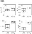
- figure 3 shows four different characteristic photovoltaic parameters (JSC (short circuit current), VOC (open circuit voltage), FF (fill factor) and PCE (photo current efficiency) of perovskite solar cells.
- JSC short circuit current
- VOC open circuit voltage
- FF fill factor
- PCE photo current efficiency
- figure 4 shows measurement of individual hole conductor layers without solar cell structure.
- the figure shows the current density of different doping concentrations at different voltages, with the result that from 0.2 mol of dopant per mol of matrix compound, a significant increase in the current density by increasing the doping concentration is obviously no longer possible.
- the Fill Factor denotes the quotient of the maximum power of a solar cell at the maximum power point and the product of open circuit voltage and short circuit current.
- the result of the measurements shows that the organometallic solar cells constructed with a hole conductor layer with the doping agent based on zinc and/or bismuth according to the invention and with an absorber layer made of a material that crystallizes in the three-dimensional perovskite structure have a very good efficiency of converting light into electricity -Show conversion.
- the present invention discloses for the first time a metal-organic solar cell, comprising an absorber layer with a compound that crystallizes in the perovskite crystal lattice, which has a lithium-poor hole conductor layer.
Landscapes
- Engineering & Computer Science (AREA)
- Chemical & Material Sciences (AREA)
- Power Engineering (AREA)
- Chemical Kinetics & Catalysis (AREA)
- Electrochemistry (AREA)
- Physics & Mathematics (AREA)
- Materials Engineering (AREA)
- Electromagnetism (AREA)
- Microelectronics & Electronic Packaging (AREA)
- Inorganic Chemistry (AREA)
- Manufacturing & Machinery (AREA)
- Life Sciences & Earth Sciences (AREA)
- Sustainable Development (AREA)
- Photovoltaic Devices (AREA)
- Inorganic Insulating Materials (AREA)
- Inorganic Compounds Of Heavy Metals (AREA)
Description
- Die Erfindung betrifft eine metallorganische Perowskit-Solarzelle, insbesondere eine mit einer Blei- oder Zinnhaltigen metallorganischen Photonen-Absorberschicht, sowie ein Herstellungsverfahren dafür.
- Bekannt sind, beispielsweise aus der
EP 2498315 A2 , organische Solarzellen, auch Plastiksolarzellen genannt, die im Gegensatz zu den anorganischen Solarzellen auf flexible Substrate und Filme aufgebaut werden können. - Seit der Demonstration der ersten organischen Solarzelle mit einem Wirkungsgrad im Prozentbereich werden organische Materialien intensiv für verschiedene elektronische und optoelektronische Bauelemente verwendet. Organische Solarzellen bestehen aus einer Folge dünner Schichten, die typischerweise zwischen 1nm bi 100 µm aufweisen. Der Bandgap von geeigneten Absorberschichten liegt beispielsweise bei zumindest 1 eV.
- Dabei gab es auch schon vielfältige Untersuchungen zu geeigneten Dotierungsmittel für die an die Absorberschicht angrenzenden Ladungsträgertransportschichten wie die Lochleiterschicht und die Elektronentransportschicht. Beispielsweise sei dazu die
EP 2443680 ,DE 102011003192 ,DE 102012209520 ,DE 102014210412 sowie dieDE 102015121844 . - Organische Solarzellen sind schon Gegenstand vielfältiger Untersuchungen gewesen, da die Aussicht, ganze Verglasungen von Hochhäusern durch Beschichtung mit organischen Solarzellen zur Stromerzeugung nutzbar zu machen, weltweit sehr verlockend ist.
- Die bekannten Plastik-Solarzellen haben als Material für die Absorberschicht konjugierte Polymere - KohlenwasserstoffPolymere in Kombination mit small molecules, beispielsweise Fullerenen, zur Ladungstrennung.
- Bekannt ist auch aus der
WO 2014/020499 ein Aufbau für eine metallorganische Perowskit-Solarzelle, bei der eine oder mehrere organisch-anorganische, hier auch als "metallorganisch" bezeichnete - Perowskit-Schichten zwischen zwei Kontaktschichten, beispielsweise Elektroden, mit denen die Perowskit-Schichten in elektrischem, vorzugsweise galvanischem Kontakt sind, angeordnet sind. - Durch den Einsatz metallorganischer Absorberschichten anstelle der rein organischen Absorberschichten, wie oben beschrieben, ergeben sich neue Herausforderungen für die Schichtabfolge der metallorganischen Solarzelle.
- In der
WO 2014/020499 wird noch davon ausgegangen, dass durch die metallorganische Absorberschicht eine Lochtransportschicht, wie sie in den organischen Solarzellen zwischen der Absorberschicht und der Elektrode vorgesehen ist, obsolet wird. - Das hat sich jedoch als nachteilig herausgestellt, so dass mittlerweile auch die metallorganische Solarzelle mit einer Absorberschicht eines im Perowskit-Kristallgitter kristallisierenden metallorganischen Materials zum schnelleren Abtransport der durch Photoneneinstrahlung getrennten Ladungsträger mit zumindest einer angrenzenden Lochtransportschicht realisiert wird.
- So ist aus den
EP 2898553 A1 ,WO 2018/005749 A1 , undUS 2015/295194 A1 eine metallorganische "p-i-n"-geschaltete Solarzelle bekannt, deren Schichtabfolge zumindest die folgenden Schichten umfasst: Transparente Elektrode, darauf ein Lochtransportmaterial, dann die Absorberschicht mit einem im dreidimensionalen Perowskit-Gitter kristallisierenden metallorganischen Absorbermaterial ABX3, dann eine Elektronentransportschicht und die Gegenelektrode. Eine in einer hier beschriebenen Solarzelle nutzbare Lochtransportschicht ist beispielsweise aus "2,2'7,7'-tetrakis-(N, N-di-p-methoxyphenylamine)9,9'-spirobifluorene" oder kurz "SpiroOMeTad" mit sehr hohen - beispielsweise 30 Mol% und höher - Konzentrationen an einem schwachen Dotierungsmittel, das Lithium-Ionen enthält. - Der Einsatz solch hoher Dotierungs-Konzentrationen von Lithium in einer metallorganischen Solarzelle bringt jedoch den Nachteil, dass diese Schichten stark hygroskopisch sind und nur geringe Stabilität aufweisen.
- Aufgabe der vorliegenden Erfindung ist es daher, anstelle oder ergänzend zum bekannten Lithium-haltigen p-Dotierungsmittel alternative p-Dotierungsmittel zur Verfügung zu stellen, deren Stabilität innerhalb der Lochleiterschicht und der gesamten metallorganischen Solarzelle höher ist. Diese Aufgabe wird durch den Gegenstand der vorliegenden Erfindung, wie er aus der Beschreibung, der Figur und den Ansprüchen offenbart wird, gelöst.
- Dementsprechend ist Gegenstand der vorliegenden Erfindung eine metallorganische Solarzelle, zumindest zwei Kontaktschichten und daran angrenzend jeweils eine halbleitende Schicht in einem Schicht-Stapel mit einer mittig angeordneten Absorberschicht aus einem metallorganischen Material, das im dreidimensionalen Perowskit-Kristallgitter kristallisiert, aufweisend, wobei die Absorberschicht Blei und/oder Zinn als Zentralatom und ein Halogenid als Anion in einer metallorganischen Verbindung umfasst, dadurch gekennzeichnet, dass die zumindest eine halbleitende Schicht zwischen der Absorberschicht und der Anode eine lochleitende Schicht ist, die ein Zink- und/oder Bismut-haltiges Dotierungsmittel umfasst.
- Außerdem ist Gegenstand der Erfindung eine Tandem-Solarzelle, entweder zwei metallorganische Solarzellen oder zumindest eine metallorganische Solarzelle mit einem Zink- und/oder Bismut-haltigem Dotierungsmittel in der Lochleiterschicht umfassend.
- Schließlich ist Gegenstand der Erfindung ein Verfahren zur Herstellung eines Schichtkörpers, eine Tandem-Solarzelle bildend, bei dem ein Schichtstapel zwei Solarzellen umfassend, vorliegt, wobei eine untere und eine obere Solarzelle durch die Herstellung aufeinander folgender Schichten hergestellt werden, dadurch gekennzeichnet, dass zumindest eine der Solarzellen eine metallorganische Solarzelle, wie sie Gegenstand der Erfindung ist, ist.
- Als metallorganische Verbindung wird vorliegend eine so genannte Komplex-Verbindung bezeichnet. Beispielsweise die im Perowskit-Kristallgitter kristallisierende Verbindung CH3NH3PbI3 ist ein Paradefall einer solchen Verbindung. Im Kristallgitter kann man eine Elementarzelle erkennen, bei der das Blei mittig als so genanntes Zentralatom in einem Kubus sitzt, wobei die organischen Liganden, wie beispielsweise das CH3NH3 die acht Ecken des Kubus, also eines Würfels, bilden. Jeweils mittig in der Fläche des Würfels sitzt dann ein Anion, beispielsweise also ein Halogenid-Anion, wie das Jodid. Wenn im Kristallgitter viele solche Zellen aneinandergrenzen, dann resultiert in der Stöchiometrie eine Summenformel von CH3NH3PbI3.
- Bezüglich der Tandem-Solarzelle hat es sich als vorteilhaft erwiesen, dass in der Tandem-Solarzelle die zwei Solarzellen aufeinander hinsichtlich ihres Absorptionsspektrums abgestimmt sind, so dass ein maximales Strahlenspektrum absorbiert wird. Dabei ist insbesondere vorteilhaft, wenn die Tandem-Solarzelle aus zwei metallorganischen Solarzellen gebildet ist, beispielsweise dadurch, dass die beiden Solarzellen sich in der Zusammensetzung des Materials, das die Absorberschicht bildet, unterscheiden.
- Abgesehen davon hat sich die Kombination einer metallorganischen Solarzelle, wie sie Gegenstand der Erfindung ist, mit einer c-Si-Solarzelle, auch als vorteilhaft erwiesen. Eine c-Si Solarzelle, ist eine Solarzelle, die kristallines Silizium in der Absorberschicht umfasst. Dabei liegt die metallorganische Solarzelle bevorzugt oben, näher an der Sonne.
- Insbesondere wird beispielsweise die c-Si-Solarzelle als Substrat zum Aufbau einer metallorganischen Solarzelle wie sie Gegenstand der Erfindung ist, eingesetzt.
- Die einzelnen Schichten des Schichtkörpers, der eine metallorganische Solarzelle oder eine Tandem-Solarzelle mit einer metallorganischen Solarzelle, bildet, können im nasschemischen Verfahren, beispielsweise durch Spin-Coating, beispielsweise aber nicht zwingend mit Lösungsmittel, hergestellt werden. Alternativ ist eine Herstellung über Dampfabscheidung, chemisch oder physikalisch, möglich.
- Allgemeine Erkenntnis der Erfindung ist es, dass entgegen den Erwartungen, die eine Dotierung mit Zink- und/oder Bismut-Verbindungen in einer spiro-OMeTAD Lochleiterschicht angrenzend an eine Perowskit-Absorberschicht aus Blei- und/oder Zinn-Komplexverbindungen als instabil erwarten lassen, sich aus Zink- und/oder Bismut-salzen mit - beispielsweise - Supersäuren, stabile Dotierungsmittel für stabile Lochleiterschichten herstellbar sind.
- Das Dotierungsmittel umfasst vorteilhafterweise neben dem Zink- und/oder Bismut-Kation noch ein Anion einer Supersäure.
- Die Lochleiterschicht umfasst dabei zumindest eine Matrix und ein Dotierungsmittel, letzteres hier auf Zink- und/oder Bismut-Basis. Die Zugabe üblicher Additive ist allerdings auch vom Umfang der Erfindung mit umfasst.
- Ein geeignetes Matrix-Material für die Lochtransportschicht einer metallorganischen Perowskit-Solarzelle ist beispielsweise ein organischer Leiter, beispielsweise das "2,2'7,7'-tetrakis-(N, N-di-p-methoxyphenylamine)9,9'-spirobifluorene" oder "spiro-OMeTAD". Durch Messungen konnte gezeigt werden, dass geringe Konzentrationen, wie beispielsweise 0,05 bis 10 mol%, insbesondere 0,1 bis 7 mol% und bevorzugt sogar nur 0,1 bis 2 mol% eines Dotierungsmittels, das Zink und/oder Bismut enthält, in einer spiro-OMeTAD Schicht genügen, um die nötigen Stromdichten in der Lochleiterschicht der Solarzelle zu erzeugen.
- Bei der Abscheidung der Lochleiterschicht nasschemisch, das heißt aus Lösung wird insbesondere die Dotierkonzentration über den Massenanteil beispielsweise eines Supersäurensalzes und den Massenanteil des Matrixmaterials in der Lösung vor der Abscheidung eingestellt. Die Volumenkonzentration des p-Dopanten in der fertig abgeschiedenen Lochleiterschicht kann von dieser Konzentration abweichen.
- Mit der erfindungsgemäßen Materialklasse der Zink- und/oder Bismut-Salzen, beispielsweise von Supersäuren, als Dotierungsmittel ist zur Herstellung der einzelnen Schichten des Schichtstapels eine nasschemische Abscheidemethode gegenüber der Abscheidung aus der Gasphase bevorzugt.
- Besonders die photonenabsorbierenden Eigenschaften für den Einsatz des p-Dotiermittels in metallorganischen Solarzellen können durch die neuen Materialien für p-Dotierung stark verbessert werden. Eine hohe Leitfähigkeit wird schon bei geringen Dotierkonzentrationen erreicht.
- Nicht einschränkende Beispiele für Supersäuren im Rahmen der vorliegenden Anmeldung sind:
-
- Fluorsulfonsäure (HSO3F)
- Fluor-Antimonsäure (HSbF6)
- Tetrafluoroborsäure (HBF4)
- Hexafluorophosphorsäure (HPF6)
- Trifluoromethylsulfonsäure (HSO3CF3)
-
- Pentacyanocyclopentadien (HC5(CN)5)
- Teilweise oder ganz fluorierte Derivate des Pentaphenylcyclopentadiens
- Penta-trifluoromethyl-pentadiens bzw. analoger Derviate
- Teilweise oder ganz fluorierte Derivate der Tetraphenylborsäure bzw. deren Cyanoderivate
- Teilweise oder ganz fluorierte Derivate der Arylsulfonsäuren bzw. deren Cyanoderivate
- Teilweise oder ganz fluorierte Derivate der Arylphosphonsäuren bzw. deren Cyanoderivate
- Anionen der Carborane wie beispielsweise [C2B10H10]2- oder [C1B11H10]-
- Die Trifluoromethylsulfonsäure (HSO3CF3) ist davon ein besonders geeigneter Vertreter.
- Polymere Matrixmaterialien für Lochtransporter, die nasschemisch zur Herstellung der Lochleiterschicht der Solarzelle abgeschieden werden können, sind, neben dem bereits erwähnten "2,2'7,7'-tetrakis-(N, N-di-p-methoxyphenylamine)9,9'-spirobifluorene" oder "spiro-OMeTAD" insbesondere auch:
- PEDOT (Poly(3,4 ethylenedioxythiophene))
- PVK (poly(9-vinylcarbazole))
- PTPD (poly (N.N-bis (4-butylphenyl)-N,N-bis (phenyl)-benzidine))
- P3HT (poly(3-hexylhtiophene))
- PANI (polyaniline)
- PTAA (Poly[bis(4-phenyl) (2,4,6-trimethylphenyl)amine]) sowie
- 9,9-Bis[4-(N,N-bis-biphenyl-4-yl-amino)phenyl]-9H-fluorene und/oder
- 4,4',4"-Tris(N-(2-naphthyl)-N-phenyl-amino)triphenylamine.
- Im Sinne der Erfindung sind auch Mischungen aus den genannten polymeren Lochtransportmaterialien.
- Als Lösungsmittel für die nasschemische Verarbeitung kommen bevorzugt organische Lösungsmittel zum Einsatz, wie zum Beispiel:
- Benzol,
- Chlorbenzol,
- Chloroform,
- Toluol,
- THF,
- Methoxypropylacetat,
- Anisol,
- Acetonitril,
- Phenetol oder
- Dioxan.
- Ein weiterer besonderer Vorteil der Erfindung besteht darin, dass die für die p-Dotierung geeignete Materialklasse der Supersäurensalze mit der Lochleiter-Matrix aus dem gleichen Lösungsmittel abscheidbar ist. Dies stellt eine signifikante Vereinfachung der Abscheideverfahren für die Herstellung der metallorganischen Solarzelle dar.
- Hinzu kommt, dass sich mit den Zink- und/oder Bismut-Salzen als Dotierungsmittel die Dotierung der Lochleiterschicht leichter herstellen lässt, insbesondere bei geringerer Prozesstemperatur, als die bereits bekannte, mit Lithium dotierten Lochtransportschichten. Die Temperatur ist bei der Herstellung der metallorganischen Solarzelle ein ganz heikler Faktor, weil die organischen Liganden und die Kristallstruktur natürlich gegenüber Temperaturerhöhung höchst sensibel reagieren. Des Weiteren wird bei diesen Dotiermaterialien keine Anwesenheit von Sauerstoff bei der Prozessierung zur Erzielung des Dotiereffekts benötigt. Dies ist vorteilhaft, da Sauerstoff sich negativ auf andere Teile des Schichtsystems der metallorganischen Solarzelle auswirkt. Beispielsweise die Herstellung einer mit Lithium-haltigem Dotierungsmittel versetzten Lochleiterschicht erfordert den Einsatz von Additiven wie tert-butylpyridine - TBP -. Dies führt zusammen mit der starken Hygroskopie der Lithium-Verbindungen zu einer indirekten Oxidation durch Luftsauerstoff.
- Nach einer vorteilhaften Ausführungsform der Tandem-Solarzelle ist die metallorganische Solarzelle die obere Solarzelle, auf die die Photonen als erstes auftreffen. Hierbei gibt es zwei Ausführungsformen - 2 Terminal und 4 Terminal Strukturen einer Tandemzelle, jeweils abhängig von der Anzahl der Kontaktstellen der Tandem-Solarzelle.
- Als Absorberschicht der metallorganischen Solarzelle wird bevorzugt eine Schicht mit einer ABX3-Stöchiometrie eingesetzt, die im dreidimensionalen Perowskit-Kristallgitter kristallisiert.
- Beispielsweise wird als metallorganische ABX3 - Verbindung ein CH3NH3PbX3 und/oder CH3NH3SnX3 eingesetzt, wobei X ein Halogenid oder Pseudohalogenid, beispielsweise ausgewählt aus der Gruppe umfassend Fluorid, Chlorid, Cyanid, Isocyanid, Bromid und/oder Jodid, sowie beliebige Kombinationen davon, sein kann. Der Perowskite Absorber kann sehr unterschiedlich zusammengesetzt sein und beispielsweise so genannte "mixing cations" wie MA, FA und/oder Cs umfassen.
- Die Halogenide/Pseudohalogenide liegen dabei als Anionen im Kristallgitter vor, der organische Ligand "(CH3NH3)+-, ebenso wie das Blei oder Zinn, als Kationen. Das Material der Absorberschicht kann auch -teilweise oder ganz- andere Verbindungen, wie z.B. die nachfolgend in einer nicht abschließenden Aufzählung genannten, umfassen:
- FA0.81Cs0.15PbI2.51Br0.45
- FA0.9Cs0.1PbI3
- Cs0.05MA0.1FA0.85Pb(I0.85Br0.15)3
- Cs0.05MA0.1FA0.85Pb(I0.85Br0.15)3
- Im Sinne der Erfindung sind auch Mischungen der genannten Verbindungen für das Absorbermaterial.
- Überraschend hat sich herausgestellt, dass der Ersatz von Lithium durch Zink und/oder Bismut im Dotierungsmittel, respektive in der Lochleiterschicht, nicht nur die Stabilität der Lochleiterschicht um einiges erhöht, sondern erste Tests haben auch gezeigt, dass die Zink- und/oder Bismut-Dotierungsmittel auch schon in wesentlich geringeren Konzentrationen in den lochleitenden Schichten auch zu höheren Leerlaufspannungen, einem hohen Füll Faktor und einer deutlich höheren Photon-Konversions-Effizienz (PCE) der Solarzellen führen. Offensichtlich ist beispielsweise Zn(TFSI)2 aktiver als LiTFSI in der Lochleitschicht, beispielsweise in spiro-MeOTAD, es leitet die Ladungsträger schneller und führt darin zu höheren Niveaus freier Ladungsträger.
- Messungen an der EPFL, Lausanne, haben gezeigt, dass die hier erstmals im Zusammenhang mit spiro-MeOTAD eingesetzten TFSI Derivate von Zink und Bismut, signifikante elektrische Verbesserungen in der Lochleiterschicht erzeugen, die nicht allein durch verbesserte Leitfähigkeit erklärbar sind.
-
Figur 1 zeigt den Aufbau einer metallorganischen Solarzelle 1, im n-i-p-Layout, zumindest folgende Schichten umfassend: Eine transparente leitfähige Elektrode 7, wie beispielsweise eine Elektrode aus dotiertem Indium Zinn Oxid oder einer anderen transparenten leitfähigen Schicht. Diese kann auf einem Träger wie beispielsweise Glas aufgebracht sein oder selbsttragend ausgebildet sein. - Auf dieser Schicht ist eine n-leitende Schicht 2, beispielsweise aus Titandioxid. Darauf befindet sich die Absorberschicht, beispielsweise die Schicht 3 aus CH3NH3PbI3 und/oder CH3NH3SnI3 in der dreidimensionalen Perowskit-Struktur vorliegend. Die Absorberschicht 3 kann dabei planar oder in Form einer Gerüststruktur vorliegen. Angrenzend an diese Schicht befindet sich die Lochtransportschicht 4, die vorliegend aus einem Matrixmaterial, beispielsweise dem spiro-MeOTAD mit einem Dotierungsmittel, das Zink und/oder Bismut enthält, insbesondere mit Zn(TFSI)2 und/oder Bi(TFSI)3, wie es aus der
DE 10 2015 121844 bekannt ist, ist. - Im Falle des Dotierungsmittels Zn (TFSI)2 und/oder Bi(TFSI)3 ist nach einer vorteilhaften Ausführungsform zwischen der Lochleiterschicht 4 und der Absorberschicht 3 noch eine dünne Sperrschicht, hier nicht gezeigt, vorgesehen. Dies kann vorteilhaft sein, falls das Dotierungsmittel die Tendenz zeigt, in die Absorberschicht hinein zu diffundieren.
- Anstelle oder zusammen mit dem Zn(TFSI)2 liegen beispielsweise auch Bi-(3,5-TFMBZ)3, Bismut(III) tris (3,5-bistrifluormethyl)benzoat, Bi(4-pFbz)3, Bismut (III) tris(4-pentafluoro)benzoat, K(TFSI), K(I)bis(trifluoromethanesulfonyl)imide und/oder Zn(II)bis (trifluoromethanesulfonyl)imide und/oder Natrium(I)bis(trifluoromethanesulfonyl)imid als Dotierungsmittel vor.
- Darüber hinaus können auch Tri-Fluormethan-sulfonate wie Zn (TFMS)2 vorteilhaft als Dotiermittel eingesetzt werden. Alternativ oder ergänzend können auch sogenannte Ionische Flüssigkeiten "Ionic liquids" als effektive Dotiermittel genutzt werden.
- Abschließend befindet sich auf der Lochleiterschicht 4 noch die Gegenelektrode, beispielsweise aus Aluminium, Silber und/oder Gold.
- Der gesamte Aufbau ist bevorzugt durch eine Verkapselung 6 vor Feuchte und/oder Luft geschützt.
-
Figur 2 zeigt den Anstieg der Leerlaufspannung einer metallorganischen Solarzelle beim Wechsel von einer mit Lithium dotierten Lochleiterschicht zu einer mit Zink dotierten Lochleiterschicht. -
Figur 3 zeigt vier verschiedene charakteristische photovoltaische Parameter (JSC (Kurzschlussstrom), VOC (Leerlaufspannung), FF (Füllfaktor)und PCE (photo current efficiency (Fotostromeffizienz)) von Perowskit Solarzellen. Hier im Vergleich zwischen einer Perowskit Solarzelle mit spiro-MeOTAD /LiTFSI (schwarz) und spiro-MeOTAD /Zn(TFSI)2 (rot) als Lochleiterschicht. - Diese Messungen zeigen jeweils die metallorganischen Solarzellen mit Lithium-dotierten und Zink dotierten Lochleiterschichten bei ansonsten gleichem Aufbau und Messbedingungen im Vergleich. So machen diese Messungen deutlich, dass die mit einer Zink dotierten Lochleiterschicht aufgebauten Solarzellen den mit herkömmlichem Lithium dotierten zumindest gleichwertig sind. Dies ist umso erstaunlicher, als die Dotierungskonzentration vom Lithium zum Zink und/oder Bismut deutlich sinkt, was einen deutlichen wirtschaftlichen Vorteil bringt.
-
Figur 4 zeigt Messung einzelner Lochleiterschichten ohne Solarzellenaufbau. Zu erkennen ist in der Figur die Stromdichte verschiedener Dotierungskonzentrationen bei verschiedenen Spannungen mit dem Ergebnis, dass ab 0,2 mol Dotierungsmittel pro mol Matrixverbindung offensichtlich keine signifikante Steigerung der Stromdichte durch Erhöhung der Dotierungskonzentration mehr möglich ist. - In
Figur 4 sind neben den Strom-Spannungskurven, die links zu sehen sind, noch rechts die entsprechenden photovoltaischen Parameter wie JSC, VOC, FF und PCE in Abhängigkeit der Konzentration des Dotiermittels Zn (TFSI)2 im Matrixmaterial Spiro-MeOTAD. - Dabei fällt vor allem auf, dass der "Fill Faktor" (Füllfaktor) signifikant verbessert wurde. Der Füllfaktor bezeichnet den Quotienten aus der maximalen Leistung einer Solarzelle am Maximum Power Point und dem Produkt aus Leerlaufspannung und Kurzschlussstrom.
- Im Ganzen ergibt das Ergebnis der Messungen, dass die mit einer Lochleiterschicht mit dem erfindungsgemäßen Dotierungsmittel auf Zink- und/oder Bismut-Basis aufgebauten metallorganischen Solarzellen mit einer Absorberschicht aus einem in der dreidimensionalen Perowskit-Struktur kristallisierenden Material eine sehr gute Effizienz der Licht in Elektrizitäts-Umwandlung zeigen.
- In
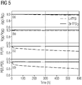
Figur 5 schließlich wird die Stabilität der mit Zink einerseits und mit Lithium andererseits hergestellten Lochleiterschichten verglichen. Es zeigt sich, dass die herkömmlichen, mit Lithium dotierten Lochleiterschichten weit weniger stabil sind als die entsprechenden Lochleiterschichten mit Zink und/oder Bismut. Das hängt unter anderem damit zusammen, dass das kleine Lithium-Ion natürlich unter Temperaturerhöhung und/oder im elektrischen Feld leichter und schneller diffundiert und damit die Homogenität der Lochleiterschichten herabsetzt. Insbesondere bei der PCE - Power Conversion Efficiency - /PCE-Messung zeigt sich deutlich, wie mit steigender Stundenzahl die Effizienz der mit Lithium dotierten Lochleiterschicht nachlässt. - Die vorliegende Erfindung offenbart erstmals eine metallorganische Solarzelle, eine Absorberschicht mit einer im Perowskit-Kristallgitter kristallisierenden Verbindung umfassend, die eine Lithium-arme Lochleiterschicht aufweist.
Claims (13)
- Metallorganische Solarzelle, zumindest zwei Kontaktschichten (5,7), wobei eine Kontaktschicht als Anode (5) ausgebildet ist, und daran angrenzend jeweils eine halbleitende Schicht (2,4) in einem Schicht-Stapel mit einer mittig angeordneten Absorberschicht (3) aus einem metallorganischen Material, das im dreidimensionalen Perowskit-Kristallgitter kristallisiert, aufweisend, wobei die Absorberschicht (3) Blei als Zentralatom und ein Halogenid als Anion in einer metallorganischen Verbindung umfasst, dadurch gekennzeichnet, dass die zumindest eine halbleitende Schicht (4) zwischen der Absorberschicht (3) und der Anode (5) eine lochleitende Schicht ist, die ein Zink-haltiges Dotierungsmittel umfasst.
- Metallorganische Solarzelle, zumindest zwei Kontaktschichten (5,7), wobei eine Kontaktschicht als Anode (5) ausgebildet ist, und daran angrenzend jeweils eine halbleitende Schicht (2,4) in einem Schicht-Stapel mit einer mittig angeordneten Absorberschicht (3) aus einem metallorganischen Material, das im dreidimensionalen Perowskit-Kristallgitter kristallisiert, aufweisend, wobei die Absorberschicht (3) Zinn als Zentralatom und ein Halogenid als Anion in einer metallorganischen Verbindung umfasst, dadurch gekennzeichnet, dass die zumindest eine halbleitende Schicht (4) zwischen der Absorberschicht (3) und der Anode (5) eine lochleitende Schicht ist, die ein Bismut-haltiges Dotierungsmittel umfasst.
- Solarzelle nach einem der Ansprüche 1 oder 2, wobei im Dotierungsmittel die Zink- oder Bismut-Verbindung das Salz einer Supersäure ist.
- Solarzelle nach einem der Ansprüche 1 bis 3, wobei die Solarzelle eine Diffusionssperrschicht zwischen der Absorberschicht und einer halbleitenden Schicht umfasst.
- Solarzelle nach Anspruch 4, wobei die Diffusionssperrschicht eine Schichtdicke von kleiner 150nm aufweist.
- Solarzelle nach einem der Ansprüche 1 bis 5, die im Matrixmaterial der Lochleiterschicht eine oder mehrere Verbindungen, ausgewählt aus der Gruppe folgender Verbindungen:spiro-OMeTAD - 2,2'7,7'-tetrakis-(N, N-di-p-methoxyphenylamine)9,9'-spirobifluorene,PEDOT - poly(3,4 ethylenedioxythiophene),PVK - poly(9-vinylcarbazole),PTPD - poly(N.N-bis(4-butylphenyl)-N,N-bis(phenyl)-benzidine),P3HT - poly(3-hexylhtiophene),PANI - polyaniline,PTAA - Poly[bis(4-phenyl)(2,4,6-trimethylphenyl)amine], 9,9-Bis[4-(N,N-bis-biphenyl-4-yl-amino)phenyl]-9H-fluorene, 4,4',4"-Tris(N-(2-naphthyl)-N-phenyl-amino)triphenylamine und/oder ionische Flüssigkeiten, sowie Mischungen der oben genannten Verbindungen, umfasst.
- Solarzelle nach einem der Ansprüche 1 bis 6, wobei die Absorberschicht einen Metallkomplex mit Zinn und/oder Blei als Zentralatom umfasst, der mindestens ein Anion in Form eines Halogenids oder Pseudohalogenids, ausgewählt aus der Gruppe der folgenden Elemente: Fluorid, Chlorid, Bromid, Jodid, Cyanid, Isocyanid, enthält.
- Solarzelle nach einem der Ansprüche 1 bis 7, wobei die Absorberschicht einen Metallkomplex mit Zinn und/oder Blei als Zentralatom umfasst, an dem ein (CH3NH3)+- Ligand koordiniert vorliegt.
- Tandem-Solarzelle, zumindest zwei aufeinander aufbauende Solarzellen in einem Schicht-Stapel umfassend, wobei eine Solarzelle eine metallorganische Solarzelle nach einem der Ansprüche 1 bis 8 ist.
- Tandem-Solarzelle nach Anspruch 9, wobei die metallorganische Solarzelle nach einem der Ansprüche 1 bis 9 die obere Solarzelle, auf die die Photonen als erstes auftreffen, ist.
- Tandem-Solarzelle nach einem der Ansprüche 9 oder 10, die eine Solarzelle mit kristallinem Silizium in der Absorberschicht umfasst.
- Tandemzellen nach einem der Ansprüche 9 bis 11, die zwei metallorganische Solarzellen nach einem der Ansprüche 1 bis 8 umfasst, wobei die beiden Solarzellen sich in der Zusammensetzung des Materials, das die Absorberschicht bildet, unterscheiden.
- Verfahren zur Herstellung eines Schichtkörpers, eine Tandem-Solarzelle bildend, bei dem ein Schichtstapel zwei Solarzellen umfassend durch Schichtabscheidung im nasschemischen Verfahren herstellbar ist, wobei eine untere und eine obere Solarzelle durch die Herstellung aufeinander folgender Schichten hergestellt werden, dadurch gekennzeichnet, dass eine der Solarzellen eine metallorganische Solarzelle nach einem der Ansprüche 1 bis 8 ist.
Applications Claiming Priority (2)
| Application Number | Priority Date | Filing Date | Title |
|---|---|---|---|
| DE102018212305.5A DE102018212305A1 (de) | 2018-07-24 | 2018-07-24 | Metallorganische Perowskit-Solarzelle, Tandem-Solarzelle sowie Herstellungsverfahren dazu |
| PCT/EP2019/068247 WO2020020620A1 (de) | 2018-07-24 | 2019-07-08 | Metallorganische perowskit-solarzelle, tandem-solarzelle sowie herstellungsverfahren dazu |
Publications (2)
| Publication Number | Publication Date |
|---|---|
| EP3797441A1 EP3797441A1 (de) | 2021-03-31 |
| EP3797441B1 true EP3797441B1 (de) | 2022-06-08 |
Family
ID=67480150
Family Applications (1)
| Application Number | Title | Priority Date | Filing Date |
|---|---|---|---|
| EP19745981.1A Active EP3797441B1 (de) | 2018-07-24 | 2019-07-08 | Metallorganische perowskit-solarzelle, tandem-solarzelle sowie herstellungsverfahren dazu |
Country Status (9)
| Country | Link |
|---|---|
| US (1) | US20210249196A1 (de) |
| EP (1) | EP3797441B1 (de) |
| CN (1) | CN112534596B (de) |
| AU (1) | AU2019312457B2 (de) |
| DE (1) | DE102018212305A1 (de) |
| ES (1) | ES2926017T3 (de) |
| MA (1) | MA52711B1 (de) |
| SA (1) | SA521421077B1 (de) |
| WO (1) | WO2020020620A1 (de) |
Families Citing this family (2)
| Publication number | Priority date | Publication date | Assignee | Title |
|---|---|---|---|---|
| CN113707816B (zh) * | 2021-08-24 | 2023-07-04 | 江苏盛开高新材料有限公司 | 一种钙钛矿太阳能电池的制备方法 |
| WO2024054299A2 (en) * | 2022-07-16 | 2024-03-14 | Board Of Trustees Of Michigan State University | Multivalent organic salts for photovoltaics |
Family Cites Families (14)
| Publication number | Priority date | Publication date | Assignee | Title |
|---|---|---|---|---|
| DE102009022117A1 (de) | 2009-05-20 | 2010-11-25 | Siemens Aktiengesellschaft | Material für eine Lochtransportschicht mit p-Dotierung |
| DE102011003192B4 (de) | 2011-01-26 | 2015-12-24 | Siemens Aktiengesellschaft | Halbleiterbauelement und Verfahren zu seiner Herstellung |
| DE102011013897A1 (de) | 2011-03-11 | 2012-09-13 | Technische Universität Dresden | Organische Solarzelle |
| DE102012209520A1 (de) | 2012-06-06 | 2013-12-12 | Osram Opto Semiconductors Gmbh | Metallkomplexe als p-Dotanden für organische elektronische Matrixmaterialien |
| EP2693503A1 (de) | 2012-08-03 | 2014-02-05 | Ecole Polytechnique Fédérale de Lausanne (EPFL) | Organometallische Halid-Perovskit-Heteroverbindungssolarzelle und Herstellung davon |
| AU2013319979B2 (en) | 2012-09-18 | 2016-08-25 | Oxford Photovoltaics Limited | Optoelectronic device |
| GB201309668D0 (en) * | 2013-05-30 | 2013-07-17 | Isis Innovation | Organic semiconductor doping process |
| EP3132472A1 (de) * | 2014-04-15 | 2017-02-22 | Northwestern University | Bleifreie organisch-anorganische festkörperhalogenid-perovskitphotovoltaikzellen |
| DE102014210412A1 (de) | 2014-06-03 | 2015-12-03 | Siemens Aktiengesellschaft | p-Dotierende Vernetzung organischer Lochleiter |
| DE102015121844A1 (de) * | 2015-12-15 | 2017-06-22 | Osram Oled Gmbh | Organisches elektronisches Bauelement und Verwendung eines fluorierten Sulfonimid-Metallsalzes |
| WO2018005749A1 (en) * | 2016-06-29 | 2018-01-04 | Alliance For Sustainable Energy, Llc | Methods for making perovskite solar cells having improved hole-transport layers |
| WO2018007586A1 (en) * | 2016-07-07 | 2018-01-11 | Technische Universiteit Eindhoven | Perovskite contacting passivating barrier layer for solar cells |
| KR20180047382A (ko) * | 2016-10-31 | 2018-05-10 | 고려대학교 산학협력단 | 확산 방지막을 이용한 페로브스카이트 태양전지 및 이의 제조방법 |
| CN108063186A (zh) * | 2017-11-20 | 2018-05-22 | 济南大学 | 锌掺杂氧化镍空穴传输层反置钙钛矿太阳能电池及制备方法 |
-
2018
- 2018-07-24 DE DE102018212305.5A patent/DE102018212305A1/de not_active Withdrawn
-
2019
- 2019-07-08 ES ES19745981T patent/ES2926017T3/es active Active
- 2019-07-08 EP EP19745981.1A patent/EP3797441B1/de active Active
- 2019-07-08 AU AU2019312457A patent/AU2019312457B2/en active Active
- 2019-07-08 WO PCT/EP2019/068247 patent/WO2020020620A1/de not_active Ceased
- 2019-07-08 CN CN201980049175.2A patent/CN112534596B/zh active Active
- 2019-07-08 US US17/261,001 patent/US20210249196A1/en not_active Abandoned
- 2019-07-08 MA MA52711A patent/MA52711B1/fr unknown
-
2021
- 2021-01-21 SA SA521421077A patent/SA521421077B1/ar unknown
Also Published As
| Publication number | Publication date |
|---|---|
| AU2019312457B2 (en) | 2021-05-27 |
| WO2020020620A1 (de) | 2020-01-30 |
| DE102018212305A1 (de) | 2020-01-30 |
| EP3797441A1 (de) | 2021-03-31 |
| ES2926017T3 (es) | 2022-10-21 |
| MA52711A (fr) | 2021-03-31 |
| CN112534596A (zh) | 2021-03-19 |
| MA52711B1 (fr) | 2022-08-31 |
| AU2019312457A1 (en) | 2021-02-11 |
| SA521421077B1 (ar) | 2025-04-20 |
| CN112534596B (zh) | 2023-09-12 |
| US20210249196A1 (en) | 2021-08-12 |
Similar Documents
| Publication | Publication Date | Title |
|---|---|---|
| Yang et al. | Achievements, challenges, and future prospects for industrialization of perovskite solar cells | |
| US11335513B2 (en) | Passivation of defects in perovskite materials for improved solar cell efficiency and stability | |
| Tiep et al. | Recent advances in improving the stability of perovskite solar cells | |
| DE102007018456B4 (de) | Verwendung von Hauptgruppenelementhalogeniden und/oder -pseudohalogeniden, organisches halbleitendes Matrixmaterial, elektronische und optoelektronische Bauelemente | |
| US10332688B2 (en) | Methods for making perovskite solar cells having improved hole-transport layers | |
| DE102008051737B4 (de) | Quadratisch planare Übergangsmetallkomplexe, organische halbleitende Materialien sowie elektronische oder optoelektronische Bauelemente, die diese umfassen und Verwendung derselben | |
| JP6935175B2 (ja) | 膜、光デバイス、電子デバイス、光電変換装置、および膜の製造方法 | |
| KR20190141742A (ko) | 장기 고 가동 안정성을 갖는 무기 홀 도체 기초 퍼로브스카이트 광전 전환 장치 | |
| WO2007134873A1 (de) | Verwendung von quadratisch planaren übergangsmetallkomplexen als dotand | |
| EP2002492A1 (de) | Verwendung von heterocyclischen radikalen zur dotierung von organischen halbeitern | |
| EP3385269B1 (de) | Organisch-anorganischer hybrider perowskit, verfahren zur herstellung davon und solarzelle damit | |
| DE112020007073T5 (de) | Verarbeitung von effizienten perovskit-solarzellen in feuchter luft basierend auf polymerisierbaren ionischen flüssigkeiten und salzen | |
| DE102006054523B4 (de) | Dithiolenübergangsmetallkomplexe und Selen-analoge Verbindungen, deren Verwendung als Dotand, organisches halbleitendes Material enthaltend die Komplexe, sowie elektronische oder optoelektronisches Bauelement enthaltend einen Komplex | |
| EP2659529B1 (de) | Optoelektronisches bauelement mit dotierten schichten | |
| EP3797441B1 (de) | Metallorganische perowskit-solarzelle, tandem-solarzelle sowie herstellungsverfahren dazu | |
| Jamesh et al. | Advancement of technology towards developing perovskite-based solar cells for renewable energy harvesting and energy transformation applications | |
| EP2132800B1 (de) | Organische strahlungsemittierende vorrichtung und ein herstellungsverfahren für die vorrichtung | |
| WO2020020622A1 (de) | Metallorganische perowskit-solarzelle, tandem-solarzelle sowie herstellungsverfahren dazu | |
| US12334279B2 (en) | Compositions and methods for modifying perovskite surfaces | |
| CN118475207A (zh) | 钙钛矿太阳能电池及其制备方法、叠层电池 | |
| WO2016116205A1 (de) | Proazaphosphatrane als n-dotierstoffe in der organischen elektronik | |
| KR102022688B1 (ko) | 흡수체로서 3-피콜리뉴밀암모늄을 포함하는 화합물, 이의 제조 방법 및 이를 포함하는 태양전지 |
Legal Events
| Date | Code | Title | Description |
|---|---|---|---|
| STAA | Information on the status of an ep patent application or granted ep patent |
Free format text: STATUS: UNKNOWN |
|
| STAA | Information on the status of an ep patent application or granted ep patent |
Free format text: STATUS: THE INTERNATIONAL PUBLICATION HAS BEEN MADE |
|
| PUAI | Public reference made under article 153(3) epc to a published international application that has entered the european phase |
Free format text: ORIGINAL CODE: 0009012 |
|
| STAA | Information on the status of an ep patent application or granted ep patent |
Free format text: STATUS: REQUEST FOR EXAMINATION WAS MADE |
|
| 17P | Request for examination filed |
Effective date: 20201222 |
|
| AK | Designated contracting states |
Kind code of ref document: A1 Designated state(s): AL AT BE BG CH CY CZ DE DK EE ES FI FR GB GR HR HU IE IS IT LI LT LU LV MC MK MT NL NO PL PT RO RS SE SI SK SM TR |
|
| AX | Request for extension of the european patent |
Extension state: BA ME |
|
| RAP1 | Party data changed (applicant data changed or rights of an application transferred) |
Owner name: SIEMENS ENERGY GLOBAL GMBH & CO. KG |
|
| DAX | Request for extension of the european patent (deleted) | ||
| RAV | Requested validation state of the european patent: fee paid |
Extension state: TN Effective date: 20201222 Extension state: MA Effective date: 20201222 |
|
| GRAP | Despatch of communication of intention to grant a patent |
Free format text: ORIGINAL CODE: EPIDOSNIGR1 |
|
| STAA | Information on the status of an ep patent application or granted ep patent |
Free format text: STATUS: GRANT OF PATENT IS INTENDED |
|
| INTG | Intention to grant announced |
Effective date: 20220127 |
|
| GRAS | Grant fee paid |
Free format text: ORIGINAL CODE: EPIDOSNIGR3 |
|
| GRAA | (expected) grant |
Free format text: ORIGINAL CODE: 0009210 |
|
| STAA | Information on the status of an ep patent application or granted ep patent |
Free format text: STATUS: THE PATENT HAS BEEN GRANTED |
|
| AK | Designated contracting states |
Kind code of ref document: B1 Designated state(s): AL AT BE BG CH CY CZ DE DK EE ES FI FR GB GR HR HU IE IS IT LI LT LU LV MC MK MT NL NO PL PT RO RS SE SI SK SM TR |
|
| REG | Reference to a national code |
Ref country code: TN Ref legal event code: VAGR Ref document number: TN/P/2022/000296 Country of ref document: TN |
|
| REG | Reference to a national code |
Ref country code: AT Ref legal event code: REF Ref document number: 1497537 Country of ref document: AT Kind code of ref document: T Effective date: 20220615 Ref country code: CH Ref legal event code: EP |
|
| REG | Reference to a national code |
Ref country code: DE Ref legal event code: R096 Ref document number: 502019004601 Country of ref document: DE |
|
| REG | Reference to a national code |
Ref country code: IE Ref legal event code: FG4D Free format text: LANGUAGE OF EP DOCUMENT: GERMAN |
|
| REG | Reference to a national code |
Ref country code: MA Ref legal event code: VAGR Ref document number: 52711 Country of ref document: MA Kind code of ref document: B1 |
|
| REG | Reference to a national code |
Ref country code: LT Ref legal event code: MG9D |
|
| REG | Reference to a national code |
Ref country code: NL Ref legal event code: MP Effective date: 20220608 |
|
| REG | Reference to a national code |
Ref country code: ES Ref legal event code: FG2A Ref document number: 2926017 Country of ref document: ES Kind code of ref document: T3 Effective date: 20221021 |
|
| PG25 | Lapsed in a contracting state [announced via postgrant information from national office to epo] |
Ref country code: SE Free format text: LAPSE BECAUSE OF FAILURE TO SUBMIT A TRANSLATION OF THE DESCRIPTION OR TO PAY THE FEE WITHIN THE PRESCRIBED TIME-LIMIT Effective date: 20220608 Ref country code: NO Free format text: LAPSE BECAUSE OF FAILURE TO SUBMIT A TRANSLATION OF THE DESCRIPTION OR TO PAY THE FEE WITHIN THE PRESCRIBED TIME-LIMIT Effective date: 20220908 Ref country code: LT Free format text: LAPSE BECAUSE OF FAILURE TO SUBMIT A TRANSLATION OF THE DESCRIPTION OR TO PAY THE FEE WITHIN THE PRESCRIBED TIME-LIMIT Effective date: 20220608 Ref country code: HR Free format text: LAPSE BECAUSE OF FAILURE TO SUBMIT A TRANSLATION OF THE DESCRIPTION OR TO PAY THE FEE WITHIN THE PRESCRIBED TIME-LIMIT Effective date: 20220608 Ref country code: GR Free format text: LAPSE BECAUSE OF FAILURE TO SUBMIT A TRANSLATION OF THE DESCRIPTION OR TO PAY THE FEE WITHIN THE PRESCRIBED TIME-LIMIT Effective date: 20220909 Ref country code: FI Free format text: LAPSE BECAUSE OF FAILURE TO SUBMIT A TRANSLATION OF THE DESCRIPTION OR TO PAY THE FEE WITHIN THE PRESCRIBED TIME-LIMIT Effective date: 20220608 Ref country code: BG Free format text: LAPSE BECAUSE OF FAILURE TO SUBMIT A TRANSLATION OF THE DESCRIPTION OR TO PAY THE FEE WITHIN THE PRESCRIBED TIME-LIMIT Effective date: 20220908 |
|
| REG | Reference to a national code |
Ref country code: DE Ref legal event code: R079 Ref document number: 502019004601 Country of ref document: DE Free format text: PREVIOUS MAIN CLASS: H01L0051420000 Ipc: H10K0030000000 |
|
| PG25 | Lapsed in a contracting state [announced via postgrant information from national office to epo] |
Ref country code: RS Free format text: LAPSE BECAUSE OF FAILURE TO SUBMIT A TRANSLATION OF THE DESCRIPTION OR TO PAY THE FEE WITHIN THE PRESCRIBED TIME-LIMIT Effective date: 20220608 Ref country code: LV Free format text: LAPSE BECAUSE OF FAILURE TO SUBMIT A TRANSLATION OF THE DESCRIPTION OR TO PAY THE FEE WITHIN THE PRESCRIBED TIME-LIMIT Effective date: 20220608 |
|
| PG25 | Lapsed in a contracting state [announced via postgrant information from national office to epo] |
Ref country code: NL Free format text: LAPSE BECAUSE OF FAILURE TO SUBMIT A TRANSLATION OF THE DESCRIPTION OR TO PAY THE FEE WITHIN THE PRESCRIBED TIME-LIMIT Effective date: 20220608 |
|
| PG25 | Lapsed in a contracting state [announced via postgrant information from national office to epo] |
Ref country code: SM Free format text: LAPSE BECAUSE OF FAILURE TO SUBMIT A TRANSLATION OF THE DESCRIPTION OR TO PAY THE FEE WITHIN THE PRESCRIBED TIME-LIMIT Effective date: 20220608 Ref country code: SK Free format text: LAPSE BECAUSE OF FAILURE TO SUBMIT A TRANSLATION OF THE DESCRIPTION OR TO PAY THE FEE WITHIN THE PRESCRIBED TIME-LIMIT Effective date: 20220608 Ref country code: RO Free format text: LAPSE BECAUSE OF FAILURE TO SUBMIT A TRANSLATION OF THE DESCRIPTION OR TO PAY THE FEE WITHIN THE PRESCRIBED TIME-LIMIT Effective date: 20220608 Ref country code: PT Free format text: LAPSE BECAUSE OF FAILURE TO SUBMIT A TRANSLATION OF THE DESCRIPTION OR TO PAY THE FEE WITHIN THE PRESCRIBED TIME-LIMIT Effective date: 20221010 Ref country code: EE Free format text: LAPSE BECAUSE OF FAILURE TO SUBMIT A TRANSLATION OF THE DESCRIPTION OR TO PAY THE FEE WITHIN THE PRESCRIBED TIME-LIMIT Effective date: 20220608 Ref country code: CZ Free format text: LAPSE BECAUSE OF FAILURE TO SUBMIT A TRANSLATION OF THE DESCRIPTION OR TO PAY THE FEE WITHIN THE PRESCRIBED TIME-LIMIT Effective date: 20220608 |
|
| PG25 | Lapsed in a contracting state [announced via postgrant information from national office to epo] |
Ref country code: PL Free format text: LAPSE BECAUSE OF FAILURE TO SUBMIT A TRANSLATION OF THE DESCRIPTION OR TO PAY THE FEE WITHIN THE PRESCRIBED TIME-LIMIT Effective date: 20220608 Ref country code: IS Free format text: LAPSE BECAUSE OF FAILURE TO SUBMIT A TRANSLATION OF THE DESCRIPTION OR TO PAY THE FEE WITHIN THE PRESCRIBED TIME-LIMIT Effective date: 20221008 |
|
| REG | Reference to a national code |
Ref country code: CH Ref legal event code: PL |
|
| RAP4 | Party data changed (patent owner data changed or rights of a patent transferred) |
Owner name: SIEMENS ENERGY GLOBAL GMBH & CO. KG |
|
| REG | Reference to a national code |
Ref country code: DE Ref legal event code: R097 Ref document number: 502019004601 Country of ref document: DE |
|
| REG | Reference to a national code |
Ref country code: BE Ref legal event code: MM Effective date: 20220731 |
|
| PG25 | Lapsed in a contracting state [announced via postgrant information from national office to epo] |
Ref country code: MC Free format text: LAPSE BECAUSE OF FAILURE TO SUBMIT A TRANSLATION OF THE DESCRIPTION OR TO PAY THE FEE WITHIN THE PRESCRIBED TIME-LIMIT Effective date: 20220608 Ref country code: AL Free format text: LAPSE BECAUSE OF FAILURE TO SUBMIT A TRANSLATION OF THE DESCRIPTION OR TO PAY THE FEE WITHIN THE PRESCRIBED TIME-LIMIT Effective date: 20220608 |
|
| PLBE | No opposition filed within time limit |
Free format text: ORIGINAL CODE: 0009261 |
|
| STAA | Information on the status of an ep patent application or granted ep patent |
Free format text: STATUS: NO OPPOSITION FILED WITHIN TIME LIMIT |
|
| PG25 | Lapsed in a contracting state [announced via postgrant information from national office to epo] |
Ref country code: LU Free format text: LAPSE BECAUSE OF NON-PAYMENT OF DUE FEES Effective date: 20220708 Ref country code: LI Free format text: LAPSE BECAUSE OF NON-PAYMENT OF DUE FEES Effective date: 20220731 Ref country code: DK Free format text: LAPSE BECAUSE OF FAILURE TO SUBMIT A TRANSLATION OF THE DESCRIPTION OR TO PAY THE FEE WITHIN THE PRESCRIBED TIME-LIMIT Effective date: 20220608 Ref country code: CH Free format text: LAPSE BECAUSE OF NON-PAYMENT OF DUE FEES Effective date: 20220731 |
|
| 26N | No opposition filed |
Effective date: 20230310 |
|
| PG25 | Lapsed in a contracting state [announced via postgrant information from national office to epo] |
Ref country code: SI Free format text: LAPSE BECAUSE OF FAILURE TO SUBMIT A TRANSLATION OF THE DESCRIPTION OR TO PAY THE FEE WITHIN THE PRESCRIBED TIME-LIMIT Effective date: 20220608 Ref country code: BE Free format text: LAPSE BECAUSE OF NON-PAYMENT OF DUE FEES Effective date: 20220731 |
|
| PG25 | Lapsed in a contracting state [announced via postgrant information from national office to epo] |
Ref country code: IE Free format text: LAPSE BECAUSE OF NON-PAYMENT OF DUE FEES Effective date: 20220708 Ref country code: FR Free format text: LAPSE BECAUSE OF NON-PAYMENT OF DUE FEES Effective date: 20220808 |
|
| VSFP | Annual fee paid to validation state [announced via postgrant information from national office to epo] |
Ref country code: TN Payment date: 20220731 Year of fee payment: 4 |
|
| GBPC | Gb: european patent ceased through non-payment of renewal fee |
Effective date: 20230708 |
|
| PG25 | Lapsed in a contracting state [announced via postgrant information from national office to epo] |
Ref country code: MK Free format text: LAPSE BECAUSE OF FAILURE TO SUBMIT A TRANSLATION OF THE DESCRIPTION OR TO PAY THE FEE WITHIN THE PRESCRIBED TIME-LIMIT Effective date: 20220608 Ref country code: CY Free format text: LAPSE BECAUSE OF FAILURE TO SUBMIT A TRANSLATION OF THE DESCRIPTION OR TO PAY THE FEE WITHIN THE PRESCRIBED TIME-LIMIT Effective date: 20220608 Ref country code: GB Free format text: LAPSE BECAUSE OF NON-PAYMENT OF DUE FEES Effective date: 20230708 |
|
| PG25 | Lapsed in a contracting state [announced via postgrant information from national office to epo] |
Ref country code: HU Free format text: LAPSE BECAUSE OF FAILURE TO SUBMIT A TRANSLATION OF THE DESCRIPTION OR TO PAY THE FEE WITHIN THE PRESCRIBED TIME-LIMIT; INVALID AB INITIO Effective date: 20190708 |
|
| PG25 | Lapsed in a contracting state [announced via postgrant information from national office to epo] |
Ref country code: MT Free format text: LAPSE BECAUSE OF FAILURE TO SUBMIT A TRANSLATION OF THE DESCRIPTION OR TO PAY THE FEE WITHIN THE PRESCRIBED TIME-LIMIT Effective date: 20220608 |
|
| PG25 | Lapsed in a contracting state [announced via postgrant information from national office to epo] |
Ref country code: BG Free format text: LAPSE BECAUSE OF FAILURE TO SUBMIT A TRANSLATION OF THE DESCRIPTION OR TO PAY THE FEE WITHIN THE PRESCRIBED TIME-LIMIT Effective date: 20220608 |
|
| PG25 | Lapsed in a contracting state [announced via postgrant information from national office to epo] |
Ref country code: BG Free format text: LAPSE BECAUSE OF FAILURE TO SUBMIT A TRANSLATION OF THE DESCRIPTION OR TO PAY THE FEE WITHIN THE PRESCRIBED TIME-LIMIT Effective date: 20220608 |
|
| PGFP | Annual fee paid to national office [announced via postgrant information from national office to epo] |
Ref country code: TR Payment date: 20250619 Year of fee payment: 7 |
|
| REG | Reference to a national code |
Ref country code: AT Ref legal event code: MM01 Ref document number: 1497537 Country of ref document: AT Kind code of ref document: T Effective date: 20240708 |
|
| PGFP | Annual fee paid to national office [announced via postgrant information from national office to epo] |
Ref country code: ES Payment date: 20250812 Year of fee payment: 7 |
|
| PGFP | Annual fee paid to national office [announced via postgrant information from national office to epo] |
Ref country code: DE Payment date: 20250728 Year of fee payment: 7 |
|
| PGFP | Annual fee paid to national office [announced via postgrant information from national office to epo] |
Ref country code: IT Payment date: 20250721 Year of fee payment: 7 |
|
| PG25 | Lapsed in a contracting state [announced via postgrant information from national office to epo] |
Ref country code: AT Free format text: LAPSE BECAUSE OF NON-PAYMENT OF DUE FEES Effective date: 20240708 |
|
| VSFP | Annual fee paid to validation state [announced via postgrant information from national office to epo] |
Ref country code: MA Payment date: 20230704 Year of fee payment: 5 |
|
| VSFP | Annual fee paid to validation state [announced via postgrant information from national office to epo] |
Ref country code: MA Payment date: 20220701 Year of fee payment: 4 |
|
| VSFP | Annual fee paid to validation state [announced via postgrant information from national office to epo] |
Ref country code: MA Payment date: 20240701 Year of fee payment: 6 |
|
| VSFP | Annual fee paid to validation state [announced via postgrant information from national office to epo] |
Ref country code: MA Payment date: 20250813 Year of fee payment: 7 |
|
| PGFP | Annual fee paid to national office [announced via postgrant information from national office to epo] |
Ref country code: AT Payment date: 20260410 Year of fee payment: 5 |