EP3797836A1 - Absturzsicherung, vorzugsweise mit automatischer rückstellung - Google Patents
Absturzsicherung, vorzugsweise mit automatischer rückstellung Download PDFInfo
- Publication number
- EP3797836A1 EP3797836A1 EP20197085.2A EP20197085A EP3797836A1 EP 3797836 A1 EP3797836 A1 EP 3797836A1 EP 20197085 A EP20197085 A EP 20197085A EP 3797836 A1 EP3797836 A1 EP 3797836A1
- Authority
- EP
- European Patent Office
- Prior art keywords
- pawl
- reel
- housing
- fall arrest
- ratchet
- Prior art date
- Legal status (The legal status is an assumption and is not a legal conclusion. Google has not performed a legal analysis and makes no representation as to the accuracy of the status listed.)
- Withdrawn
Links
Images






Classifications
-
- A—HUMAN NECESSITIES
- A62—LIFE-SAVING; FIRE-FIGHTING
- A62B—DEVICES, APPARATUS OR METHODS FOR LIFE-SAVING
- A62B1/00—Devices for lowering persons from buildings or the like
- A62B1/06—Devices for lowering persons from buildings or the like by making use of rope-lowering devices
- A62B1/08—Devices for lowering persons from buildings or the like by making use of rope-lowering devices with brake mechanisms for the winches or pulleys
-
- A—HUMAN NECESSITIES
- A62—LIFE-SAVING; FIRE-FIGHTING
- A62B—DEVICES, APPARATUS OR METHODS FOR LIFE-SAVING
- A62B35/00—Safety belts or body harnesses; Similar equipment for limiting displacement of the human body, especially in case of sudden changes of motion
- A62B35/0093—Fall arrest reel devices
Definitions
- This disclosure relates to the field of personal protective equipment, more particularly fall protection equipment, more precisely a fall prevention device, preferably with automatic return, allowing the user of the fall prevention device to be raised by an outside person.
- Self-retracting fall arrest devices are known in the state of the art comprising a casing, a reel around which a lanyard is intended to be wound, said reel being mounted so as to be rotatably mounted relative to the casing so as to be able to be driven in rotation in a winding direction and in an unwinding direction, and an automatic locking means configured to block the rotation of the reel in the unwinding direction in the event of a fall.
- Such devices are in particular designed to protect a user from a height, for example a user working on the roof of a building, a scaffolding, a building facade or even a confined space presenting a risk of falling from a height, against falling. user.
- the user wears personal protective equipment, such as a harness or a harness, to which one end of the lanyard is attached, for example using a carabiner.
- the automatic locking means blocks the rotation of the reel, which stops the unwinding of the lanyard and stops the user from falling.
- Some of these self-retracting fall arresters comprise a drive means comprising a drive shaft rotatably mounted relative to the housing so as to be able to be driven in rotation by the reel and to drive the reel in rotation, a ratchet. capable of being driven by the drive shaft, and a pawl, the pawl being configured to evolve between a first position in which the pawl does not interfere with the ratchet so that the drive of the ratchet by the drive shaft is free and a second position in which the pawl interferes with the ratchet so that the drive of the ratchet by the reel is prevented while the drive shaft can drive the reel at least in the winding direction.
- These devices are more particularly designed for the case where the user moves in a confined space and must both be protected against falling and be able to be reassembled by an outside person in the event of a fall, accident or any other situation in the environment. which it becomes necessary to reassemble the user.
- the confined space can be, for example, a manhole, a chimney or a technical shaft of a building.
- the external person acts on the device to move the pawl from the first position to the second position, then to drive the reel in the winding direction so as to raise the pawl. 'user.
- the outside person successively carries out these two operations using a crank supplied with the device and having an end piece complementary to a footprint carried by the drive shaft.
- the outside person should move the pawl from the second position to the first position, so that the device can revert to its self-retracting fall arrest operation.
- the external person must actuate the crank in a large gesture in the opposite direction to that used to raise the user, in order to move the pawl from the second position to the first position, then remove the tip from the crank imprint.
- the gesture to be performed to move the pawl to the first position is not intuitive for the outside person, so that the use of the device is not easy.
- the external person does not have an indication allowing him to know whether the pawl has returned to the first position, which is a source of confusion as to the condition. of operation of the automatic retractable fall arrest device and therefore potentially of risk to the user.
- This presentation aims to at least partially meet this need.
- the outside person can cause the pawl to pass between the first position and the second position using the control member, rather than the crank.
- the use of the device is therefore more intuitive for the outside person.
- the obstacle is a ratchet which can be driven by the drive shaft.
- the self-retracting fall arrest device includes a first self-retracting means configured to return the pawl to the second position.
- the pawl is pivotally mounted relative to the housing.
- control member comprises a control portion pivotally mounted relative to the housing.
- control member comprises a handling portion integral with the control portion and received in a flare that has an outer surface of the housing.
- the outside person can thus cause the pawl to pass between the first position and the second position by manipulating the handling portion, which is accessible from outside the housing. This further simplifies the use of the device for the outside person.
- the flaring can prevent, or at least limit, the risk of accidental manipulation of the manipulation portion.
- the device then offers particularly simple and intuitive operation for the outside person, since it suffices for the latter to manipulate the handling portion so that the pawl is brought to the second position and thus allows the outside person to reassemble the device. user.
- the flare has two stop walls, the handling portion abutting against one of the stop walls when the control portion is in the non-actuating position and against the other of the stop walls. when the control member is in the actuation position.
- the drive shaft has a footprint, the footprint being accessible from outside the housing when the control portion is in the actuation position.
- the drive shaft can be driven by a crank having a complementary end piece of the footprint or by a source of mechanical power comprising a shaft having a complementary end piece of the footprint.
- the present disclosure further relates to a fall arrest system comprising the fall arrest device described above and a crank having a tip complementary to the cavity, the housing preferably having at least one retaining element configured to hold the crank in place on the housing. .
- the present disclosure further relates to a fall arrest system comprising the fall arrest device described above and a mechanical power source comprising a shaft having a tip complementary to the footprint.
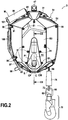
- the fall arrest device D shown in the figures is of the automatic return type. For the sake of brevity, it will hereinafter be referred to simply as "device D".
- the device D comprises a housing B.
- the housing B surrounds all the moving parts of the device D, which protects them against the external environment (dust, dirt, etc.) while protecting the user against contact with these. same parts of the device, and in particular contact with his fingers.
- the housing B mainly consists of two half-shells B1 and B2 fixed to one another so as to define an internal volume of the housing receiving the moving parts of the device D.
- the half-shell B2 furthermore carries a cover B3 which carries the control member C and masks the drive means described below.
- the half-shells B1 and B2 and the cover B3 can be produced by injection molding of a thermoplastic polymer, for example by injection molding of acrylonitrile butadiene styrene (ABS).
- ABS acrylonitrile butadiene styrene
- the half-shells B1 and B2 and the cover B3 are fixed to an internal bracket U described below, for example using screws 91.
- Box B can carry a handle 88 (visible on the figure 1 ), and / or at least one (two in the example shown) shackles 94, and / or a swivel 47.
- the handle 88 can allow the device D to be transported using only one hand.
- the shackle or shackles 94 can make it possible to fix the housing B to a frame A (described below).
- the swivel 47 can make it possible to fix the housing B to the frame A described below or to an anchoring point (not illustrated).
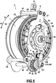
- the figures 5 and 6 show in perspective the device D, the housing B having been removed.
- the internal caliper U comprises a first plate U1 and a second plate U2 integral with one another so as to face each other.
- the plates U1 and U2 are joined together by two rods U8 at their end adjacent to the swivel 48, and by two other rods U9 at their end opposite to the swivel 48, the rods U8 and U9 being fixed to the plates U1 and U2, for example using nuts (not referenced but visible on the figures 5 and 6 ).
- the rods U8 have a cylindrical section, and are spaced so as to be able to receive between them one end of the swivel 47 so that the swivel is free to rotate while being held in position between the rods U8.
- An elastomeric seal U11 for example made of a synthetic rubber such as EPDM, can be provided on the first plate U1 to ensure a seal between the cover B3 and the plate U1 and thus protect the moving parts of the device. D against the external environment.
- the device D further comprises a reel 1.
- the reel 1 is rotatably mounted relative to the housing B, so as to be able to be driven in rotation in a winding direction E + and in an unwinding direction E-.
- the reel 1 can be carried, via bearings (not referenced), by a rotation shaft 29 itself carried by the plates U1 and U2.
- the reel 1 is of the drum type.
- a lanyard 64 can be wound around the reel 1.
- the term “lanyard” is understood to denote a strap, a cable, a chain or a cord, or more generally any flexible element and having sufficient mechanical strength to. join two elements.
- the lanyard 64 can for example wrap around a central portion 1B of the reel 1. Naturally, one end of the lanyard 64 is fixed to the reel 1, for example to its central portion 1B, while one end of the lanyard 64 is attached to the reel 1, for example to its central portion 1B. other end of the lanyard 64 is free.
- a rotation of the reel 1 in the winding direction E + tends to wrap the lanyard 64 around the reel 1 and therefore to distribute a shorter length of lanyard 64 outside the housing B
- a rotation of the reel 1 in the unwinding direction E - tends to unwind the lanyard 64 and therefore to distribute a greater length of lanyard 64 outside the housing B.
- the central portion 1B may have grooves 1BR complementary to the lanyard 64.
- the free end of the lanyard 64 can be provided, as shown in the figures 1 and 2 , a hook 70 allowing the attachment of this free end to personal protective equipment (not shown), such as a harness or a harness, of a user.
- the hook 70 can be connected to the free end of the lanyard 64 via a pivot 69 and two stitches 66, 73.
- a handle 74 can be provided between the free end of the lanyard 64 and the stitches 73, 66 to facilitate the handling of the lanyard 64 by the user.
- the device D comprises an automatic recall means.
- this automatic return means is in the form of a leaf spring 14 (visible in the sectional view of the figure 3A ) received in a groove 1A (visible on the figures 5 and 6 ) corresponding that presents the reel 1.
- This automatic return means is configured to recall the reel 1 in rotation in the winding direction E +. Due to this action of the automatic return means on the reel 1, the lanyard 64 is permanently maintained in tension when the user is attached to the free end of the lanyard 64 via his personal protective equipment. It is however specified that this automatic return means can be omitted from the device D, that is to say that the device D is not necessarily of the automatic return type.
- the device D also comprises an automatic blocking means configured to block the rotation of the reel 1 in the unwinding direction E - in the event of a fall.
- This automatic locking means consists of a pawl 40 pivotally mounted on the plate U1 via a pivot 34 and returned by an elastic element, in this case a torsion spring 39, and a ratchet 83. These elements are better visible on the figure 5 .
- the pawl 40 engages against one of the teeth of the ratchet 83, which blocks the rotation of the reel 1.
- Such an automatic locking means is known as such in the field of fall arrest devices and is therefore not described in more detail here.
- the device D further comprises a drive means.
- This drive means makes it possible to drive the reel 1 at least in the winding direction E +. It comprises a drive shaft 48 rotatably mounted relative to the housing B.
- the drive shaft 48 is carried by the plates U1 and U2, respectively via a ball bearing 53 and via a circlip 41 attached to one end 48A of the drive shaft 48, this end 48A having a shoulder for receive the circlip 41.
- the axis of the drive shaft 48 is preferably coplanar with the axis of the rotation shaft 29.
- the drive shaft 48 may carry a toothed wheel 55 meshing with the teeth. of a toothed part 1D which the reel 1 presents.
- the plane of the axis of the drive shaft 48 and of the axis of the rotation shaft 29 is preferably parallel with the plates U1 and U2, the plates U1 and U2 being themselves parallel, as shown in the figures.
- the drive shaft 48 can be arranged differently with respect to the rotation shaft 29, without departing from the scope of the present disclosure, as long as the drive shaft 48 can rotate the reel. 1 and be rotated by the reel 1.
- the drive shaft 48 can rotate the reel 1 and be rotated by the reel 1 in any other known way, for example via a drive with shaft and flange or with shaft and drive screw.
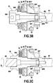
- the drive means is shown in more detail on the figures 3A , 3B and 4 , the figure 3A being a partial sectional view of the figure 2 according to III-III, the figure 3B being an enlargement of part of the partial sectional view of the figure 3A , and the figure 4 being a partially exploded view of device D without housing B.
- the drive means comprises a ratchet 57 which can be driven by the drive shaft 48, and a pawl 44.
- the drive shaft 48 has a portion of larger diameter 48H, this portion of larger diameter 48H having at least two shoulders, one of which keeps the cage of the pump in place.
- ball bearing 53 as shown in figure 3A .
- This portion of larger diameter also has a hollow portion carrying an internal thread 48F complementary to an external thread 50F carried by one end of an actuating portion 50.
- the actuating portion 50 has, at its end opposite to the end carrying the external thread 50F, an indentation 508.
- the indentation 508 is complementary to a tip 98 of a crank M which will be described in more detail later. .
- An end surface 48H1 of the larger diameter portion 48H is in contact with a friction plate 49 ', which itself is in contact with one face of the ratchet 57.
- the other face of the ratchet 57 is in contact. of another friction plate 49, which is itself in contact with a drive portion 52.
- the drive portion 52 is in the form of an annular plate, the central orifice of which is provided with two contact surfaces 52J1, 52J2 which are complementary to two corresponding surfaces 50J1, 50J2 carried by the actuating portion 50, as shown in figure 4 .
- One or more elastic elements are provided between the actuating portion 50 and the drive portion 52.
- these elastic elements are a plurality of (in this case, three) spring washers 51.
- the spring washers 51 are themselves held in place by a shoulder 50A presented by the actuating portion 50.
- the actuating portion 50 is itself held in place in an internal flare of the cover B3 by a washer 50 '.
- the ratchet 57 is mounted on the actuating portion 50 through a washer 56, so that as long as the pawl 44 is disengaged from the ratchet 57, the ratchet 57 can rotate the actuating portion 50 and 'drive shaft 48, and vice versa.
- the pawl 44 is configured to move between a first position in which it does not interfere with the ratchet 57, and a second position in which it interferes with the ratchet 57.
- the pawl 44 is pivotally mounted by with respect to the housing B. More precisely, the pawl 44 is mounted on a pivot 43 which is received in a through hole 42A of a fixing plate 42 attached to the plate U1. The pivot 43 is received in a through hole 441 provided by the pawl 44. A circlip 43 '(visible on the figure 4 ) is received in a groove 43G presented by the pivot in order to hold the pawl 44 in place on the pivot 43.
- the device D can further include a first automatic return means configured to return the pawl 44 to the second position.
- this first automatic return means is a torsion spring R1.
- One of the fixing ends R1A of the torsion spring R1 bears on an edge 42T of the fixing plate 42, while the other fixing end R1B of the torsion spring R1 bears on an edge of the pawl 44.
- the torsion spring R1 is held in place between the fixing plate 42 and the pawl 44 by a shoulder 43A carried by the pivot 43.
- the first automatic return means could be configured differently, and in particular be an elastic element other than a torsion spring, as long as it tends to return the pawl 44 to the second position.
- the device D further comprises a control member C mounted on the housing B.
- the control member C is intended to be manipulated by an outside person, in order to cause the pawl to pass between the first position and the second position.
- the control unit C thus presents, as can be seen on the figures 1 to 3A , a handling portion CM accessible from outside the housing B.
- the handling portion CM may have a slight flaring CP, typically of the dimensions and shape of a human thumb, of so that the outside person can move the CM manipulation portion with the thumb.
- control unit C is mounted on the cover B3.
- the handling portion CM is thus accessible from the exterior face of the cover B3.
- the handling portion CM is integral with a control portion C1.
- This control portion C1 acts on the pawl 44, for example by cooperating with a surface of the pawl 44, in order to cause the pawl 44 to pass from the first position to the second position and from the second position to the first position.
- control portion C1 is pivotally mounted relative to the housing. More precisely, as this is best seen on the figures 3 , 4 and 6 , the control portion C1 can itself take the form of a pivot received in an opening (not referenced) of the cache B3. As is best seen on the figure 4 , the control portion C1 has, at its end opposite to the handling portion CM, a tongue C12 received in a corresponding groove 442 presented by the pawl 44.
- the handling portion CM to pivot around the pivot materialized by the control portion C1
- the external person can bring the control portion C1 from a non-actuation position (shown in the figures 1 to 8 ) to an actuation position (described later with reference to the figure 9 ).
- the handling portion CM and the control portion C1 can be produced by injection molding of a thermoplastic polymer, for example by injection molding of acrylonitrile butadiene styrene (ABS). It is preferable that the handling portion CM and the control portion C1 are produced by injection molding of the same thermoplastic polymer as that used to produce the half-shells B1 and B2 and the cover B3.
- ABS acrylonitrile butadiene styrene
- the device D can further include a second automatic return means configured to return the control portion C1 to the non-actuation position.
- this second automatic return means is a torsion spring R2.
- one of the fixing ends R2A of the torsion spring R2 rests on an internal flare B3R that the cover B3 has, while the other fixing end R2B of the torsion spring R2 is received in a groove C1B that has the control portion C1.
- the second automatic return means could be configured differently, and in particular be an elastic element other than a torsion spring, as long as it tends to return the control portion C1 to the non-actuation position.
- control portion C1 can be brought from a non-actuating position to an actuating position.
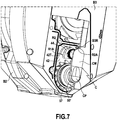
- the figure 8 represents the case where the control portion C1 is in the non-actuation position.
- the control portion C1 is returned to this position by the second automatic return means, that is to say, in the example shown, by the torsion spring R2.
- the pawl 44 is returned to the second position by the first automatic return means, that is to say, in the example shown, by the torsion spring R1; but these first and second automatic return means are configured so that, when the control portion C1 is in the non-actuating position, the second automatic return means impose the position of the control portion C1 on the pawl 44, c ' that is, the pawl 44 is maintained in the first position despite the action of the first automatic return means.
- the stiffness constant of the torsion spring R2 is greater. than the stiffness constant of the torsion spring R1.
- the stiffness constant of the torsion spring R2 can be at least 2 times greater, and preferably between 2 times and 3 times greater than the stiffness constant of the torsion spring R1
- the cavity 508 is masked by the manipulation portion CM when the control portion C1 is in the non-actuating position. In fact, in this case, it is impossible for the external person to incorrectly use the device D by inserting the tip 98 of the crank M into the recess 508 while the pawl 44 is in its first position in which it is not. 'not interfere with ratchet 57.
- the groove 442 of the pawl 42 covers an angular sector larger than the tongue C12 of the control portion C1, in order to create a clearance between the groove 442 and the tongue C12 which allows the pawl 44 to reach its second position when the control portion C1 is brought to the actuation position.
- the end 50B of the actuating portion 50 which carries the external thread 50F receives a 50W deformable washer.
- the deformable washer 50W is provided between the end 50B and the end face of the flare of the drive shaft 48 on which the internal thread 48F is provided. This end face has a blind hole 48J.
- the friction plates 49, 49 ' are kept in contact with the corresponding face of the ratchet 57.
- the friction of the friction plates 49, 49' against the two faces of the ratchet 57 contributes to block the rotation of the ratchet 57, together with the interference of the pawl 44 with the ratchet 57. The reel 1 is thus prevented from driving the ratchet 57.
- any rotation of the crank M after the maximum deformation has been reached drives the actuation portion 50, which in turn drives the drive portion 52 (due to the cooperation between the surfaces 50J1, 50J2 and 52J1, 52J2), the drive shaft 48, and therefore the toothed wheel 55 and finally the reel 1.
- the device D which has just been described offers particularly simple and intuitive operation for the outside person, since it suffices for the latter to manipulate the handling portion CM so that the pawl 44 is brought to the second position and thus allows to the external person to raise the user using the crank M, then to let the control portion C1 be returned to the non-actuating position so that the pawl 44 is again brought to the first position and allows device D to operate as an automatic fall arrester again.
- the ratchet 57 may have an arbitrary number of teeth allowing the pawl 44 to interfere with the ratchet 57.
- the ratchet 57 can be replaced by any element which can be driven by the drive shaft 48, as long as this element materializes an obstacle with which the pawl 44 interferes in the second position and does not interfere in the first position .
- the handling portion CM is received in a flare R that has an outer surface of the housing B.
- the flare R is located on an outer surface of the cover B3.
- the CM manipulation portion can then, as shown in the figure figure 3A , be flush with the outer surface of the cover B3, except possibly at the level of the flaring CP of the handling portion CM. This can prevent, or at least limit, the risk of accidental manipulation of the CM manipulation portion.
- the flare R preferably has two stop portions P1, P2 serving to limit the movement of the handling portion CM in the flare R.
- the handling portion CM abuts against the stop wall P1 when the control portion C1 is in the non-actuating position (position shown in the figure. figure 8 ) and against the stop wall P2 when the control portion C2 is in the actuation position (position shown on the figure 9 ).
- the operation of device D is then considerably more intuitive for the outside person, since it suffices for the latter to bring the handling portion CM against the stop wall P2 when he wishes to use the crank M to raise the user, then to let the second automatic return means bring the handling portion CM back against the stop wall P1.
- the flare R, the handling portion CM and the tip 98 of the crank M are configured such that when the tip 98 is received in the recess 508, the tip 98 maintains the handling portion CM in abutment against the abutment wall P2.
- the operation of the device D is then even more intuitive for the outside person, since it is the very fact of bringing the handling portion CM against the stop wall P2 to introduce the end piece 98 of the crank M which brings the pawl 44 to the second position, then it is the very fact of removing the end piece 98 from the crank M which again brings the handling portion CM into abutment against the stop wall P1 and the pawl 44 in the first position.
- the crank M can in principle have any suitable geometry, as long as it has a tip 98 complementary to the tip 508 and thus allows the outside person to drive the drive shaft 48 in rotation by turning the crank M.
- the M crank has the configuration shown in the figures 1 and 2 .
- the end piece 98 is carried by a first portion 97, which is planar and is integral with a second portion 100, which is also planar and forms an obtuse angle with the first portion 97.
- the first portion planar 97 and the second planar portion 100 can for example be produced by casting or by machining a metal alloy, for example galvanized steel.
- the second planar portion 100 has at one of its ends a rivet 101, with the aid of which a handle 99 is fixed to the second planar portion 100. By manipulating the handle 99, the user can turn the crank M so rotating the drive shaft 48.
- the housing B preferably carries at least one holding element configured to hold the crank M in place on the housing B.
- the half-shell B1 which carries several holding elements, which are in the form of pairs of elastic clips 96, made of a thermoplastic, for example polycarbonate (PC). It is however specified that other types of retaining elements are possible and that all or some of these retaining elements could be placed on the housing B elsewhere than on the half-shell B1.
- the obtuse angle formed by the first planar portion 97 and the second planar portion 100 can be chosen so as to be substantially equal to an angle formed by an outer surface of the housing B, so that the first planar portion 97 and the second planar portion 100 substantially follow the outer curvature of the housing. This makes it possible to transport the crank M together with the device B in a compact manner.
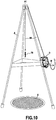
- This fall protection device comprises the fall protection system comprising the device D and the crank M, the lanyard 64 described above and wound around the reel 1 of the device, and a frame A.
- the armature A is a tripod intended to be placed above a pipe manhole E.
- the device D is fixed to the frame A, for example using a carabiner.
- the lanyard 64 is unwound partially outside the device D and passes through a top A1 of the frame A, so that the user can go down and up in the manhole E while being held by the lanyard 64, after having hooked his personal protective equipment on the hook 70.
- the frame A can be of any type known in the field of fall protection, as long as it offers an anchoring point for the device D which is sufficiently robust to protect the user of the device D against falling. and to allow an outside person to reassemble the user.
- fall protection device described can be used to protect the user in any confined space other than a manhole, for example a chimney or a service duct of a building.
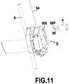
- the fall protection device comprises a source of mechanical power P that can be used in place of the crank M.
- the source of mechanical power P thus comprises a shaft 98 'having a tip 98P complementary to the cavity 508.
- the mechanical power source P can be of any suitable type; it may in particular be an electric motor, possibly powered by a battery.
- device D in this variant is identical to that described in relation to the figures 1 to 10 , except that instead of inserting the tip 98 of the crank M in the recess 508, the external person can introduce the tip 98P into the recess 508. Then, the external person can operate the source. mechanical power P to reassemble the user. The user's ascent does not therefore call on the physical force of the external person, which makes the use of the fall protection device more convenient.
Landscapes
- Health & Medical Sciences (AREA)
- General Health & Medical Sciences (AREA)
- Business, Economics & Management (AREA)
- Emergency Management (AREA)
- Emergency Lowering Means (AREA)
Applications Claiming Priority (1)
| Application Number | Priority Date | Filing Date | Title |
|---|---|---|---|
| FR1910722A FR3101253B1 (fr) | 2019-09-27 | 2019-09-27 | Dispositif antichute, de préférence à rappel automatique |
Publications (1)
| Publication Number | Publication Date |
|---|---|
| EP3797836A1 true EP3797836A1 (de) | 2021-03-31 |
Family
ID=68987975
Family Applications (1)
| Application Number | Title | Priority Date | Filing Date |
|---|---|---|---|
| EP20197085.2A Withdrawn EP3797836A1 (de) | 2019-09-27 | 2020-09-21 | Absturzsicherung, vorzugsweise mit automatischer rückstellung |
Country Status (2)
| Country | Link |
|---|---|
| EP (1) | EP3797836A1 (de) |
| FR (1) | FR3101253B1 (de) |
Cited By (1)
| Publication number | Priority date | Publication date | Assignee | Title |
|---|---|---|---|---|
| CN113856085A (zh) * | 2021-11-03 | 2021-12-31 | 东方电子股份有限公司 | 一种具有逆向锁止机构的电力铁塔高空作业用速差防坠器 |
Citations (3)
| Publication number | Priority date | Publication date | Assignee | Title |
|---|---|---|---|---|
| US1124938A (en) * | 1912-04-17 | 1915-01-12 | Simplex Self Hoisting Machine Company | Hoisting device. |
| US4489919A (en) * | 1983-03-21 | 1984-12-25 | Meyer Ostrobrod | Safety winch with disengageable drive |
| US20080035423A1 (en) * | 2006-08-08 | 2008-02-14 | D B Industries, Inc. | Retractable horizontal lifeline assembly |
-
2019
- 2019-09-27 FR FR1910722A patent/FR3101253B1/fr active Active
-
2020
- 2020-09-21 EP EP20197085.2A patent/EP3797836A1/de not_active Withdrawn
Patent Citations (3)
| Publication number | Priority date | Publication date | Assignee | Title |
|---|---|---|---|---|
| US1124938A (en) * | 1912-04-17 | 1915-01-12 | Simplex Self Hoisting Machine Company | Hoisting device. |
| US4489919A (en) * | 1983-03-21 | 1984-12-25 | Meyer Ostrobrod | Safety winch with disengageable drive |
| US20080035423A1 (en) * | 2006-08-08 | 2008-02-14 | D B Industries, Inc. | Retractable horizontal lifeline assembly |
Cited By (1)
| Publication number | Priority date | Publication date | Assignee | Title |
|---|---|---|---|---|
| CN113856085A (zh) * | 2021-11-03 | 2021-12-31 | 东方电子股份有限公司 | 一种具有逆向锁止机构的电力铁塔高空作业用速差防坠器 |
Also Published As
| Publication number | Publication date |
|---|---|
| FR3101253A1 (fr) | 2021-04-02 |
| FR3101253B1 (fr) | 2022-12-02 |
Similar Documents
| Publication | Publication Date | Title |
|---|---|---|
| EP2637747B1 (de) | Sicherheitsbefestigungsvorrichtung und sicherungsanordnung mit einer solchen vorrichtung | |
| EP0859648B1 (de) | Automatisches fallschutzgerät für grosse höhenarbeit | |
| EP1486294A1 (de) | Verlängerungsstiel zum Betätigen eines Handwerkzeugs | |
| FR2998182A1 (fr) | Appareil de securite sur corde a verrouillage sous charge | |
| FR2748078A1 (fr) | Poulie a flasque pivotant et a bloqueur integre | |
| FR2694203A1 (fr) | Mousqueton à galet de verrouillage automatique. | |
| EP0752255A1 (de) | Bewegliches Absturzsicherungsgerät für flexibles Rettungsseil | |
| EP3797836A1 (de) | Absturzsicherung, vorzugsweise mit automatischer rückstellung | |
| EP0255788A1 (de) | Sicherheitsgurtaufroller | |
| EP0089879B1 (de) | Schnellsperrender und -entsperrender geräuscharmer Sicherheitsgurtaufroller | |
| FR2715965A1 (fr) | Dispositif de sécurité contre la chute, en particulier pour portes basculantes. | |
| FR3042718A1 (fr) | Dispositif antichute a rappel automatique | |
| FR2461146A1 (fr) | Mousqueton a verrouillage automatique | |
| EP1589184B1 (de) | Rolladen mit einer Axialblockiereinrichtung einer in einen Stützflansch hineinandergreifenden Achsensektion | |
| FR2740765A1 (fr) | Mecanisme de traction a cabestan et outillages ainsi equipes | |
| FR2813299A1 (fr) | Treuil pour une roue de secours d'un vehicule | |
| EP1571287A1 (de) | Rolladen zum Schutz einer Öffnung, insbesondere eines Fensters, einer Tür oder dergleichen | |
| FR2754719A1 (fr) | Dispositif de securite pour ouvrier travaillant dans des endroits eleves | |
| EP1446196B1 (de) | Vorrichtung zum lösen der befestigung eines zubehörteils wie einer sauerstoffmaske an einem helm | |
| FR2793837A1 (fr) | Dispositif de securite anti-chute pour fermeture a effacement vertical | |
| FR3057170A1 (fr) | Dispositif antichute a frein d'enroulement | |
| FR2897096A1 (fr) | Boite a ressort de dispositif antichute de rideau roulant a deplacement vertical. | |
| EP1764467B1 (de) | Kastenausgang, insbesondere zur Unterstützung einer Antriebskurbel eines Rollladens und eine mit einem derartigen Kastenausgang versehene Antriebsvorrichtung | |
| EP4039937A1 (de) | Vorrichtung zum aufrollen eines markisentuchs | |
| EP1106776A1 (de) | Gurtroller, Betätigungsvorrichtung für einen Rolladen oder Rollo mit einem derartigen Gurtroller und Vefahren zur Einstellung der Federspannung dieses Gurtrollers |
Legal Events
| Date | Code | Title | Description |
|---|---|---|---|
| PUAI | Public reference made under article 153(3) epc to a published international application that has entered the european phase |
Free format text: ORIGINAL CODE: 0009012 |
|
| STAA | Information on the status of an ep patent application or granted ep patent |
Free format text: STATUS: THE APPLICATION HAS BEEN PUBLISHED |
|
| AK | Designated contracting states |
Kind code of ref document: A1 Designated state(s): AL AT BE BG CH CY CZ DE DK EE ES FI FR GB GR HR HU IE IS IT LI LT LU LV MC MK MT NL NO PL PT RO RS SE SI SK SM TR |
|
| AX | Request for extension of the european patent |
Extension state: BA ME |
|
| STAA | Information on the status of an ep patent application or granted ep patent |
Free format text: STATUS: REQUEST FOR EXAMINATION WAS MADE |
|
| 17P | Request for examination filed |
Effective date: 20210903 |
|
| RBV | Designated contracting states (corrected) |
Designated state(s): AL AT BE BG CH CY CZ DE DK EE ES FI FR GB GR HR HU IE IS IT LI LT LU LV MC MK MT NL NO PL PT RO RS SE SI SK SM TR |
|
| P01 | Opt-out of the competence of the unified patent court (upc) registered |
Effective date: 20230513 |
|
| P02 | Opt-out of the competence of the unified patent court (upc) changed |
Effective date: 20230517 |
|
| GRAP | Despatch of communication of intention to grant a patent |
Free format text: ORIGINAL CODE: EPIDOSNIGR1 |
|
| STAA | Information on the status of an ep patent application or granted ep patent |
Free format text: STATUS: GRANT OF PATENT IS INTENDED |
|
| INTG | Intention to grant announced |
Effective date: 20250310 |
|
| STAA | Information on the status of an ep patent application or granted ep patent |
Free format text: STATUS: THE APPLICATION IS DEEMED TO BE WITHDRAWN |
|
| 18D | Application deemed to be withdrawn |
Effective date: 20250711 |