EP3798403A1 - Dormant en acier profilé - Google Patents
Dormant en acier profilé Download PDFInfo
- Publication number
- EP3798403A1 EP3798403A1 EP20194914.6A EP20194914A EP3798403A1 EP 3798403 A1 EP3798403 A1 EP 3798403A1 EP 20194914 A EP20194914 A EP 20194914A EP 3798403 A1 EP3798403 A1 EP 3798403A1
- Authority
- EP
- European Patent Office
- Prior art keywords
- section
- steel frame
- bar
- profiled steel
- tab
- Prior art date
- Legal status (The legal status is an assumption and is not a legal conclusion. Google has not performed a legal analysis and makes no representation as to the accuracy of the status listed.)
- Granted
Links
Images


Classifications
-
- E—FIXED CONSTRUCTIONS
- E06—DOORS, WINDOWS, SHUTTERS, OR ROLLER BLINDS IN GENERAL; LADDERS
- E06B—FIXED OR MOVABLE CLOSURES FOR OPENINGS IN BUILDINGS, VEHICLES, FENCES OR LIKE ENCLOSURES IN GENERAL, e.g. DOORS, WINDOWS, BLINDS, GATES
- E06B3/00—Window sashes, door leaves, or like elements for closing wall or like openings; Layout of fixed or moving closures, e.g. windows in wall or like openings; Features of rigidly-mounted outer frames relating to the mounting of wing frames
- E06B3/96—Corner joints or edge joints for windows, doors, or the like frames or wings
- E06B3/964—Corner joints or edge joints for windows, doors, or the like frames or wings using separate connection pieces, e.g. T-connection pieces
- E06B3/968—Corner joints or edge joints for windows, doors, or the like frames or wings using separate connection pieces, e.g. T-connection pieces characterised by the way the connecting pieces are fixed in or on the frame members
-
- E—FIXED CONSTRUCTIONS
- E06—DOORS, WINDOWS, SHUTTERS, OR ROLLER BLINDS IN GENERAL; LADDERS
- E06B—FIXED OR MOVABLE CLOSURES FOR OPENINGS IN BUILDINGS, VEHICLES, FENCES OR LIKE ENCLOSURES IN GENERAL, e.g. DOORS, WINDOWS, BLINDS, GATES
- E06B1/00—Border constructions of openings in walls, floors, or ceilings; Frames to be rigidly mounted in such openings
- E06B1/04—Frames for doors, windows, or the like to be fixed in openings
- E06B1/12—Metal frames
- E06B1/14—Metal frames of special cross-section not used
- E06B1/16—Hollow frames
-
- E—FIXED CONSTRUCTIONS
- E06—DOORS, WINDOWS, SHUTTERS, OR ROLLER BLINDS IN GENERAL; LADDERS
- E06B—FIXED OR MOVABLE CLOSURES FOR OPENINGS IN BUILDINGS, VEHICLES, FENCES OR LIKE ENCLOSURES IN GENERAL, e.g. DOORS, WINDOWS, BLINDS, GATES
- E06B3/00—Window sashes, door leaves, or like elements for closing wall or like openings; Layout of fixed or moving closures, e.g. windows in wall or like openings; Features of rigidly-mounted outer frames relating to the mounting of wing frames
- E06B3/96—Corner joints or edge joints for windows, doors, or the like frames or wings
- E06B3/964—Corner joints or edge joints for windows, doors, or the like frames or wings using separate connection pieces, e.g. T-connection pieces
- E06B3/968—Corner joints or edge joints for windows, doors, or the like frames or wings using separate connection pieces, e.g. T-connection pieces characterised by the way the connecting pieces are fixed in or on the frame members
- E06B3/9687—Corner joints or edge joints for windows, doors, or the like frames or wings using separate connection pieces, e.g. T-connection pieces characterised by the way the connecting pieces are fixed in or on the frame members with screws blocking the connecting piece inside or on the frame member
- E06B3/9688—Mitre joints
Definitions
- the invention relates to a profiled steel frame with a laterally arranged hinge rod and a laterally arranged lock bar as well as a head bar connecting the hinge bar to the lock bar.
- the ribbon rod, the lock rod and the head rod are formed from a steel profile.
- the head bar rests against one another with the band bar and / or the lock bar in a corner area with a miter cut.
- Door frames are used to enclose a building opening which can be closed by means of a door leaf.
- a frame has two lateral bars, which are arranged laterally next to the doorway in a lateral direction and aligned in a vertical direction, and which are also referred to as a hinge rod and a lock rod.
- the hinge rod is formed by that side rail on the side of which the door leaf is attached to the frame or a wall surrounding the wall opening by means of door hinges.
- the opposite spar is also referred to as the lock rod, with door locks and / or latches usually located on this side.
- the crossbeam which connects the two side rails and is arranged in the vertical direction above the doorway is also referred to as the head bar.
- a door leaf that closes the doorway rests on three sides against the hinge rod, the head rod and the lock rod.
- the door frame and / or the door leaf can be designed with a rebate at which they interlock in stages.
- the invention is nonetheless also suitable for butt-hinged doors.
- Particularly robust and resistant door frames are formed from metal profiles, in particular from sheet steel. These have a high temperature resistance and are themselves non-flammable. Steel frames in connection with door leaves from a filled or unfilled sheet metal box are therefore often used as security doors or as fire doors.
- corresponding endless profiles are produced - for example by edging a sheet metal strip - and then cut to the required length for the hinge rod, lock rod and head rod.
- the profiles have an identical cross-section so that they can be set against one another with a 45 degree miter cut.
- the steel profile has at least one mirror section and one passage section. Furthermore, areas can be formed which serve to form or receive a fold and / or to receive seals and functional elements. This allows the metal profiles to take on complex shapes to form a steel frame.
- the invention is based on the object of improving the connection in the corner area between the head bar on the one hand and the hinge bar or the lock bar on the other hand in a profiled steel frame.
- the connection should be established with little expenditure of time and money and should ensure high stability and secure alignment of the metal profiles.
- the head bar is connected to the hinge bar and / or the lock bar by an angled shoe attached to the end of the respective steel profile.
- the at least one angle shoe extends into at least one end of the head rod and into one end of the ribbon rod or the lock rod.
- the angle shoe is shaped in such a way that it rests positively on an inside of the steel profile forming the head bar and on the other hand positively on an inside of the further steel profile that forms the hinge bar or the lock bar.
- the shape of the angle shoe is designed in such a way that the desired angled arrangement between the steel profiles is ensured through correct insertion and fastening.
- the angle shoe is attached directly to both steel profiles, so that direct welding of the two steel profiles to one another is not necessary. Is within the scope of the invention It is possible to avoid an expensive weld seam between the heavily profiled steel parts and to replace it with an additional part through a robust and reliable indirect connection.
- the profiled steel frame is particularly preferably designed as a block frame.
- Block frames are located completely within a doorway and do not protrude beyond this in the lateral direction, the vertical direction and in either direction perpendicular to the doorway. They are therefore particularly easy to assemble compared to surrounding frames. As a result, the individual profiles of the frame can be completely assembled in advance. For assembly, they are simply pushed into the doorway in the direction of passage and fixed there.
- the angle shoe is particularly preferably screwed to the steel profiles.
- a screw connection has the advantage that it can also be produced directly on site during installation without complex additional equipment such as welding equipment.
- a steel frame according to the invention can thus be provided as a kit in a particularly space-saving manner.
- This comprises at least one angle shoe as well as a head rod, a band rod and / or a lock rod forming steel profiles.
- these and / or the angle shoe can be designed or pre-drilled with through holes.
- Screws in particular self-tapping self-tapping screws, can be screwed into this for fastening.
- the screws are particularly preferably designed as flat head screws which are screwed into the metal profiles and the angle shoe on the outside.
- the head of the flat head screw has a maximum height of 2 mm, preferably a maximum of 1 mm so that the screw heads can be accommodated in the assembly gap between the door frame and the wall.
- the angle shoe is formed from a single piece of sheet metal, in particular sheet steel.
- Sheet metal is a durable and at the same time inexpensive material. This can be processed with the same machines as the sheet metal strips for producing the steel profiles for the steel frame. In particular, a workpiece with high intrinsic stability can be produced by edging a sheet metal.
- the angled shoe particularly preferably has a first angular section and a second angular section bent at right angles thereto.
- the first angle section is followed by a first tab, which is bent at right angles with respect to the first angle section.
- the first tab also extends at right angles to the second angular section.
- the first tab is - directly or indirectly - connected, preferably welded, to the second angular section.
- the first bracket fixes and stabilizes the first angular section and the second angular section in their position bent by 90 degrees relative to one another.
- the angle shoe is thus suitable for giving the steel frame the necessary stability in the corner area and for ensuring reliable alignment of the head bar with respect to the hinge bar or the lock bar.
- a second bracket adjoins the second angular section, which tab is bent at right angles with respect to the second angular section.
- the first flap and the second flap run flush with one another, that is to say in one plane.
- the second tab is with the first tab connected, preferably welded.
- the first tab and the second tab abut one another with two mutually facing end faces, whereupon the connection is established.
- the first tab and the second tab each have a miter cut with which they rest against one another.
- the miter cut of the flat tabs can be welded more easily and reliably than the profiled frame elements.
- both the first tab and the second tab can be designed to be essentially rectangular in order to simplify the manufacturing process and to reduce costs.
- the first tab extends on the first angular section right up to the fold to which the second angular section adjoins.
- the first flap is then attached directly to the second angular section with one end edge.
- the second flap does not extend directly to the fold, but ends in front of it at a distance which corresponds to the width of the first flap.
- the folded second tab is then attached with its end face to a longitudinal edge of the first tab facing away from the first angular section. The production of a miter cut can be avoided here.
- a form-fit connection is preferably formed in the connection area between the first tab and the second tab.
- a form-locking projection is formed on the first tab or the second tab, which positively engages in an associated form-locking receptacle of the second tabs or the first tab.
- the form-fit connection is designed, in particular, for tensile stress in order to prevent the first tab and the second tab from being pulled apart - and thus preventing the angle shoe from bending open.
- compressive forces can also be transmitted by the first tab being flush with the second tab.
- the form-fit connection at least supports the cohesion between the first tab and the second tab.
- the connection of the tabs can be formed exclusively by the form fit - with the omission of a welded connection. This enables a particularly flat and level construction without a raised weld seam.
- the steel profile (of the head bar, the hinge bar and / or the lock bar) preferably has a door-side mirror section, an adjoining passage section facing the doorway, and an adjoining mutual mirror section.
- the angled shoe lies flat with the first tab and / or possibly the second tab on an inside of the door-side mirror section or the mutual mirror section. In this way, a large-area support can be achieved, which contributes to the stability of the steel frame.
- tabs are arranged on both sides of the first angle section and / or on the second angle section in the passage direction, which are flat both on the inside of the door-side mirror section and on the inside of the mutual mirror section rest.
- the angle shoe is thus held positively in the passage direction in the door profile and can transmit forces on both sides through support.
- the steel profile (of the head bar, the hinge bar and / or the lock bar) preferably has a first fastening section adjoining the door-side mirror section and bent over in the direction of the mutual mirror section and / or a second fastening section adjoining the mutual mirror section and bent over in the direction of the door-side mirror section on.
- the angle shoe with the first angle section rests flat against the inside of the first fastening section and / or the second fastening section.
- the angle shoe thus fills the corner area of the steel frame with a positive fit and can optimally transfer forces.
- a trim profile can also be attached to the first attachment section and the second attachment section, which is arranged on a side of the steel frame facing away from the doorway and increases its insertion width or height.
- the first fastening section and the second fastening section expediently run in one plane. According to a preferred embodiment, they are not connected to one another and in particular have a spacing.
- the interior of the frame profile is accessible from the outside facing away from the doorway. This makes it easier to insert and correctly position the angled shoe.
- the angle shoe bridges the distance between the first fastening section and the second fastening section, as a result of which the steel profile is additionally stabilized.
- the angle shoe is connected to the steel profiles (of the head bar and the lock bar or the ribbon bar) exclusively at the first fastening section and / or at the second fastening section.
- a screw connection is preferably provided for the connection, which can also be released again later.
- the Fig. 1 shows in an oblique perspective a wall surface 1 with a wall opening 2 arranged therein, which is surrounded by a profiled steel frame 3 according to the invention.
- the wall surface 1 extends substantially in a lateral direction x and a height direction y.
- a passage through the wall opening 2 is possible in a passage direction z.
- the steel frame 3 has a hinge rod 3 a arranged to the side of the wall opening 2 in the lateral direction x and a lock rod 3 b arranged opposite it.
- a door leaf 4 is hinged on the hinge rod 3a by means of door hinges so as to be pivotable about a pivot axis running in the vertical direction y.
- the door leaf 4 is located behind the wall surface 1 in the illustration, so that it is only indicated by dashed lines.
- a head bar 3c connecting the hinge bar 3a to the lock bar 3b is arranged.
- the hinge rod 3a, the lock rod 3b and the head rod 3c are formed from a steel profile.
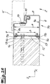
- the Figure 2A shows one example in the Fig. 1 indicated horizontal section through the lock rod 3b.
- the profile of the head rod 3c and of the ribbon rod 3a are therefore essentially identical and only differ in their alignment.
- the head rod 3c rests both with the hinge rod 3a and with the lock rod 3b in a corner area 5 with a miter cut 6.
- the head rod 3c is connected to the lock rod 3b by an angle shoe 7 pushed into the steel profile of the head rod 3c and the steel profile of the lock rod 3b and fixed to the profiles of the head rod 3c and the lock rod 3b is.
- an angle shoe 7 pushed into the steel profile of the head rod 3c and the steel profile of the lock rod 3b and fixed to the profiles of the head rod 3c and the lock rod 3b is.
- the profiled shape of the frame profile is in Figure 2A shown by way of example using the lock rod 3b.
- the steel profile has a door-side mirror section 8a, a passage section 8b and an adjoining mutual mirror section 8c.
- the steel frame 3 is clearly designed as a block frame which is arranged exclusively within the wall opening 2 enclosed by the wall 1.
- the two mirror sections 8a, 8c are aligned with the outer surfaces of the wall 1.
- the steel profile of the lock rod 3b has a cavity with an inner width a measured in the passage direction z between an inner surface 9a of the door-side mirror section 8a and an opposite inner side 9b of the mutual mirror section 8c .
- the outer contour of the door leaf 4 ' is indicated in the closed state.
- the variant shown is a so-called thin rebate door, as is often found in the area of steel doors.
- a thin projection referred to as a fold extends to the outside of the mirror section 8a.
- the main body of the door leaf 4 ′ which is widened in comparison, is essentially received in a stepped recess of the through section 8b.
- the passage section 8b also has a groove for fastening a door seal 10.
- a first fastening section 11a directly adjoining the door-side mirror section 8a and a second fastening section 11b directly adjoining the mutual mirror section 8c are also provided.
- the two fastening sections 11a, 11b run in one plane and are at a distance b from one another. Between the two Fastening sections 11a, 11b thus remain an opening through which the inside of the steel frame 3 is accessible in the unassembled state.
- a fastening plate 12 can also be seen, which rests against the inside of the fastening sections 11a, 11b and is connected to them by flat head screws 13.
- the fastening plate 12 is pegged to the wall 1 by means of a retaining screw 14.
- the head of the retaining screw 14 is accessible through an opening in the frame profile 3b that can be closed by means of a cap 15.
- the gap between the frame profile 3b and the wall 1 is closed by means of joint material 16.
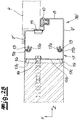
- the Figure 2B shows a corresponding view in an alternative embodiment of the frame profile.
- the modified lock rod 3b ' is constructed in two parts from two interconnected hollow profiles.
- the inner profile corresponds to the lock rod 3b of the embodiment described above.
- This is connected on the outside with a trim profile 17.
- the trim profile 17 is C-shaped with an opening facing the inner profile. This opening is delimited by two S-shaped projections 17a, which engage behind the fastening sections 11a, 11b of the profile on the inside.
- flat head screws 13 are provided for fastening between the two hollow profiles.
- the external dimensions of the block frame formed is increased by the trim profile 17.
- a standardized steel frame can also be used safely and visually appealing in an oversized wall opening 2.
- the outer walls of the facing profile 17 are aligned with the mirror sections 8a ', 8c' of the inside profile.
- the lock rod 3b 'shown is fastened to the wall 1 via a retaining screw 14, which directly through a middle leg 17b of the facing profile 17 facing away from the opening.
- passage openings 17c are also arranged in the central leg 17b.
- the angle shoe 7 used according to the invention is shown separately in a three-dimensional view.
- This has a first angular section 18a and a second angular section 18b directly adjoining this and bent at right angles.
- a first bracket 19a adjoins the first angular section 18a and is bent at right angles with respect to the first angular section 18a.
- a second bracket 19b adjoins the second angular section 18b, which is bent at right angles with respect to the second angular section 18b.
- the first tab 19a and the second tab 19b run in one plane and are welded to one another along a miter seam 20.
- the first bracket 19a is indirectly connected to the second angular section 18b by the miter seam 20.
- the angle shoe 7 is designed to be mirror-symmetrical with respect to a center plane running in the transverse direction x and the height direction y.
- first angular section 18a and the second angular section 18b opposite the first tab 19a or the second tab 19b in the passage direction z identically designed further tabs 19a ', 19b' are arranged which, as it were, are connected to one another by means of a second angular seam 20 ' are connected.
- the outer sides of the first angular section 18a and the second angular section 18b of the angled shoe 7 lie against associated inner surfaces of the fastening sections 11a, 11b of the steel profiles 3a, 3b, 3c.
- two elongated holes 22 each extending in the transverse direction x and the height direction y are provided both on the first angular section 18a and on the second angular section 18b. These serve to accommodate retaining screws 14 for fixing the steel frame 3 on the wall 1.
- the elongated holes 22 are arranged asymmetrically with respect to the longitudinal center plane.
- FIG. 4 is a cross-section through the corner area of an assembled steel frame according to the invention.
- the angle shoe 7 is pushed into the steel profiles of the head rod 3c and the lock rod 3b at the end and is fastened to them by means of flat head screws 13.
- the sectional view shows how the flat head screws 13 pass through the first fastening section 11a of the two steel profiles and are screwed into the first angle section 18a and the second angle section 18b of the angle shoe 7. These are stabilized by two tabs 19a ', 19b' which are welded to one another with a miter seam 20 '.
- the steel frame 3 is fastened in the corner area 5 by means of two retaining screws 14 which are screwed into the wall material 1.
- the Fig. 5 shows an alternative embodiment of the angle shoe 7 'for forming the profiled steel frame according to the invention.
- This likewise has a first angular section 18a and a second angular section 18b bent at right angles from it.
- a first bracket 19a adjoins the first angle section 18a, which is bent at right angles with respect to the first angle section 18a and also runs at right angles to the second angle section 18b.
- a second bracket 19b adjoins the second angular section 18b, which opposite the second angular section 18b is bent at right angles and runs in the same plane as the first tab 19a.
- the first tab 19a and the second tab 19b are essentially rectangular and are designed without a miter cut.
- the first tab 19a has a recess in which the second tab 19b is arranged.
- the second tab 19b can reach right up to the first angular section 18a.
- the second bracket 19b and the first angular section 19a are not connected to one another. For additional stabilization, however, a weld seam could also be made in this area.
- a form-locking projection 23a is formed on the first tab 19a, which has a web and an adjoining round thickening in the manner of a puzzle connection.
- the second tab 19b has an associated form-fit receptacle 23b with a corresponding internal shape, into which the form-fit projection 23a engages in a form-fitting manner.
- the round thickening is clearly overdimensioned in relation to the web, so that it is not possible to pull the form-fit projection 23a out of the receptacle 23b.
- This form-fit connection 23 can also absorb compressive forces.
- the first tab 19a and the second tab 19b also rest against one another in a form-fitting manner at a joint edge 24.
- FIG. 5 The illustrated embodiment has elongated holes 22 aligned symmetrically with respect to a longitudinal center plane.
- the illustrated angled shoe 7 ' is therefore equally suitable for left-hand as well as right-hand assembly.
- a notch 25 is formed in each of the transition areas between the first angular section 18a and the first tab 19a or between the second angular section 18b and the second tab 19b.
- Fig. 5 illustrated embodiment are in contrast to the variant according to Fig. 3 no pilot holes 21 are provided. Instead, drilling screws are preferably used for assembly, which can screw into the material of the angle shoe 7 '. The independence of any pre-drilled holes 21 enables greater flexibility in assembly and increased precision in alignment.
Landscapes
- Engineering & Computer Science (AREA)
- Civil Engineering (AREA)
- Structural Engineering (AREA)
- Joining Of Corner Units Of Frames Or Wings (AREA)
- Door And Window Frames Mounted To Openings (AREA)
- Rod-Shaped Construction Members (AREA)
- Paper (AREA)
- Securing Of Glass Panes Or The Like (AREA)
Applications Claiming Priority (1)
| Application Number | Priority Date | Filing Date | Title |
|---|---|---|---|
| DE102019124015.8A DE102019124015A1 (de) | 2019-09-06 | 2019-09-06 | Profilierte Stahlzarge |
Publications (2)
| Publication Number | Publication Date |
|---|---|
| EP3798403A1 true EP3798403A1 (fr) | 2021-03-31 |
| EP3798403B1 EP3798403B1 (fr) | 2023-03-22 |
Family
ID=72428182
Family Applications (1)
| Application Number | Title | Priority Date | Filing Date |
|---|---|---|---|
| EP20194914.6A Active EP3798403B1 (fr) | 2019-09-06 | 2020-09-07 | Dormant en acier profilé |
Country Status (5)
| Country | Link |
|---|---|
| EP (1) | EP3798403B1 (fr) |
| DE (1) | DE102019124015A1 (fr) |
| ES (1) | ES2946418T3 (fr) |
| HU (1) | HUE062257T2 (fr) |
| PL (1) | PL3798403T3 (fr) |
Citations (2)
| Publication number | Priority date | Publication date | Assignee | Title |
|---|---|---|---|---|
| WO1984002559A1 (fr) * | 1982-12-29 | 1984-07-05 | Japan Art Kikaku Co Ltd | Dispositif de couplage pour cadre façonne |
| US5671580A (en) * | 1996-01-23 | 1997-09-30 | Chou; Kuo-Hua | Frame assembly |
-
2019
- 2019-09-06 DE DE102019124015.8A patent/DE102019124015A1/de active Pending
-
2020
- 2020-09-07 HU HUE20194914A patent/HUE062257T2/hu unknown
- 2020-09-07 PL PL20194914.6T patent/PL3798403T3/pl unknown
- 2020-09-07 EP EP20194914.6A patent/EP3798403B1/fr active Active
- 2020-09-07 ES ES20194914T patent/ES2946418T3/es active Active
Patent Citations (2)
| Publication number | Priority date | Publication date | Assignee | Title |
|---|---|---|---|---|
| WO1984002559A1 (fr) * | 1982-12-29 | 1984-07-05 | Japan Art Kikaku Co Ltd | Dispositif de couplage pour cadre façonne |
| US5671580A (en) * | 1996-01-23 | 1997-09-30 | Chou; Kuo-Hua | Frame assembly |
Also Published As
| Publication number | Publication date |
|---|---|
| HUE062257T2 (hu) | 2023-10-28 |
| EP3798403B1 (fr) | 2023-03-22 |
| DE102019124015A1 (de) | 2021-03-11 |
| PL3798403T3 (pl) | 2023-07-24 |
| ES2946418T3 (es) | 2023-07-18 |
Similar Documents
| Publication | Publication Date | Title |
|---|---|---|
| EP1152112A2 (fr) | Assemblage charnière-cadre ajustable | |
| DE20003819U1 (de) | Vorrichtung zum Abstützen von Fenster- oder Türrahmen an der Begrenzung einer Wandöffnung | |
| DE3546909C2 (de) | Blend- oder Flügelrahmen für Fenster oder Türen | |
| EP0716210A2 (fr) | Joint d'angle pour profilé en plastic | |
| EP2252751B1 (fr) | Ferrure de tige d entraînement pour une fenêtre ou une porte | |
| EP3112577B1 (fr) | Joint abaissable | |
| EP1159502B1 (fr) | Fenetre ou porte | |
| DE19526207C2 (de) | Stahltürblatt | |
| EP3798403B1 (fr) | Dormant en acier profilé | |
| WO1995028543A1 (fr) | Profile creux de cadre de fenetre et chassis de fenetre a deux battants utilisant ce profile | |
| EP0725202B1 (fr) | Armature pour portes ou fenêtres | |
| DE202019006111U1 (de) | Profilierte Stahlzarge | |
| DE102012218887B4 (de) | Schließstück für ein Fenster, eine Tür oder dergleichen | |
| EP1892361A1 (fr) | Fenêtre ou porte de sécurité anti-effraction | |
| EP2060726B1 (fr) | Profilé creux | |
| EP3626927B1 (fr) | Profilé composite pour fenêtres et/ou portes | |
| EP4446552B1 (fr) | Battant mobile par rapport à un dormant d'une fenêtre ou d'une porte et procédé de fixation de deux profilés principaux | |
| EP4102021B1 (fr) | Profilé de chambre creuse de fenêtre ou de porte, système doté d'un tel profilé de chambre creuse et châssis fabriqué à partir de celui-ci | |
| AT394749B (de) | Verkleidung | |
| EP4407127B1 (fr) | Système de battant coulissant avec verrouillage spécial | |
| EP4345240B1 (fr) | Liaison de profilé en métal léger | |
| EP2270297B1 (fr) | Fermeture de bâtiment réduisant l'effet d'explosion et/ou d'intrusion | |
| DE102020132402B4 (de) | Eckschweißverbinder mit Kappe für Kunststoffhohlprofile, dessen Kombination mit einem Kunststoffhohlprofil und Verfahren zur Herstellung einer Eckschweißverbindung | |
| EP2876240B1 (fr) | Fenêtre ou porte | |
| EP3656955B1 (fr) | Gâche |
Legal Events
| Date | Code | Title | Description |
|---|---|---|---|
| PUAI | Public reference made under article 153(3) epc to a published international application that has entered the european phase |
Free format text: ORIGINAL CODE: 0009012 |
|
| STAA | Information on the status of an ep patent application or granted ep patent |
Free format text: STATUS: THE APPLICATION HAS BEEN PUBLISHED |
|
| AK | Designated contracting states |
Kind code of ref document: A1 Designated state(s): AL AT BE BG CH CY CZ DE DK EE ES FI FR GB GR HR HU IE IS IT LI LT LU LV MC MK MT NL NO PL PT RO RS SE SI SK SM TR |
|
| AX | Request for extension of the european patent |
Extension state: BA ME |
|
| STAA | Information on the status of an ep patent application or granted ep patent |
Free format text: STATUS: REQUEST FOR EXAMINATION WAS MADE |
|
| 17P | Request for examination filed |
Effective date: 20210514 |
|
| RBV | Designated contracting states (corrected) |
Designated state(s): AL AT BE BG CH CY CZ DE DK EE ES FI FR GB GR HR HU IE IS IT LI LT LU LV MC MK MT NL NO PL PT RO RS SE SI SK SM TR |
|
| GRAP | Despatch of communication of intention to grant a patent |
Free format text: ORIGINAL CODE: EPIDOSNIGR1 |
|
| STAA | Information on the status of an ep patent application or granted ep patent |
Free format text: STATUS: GRANT OF PATENT IS INTENDED |
|
| INTG | Intention to grant announced |
Effective date: 20221201 |
|
| GRAS | Grant fee paid |
Free format text: ORIGINAL CODE: EPIDOSNIGR3 |
|
| GRAA | (expected) grant |
Free format text: ORIGINAL CODE: 0009210 |
|
| STAA | Information on the status of an ep patent application or granted ep patent |
Free format text: STATUS: THE PATENT HAS BEEN GRANTED |
|
| AK | Designated contracting states |
Kind code of ref document: B1 Designated state(s): AL AT BE BG CH CY CZ DE DK EE ES FI FR GB GR HR HU IE IS IT LI LT LU LV MC MK MT NL NO PL PT RO RS SE SI SK SM TR |
|
| REG | Reference to a national code |
Ref country code: GB Ref legal event code: FG4D Free format text: NOT ENGLISH |
|
| REG | Reference to a national code |
Ref country code: CH Ref legal event code: EP |
|
| REG | Reference to a national code |
Ref country code: DE Ref legal event code: R096 Ref document number: 502020002789 Country of ref document: DE |
|
| REG | Reference to a national code |
Ref country code: IE Ref legal event code: FG4D Free format text: LANGUAGE OF EP DOCUMENT: GERMAN |
|
| REG | Reference to a national code |
Ref country code: AT Ref legal event code: REF Ref document number: 1555379 Country of ref document: AT Kind code of ref document: T Effective date: 20230415 |
|
| REG | Reference to a national code |
Ref country code: NL Ref legal event code: FP |
|
| REG | Reference to a national code |
Ref country code: SE Ref legal event code: TRGR |
|
| REG | Reference to a national code |
Ref country code: LT Ref legal event code: MG9D |
|
| REG | Reference to a national code |
Ref country code: ES Ref legal event code: FG2A Ref document number: 2946418 Country of ref document: ES Kind code of ref document: T3 Effective date: 20230718 |
|
| PG25 | Lapsed in a contracting state [announced via postgrant information from national office to epo] |
Ref country code: RS Free format text: LAPSE BECAUSE OF FAILURE TO SUBMIT A TRANSLATION OF THE DESCRIPTION OR TO PAY THE FEE WITHIN THE PRESCRIBED TIME-LIMIT Effective date: 20230322 Ref country code: NO Free format text: LAPSE BECAUSE OF FAILURE TO SUBMIT A TRANSLATION OF THE DESCRIPTION OR TO PAY THE FEE WITHIN THE PRESCRIBED TIME-LIMIT Effective date: 20230622 Ref country code: LV Free format text: LAPSE BECAUSE OF FAILURE TO SUBMIT A TRANSLATION OF THE DESCRIPTION OR TO PAY THE FEE WITHIN THE PRESCRIBED TIME-LIMIT Effective date: 20230322 Ref country code: LT Free format text: LAPSE BECAUSE OF FAILURE TO SUBMIT A TRANSLATION OF THE DESCRIPTION OR TO PAY THE FEE WITHIN THE PRESCRIBED TIME-LIMIT Effective date: 20230322 Ref country code: HR Free format text: LAPSE BECAUSE OF FAILURE TO SUBMIT A TRANSLATION OF THE DESCRIPTION OR TO PAY THE FEE WITHIN THE PRESCRIBED TIME-LIMIT Effective date: 20230322 |
|
| PG25 | Lapsed in a contracting state [announced via postgrant information from national office to epo] |
Ref country code: GR Free format text: LAPSE BECAUSE OF FAILURE TO SUBMIT A TRANSLATION OF THE DESCRIPTION OR TO PAY THE FEE WITHIN THE PRESCRIBED TIME-LIMIT Effective date: 20230623 Ref country code: FI Free format text: LAPSE BECAUSE OF FAILURE TO SUBMIT A TRANSLATION OF THE DESCRIPTION OR TO PAY THE FEE WITHIN THE PRESCRIBED TIME-LIMIT Effective date: 20230322 |
|
| REG | Reference to a national code |
Ref country code: HU Ref legal event code: AG4A Ref document number: E062257 Country of ref document: HU |
|
| PG25 | Lapsed in a contracting state [announced via postgrant information from national office to epo] |
Ref country code: SM Free format text: LAPSE BECAUSE OF FAILURE TO SUBMIT A TRANSLATION OF THE DESCRIPTION OR TO PAY THE FEE WITHIN THE PRESCRIBED TIME-LIMIT Effective date: 20230322 Ref country code: RO Free format text: LAPSE BECAUSE OF FAILURE TO SUBMIT A TRANSLATION OF THE DESCRIPTION OR TO PAY THE FEE WITHIN THE PRESCRIBED TIME-LIMIT Effective date: 20230322 Ref country code: PT Free format text: LAPSE BECAUSE OF FAILURE TO SUBMIT A TRANSLATION OF THE DESCRIPTION OR TO PAY THE FEE WITHIN THE PRESCRIBED TIME-LIMIT Effective date: 20230724 Ref country code: EE Free format text: LAPSE BECAUSE OF FAILURE TO SUBMIT A TRANSLATION OF THE DESCRIPTION OR TO PAY THE FEE WITHIN THE PRESCRIBED TIME-LIMIT Effective date: 20230322 |
|
| PG25 | Lapsed in a contracting state [announced via postgrant information from national office to epo] |
Ref country code: SK Free format text: LAPSE BECAUSE OF FAILURE TO SUBMIT A TRANSLATION OF THE DESCRIPTION OR TO PAY THE FEE WITHIN THE PRESCRIBED TIME-LIMIT Effective date: 20230322 Ref country code: IS Free format text: LAPSE BECAUSE OF FAILURE TO SUBMIT A TRANSLATION OF THE DESCRIPTION OR TO PAY THE FEE WITHIN THE PRESCRIBED TIME-LIMIT Effective date: 20230722 |
|
| REG | Reference to a national code |
Ref country code: DE Ref legal event code: R097 Ref document number: 502020002789 Country of ref document: DE |
|
| PLBE | No opposition filed within time limit |
Free format text: ORIGINAL CODE: 0009261 |
|
| STAA | Information on the status of an ep patent application or granted ep patent |
Free format text: STATUS: NO OPPOSITION FILED WITHIN TIME LIMIT |
|
| PG25 | Lapsed in a contracting state [announced via postgrant information from national office to epo] |
Ref country code: SI Free format text: LAPSE BECAUSE OF FAILURE TO SUBMIT A TRANSLATION OF THE DESCRIPTION OR TO PAY THE FEE WITHIN THE PRESCRIBED TIME-LIMIT Effective date: 20230322 Ref country code: DK Free format text: LAPSE BECAUSE OF FAILURE TO SUBMIT A TRANSLATION OF THE DESCRIPTION OR TO PAY THE FEE WITHIN THE PRESCRIBED TIME-LIMIT Effective date: 20230322 |
|
| 26N | No opposition filed |
Effective date: 20240102 |
|
| PG25 | Lapsed in a contracting state [announced via postgrant information from national office to epo] |
Ref country code: LU Free format text: LAPSE BECAUSE OF NON-PAYMENT OF DUE FEES Effective date: 20230907 |
|
| REG | Reference to a national code |
Ref country code: BE Ref legal event code: MM Effective date: 20230930 |
|
| PG25 | Lapsed in a contracting state [announced via postgrant information from national office to epo] |
Ref country code: LU Free format text: LAPSE BECAUSE OF NON-PAYMENT OF DUE FEES Effective date: 20230907 Ref country code: MC Free format text: LAPSE BECAUSE OF FAILURE TO SUBMIT A TRANSLATION OF THE DESCRIPTION OR TO PAY THE FEE WITHIN THE PRESCRIBED TIME-LIMIT Effective date: 20230322 |
|
| REG | Reference to a national code |
Ref country code: IE Ref legal event code: MM4A |
|
| PG25 | Lapsed in a contracting state [announced via postgrant information from national office to epo] |
Ref country code: IE Free format text: LAPSE BECAUSE OF NON-PAYMENT OF DUE FEES Effective date: 20230907 |
|
| PG25 | Lapsed in a contracting state [announced via postgrant information from national office to epo] |
Ref country code: IE Free format text: LAPSE BECAUSE OF NON-PAYMENT OF DUE FEES Effective date: 20230907 |
|
| PG25 | Lapsed in a contracting state [announced via postgrant information from national office to epo] |
Ref country code: BE Free format text: LAPSE BECAUSE OF NON-PAYMENT OF DUE FEES Effective date: 20230930 |
|
| PG25 | Lapsed in a contracting state [announced via postgrant information from national office to epo] |
Ref country code: CY Free format text: LAPSE BECAUSE OF FAILURE TO SUBMIT A TRANSLATION OF THE DESCRIPTION OR TO PAY THE FEE WITHIN THE PRESCRIBED TIME-LIMIT; INVALID AB INITIO Effective date: 20200907 |
|
| REG | Reference to a national code |
Ref country code: CH Ref legal event code: U11 Free format text: ST27 STATUS EVENT CODE: U-0-0-U10-U11 (AS PROVIDED BY THE NATIONAL OFFICE) Effective date: 20251001 |
|
| PGFP | Annual fee paid to national office [announced via postgrant information from national office to epo] |
Ref country code: DE Payment date: 20250911 Year of fee payment: 6 |
|
| PGFP | Annual fee paid to national office [announced via postgrant information from national office to epo] |
Ref country code: PL Payment date: 20250828 Year of fee payment: 6 Ref country code: IT Payment date: 20250923 Year of fee payment: 6 Ref country code: NL Payment date: 20250918 Year of fee payment: 6 |
|
| PGFP | Annual fee paid to national office [announced via postgrant information from national office to epo] |
Ref country code: BG Payment date: 20250919 Year of fee payment: 6 Ref country code: HU Payment date: 20250922 Year of fee payment: 6 Ref country code: GB Payment date: 20250919 Year of fee payment: 6 |
|
| PGFP | Annual fee paid to national office [announced via postgrant information from national office to epo] |
Ref country code: FR Payment date: 20250922 Year of fee payment: 6 Ref country code: AT Payment date: 20250919 Year of fee payment: 6 |
|
| PGFP | Annual fee paid to national office [announced via postgrant information from national office to epo] |
Ref country code: SE Payment date: 20250918 Year of fee payment: 6 |
|
| PGFP | Annual fee paid to national office [announced via postgrant information from national office to epo] |
Ref country code: CZ Payment date: 20250903 Year of fee payment: 6 |
|
| PG25 | Lapsed in a contracting state [announced via postgrant information from national office to epo] |
Ref country code: TR Free format text: LAPSE BECAUSE OF FAILURE TO SUBMIT A TRANSLATION OF THE DESCRIPTION OR TO PAY THE FEE WITHIN THE PRESCRIBED TIME-LIMIT Effective date: 20230322 |
|
| PGFP | Annual fee paid to national office [announced via postgrant information from national office to epo] |
Ref country code: CH Payment date: 20251001 Year of fee payment: 6 |
|
| PGFP | Annual fee paid to national office [announced via postgrant information from national office to epo] |
Ref country code: ES Payment date: 20251030 Year of fee payment: 6 |