EP3799180A2 - Vorrichtung und verfahren zum falten der beutelhülle einer batteriezelle - Google Patents
Vorrichtung und verfahren zum falten der beutelhülle einer batteriezelle Download PDFInfo
- Publication number
- EP3799180A2 EP3799180A2 EP20199104.9A EP20199104A EP3799180A2 EP 3799180 A2 EP3799180 A2 EP 3799180A2 EP 20199104 A EP20199104 A EP 20199104A EP 3799180 A2 EP3799180 A2 EP 3799180A2
- Authority
- EP
- European Patent Office
- Prior art keywords
- pouch
- folding
- wing
- pouch wing
- folding line
- Prior art date
- Legal status (The legal status is an assumption and is not a legal conclusion. Google has not performed a legal analysis and makes no representation as to the accuracy of the status listed.)
- Pending
Links
Images



Classifications
-
- H—ELECTRICITY
- H01—ELECTRIC ELEMENTS
- H01M—PROCESSES OR MEANS, e.g. BATTERIES, FOR THE DIRECT CONVERSION OF CHEMICAL ENERGY INTO ELECTRICAL ENERGY
- H01M50/00—Constructional details or processes of manufacture of the non-active parts of electrochemical cells other than fuel cells, e.g. hybrid cells
- H01M50/10—Primary casings; Jackets or wrappings
-
- B—PERFORMING OPERATIONS; TRANSPORTING
- B29—WORKING OF PLASTICS; WORKING OF SUBSTANCES IN A PLASTIC STATE IN GENERAL
- B29C—SHAPING OR JOINING OF PLASTICS; SHAPING OF MATERIAL IN A PLASTIC STATE, NOT OTHERWISE PROVIDED FOR; AFTER-TREATMENT OF THE SHAPED PRODUCTS, e.g. REPAIRING
- B29C66/00—General aspects of processes or apparatus for joining preformed parts
- B29C66/40—General aspects of joining substantially flat articles, e.g. plates, sheets or web-like materials; Making flat seams in tubular or hollow articles; Joining single elements to substantially flat surfaces
- B29C66/41—Joining substantially flat articles ; Making flat seams in tubular or hollow articles
- B29C66/43—Joining a relatively small portion of the surface of said articles
- B29C66/433—Casing-in, i.e. enclosing an element between two sheets by an outlined seam
- B29C66/4332—Casing-in, i.e. enclosing an element between two sheets by an outlined seam by folding a sheet over
-
- B—PERFORMING OPERATIONS; TRANSPORTING
- B29—WORKING OF PLASTICS; WORKING OF SUBSTANCES IN A PLASTIC STATE IN GENERAL
- B29C—SHAPING OR JOINING OF PLASTICS; SHAPING OF MATERIAL IN A PLASTIC STATE, NOT OTHERWISE PROVIDED FOR; AFTER-TREATMENT OF THE SHAPED PRODUCTS, e.g. REPAIRING
- B29C66/00—General aspects of processes or apparatus for joining preformed parts
- B29C66/01—General aspects dealing with the joint area or with the area to be joined
- B29C66/02—Preparation of the material, in the area to be joined, prior to joining or welding
- B29C66/024—Thermal pre-treatments
- B29C66/0242—Heating, or preheating, e.g. drying
-
- B—PERFORMING OPERATIONS; TRANSPORTING
- B29—WORKING OF PLASTICS; WORKING OF SUBSTANCES IN A PLASTIC STATE IN GENERAL
- B29C—SHAPING OR JOINING OF PLASTICS; SHAPING OF MATERIAL IN A PLASTIC STATE, NOT OTHERWISE PROVIDED FOR; AFTER-TREATMENT OF THE SHAPED PRODUCTS, e.g. REPAIRING
- B29C66/00—General aspects of processes or apparatus for joining preformed parts
- B29C66/80—General aspects of machine operations or constructions and parts thereof
- B29C66/83—General aspects of machine operations or constructions and parts thereof characterised by the movement of the joining or pressing tools
- B29C66/834—General aspects of machine operations or constructions and parts thereof characterised by the movement of the joining or pressing tools moving with the parts to be joined
- B29C66/8341—Roller, cylinder or drum types; Band or belt types; Ball types
- B29C66/83411—Roller, cylinder or drum types
- B29C66/83413—Roller, cylinder or drum types cooperating rollers, cylinders or drums
-
- H—ELECTRICITY
- H01—ELECTRIC ELEMENTS
- H01M—PROCESSES OR MEANS, e.g. BATTERIES, FOR THE DIRECT CONVERSION OF CHEMICAL ENERGY INTO ELECTRICAL ENERGY
- H01M10/00—Secondary cells; Manufacture thereof
- H01M10/04—Construction or manufacture in general
- H01M10/0404—Machines for assembling batteries
-
- H—ELECTRICITY
- H01—ELECTRIC ELEMENTS
- H01M—PROCESSES OR MEANS, e.g. BATTERIES, FOR THE DIRECT CONVERSION OF CHEMICAL ENERGY INTO ELECTRICAL ENERGY
- H01M10/00—Secondary cells; Manufacture thereof
- H01M10/04—Construction or manufacture in general
- H01M10/0413—Large-sized flat cells or batteries for motive or stationary systems with plate-like electrodes
-
- H—ELECTRICITY
- H01—ELECTRIC ELEMENTS
- H01M—PROCESSES OR MEANS, e.g. BATTERIES, FOR THE DIRECT CONVERSION OF CHEMICAL ENERGY INTO ELECTRICAL ENERGY
- H01M50/00—Constructional details or processes of manufacture of the non-active parts of electrochemical cells other than fuel cells, e.g. hybrid cells
- H01M50/10—Primary casings; Jackets or wrappings
- H01M50/102—Primary casings; Jackets or wrappings characterised by their shape or physical structure
- H01M50/105—Pouches or flexible bags
-
- H—ELECTRICITY
- H01—ELECTRIC ELEMENTS
- H01M—PROCESSES OR MEANS, e.g. BATTERIES, FOR THE DIRECT CONVERSION OF CHEMICAL ENERGY INTO ELECTRICAL ENERGY
- H01M50/00—Constructional details or processes of manufacture of the non-active parts of electrochemical cells other than fuel cells, e.g. hybrid cells
- H01M50/10—Primary casings; Jackets or wrappings
- H01M50/116—Primary casings; Jackets or wrappings characterised by the material
-
- H—ELECTRICITY
- H01—ELECTRIC ELEMENTS
- H01M—PROCESSES OR MEANS, e.g. BATTERIES, FOR THE DIRECT CONVERSION OF CHEMICAL ENERGY INTO ELECTRICAL ENERGY
- H01M50/00—Constructional details or processes of manufacture of the non-active parts of electrochemical cells other than fuel cells, e.g. hybrid cells
- H01M50/10—Primary casings; Jackets or wrappings
- H01M50/131—Primary casings; Jackets or wrappings characterised by physical properties, e.g. gas permeability, size or heat resistance
- H01M50/136—Flexibility or foldability
-
- B—PERFORMING OPERATIONS; TRANSPORTING
- B29—WORKING OF PLASTICS; WORKING OF SUBSTANCES IN A PLASTIC STATE IN GENERAL
- B29C—SHAPING OR JOINING OF PLASTICS; SHAPING OF MATERIAL IN A PLASTIC STATE, NOT OTHERWISE PROVIDED FOR; AFTER-TREATMENT OF THE SHAPED PRODUCTS, e.g. REPAIRING
- B29C53/00—Shaping by bending, folding, twisting, straightening or flattening; Apparatus therefor
- B29C53/02—Bending or folding
- B29C53/04—Bending or folding of plates or sheets
- B29C53/043—Bending or folding of plates or sheets using rolls or endless belts
-
- B—PERFORMING OPERATIONS; TRANSPORTING
- B29—WORKING OF PLASTICS; WORKING OF SUBSTANCES IN A PLASTIC STATE IN GENERAL
- B29C—SHAPING OR JOINING OF PLASTICS; SHAPING OF MATERIAL IN A PLASTIC STATE, NOT OTHERWISE PROVIDED FOR; AFTER-TREATMENT OF THE SHAPED PRODUCTS, e.g. REPAIRING
- B29C53/00—Shaping by bending, folding, twisting, straightening or flattening; Apparatus therefor
- B29C53/02—Bending or folding
- B29C53/04—Bending or folding of plates or sheets
- B29C53/06—Forming folding lines by pressing or scoring
- B29C53/063—Forming folding lines by pressing or scoring combined with folding
-
- B—PERFORMING OPERATIONS; TRANSPORTING
- B29—WORKING OF PLASTICS; WORKING OF SUBSTANCES IN A PLASTIC STATE IN GENERAL
- B29C—SHAPING OR JOINING OF PLASTICS; SHAPING OF MATERIAL IN A PLASTIC STATE, NOT OTHERWISE PROVIDED FOR; AFTER-TREATMENT OF THE SHAPED PRODUCTS, e.g. REPAIRING
- B29C65/00—Joining or sealing of preformed parts, e.g. welding of plastics materials; Apparatus therefor
- B29C65/02—Joining or sealing of preformed parts, e.g. welding of plastics materials; Apparatus therefor by heating, with or without pressure
-
- B—PERFORMING OPERATIONS; TRANSPORTING
- B29—WORKING OF PLASTICS; WORKING OF SUBSTANCES IN A PLASTIC STATE IN GENERAL
- B29C—SHAPING OR JOINING OF PLASTICS; SHAPING OF MATERIAL IN A PLASTIC STATE, NOT OTHERWISE PROVIDED FOR; AFTER-TREATMENT OF THE SHAPED PRODUCTS, e.g. REPAIRING
- B29C65/00—Joining or sealing of preformed parts, e.g. welding of plastics materials; Apparatus therefor
- B29C65/02—Joining or sealing of preformed parts, e.g. welding of plastics materials; Apparatus therefor by heating, with or without pressure
- B29C65/18—Joining or sealing of preformed parts, e.g. welding of plastics materials; Apparatus therefor by heating, with or without pressure using heated tools
-
- B—PERFORMING OPERATIONS; TRANSPORTING
- B29—WORKING OF PLASTICS; WORKING OF SUBSTANCES IN A PLASTIC STATE IN GENERAL
- B29C—SHAPING OR JOINING OF PLASTICS; SHAPING OF MATERIAL IN A PLASTIC STATE, NOT OTHERWISE PROVIDED FOR; AFTER-TREATMENT OF THE SHAPED PRODUCTS, e.g. REPAIRING
- B29C66/00—General aspects of processes or apparatus for joining preformed parts
- B29C66/01—General aspects dealing with the joint area or with the area to be joined
- B29C66/03—After-treatments in the joint area
- B29C66/032—Mechanical after-treatments
- B29C66/0324—Reforming or reshaping the joint, e.g. folding over
-
- B—PERFORMING OPERATIONS; TRANSPORTING
- B29—WORKING OF PLASTICS; WORKING OF SUBSTANCES IN A PLASTIC STATE IN GENERAL
- B29C—SHAPING OR JOINING OF PLASTICS; SHAPING OF MATERIAL IN A PLASTIC STATE, NOT OTHERWISE PROVIDED FOR; AFTER-TREATMENT OF THE SHAPED PRODUCTS, e.g. REPAIRING
- B29C66/00—General aspects of processes or apparatus for joining preformed parts
- B29C66/01—General aspects dealing with the joint area or with the area to be joined
- B29C66/05—Particular design of joint configurations
- B29C66/10—Particular design of joint configurations particular design of the joint cross-sections
- B29C66/11—Joint cross-sections comprising a single joint-segment, i.e. one of the parts to be joined comprising a single joint-segment in the joint cross-section
- B29C66/112—Single lapped joints
- B29C66/1122—Single lap to lap joints, i.e. overlap joints
-
- B—PERFORMING OPERATIONS; TRANSPORTING
- B29—WORKING OF PLASTICS; WORKING OF SUBSTANCES IN A PLASTIC STATE IN GENERAL
- B29C—SHAPING OR JOINING OF PLASTICS; SHAPING OF MATERIAL IN A PLASTIC STATE, NOT OTHERWISE PROVIDED FOR; AFTER-TREATMENT OF THE SHAPED PRODUCTS, e.g. REPAIRING
- B29C66/00—General aspects of processes or apparatus for joining preformed parts
- B29C66/01—General aspects dealing with the joint area or with the area to be joined
- B29C66/05—Particular design of joint configurations
- B29C66/20—Particular design of joint configurations particular design of the joint lines, e.g. of the weld lines
- B29C66/23—Particular design of joint configurations particular design of the joint lines, e.g. of the weld lines said joint lines being multiple and parallel or being in the form of tessellations
- B29C66/232—Particular design of joint configurations particular design of the joint lines, e.g. of the weld lines said joint lines being multiple and parallel or being in the form of tessellations said joint lines being multiple and parallel, i.e. the joint being formed by several parallel joint lines
-
- B—PERFORMING OPERATIONS; TRANSPORTING
- B29—WORKING OF PLASTICS; WORKING OF SUBSTANCES IN A PLASTIC STATE IN GENERAL
- B29C—SHAPING OR JOINING OF PLASTICS; SHAPING OF MATERIAL IN A PLASTIC STATE, NOT OTHERWISE PROVIDED FOR; AFTER-TREATMENT OF THE SHAPED PRODUCTS, e.g. REPAIRING
- B29C66/00—General aspects of processes or apparatus for joining preformed parts
- B29C66/70—General aspects of processes or apparatus for joining preformed parts characterised by the composition, physical properties or the structure of the material of the parts to be joined; Joining with non-plastics material
- B29C66/71—General aspects of processes or apparatus for joining preformed parts characterised by the composition, physical properties or the structure of the material of the parts to be joined; Joining with non-plastics material characterised by the composition of the plastics material of the parts to be joined
-
- B—PERFORMING OPERATIONS; TRANSPORTING
- B29—WORKING OF PLASTICS; WORKING OF SUBSTANCES IN A PLASTIC STATE IN GENERAL
- B29C—SHAPING OR JOINING OF PLASTICS; SHAPING OF MATERIAL IN A PLASTIC STATE, NOT OTHERWISE PROVIDED FOR; AFTER-TREATMENT OF THE SHAPED PRODUCTS, e.g. REPAIRING
- B29C66/00—General aspects of processes or apparatus for joining preformed parts
- B29C66/70—General aspects of processes or apparatus for joining preformed parts characterised by the composition, physical properties or the structure of the material of the parts to be joined; Joining with non-plastics material
- B29C66/72—General aspects of processes or apparatus for joining preformed parts characterised by the composition, physical properties or the structure of the material of the parts to be joined; Joining with non-plastics material characterised by the structure of the material of the parts to be joined
- B29C66/723—General aspects of processes or apparatus for joining preformed parts characterised by the composition, physical properties or the structure of the material of the parts to be joined; Joining with non-plastics material characterised by the structure of the material of the parts to be joined being multi-layered
- B29C66/7232—General aspects of processes or apparatus for joining preformed parts characterised by the composition, physical properties or the structure of the material of the parts to be joined; Joining with non-plastics material characterised by the structure of the material of the parts to be joined being multi-layered comprising a non-plastics layer
- B29C66/72321—General aspects of processes or apparatus for joining preformed parts characterised by the composition, physical properties or the structure of the material of the parts to be joined; Joining with non-plastics material characterised by the structure of the material of the parts to be joined being multi-layered comprising a non-plastics layer consisting of metals or their alloys
-
- B—PERFORMING OPERATIONS; TRANSPORTING
- B29—WORKING OF PLASTICS; WORKING OF SUBSTANCES IN A PLASTIC STATE IN GENERAL
- B29C—SHAPING OR JOINING OF PLASTICS; SHAPING OF MATERIAL IN A PLASTIC STATE, NOT OTHERWISE PROVIDED FOR; AFTER-TREATMENT OF THE SHAPED PRODUCTS, e.g. REPAIRING
- B29C66/00—General aspects of processes or apparatus for joining preformed parts
- B29C66/80—General aspects of machine operations or constructions and parts thereof
- B29C66/81—General aspects of the pressing elements, i.e. the elements applying pressure on the parts to be joined in the area to be joined, e.g. the welding jaws or clamps
- B29C66/814—General aspects of the pressing elements, i.e. the elements applying pressure on the parts to be joined in the area to be joined, e.g. the welding jaws or clamps characterised by the design of the pressing elements, e.g. of the welding jaws or clamps
- B29C66/8141—General aspects of the pressing elements, i.e. the elements applying pressure on the parts to be joined in the area to be joined, e.g. the welding jaws or clamps characterised by the design of the pressing elements, e.g. of the welding jaws or clamps characterised by the surface geometry of the part of the pressing elements, e.g. welding jaws or clamps, coming into contact with the parts to be joined
- B29C66/81427—General aspects of the pressing elements, i.e. the elements applying pressure on the parts to be joined in the area to be joined, e.g. the welding jaws or clamps characterised by the design of the pressing elements, e.g. of the welding jaws or clamps characterised by the surface geometry of the part of the pressing elements, e.g. welding jaws or clamps, coming into contact with the parts to be joined comprising a single ridge, e.g. for making a weakening line; comprising a single tooth
-
- B—PERFORMING OPERATIONS; TRANSPORTING
- B29—WORKING OF PLASTICS; WORKING OF SUBSTANCES IN A PLASTIC STATE IN GENERAL
- B29C—SHAPING OR JOINING OF PLASTICS; SHAPING OF MATERIAL IN A PLASTIC STATE, NOT OTHERWISE PROVIDED FOR; AFTER-TREATMENT OF THE SHAPED PRODUCTS, e.g. REPAIRING
- B29C66/00—General aspects of processes or apparatus for joining preformed parts
- B29C66/80—General aspects of machine operations or constructions and parts thereof
- B29C66/81—General aspects of the pressing elements, i.e. the elements applying pressure on the parts to be joined in the area to be joined, e.g. the welding jaws or clamps
- B29C66/814—General aspects of the pressing elements, i.e. the elements applying pressure on the parts to be joined in the area to be joined, e.g. the welding jaws or clamps characterised by the design of the pressing elements, e.g. of the welding jaws or clamps
- B29C66/8141—General aspects of the pressing elements, i.e. the elements applying pressure on the parts to be joined in the area to be joined, e.g. the welding jaws or clamps characterised by the design of the pressing elements, e.g. of the welding jaws or clamps characterised by the surface geometry of the part of the pressing elements, e.g. welding jaws or clamps, coming into contact with the parts to be joined
- B29C66/81431—General aspects of the pressing elements, i.e. the elements applying pressure on the parts to be joined in the area to be joined, e.g. the welding jaws or clamps characterised by the design of the pressing elements, e.g. of the welding jaws or clamps characterised by the surface geometry of the part of the pressing elements, e.g. welding jaws or clamps, coming into contact with the parts to be joined comprising a single cavity, e.g. a groove
-
- B—PERFORMING OPERATIONS; TRANSPORTING
- B29—WORKING OF PLASTICS; WORKING OF SUBSTANCES IN A PLASTIC STATE IN GENERAL
- B29C—SHAPING OR JOINING OF PLASTICS; SHAPING OF MATERIAL IN A PLASTIC STATE, NOT OTHERWISE PROVIDED FOR; AFTER-TREATMENT OF THE SHAPED PRODUCTS, e.g. REPAIRING
- B29C66/00—General aspects of processes or apparatus for joining preformed parts
- B29C66/80—General aspects of machine operations or constructions and parts thereof
- B29C66/83—General aspects of machine operations or constructions and parts thereof characterised by the movement of the joining or pressing tools
- B29C66/832—Reciprocating joining or pressing tools
- B29C66/8322—Joining or pressing tools reciprocating along one axis
- B29C66/83221—Joining or pressing tools reciprocating along one axis cooperating reciprocating tools, each tool reciprocating along one axis
-
- B—PERFORMING OPERATIONS; TRANSPORTING
- B29—WORKING OF PLASTICS; WORKING OF SUBSTANCES IN A PLASTIC STATE IN GENERAL
- B29C—SHAPING OR JOINING OF PLASTICS; SHAPING OF MATERIAL IN A PLASTIC STATE, NOT OTHERWISE PROVIDED FOR; AFTER-TREATMENT OF THE SHAPED PRODUCTS, e.g. REPAIRING
- B29C66/00—General aspects of processes or apparatus for joining preformed parts
- B29C66/90—Measuring or controlling the joining process
- B29C66/91—Measuring or controlling the joining process by measuring or controlling the temperature, the heat or the thermal flux
- B29C66/919—Measuring or controlling the joining process by measuring or controlling the temperature, the heat or the thermal flux characterised by specific temperature, heat or thermal flux values or ranges
-
- B—PERFORMING OPERATIONS; TRANSPORTING
- B29—WORKING OF PLASTICS; WORKING OF SUBSTANCES IN A PLASTIC STATE IN GENERAL
- B29C—SHAPING OR JOINING OF PLASTICS; SHAPING OF MATERIAL IN A PLASTIC STATE, NOT OTHERWISE PROVIDED FOR; AFTER-TREATMENT OF THE SHAPED PRODUCTS, e.g. REPAIRING
- B29C66/00—General aspects of processes or apparatus for joining preformed parts
- B29C66/90—Measuring or controlling the joining process
- B29C66/92—Measuring or controlling the joining process by measuring or controlling the pressure, the force, the mechanical power or the displacement of the joining tools
- B29C66/929—Measuring or controlling the joining process by measuring or controlling the pressure, the force, the mechanical power or the displacement of the joining tools characterized by specific pressure, force, mechanical power or displacement values or ranges
-
- B—PERFORMING OPERATIONS; TRANSPORTING
- B29—WORKING OF PLASTICS; WORKING OF SUBSTANCES IN A PLASTIC STATE IN GENERAL
- B29L—INDEXING SCHEME ASSOCIATED WITH SUBCLASS B29C, RELATING TO PARTICULAR ARTICLES
- B29L2031/00—Other particular articles
- B29L2031/34—Electrical apparatus, e.g. sparking plugs or parts thereof
- B29L2031/3468—Batteries, accumulators or fuel cells
-
- H—ELECTRICITY
- H01—ELECTRIC ELEMENTS
- H01M—PROCESSES OR MEANS, e.g. BATTERIES, FOR THE DIRECT CONVERSION OF CHEMICAL ENERGY INTO ELECTRICAL ENERGY
- H01M2220/00—Batteries for particular applications
- H01M2220/20—Batteries in motive systems, e.g. vehicle, ship, plane
-
- Y—GENERAL TAGGING OF NEW TECHNOLOGICAL DEVELOPMENTS; GENERAL TAGGING OF CROSS-SECTIONAL TECHNOLOGIES SPANNING OVER SEVERAL SECTIONS OF THE IPC; TECHNICAL SUBJECTS COVERED BY FORMER USPC CROSS-REFERENCE ART COLLECTIONS [XRACs] AND DIGESTS
- Y02—TECHNOLOGIES OR APPLICATIONS FOR MITIGATION OR ADAPTATION AGAINST CLIMATE CHANGE
- Y02E—REDUCTION OF GREENHOUSE GAS [GHG] EMISSIONS, RELATED TO ENERGY GENERATION, TRANSMISSION OR DISTRIBUTION
- Y02E60/00—Enabling technologies; Technologies with a potential or indirect contribution to GHG emissions mitigation
- Y02E60/10—Energy storage using batteries
Definitions
- the following disclosure relates to an apparatus and a method of folding a pouch case of a battery cell, and more particularly, to an apparatus and a method of folding a pouch case of a battery cell capable of preventing a meandering in a folding process and reducing non-uniformity of a folding amount by forming a pre-folding line on a pouch wing and folding the pouch wing on the basis of the pre-folding line.
- a secondary battery has been prominent as a power source of an electric vehicle (EV), a hybrid electric vehicle (HEV), and the like, suggested as a method for solving air pollution of an existing gasoline vehicle, a diesel vehicle or the like that uses a fossil fuel.
- EV electric vehicle
- HEV hybrid electric vehicle
- a large-width battery cell having a much larger edge length between electrode tabs than at edges where the electrode tabs are positioned has been proposed.
- a general battery cell has a width of 300 mm or less, while the large-width battery cell has a width of 600 mm, and an ultra-large-width battery cell is designed to have a width of 600 mm or more.
- An embodiment of the present invention is directed to providing an apparatus and a method of folding a pouch case of a battery cell capable of preventing a meandering in a folding process and reducing non-uniformity of a folding amount by forming a pre-folding line on a pouch wing and folding the pouch wing on the basis of the pre-folding line.
- an apparatus of folding a pouch case including a pouch body in which an electrode assembly is accommodated and a pouch wing extending from the pouch body, includes: a line forming unit forming a pre-folding line recessed at a predetermined depth along a length direction of the pouch wing on the pouch wing; and a folding unit arranged on a path through which the pouch case is transported and folding the pouch wing on which the pre-folding line is formed, on the basis of the pre-folding line.
- the folding unit may include a plurality of unit rollers arranged along the path through which the pouch case is transported, at least one of the plurality of unit rollers may include an upper roller and a lower roller and an accommodating groove in which a portion protruding downward of the pre-folding line is accommodated may be formed in the lower roller, and the lower roller may be formed so that an outer side of the accommodating groove has a predetermined angle with respect to a horizontal direction, such that the pouch wing is folded on the basis of the pre-folding line.
- the line forming unit may include a pre-heating press heat-pressing the pouch wing in order to soften the pouch wing and a line forming press pressing the pouch wing softened by the pre-heating press to form the pre-folding line
- the line forming press may include an upper pressing surface and a lower pressing surface that compress the pouch wing, a protruding portion protruding downward and extending to be elongated in the length direction of the pouch wing may be formed on the upper pressing surface, and an avoiding portion depressed downward so as to correspond to the protruding portion of the upper pressing surface may be formed in the lower pressing surface
- the pouch wing may be softened by compression of the pre-heating press, and the pre-folding line may be formed on the softened pouch wing by compression of the line forming press.
- the line forming unit may include a heating press for forming the pre-folding line simultaneously with softening the pouch wing by heat-pressing the pouch wing
- the heating press may include an upper pressing surface and a lower pressing surface that compress the pouch wing, a protruding portion protruding downward and extending to be elongated in the length direction of the pouch wing may be formed on the upper pressing surface, and an avoiding portion depressed downward so as to correspond to the protruding portion may be formed in the lower pressing surface, and the pre-folding line may be formed on the pouch wing simultaneously with the softening of the pouch wing by compression of the heating press.
- the line forming unit may include a first heating press forming a first pre-folding line on the pouch wing and a second heating press forming a second pre-folding line on the pouch wing on which the first pre-folding line is formed
- the folding unit may include a first folding unit folding the pouch wing on which the first pre-folding line is formed, by 90°, a second folding unit folding the pouch wing folded by 90° by 180°, and a third folding unit additionally folding the pouch wing folded by 180° by 90°
- the first folding unit may fold the pouch wing by 90° on the basis of the first pre-folding line
- the second folding unit may fold the pouch wing folded by 90° on the basis of the first pre-folding line by 180°
- the third folding unit may additionally fold the pouch wing folded by 180° by 90° on the basis of the second folding line.
- the first pre-folding line may be formed on a sealing surface of the pouch wing, and the second pre-folding line may be formed on a non-sealing surface of the pouch wing.
- a heat and a pressure applied to the pouch wing by the second heating press in order to form the second pre-folding line may be lower than a heat and a pressure applied to the pouch wing by the first heating press in order to form the first pre-folding line.
- the first heating press may form the first pre-folding line on the pouch wing before the first folding unit folds the pouch wing by 90°
- the second heating press may form the second pre-folding line on the pouch wing folded by 180° after the second folding unit folds the pouch wing by 180° and before the third folding unit additionally folds the pouch wing folded by 180° by 90°.
- the second heating press may include a folded portion upper pressing surface and a folded portion lower pressing surface that compress a 180° folded portion of the pouch wing formed by folding the pouch wing by 180°, the folded portion upper pressing surface may be formed at a position higher than the upper pressing surface, and the folded portion lower pressing surface may be formed on the same line as the lower pressing surface.
- the first folding unit may include a plurality of first unit rollers arranged along the path through which the pouch case is transported, each of the plurality of first unit rollers including an upper roller and a lower roller
- the third folding unit may include a plurality of third unit rollers arranged along the path through which the pouch case is transported, each of the plurality of third unit rollers including an upper roller and a lower roller, and an accommodating groove in which a portion protruding downward of the first pre-folding lie is accommodated may be formed in the lower roller of the first unit roller, and an accommodating groove in which a portion protruding downward of the second pre-folding lie is accommodated may be formed in the lower roller of the third unit roller.
- a method of folding a pouch case including a pouch body in which an electrode assembly is accommodated and a pouch wing extending from the pouch body, includes: forming a pre-folding line recessed at a predetermined depth along a length direction of the pouch wing on the pouch wing; and folding the pouch wing on which the pre-folding line is formed, on the basis of the pre-folding line.
- the forming of the pre-folding line may include forming a first pre-folding line on the pouch wing and forming a second pre-folding line on the pouch wing on which the first pre-folding line is formed
- the folding of the pouch wing may include folding the pouch wing on which the first pre-folding line is formed, by 90°, folding the pouch wing folded by 90° by 180°, and additionally folding the pouch wing folded by 180° by 90°
- the first pre-folding line may be formed on the pouch wing
- the pouch wing on which the first pre-folding line is formed may be folded by 90°
- the pouch wing folded by 90° may be folded by 180°
- the second pre-folding line may be formed on the pouch wing folded by 180°
- the pouch wing on which the second pre-folding line is formed may be additionally folded by 90°.
- the first pre-folding line may be formed on a sealing surface of the pouch wing, and the second pre-folding line may be formed on a non-sealing surface of the pouch wing.
- a heat and a pressure applied to the pouch wing in order to form the second pre-folding line may be lower than a heat and a pressure applied to the pouch wing in order to form the first pre-folding line.
- a secondary battery in still another general aspect, includes a pouch body accommodating an electrode assembly and a pouch wing extending from the pouch body, wherein the pouch wing includes a sealing surface and a non-sealing surface, and a first pre-folding line recessed at a predetermined depth along a length direction of the pouch wing in order to fold the pouch wing is formed on the sealing surface.
- the first pre-folding line may be formed by thermo-compression and have deterioration characteristics different from those of the sealing surface.
- a second pre-folding line recessed at a predetermined depth along the length direction of the pouch wing in order to fold the pouch wing may be further formed on the non-sealing surface.
- the first folding line and the second folding line may have different deterioration characteristics.
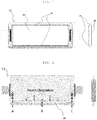
- FIG. 1 illustrates a battery cell according to the present invention, in which a left side of FIG. 1 is a plan view of the battery cell and a right side of FIG. 1 is a side view of the battery cell.
- a battery cell 10 includes an electrode assembly and a pouch case in which the electrode assembly is accommodated, wherein the pouch case includes a pouch body m in which the electrode assembly is accommodated and pouch wings w extending from the pouch body.
- the pouch case of the battery cell includes an upper pouch and a lower pouch, and the electrode assembly is accommodated between the upper pouch and the lower pouch.
- the upper pouch and the lower pouch are provided with electrode assembly accommodating portions formed at a predetermined depth in order to accommodate the electrode assembly.
- a battery cell having a width of a defined size may be manufactured.
- portions corresponding to the electrode assembly accommodating portions of the upper pouch and the lower pouch correspond to the pouch body m according to the present invention, and side portions on both sides of the battery cell except for terrace portions at which electrode tabs are positioned among the side portions at which the upper pouch and the lower pouch are in contact with each other around the electrode assembly, that is, long axes of the side portions correspond to the pouch wings w according to the present invention.
- a length direction refers to a direction from an electrode tab protruding to one side to an electrode tab protruding to the other side in the electrode assembly as illustrated in FIG. 1 .
- FIG. 2 illustrates a difference in an elongation amount at each position of a pouch wing in a case where the pouch wing is folded by 180°.
- positions of both distal ends of the pouch wing w in the length direction are denoted by A and C, respectively, and a middle position of the pouch wing w in the length direction is denoted by B.
- a sealing surface of the pouch has a higher rigidity than that of a non-sealing surface, and thus, does not elongate well as compared with the non-sealing surface.
- the regions A and C have a small elongation amount due to the sealing surfaces of the terrace portions, where the region B has a large elongation amount since there are no such structures.
- a difference in the elongation is generated between the end portions A and C of the pouch wing w and the central portion B of the pouch wing w, such that a meandering is generated in the folding line at the time of folding the pouch wing w.
- large folding non-uniformity due to the meandering may appear.
- FIG. 3 is a photograph illustrating an example in which a folding defect actually occurs in a case where the pouch wing is folded by 180°. As illustrated in FIG. 3 , due to the difference in the elongation amount at each point, a folding amount at both ends of the pouch wing w may be large and a folding amount at a central portion of the pouch wing w may be small.
- factors having an influence on a decrease in a folding amount of the central portion are a forming depth of a battery cell assembly at the time of packaging-side-sealing the pouch case and a height of resealing and a degassing state at the time of degassing, and in common, as a length of the battery cell increases, a length of a region that may be elongated increases, such that a risk that a folding failure will occur increases in a battery cell has a large width.
- the present invention may overcome the difference in the elongation amount at each position and prevent a meandering in a folding process by forming a pre-folding line PFL on the pouch wing w and folding the pouch wing w on the basis of the pre-folding line PFL, in order to solve such problems.
- an apparatus of folding a pouch case of a battery cell includes a line forming unit 100 forming a pre-folding line PFL recessed at a predetermined depth along a length direction of the pouch wing w on the pouch wing w and a folding unit 200 arranged on a path through which the pouch case is transported and folding the pouch wing w on which the pre-folding line PFL is formed, on the basis of the pre-folding line PFL.
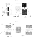
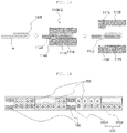
- FIG. 4 illustrates a line forming unit according to a first embodiment of the present invention.
- the line forming unit 100A according to the first embodiment of the present invention may include a pre-heating press 110A heat-pressing the pouch wing w in order to soften the pouch wing w whose rigidity is increased by sealing and a line forming press 120A pressing the pouch wing w softened by the pre-heating press 110A to form the pre-folding line PFL.
- the pre-folding line PFL recessed downward of the pouch wing w may be formed by heat-pressing the pouch wing w through the pre-heating press 110A to soften the pouch wing w and pressing the softened pouch wing w through the line forming press 120A.
- the line forming press 120A includes an upper pressing surface 121A and a lower pressing surface 123A that compress the pouch wing w, a protruding portion 122A protruding downward and extending to be elongated in the length direction of the pouch wing w is formed on the upper pressing surface 121A, and an avoiding portion 124A depressed downward so as to correspond to the protruding portion 122A of the upper pressing surface is formed in the lower pressing surface 123A. Therefore, the pouch wing w may be softened through compression of the pre-heating press 110A, and the pre-folding line PFL may be formed on the softened pouch wing w through compression of the line forming press 120A.
- a knife is further provided on one side of an upper press of the line forming press 120A. Therefore, when the upper press descends, the knife descends together with the upper press, such that forming of the pre-folding line PFL and cutting of the pouch wing w may be simultaneously performed.
- FIG. 5 illustrates a line forming unit according to a second embodiment of the present invention
- FIG. 6 illustrates forming a pre-folding line by pressing the pouch wing with the line forming unit according to the second embodiment
- the line forming unit 100B according to the second embodiment of the present invention may include a heating press 110B for forming the pre-folding line PFL simultaneously with softening the pouch wing w by heat-pressing the pouch wing w
- the heating press 110B may include an upper pressing surface 111B and a lower pressing surface 113B that compress the pouch wing
- a protruding portion 112B protruding downward and extending to be elongated in the length direction of the pouch wing w may be formed on the upper pressing surface 111B
- an avoiding portion 114B depressed downward so as to correspond to the protruding portion 112B may be formed in the lower pressing surface 113B. Therefore, the pre-folding line PFL may be formed on the pouch
- the line forming unit 100B according to the second embodiment of the present invention may form the pre-folding line PFL simultaneously with the softening of the sealing surface only with the heating press 110B to decrease the number of processes and increase a process speed as compared with the line forming unit 100A according to the first embodiment including the pre-heating press 110A and the line forming press 120A.
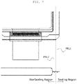
- FIG. 7 illustrates a battery cell in which the pre-folding line is formed on the pouch wing by the line forming unit.
- the pre-folding line PFL recessed downward of the pouch wing w may be formed on the pouch wing w.
- a sealing surface S which is a region in which the upper pouch and the lower pouch are sealed at the time of packaging-side-sealing the pouch case, may be formed on the pouch wing w.
- the sealing surface S may be formed over the entire region of the pouch wing w, but since it is preferable that the sealing surface S is formed only on an outer side portion of the pouch wing w when considering an insulation resistance of the battery cell. Therefore, as illustrated in FIG. 7 , a sealing region may be formed only on the outer side portion of the pouch wing, and a non-sealing region may be formed on an inner side portion of the pouch wing w.
- the line forming unit 100B may include a first heating press 110B-1 forming a first pre-folding line PFL1 on the pouch wing w and a second heating press 110B-2 forming a second pre-folding line PFL2 on the pouch wing on which the first pre-folding line PFL1 is formed. Therefore, as illustrated in FIG. 7 , the first pre-folding line PFL1 and the second pre-folding line PFL2 may be formed on the pouch wing w. In this case, the first pre-folding line PFL1 may be formed on the sealing surface of the pouch wing, and the second pre-folding line PFL2 may be formed on the non-sealing surface of the pouch wing.
- the sealing surface S may be formed only on the outer side of the pouch wing w. Therefore, the first pre-folding line PFL1 may be formed on the outer side of the pouch wing w, and the second pre-folding line PFL2 may be formed on the inner side of the pouch wing w as compared with the first pre-folding line PFL1.
- a heat and a pressure applied to the pouch wing w by the second heating press 110B-2 in order to form the second pre-folding line PFL2 are lower than a heat and a pressure applied to the pouch wing w by the first heating press 110B-1 in order to form the first pre-folding line PFL1.
- a temperature of the second heating press 110B-2 may be 90°C to 120°C and a pressure of the second heating press 110B-2 may be 0.2 to 0.4 Mpa
- a temperature and a pressure of the first heating press 110B-1 may be greater than those of the second heating press 110B-2.
- the first pre-folding line PFL1 is formed on the sealing surface formed by melting a polypropylene (PP) layer in the pouch, even through a high temperature or a high pressure is applied to the pouch wing w, a probability that a defect of an insulation resistance will occur is low, while since the second pre-folding line PFL2 is formed on the non-sealing surface, in a case where a high temperature or a high pressure is applied to the pouch wing w, the PP layer in the pouch is melted, such that a probability that a defect of an insulation resistance will occur is high, and as compared with the first pre-folding line PFL1, the second pre-folding line PFL2 is positioned closer to a body direction, that is, the pouch body m in which the electrode assembly is accommodated, and thus receives a greater insulation influence. Therefore, it is preferable to ease the conditions for forming the second pre-folding line PFL2 as compared with the conditions for forming the first pre-folding line PFL1.
- a heat and a pressure should be applied from the outside to the pouch wing in order to form the first pre-folding line PFL1 and the second pre-folding line PFL2.
- chemical and/or physical properties of the pouch wing w are changed, such that deterioration characteristics of the first pre-folding line PFL1 and the sealing surface except for the first pre-folding line PFL1 may become different from each other and deterioration characteristics of the second pre-folding line PFL2 and the non-sealing surface except for the second pre-folding line PFL2 may become different from each other.
- deterioration characteristics of the first pre-folding line PFL1 and deterioration characteristics of the second pre-folding line PFL2 may become different from each other.
- first and second pre-folding lines PFL1 and PFL2 may be formed and the conditions for forming the first pre-folding line PFL1 and the second pre-folding line PFL2 may be made to be different from each other, using two sets of pre-heating presses 110A and line forming presses 120A according to the first embodiment as well as the line forming unit 100B according to the second embodiment.
- the first and second pre-folding lines PFL1 and PFL2 may be formed using one heating press 110B or one set of pre-heating press 110A and line forming press 120A in a manner of moving the pouch case.
- the folding unit 200 includes a plurality of unit rollers 210 arranged along the path through which the pouch case is transported, at least one of the plurality of unit rollers 210 includes an upper roller 211 and a lower roller 212, an accommodating groove 213 in which a portion protruding downward of the pre-folding line PFL is accommodated is formed in the lower roller 212, and the lower roller 212 is formed so that an outer side of the accommodating groove 212c has a predetermined angle with respect to a horizontal direction, such that the pouch wing w may be folded on the basis of the pre-folding line PFL.
- the folding unit 200 may include a first folding unit 200A folding the pouch wing by 90°, a second folding unit 200B folding the pouch wing folded by 90° by 180°, and a third folding unit 200C additionally folding the pouch wing folded by 180° by 90°. Therefore, the pouch wing w may be folded by 270° in total.
- the first folding unit 200A may include a plurality of first unit rollers 210A arranged along the path through which the pouch case is transported, each of the first unit rollers 210A may include an upper roller 211A and a lower roller 212A, the third folding unit 200C may include a plurality of third unit rollers 210C arranged along the path through which the pouch case is transported, each of the third unit rollers 210C may include an upper roller 211C and a lower roller 212C, an accommodating groove 213A in which a portion protruding downward of the first pre-folding line PFL1 is accommodated may be formed in the lower roller 212A of the first unit roller 210A, and an accommodating groove 213C in which a portion protruding downward of the second pre-folding line PFL2 is accommodated may be formed in the lower roller 212C of the third unit roller 210C.
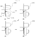
- FIGS. 8A to 8D illustrate side surfaces of the first unit rollers of the first folding unit
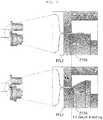
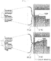
- FIG. 9 illustrates the first unit roller (upper portion of FIG. 9 ) of FIG. 8A and the first unit roller (lower portion of FIG. 9 ) of FIG. 8C .
- Each first unit roller 210A includes the upper roller 211A and the lower roller 212A.
- the accommodating groove 213A in which a portion protruding downward of the first pre-folding line PFL1 is accommodated may be formed in the lower roller 212A, and the lower roller 212A is formed so that an outer side of the accommodating groove 213A has a predetermined angle with respect to the horizontal direction.
- the outer side of the accommodating groove 213A refers to an opposite side to a body direction, that is, a direction toward the pouch body m.
- the predetermined angle that the lower roller 212A of the first unit roller has with respect to the horizontal direction may be 0° or more and 90° or less, and each first unit roller 210A is arranged so that an inclined angle of the lower roller 212A of each first unit roller is increased toward a direction in which the pouch case is transported, such that the pouch wing w may be folded with a concave portion of the first pre-folding line PFL1 being an inner side on the basis of the first pre-folding line PFL1.
- FIGS. 10A to 10D illustrate side surfaces of the third unit rollers of the third folding unit
- FIG. 11 illustrates the third unit roller (upper portion of FIG. 11 ) of FIG. 10A and the third unit roller (lower portion of FIG. 11 ) of FIG. 10C
- the third unit roller 210C may basically have the same structure as that of the first unit roller 210A, an accommodating groove 213C in which a portion protruding downward of the second pre-folding line PFL2 is accommodated may be formed in the lower roller 212C of the third unit roller, and the accommodating groove 213C of the lower roller of the third unit roller may be formed inside the accommodating groove 213A of the lower roller of the first unit roller.
- the first and second pre-folding lines PFL1 and PFL2 may be formed on the pouch wing w by one heating press 110B, and two accommodating grooves in which protruding portions of the first and second pre-folding lines PFL1 and PFL2 are accommodated may be formed in the lower roller 212A of the first folding unit to more firmly guide the pouch wing w at the time of folding the pouch wing w.
- FIGS. 12A to 12D illustrate side surfaces of second unit rollers of the second folding unit.
- the second folding unit 200B may also include a plurality of second unit rollers 210B along the direction in which the pouch case is transported, and each of the second unit rollers may include an upper roller 211B, a lower roller 212B, and a stripper 213B provided on one side of the upper roller 211B to perform a folding guide function of the pouch wing w.
- the stripper 213B may support a folded portion of the pouch wing w, that is, the concave portion of the first pre-folding line PFL1 to allow the pouch wing w to be folded on the basis of the first pre-folding line PFL1.
- FIG. 13 illustrates forming a second pre-folding line on the pouch wing folded by 180°
- the second heating press 110B-2 forming the second pre-folding line PFL2 is illustrated.
- the first heating press 110B-1 may form the first pre-folding line PFL1 on the pouch wing w before the first folding unit 200A folds the pouch wing w by 90°
- the second heating press 110B-2 may form the second pre-folding line PFL2 on the pouch wing w after the second folding unit 200B folds the pouch wing w by 180° and before the third folding unit 200C additionally folds the pouch wing w by 90°.
- the second heating press 110B-2 may include a folded portion upper pressing surface 115B and a folded portion lower pressing surface 117B that compress a 180° folded portion 180f of the pouch wing formed by folding the pouch wing w by 180°
- the folded portion upper pressing surface 155B may be formed at a position higher than the upper pressing surface 111B pressing the pouch wing w from the top rather than the 180° folded portion 180f
- the folded portion lower pressing surface 117B may be formed on the same line as the lower pressing surface 113B pressing the pouch wing w from the bottom rather than the 180° folded portion 180f.
- the second heating press 110B-2 is capable of pressing the 180° folded portion 180f, such that the 180° folded portion 180f of the pouch wing may be compressed simultaneously with forming the second pre-folding line PFL2 through the compression of the second heating press 110B-2.
- FIG. 14 illustrates an apparatus of folding a pouch case according to an embodiment of the present invention.
- the apparatus of folding a pouch case according to an embodiment of the present invention may mainly include a line forming unit 100 and a folding unit 200, and may further include a compressing unit 300 including a first compressing unit 300A compressing a 180° folded portion 180f of a pouch wing folded by 180° and a second compressing unit 300B compressing a 90° folded portion 90f of the pouch wing folded by 90°.
- the compressing unit 300 may also include a plurality of unit rollers 310 arranged along a transport path of the pouch case and each including an upper roller 311 and a lower roller 312.
- the first pre-folding line is formed before the pouch wing is folded and the pouch wing is folded by 180° on the basis of the first pre-folding line
- the second pre-folding line is formed before the pouch wing folded by 180° is folded and the pouch wing is additionally folded by 90° on the basis of the second pre-folding line, such that a difference in an elongation amount at each position of the pouch wing at the time of folding the pouch wing may be overcome, and a meandering of the folding line may be certainly prevented.
- the method of folding a pouch case according to an embodiment of the present invention may include forming the pre-folding line recessed at a predetermined depth along the length direction of the pouch wing on the pouch wing; and folding the pouch wing on which the pre-folding line is formed, on the basis of the pre-folding line.
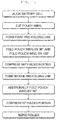
- FIG. 15 illustrates a flowchart of a method of folding a pouch case according to an embodiment of the present invention.
- the battery cell that is, the pouch case in which the electrode assembly is accommodated and the packaging-side-sealing is performed
- the pouch wing on which the first pre-folding line is formed may be folded by 180° by folding the pouch wing by 90° and folding the pouch wing folded by 90° by 90° by the first and second folding units
- the 180° folded portion of the pouch wing formed by folding the pouch wing by 180° may be compressed by the first compressing unit
- the second pre-folding line may be formed on the pouch wing in which the 180° folded portion is compressed, by the second line forming unit
- the pouch wing on which the second pre-folding line is formed may be additionally folded by 90° by the third folding unit, the 90° folded portion of the pouch wing
- the method of folding a pouch case may mainly include forming the pre-folding line on the pouch wing before folding the pouch wing and folding the pouch wing on the basis of the first pre-folding line, wherein the forming of the pre-folding line on the pouch wing may include forming the first pre-folding line on the pouch wing and forming the second pre-folding line on the pouch wing, and the folding of the pouch wing may include folding the pouch wing on which the first pre-folding line is formed, by 90°, folding the pouch wing folded by 90° by 180°, and additionally folding the pouch wing folded by 180° by 90°.
- the first pre-folding line may be formed on the sealing surface of the pouch wing
- the second pre-folding line may be formed on the non-sealing surface of the pouch wing
- a heat and a pressure applied to the pouch wing in order to form the second pre-folding line may be lower than a heat and a pressure applied to the pouch wing in order to form the first pre-folding line.
- the compression of the 180° folded portion of the pouch wing formed by folding the pouch wing by 180° may be simultaneously performed.
- the method of folding a pouch case may further include aligning the pouch case and finally cutting the side end portion of the pouch, before the forming of the first pre-folding line, compressing a pouch wing folded portion formed by folding the pouch wing by 180°, after the folding of the pouch wing by 180°, compressing a pouch wing folded portion formed by additionally folding the pouch wing by 90°, after the additional folding of the pouch wing by 90°, and passing the pouch case through the sizing roller in order to make a size of the pouch case uniform, after the compressing of the pouch wing folded portion formed by additionally folding the pouch wing by 90°.
- the pouch wing may be folded to finally manufacture the battery cell.
- the pouch wing formed on one side of the pouch body may be first folded, a transport direction of the pouch case may be changed, and the pouch wing formed on the other side of the pouch body may then be folded.
- a case where the pouch wings extend from the pouch body to both sides has been described in the present invention, but the present invention may also be applied to a case where the pouch case is bent to surround a long side of one side of the electrode assembly, such that the pouch wing is formed only on one side of the pouch body.
Landscapes
- Chemical & Material Sciences (AREA)
- Chemical Kinetics & Catalysis (AREA)
- Electrochemistry (AREA)
- General Chemical & Material Sciences (AREA)
- Engineering & Computer Science (AREA)
- Mechanical Engineering (AREA)
- Manufacturing & Machinery (AREA)
- Physics & Mathematics (AREA)
- Thermal Sciences (AREA)
- Sealing Battery Cases Or Jackets (AREA)
- Making Paper Articles (AREA)
- Secondary Cells (AREA)
Applications Claiming Priority (2)
| Application Number | Priority Date | Filing Date | Title |
|---|---|---|---|
| KR20190121131 | 2019-09-30 | ||
| KR1020200122800A KR102403858B1 (ko) | 2019-09-30 | 2020-09-23 | 배터리 셀의 파우치 케이스 폴딩 장치 및 방법 |
Publications (2)
| Publication Number | Publication Date |
|---|---|
| EP3799180A2 true EP3799180A2 (de) | 2021-03-31 |
| EP3799180A3 EP3799180A3 (de) | 2021-07-07 |
Family
ID=72670650
Family Applications (1)
| Application Number | Title | Priority Date | Filing Date |
|---|---|---|---|
| EP20199104.9A Pending EP3799180A3 (de) | 2019-09-30 | 2020-09-29 | Vorrichtung und verfahren zum falten der beutelhülle einer batteriezelle |
Country Status (4)
| Country | Link |
|---|---|
| US (1) | US11695177B2 (de) |
| EP (1) | EP3799180A3 (de) |
| KR (2) | KR102658191B1 (de) |
| CN (3) | CN112582715B (de) |
Cited By (3)
| Publication number | Priority date | Publication date | Assignee | Title |
|---|---|---|---|---|
| EP4057409A3 (de) * | 2021-03-10 | 2022-11-16 | SK On Co., Ltd. | Vorrichtung zur herstellung einer batteriezelle |
| EP4123792A1 (de) * | 2021-07-19 | 2023-01-25 | SK On Co., Ltd. | Beutelartige sekundärbatterie und verfahren zur herstellung davon |
| EP4366013A1 (de) * | 2022-11-03 | 2024-05-08 | SK On Co., Ltd. | Vorrichtung zur herstellung einer beutelartigen wiederaufladbaren batterie |
Families Citing this family (6)
| Publication number | Priority date | Publication date | Assignee | Title |
|---|---|---|---|---|
| KR102262441B1 (ko) * | 2020-04-03 | 2021-06-09 | 주식회사 클레버 | 전지셀의 폴딩 공정용 사이징 롤러 장치 |
| KR20230119552A (ko) * | 2022-02-07 | 2023-08-16 | 주식회사 엘지에너지솔루션 | 파우치형 이차전지 실링부의 폴딩장치 및 폴딩방법 |
| JP7852595B2 (ja) * | 2022-11-04 | 2026-04-28 | トヨタ自動車株式会社 | 二次電池の製造装置 |
| KR20250020810A (ko) * | 2023-08-04 | 2025-02-11 | 에스케이온 주식회사 | 파우치 폴딩 방법 및 장치 |
| KR20250146394A (ko) * | 2024-04-01 | 2025-10-13 | 에스케이온 주식회사 | 폴딩 가이드 라인 성형장치 및 배터리 셀 |
| KR20260045044A (ko) * | 2024-09-26 | 2026-04-03 | 에스케이온 주식회사 | 이차전지 제조설비 및 제조방법 |
Citations (1)
| Publication number | Priority date | Publication date | Assignee | Title |
|---|---|---|---|---|
| KR101766966B1 (ko) | 2015-09-17 | 2017-08-09 | 정종홍 | 이차 전지의 파우치 폴딩 장치 |
Family Cites Families (23)
| Publication number | Priority date | Publication date | Assignee | Title |
|---|---|---|---|---|
| KR100319108B1 (ko) | 1999-04-16 | 2001-12-29 | 김순택 | 이차 전지의 케이스 |
| JP2001160379A (ja) | 1999-12-01 | 2001-06-12 | Toshiba Battery Co Ltd | フィルム外装型電池の外装成形装置 |
| JP4806837B2 (ja) * | 2000-04-07 | 2011-11-02 | 大日本印刷株式会社 | ポリマー電池外装体の製造方法 |
| KR20030093362A (ko) * | 2002-05-29 | 2003-12-11 | 아이램테크(주) | 폴리머전지 롤폴딩장치 |
| JP4788889B2 (ja) | 2003-10-07 | 2011-10-05 | 日本電気株式会社 | フィルム外装電池およびフィルム外装電池の製造方法 |
| KR100670427B1 (ko) * | 2005-11-29 | 2007-01-16 | 삼성에스디아이 주식회사 | 파우치형 리튬 이차 전지 |
| KR100876254B1 (ko) * | 2007-07-20 | 2008-12-26 | 삼성에스디아이 주식회사 | 파우치형 이차전지 |
| KR100954879B1 (ko) * | 2007-12-04 | 2010-04-28 | 삼성전기주식회사 | 안테나 내장형 인쇄회로기판 |
| KR101245282B1 (ko) * | 2011-03-09 | 2013-03-19 | 주식회사 엘지화학 | 파우치형 이차전지 및 이의 제조 방법 |
| JP6035754B2 (ja) * | 2012-01-31 | 2016-11-30 | 凸版印刷株式会社 | 蓄電デバイス |
| KR20140005614A (ko) * | 2012-07-05 | 2014-01-15 | 주식회사 엘지화학 | 파우치 케이스 성형 장치, 파우치 케이스 성형 지그, 이를 이용하여 제조된 파우치 케이스 및 파우치 케이스 제조 방법 |
| KR101492691B1 (ko) | 2012-08-24 | 2015-02-12 | 주식회사 엘지화학 | 실링툴 |
| KR20140064406A (ko) | 2012-11-20 | 2014-05-28 | 주식회사 엘지화학 | 폴딩 홈을 구비하는 배터리 셀 |
| KR101832010B1 (ko) * | 2013-11-28 | 2018-02-23 | 주식회사 엘지화학 | 파우치 폴딩 방법 및 이를 이용한 이차 전지 |
| KR20150072107A (ko) * | 2013-12-19 | 2015-06-29 | 주식회사 엘지화학 | 미 열융착 라인을 통해 파우치형 케이스의 주변 부위가 접힌 이차전지 |
| KR20150125263A (ko) | 2014-04-30 | 2015-11-09 | 주식회사 엘지화학 | 전지케이스용 실링 장치 및 이를 사용하여 생산되는 전지셀 |
| KR101802296B1 (ko) | 2015-02-16 | 2017-11-28 | 주식회사 엘지화학 | 전지케이스의 외주면을 가열 및 가압하는 프레스를 포함하는 실링 장치 |
| KR102258656B1 (ko) * | 2015-11-05 | 2021-05-31 | 에스케이이노베이션 주식회사 | 이차전지용 파우치의 폴딩 장치 |
| KR20180010563A (ko) * | 2016-07-21 | 2018-01-31 | 충북대학교 산학협력단 | 2차전지 파우치의 사이드 연속폴딩장치 |
| KR102158144B1 (ko) | 2016-08-12 | 2020-09-21 | 주식회사 엘지화학 | 이차전지 및 그의 제조방법 |
| KR102064460B1 (ko) * | 2016-09-12 | 2020-01-10 | 주식회사 엘지화학 | 이차전지용 파우치 외장재, 이를 이용한 파우치형 이차전지 및 그 제조 방법 |
| CN109997242B (zh) * | 2016-12-20 | 2023-06-20 | Sk新能源株式会社 | 袋型二次电池 |
| KR101974443B1 (ko) * | 2018-04-09 | 2019-05-02 | 김영훈 | 이차전지 셀의 테라스 자동 폴딩 장치 |
-
2020
- 2020-09-28 US US17/034,940 patent/US11695177B2/en active Active
- 2020-09-29 EP EP20199104.9A patent/EP3799180A3/de active Pending
- 2020-09-30 CN CN202011060989.7A patent/CN112582715B/zh active Active
- 2020-09-30 CN CN202410388445.5A patent/CN118281279A/zh active Pending
- 2020-09-30 CN CN202410388016.8A patent/CN118281278A/zh active Pending
-
2022
- 2022-05-25 KR KR1020220063990A patent/KR102658191B1/ko active Active
- 2022-05-25 KR KR1020220063991A patent/KR102598860B1/ko active Active
Patent Citations (1)
| Publication number | Priority date | Publication date | Assignee | Title |
|---|---|---|---|---|
| KR101766966B1 (ko) | 2015-09-17 | 2017-08-09 | 정종홍 | 이차 전지의 파우치 폴딩 장치 |
Cited By (5)
| Publication number | Priority date | Publication date | Assignee | Title |
|---|---|---|---|---|
| EP4057409A3 (de) * | 2021-03-10 | 2022-11-16 | SK On Co., Ltd. | Vorrichtung zur herstellung einer batteriezelle |
| EP4224586A3 (de) * | 2021-03-10 | 2023-08-16 | SK On Co., Ltd. | Vorrichtung zur herstellung einer batteriezelle |
| EP4123792A1 (de) * | 2021-07-19 | 2023-01-25 | SK On Co., Ltd. | Beutelartige sekundärbatterie und verfahren zur herstellung davon |
| US12068490B2 (en) | 2021-07-19 | 2024-08-20 | Sk On Co., Ltd. | Pouch-type secondary battery and method for manufacturing the same |
| EP4366013A1 (de) * | 2022-11-03 | 2024-05-08 | SK On Co., Ltd. | Vorrichtung zur herstellung einer beutelartigen wiederaufladbaren batterie |
Also Published As
| Publication number | Publication date |
|---|---|
| KR20220073722A (ko) | 2022-06-03 |
| KR20220075298A (ko) | 2022-06-08 |
| KR102658191B1 (ko) | 2024-04-18 |
| CN112582715B (zh) | 2024-04-19 |
| CN118281278A (zh) | 2024-07-02 |
| US11695177B2 (en) | 2023-07-04 |
| US20210098751A1 (en) | 2021-04-01 |
| CN112582715A (zh) | 2021-03-30 |
| KR102598860B1 (ko) | 2023-11-07 |
| EP3799180A3 (de) | 2021-07-07 |
| CN118281279A (zh) | 2024-07-02 |
Similar Documents
| Publication | Publication Date | Title |
|---|---|---|
| EP3799180A2 (de) | Vorrichtung und verfahren zum falten der beutelhülle einer batteriezelle | |
| KR102403858B1 (ko) | 배터리 셀의 파우치 케이스 폴딩 장치 및 방법 | |
| CN203026592U (zh) | 电池单元 | |
| US9300003B2 (en) | Meandering correction apparatus for electrode assembly | |
| KR101759570B1 (ko) | 전극 시트를 고정하는 구조의 롤러를 포함하는 노칭 장치 | |
| EP4106035B1 (de) | Elektrodenanordnung mit anode und anodenblatt mit verbesserten elektrodenstapelungseigenschaften und herstellungsverfahren dafür | |
| KR20150089470A (ko) | 두께가 두꺼운 구조의 무지부를 포함하는 전극 | |
| KR20180089014A (ko) | 절연성 테이프를 전지셀의 외주 실링부에 부가하는 테이핑 장치 | |
| US20230369632A1 (en) | Apparatus and Method of Folding Pouch Case of Battery Cell | |
| US20230369633A1 (en) | Apparatus and Method of Folding Pouch Case of Battery Cell | |
| JP7687777B2 (ja) | 多重ローラーシステム、電池缶の成形装置および成形方法 | |
| JP2023539658A (ja) | セル、電池及び電池パック | |
| KR20240011650A (ko) | 원통형 배터리, 배터리 팩 및 자동차 | |
| KR102940366B1 (ko) | 파우치형 셀, 이의 실링부 성형 방법 및 장치 | |
| KR20230013621A (ko) | 전극 시트 가공 방법 및 가공 장치 | |
| KR102781215B1 (ko) | 폴딩부를 포함하는 전극 제조방법 및 폴딩부를 포함하는 전극 시트 | |
| EP4535473A1 (de) | Elektrodenanordnung und verfahren zur herstellung einer elektrodenanordnung | |
| US20120276773A1 (en) | Method for connecting cell outgoing conductors and battery arrangement | |
| JP7803479B2 (ja) | スタック型電極体のサイドシーリング装置、スタック型電極体を有する二次電池およびその製造方法 | |
| JP7810341B2 (ja) | スタック型電極体のサイドシーリング装置、スタック型電極体を有する二次電池およびその製造方法 | |
| EP4057409A2 (de) | Vorrichtung zur herstellung einer batteriezelle | |
| KR20260033180A (ko) | 파우치형 이차전지 제조장치 및 방법 | |
| EP4503218A2 (de) | Verfahren und vorrichtung zum falten von beuteln | |
| KR20210043481A (ko) | 이차전지 파우치 폴딩용 실링부 포밍장치 | |
| US20250249528A1 (en) | Battery cell current collector straight tab welding |
Legal Events
| Date | Code | Title | Description |
|---|---|---|---|
| PUAI | Public reference made under article 153(3) epc to a published international application that has entered the european phase |
Free format text: ORIGINAL CODE: 0009012 |
|
| STAA | Information on the status of an ep patent application or granted ep patent |
Free format text: STATUS: REQUEST FOR EXAMINATION WAS MADE |
|
| 17P | Request for examination filed |
Effective date: 20200929 |
|
| AK | Designated contracting states |
Kind code of ref document: A2 Designated state(s): AL AT BE BG CH CY CZ DE DK EE ES FI FR GB GR HR HU IE IS IT LI LT LU LV MC MK MT NL NO PL PT RO RS SE SI SK SM TR |
|
| AX | Request for extension of the european patent |
Extension state: BA ME |
|
| PUAL | Search report despatched |
Free format text: ORIGINAL CODE: 0009013 |
|
| AK | Designated contracting states |
Kind code of ref document: A3 Designated state(s): AL AT BE BG CH CY CZ DE DK EE ES FI FR GB GR HR HU IE IS IT LI LT LU LV MC MK MT NL NO PL PT RO RS SE SI SK SM TR |
|
| RIC1 | Information provided on ipc code assigned before grant |
Ipc: H01M 10/04 20060101AFI20210528BHEP Ipc: B29C 65/00 20060101ALI20210528BHEP Ipc: H01M 50/105 20210101ALI20210528BHEP Ipc: H01M 50/121 20210101ALI20210528BHEP Ipc: H01M 50/136 20210101ALI20210528BHEP |
|
| STAA | Information on the status of an ep patent application or granted ep patent |
Free format text: STATUS: EXAMINATION IS IN PROGRESS |
|
| 17Q | First examination report despatched |
Effective date: 20230104 |
|
| RAP1 | Party data changed (applicant data changed or rights of an application transferred) |
Owner name: SK ON CO., LTD. |
|
| P01 | Opt-out of the competence of the unified patent court (upc) registered |
Effective date: 20230602 |