EP3799253A1 - Verfahren und system zum zurückholen eines batterieverwaltungssystems aus dem ruhemodus - Google Patents
Verfahren und system zum zurückholen eines batterieverwaltungssystems aus dem ruhemodus Download PDFInfo
- Publication number
- EP3799253A1 EP3799253A1 EP20824419.4A EP20824419A EP3799253A1 EP 3799253 A1 EP3799253 A1 EP 3799253A1 EP 20824419 A EP20824419 A EP 20824419A EP 3799253 A1 EP3799253 A1 EP 3799253A1
- Authority
- EP
- European Patent Office
- Prior art keywords
- voltage
- low
- wake
- transformer
- module
- Prior art date
- Legal status (The legal status is an assumption and is not a legal conclusion. Google has not performed a legal analysis and makes no representation as to the accuracy of the status listed.)
- Granted
Links
Images



Classifications
-
- H—ELECTRICITY
- H02—GENERATION; CONVERSION OR DISTRIBUTION OF ELECTRIC POWER
- H02M—APPARATUS FOR CONVERSION BETWEEN AC AND AC, BETWEEN AC AND DC, OR BETWEEN DC AND DC, AND FOR USE WITH MAINS OR SIMILAR POWER SUPPLY SYSTEMS; CONVERSION OF DC OR AC INPUT POWER INTO SURGE OUTPUT POWER; CONTROL OR REGULATION THEREOF
- H02M3/00—Conversion of DC power input into DC power output
- H02M3/22—Conversion of DC power input into DC power output with intermediate conversion into AC
- H02M3/24—Conversion of DC power input into DC power output with intermediate conversion into AC by static converters
- H02M3/28—Conversion of DC power input into DC power output with intermediate conversion into AC by static converters using discharge tubes with control electrode or semiconductor devices with control electrode to produce the intermediate AC
- H02M3/325—Conversion of DC power input into DC power output with intermediate conversion into AC by static converters using discharge tubes with control electrode or semiconductor devices with control electrode to produce the intermediate AC using devices of a triode or a transistor type requiring continuous application of a control signal
- H02M3/335—Conversion of DC power input into DC power output with intermediate conversion into AC by static converters using discharge tubes with control electrode or semiconductor devices with control electrode to produce the intermediate AC using devices of a triode or a transistor type requiring continuous application of a control signal using semiconductor devices only
- H02M3/33507—Conversion of DC power input into DC power output with intermediate conversion into AC by static converters using discharge tubes with control electrode or semiconductor devices with control electrode to produce the intermediate AC using devices of a triode or a transistor type requiring continuous application of a control signal using semiconductor devices only with automatic control of the output voltage or current, e.g. flyback converters
-
- B—PERFORMING OPERATIONS; TRANSPORTING
- B60—VEHICLES IN GENERAL
- B60L—PROPULSION OF ELECTRICALLY-PROPELLED VEHICLES; SUPPLYING ELECTRIC POWER FOR AUXILIARY EQUIPMENT OF ELECTRICALLY-PROPELLED VEHICLES; ELECTRODYNAMIC BRAKE SYSTEMS FOR VEHICLES IN GENERAL; MAGNETIC SUSPENSION OR LEVITATION FOR VEHICLES; MONITORING OPERATING VARIABLES OF ELECTRICALLY-PROPELLED VEHICLES; ELECTRIC SAFETY DEVICES FOR ELECTRICALLY-PROPELLED VEHICLES
- B60L58/00—Methods or circuit arrangements for monitoring or controlling batteries or fuel cells, specially adapted for electric vehicles
- B60L58/10—Methods or circuit arrangements for monitoring or controlling batteries or fuel cells, specially adapted for electric vehicles for monitoring or controlling batteries
-
- B—PERFORMING OPERATIONS; TRANSPORTING
- B60—VEHICLES IN GENERAL
- B60L—PROPULSION OF ELECTRICALLY-PROPELLED VEHICLES; SUPPLYING ELECTRIC POWER FOR AUXILIARY EQUIPMENT OF ELECTRICALLY-PROPELLED VEHICLES; ELECTRODYNAMIC BRAKE SYSTEMS FOR VEHICLES IN GENERAL; MAGNETIC SUSPENSION OR LEVITATION FOR VEHICLES; MONITORING OPERATING VARIABLES OF ELECTRICALLY-PROPELLED VEHICLES; ELECTRIC SAFETY DEVICES FOR ELECTRICALLY-PROPELLED VEHICLES
- B60L3/00—Electric devices on electrically-propelled vehicles for safety purposes; Monitoring operating variables, e.g. speed, deceleration or energy consumption
- B60L3/12—Recording operating variables ; Monitoring of operating variables
-
- B—PERFORMING OPERATIONS; TRANSPORTING
- B60—VEHICLES IN GENERAL
- B60L—PROPULSION OF ELECTRICALLY-PROPELLED VEHICLES; SUPPLYING ELECTRIC POWER FOR AUXILIARY EQUIPMENT OF ELECTRICALLY-PROPELLED VEHICLES; ELECTRODYNAMIC BRAKE SYSTEMS FOR VEHICLES IN GENERAL; MAGNETIC SUSPENSION OR LEVITATION FOR VEHICLES; MONITORING OPERATING VARIABLES OF ELECTRICALLY-PROPELLED VEHICLES; ELECTRIC SAFETY DEVICES FOR ELECTRICALLY-PROPELLED VEHICLES
- B60L58/00—Methods or circuit arrangements for monitoring or controlling batteries or fuel cells, specially adapted for electric vehicles
- B60L58/10—Methods or circuit arrangements for monitoring or controlling batteries or fuel cells, specially adapted for electric vehicles for monitoring or controlling batteries
- B60L58/18—Methods or circuit arrangements for monitoring or controlling batteries or fuel cells, specially adapted for electric vehicles for monitoring or controlling batteries of two or more battery modules
- B60L58/20—Methods or circuit arrangements for monitoring or controlling batteries or fuel cells, specially adapted for electric vehicles for monitoring or controlling batteries of two or more battery modules having different nominal voltages
-
- H—ELECTRICITY
- H01—ELECTRIC ELEMENTS
- H01M—PROCESSES OR MEANS, e.g. BATTERIES, FOR THE DIRECT CONVERSION OF CHEMICAL ENERGY INTO ELECTRICAL ENERGY
- H01M10/00—Secondary cells; Manufacture thereof
- H01M10/42—Methods or arrangements for servicing or maintenance of secondary cells or secondary half-cells
- H01M10/425—Structural combination with electronic components, e.g. electronic circuits integrated to the outside of the casing
-
- H—ELECTRICITY
- H01—ELECTRIC ELEMENTS
- H01M—PROCESSES OR MEANS, e.g. BATTERIES, FOR THE DIRECT CONVERSION OF CHEMICAL ENERGY INTO ELECTRICAL ENERGY
- H01M10/00—Secondary cells; Manufacture thereof
- H01M10/42—Methods or arrangements for servicing or maintenance of secondary cells or secondary half-cells
- H01M10/425—Structural combination with electronic components, e.g. electronic circuits integrated to the outside of the casing
- H01M10/4257—Smart batteries, e.g. electronic circuits inside the housing of the cells or batteries
-
- H—ELECTRICITY
- H02—GENERATION; CONVERSION OR DISTRIBUTION OF ELECTRIC POWER
- H02J—ELECTRIC POWER NETWORKS; CIRCUIT ARRANGEMENTS OR SYSTEMS FOR SUPPLYING OR DISTRIBUTING ELECTRIC POWER; SYSTEMS FOR STORING ELECTRIC ENERGY
- H02J7/00—Circuit arrangements for charging or discharging batteries or for supplying loads from batteries
- H02J7/80—Circuit arrangements for charging or discharging batteries or for supplying loads from batteries including monitoring or indicating arrangements
-
- H—ELECTRICITY
- H02—GENERATION; CONVERSION OR DISTRIBUTION OF ELECTRIC POWER
- H02J—ELECTRIC POWER NETWORKS; CIRCUIT ARRANGEMENTS OR SYSTEMS FOR SUPPLYING OR DISTRIBUTING ELECTRIC POWER; SYSTEMS FOR STORING ELECTRIC ENERGY
- H02J7/00—Circuit arrangements for charging or discharging batteries or for supplying loads from batteries
- H02J7/855—Circuit arrangements for charging or discharging batteries or for supplying loads from batteries with circuits adapted for supplying loads from the battery
-
- H—ELECTRICITY
- H02—GENERATION; CONVERSION OR DISTRIBUTION OF ELECTRIC POWER
- H02J—ELECTRIC POWER NETWORKS; CIRCUIT ARRANGEMENTS OR SYSTEMS FOR SUPPLYING OR DISTRIBUTING ELECTRIC POWER; SYSTEMS FOR STORING ELECTRIC ENERGY
- H02J7/00—Circuit arrangements for charging or discharging batteries or for supplying loads from batteries
- H02J7/90—Regulation of charging or discharging current or voltage
-
- H—ELECTRICITY
- H02—GENERATION; CONVERSION OR DISTRIBUTION OF ELECTRIC POWER
- H02M—APPARATUS FOR CONVERSION BETWEEN AC AND AC, BETWEEN AC AND DC, OR BETWEEN DC AND DC, AND FOR USE WITH MAINS OR SIMILAR POWER SUPPLY SYSTEMS; CONVERSION OF DC OR AC INPUT POWER INTO SURGE OUTPUT POWER; CONTROL OR REGULATION THEREOF
- H02M3/00—Conversion of DC power input into DC power output
- H02M3/22—Conversion of DC power input into DC power output with intermediate conversion into AC
- H02M3/24—Conversion of DC power input into DC power output with intermediate conversion into AC by static converters
- H02M3/28—Conversion of DC power input into DC power output with intermediate conversion into AC by static converters using discharge tubes with control electrode or semiconductor devices with control electrode to produce the intermediate AC
- H02M3/325—Conversion of DC power input into DC power output with intermediate conversion into AC by static converters using discharge tubes with control electrode or semiconductor devices with control electrode to produce the intermediate AC using devices of a triode or a transistor type requiring continuous application of a control signal
- H02M3/335—Conversion of DC power input into DC power output with intermediate conversion into AC by static converters using discharge tubes with control electrode or semiconductor devices with control electrode to produce the intermediate AC using devices of a triode or a transistor type requiring continuous application of a control signal using semiconductor devices only
- H02M3/33538—Conversion of DC power input into DC power output with intermediate conversion into AC by static converters using discharge tubes with control electrode or semiconductor devices with control electrode to produce the intermediate AC using devices of a triode or a transistor type requiring continuous application of a control signal using semiconductor devices only of the forward type
-
- H—ELECTRICITY
- H02—GENERATION; CONVERSION OR DISTRIBUTION OF ELECTRIC POWER
- H02M—APPARATUS FOR CONVERSION BETWEEN AC AND AC, BETWEEN AC AND DC, OR BETWEEN DC AND DC, AND FOR USE WITH MAINS OR SIMILAR POWER SUPPLY SYSTEMS; CONVERSION OF DC OR AC INPUT POWER INTO SURGE OUTPUT POWER; CONTROL OR REGULATION THEREOF
- H02M3/00—Conversion of DC power input into DC power output
- H02M3/22—Conversion of DC power input into DC power output with intermediate conversion into AC
- H02M3/24—Conversion of DC power input into DC power output with intermediate conversion into AC by static converters
- H02M3/28—Conversion of DC power input into DC power output with intermediate conversion into AC by static converters using discharge tubes with control electrode or semiconductor devices with control electrode to produce the intermediate AC
- H02M3/325—Conversion of DC power input into DC power output with intermediate conversion into AC by static converters using discharge tubes with control electrode or semiconductor devices with control electrode to produce the intermediate AC using devices of a triode or a transistor type requiring continuous application of a control signal
- H02M3/335—Conversion of DC power input into DC power output with intermediate conversion into AC by static converters using discharge tubes with control electrode or semiconductor devices with control electrode to produce the intermediate AC using devices of a triode or a transistor type requiring continuous application of a control signal using semiconductor devices only
- H02M3/33569—Conversion of DC power input into DC power output with intermediate conversion into AC by static converters using discharge tubes with control electrode or semiconductor devices with control electrode to produce the intermediate AC using devices of a triode or a transistor type requiring continuous application of a control signal using semiconductor devices only having several active switching elements
- H02M3/33576—Conversion of DC power input into DC power output with intermediate conversion into AC by static converters using discharge tubes with control electrode or semiconductor devices with control electrode to produce the intermediate AC using devices of a triode or a transistor type requiring continuous application of a control signal using semiconductor devices only having several active switching elements having at least one active switching element at the secondary side of an isolation transformer
- H02M3/33592—Conversion of DC power input into DC power output with intermediate conversion into AC by static converters using discharge tubes with control electrode or semiconductor devices with control electrode to produce the intermediate AC using devices of a triode or a transistor type requiring continuous application of a control signal using semiconductor devices only having several active switching elements having at least one active switching element at the secondary side of an isolation transformer having a synchronous rectifier circuit or a synchronous freewheeling circuit at the secondary side of an isolation transformer
-
- B—PERFORMING OPERATIONS; TRANSPORTING
- B60—VEHICLES IN GENERAL
- B60L—PROPULSION OF ELECTRICALLY-PROPELLED VEHICLES; SUPPLYING ELECTRIC POWER FOR AUXILIARY EQUIPMENT OF ELECTRICALLY-PROPELLED VEHICLES; ELECTRODYNAMIC BRAKE SYSTEMS FOR VEHICLES IN GENERAL; MAGNETIC SUSPENSION OR LEVITATION FOR VEHICLES; MONITORING OPERATING VARIABLES OF ELECTRICALLY-PROPELLED VEHICLES; ELECTRIC SAFETY DEVICES FOR ELECTRICALLY-PROPELLED VEHICLES
- B60L2210/00—Converter types
- B60L2210/10—DC to DC converters
-
- H—ELECTRICITY
- H01—ELECTRIC ELEMENTS
- H01M—PROCESSES OR MEANS, e.g. BATTERIES, FOR THE DIRECT CONVERSION OF CHEMICAL ENERGY INTO ELECTRICAL ENERGY
- H01M10/00—Secondary cells; Manufacture thereof
- H01M10/42—Methods or arrangements for servicing or maintenance of secondary cells or secondary half-cells
- H01M10/425—Structural combination with electronic components, e.g. electronic circuits integrated to the outside of the casing
- H01M2010/4271—Battery management systems including electronic circuits, e.g. control of current or voltage to keep battery in healthy state, cell balancing
-
- H—ELECTRICITY
- H02—GENERATION; CONVERSION OR DISTRIBUTION OF ELECTRIC POWER
- H02J—ELECTRIC POWER NETWORKS; CIRCUIT ARRANGEMENTS OR SYSTEMS FOR SUPPLYING OR DISTRIBUTING ELECTRIC POWER; SYSTEMS FOR STORING ELECTRIC ENERGY
- H02J2105/00—Networks for supplying or distributing electric power characterised by their spatial reach or by the load
- H02J2105/30—Networks for supplying or distributing electric power characterised by their spatial reach or by the load the load networks being external to vehicles, i.e. exchanging power with vehicles
- H02J2105/33—Networks for supplying or distributing electric power characterised by their spatial reach or by the load the load networks being external to vehicles, i.e. exchanging power with vehicles exchanging power with road vehicles
- H02J2105/37—Networks for supplying or distributing electric power characterised by their spatial reach or by the load the load networks being external to vehicles, i.e. exchanging power with vehicles exchanging power with road vehicles exchanging power with electric vehicles [EV] or with hybrid electric vehicles [HEV]
-
- H—ELECTRICITY
- H02—GENERATION; CONVERSION OR DISTRIBUTION OF ELECTRIC POWER
- H02J—ELECTRIC POWER NETWORKS; CIRCUIT ARRANGEMENTS OR SYSTEMS FOR SUPPLYING OR DISTRIBUTING ELECTRIC POWER; SYSTEMS FOR STORING ELECTRIC ENERGY
- H02J2207/00—Details of circuit arrangements for charging or discharging batteries or supplying loads from batteries
- H02J2207/10—Control circuit supply, e.g. means for supplying power to the control circuit
-
- H—ELECTRICITY
- H02—GENERATION; CONVERSION OR DISTRIBUTION OF ELECTRIC POWER
- H02J—ELECTRIC POWER NETWORKS; CIRCUIT ARRANGEMENTS OR SYSTEMS FOR SUPPLYING OR DISTRIBUTING ELECTRIC POWER; SYSTEMS FOR STORING ELECTRIC ENERGY
- H02J9/00—Circuit arrangements for emergency or stand-by power supply, e.g. for emergency lighting
- H02J9/005—Circuit arrangements for emergency or stand-by power supply, e.g. for emergency lighting using a power saving mode
-
- Y—GENERAL TAGGING OF NEW TECHNOLOGICAL DEVELOPMENTS; GENERAL TAGGING OF CROSS-SECTIONAL TECHNOLOGIES SPANNING OVER SEVERAL SECTIONS OF THE IPC; TECHNICAL SUBJECTS COVERED BY FORMER USPC CROSS-REFERENCE ART COLLECTIONS [XRACs] AND DIGESTS
- Y02—TECHNOLOGIES OR APPLICATIONS FOR MITIGATION OR ADAPTATION AGAINST CLIMATE CHANGE
- Y02E—REDUCTION OF GREENHOUSE GAS [GHG] EMISSIONS, RELATED TO ENERGY GENERATION, TRANSMISSION OR DISTRIBUTION
- Y02E60/00—Enabling technologies; Technologies with a potential or indirect contribution to GHG emissions mitigation
- Y02E60/10—Energy storage using batteries
-
- Y—GENERAL TAGGING OF NEW TECHNOLOGICAL DEVELOPMENTS; GENERAL TAGGING OF CROSS-SECTIONAL TECHNOLOGIES SPANNING OVER SEVERAL SECTIONS OF THE IPC; TECHNICAL SUBJECTS COVERED BY FORMER USPC CROSS-REFERENCE ART COLLECTIONS [XRACs] AND DIGESTS
- Y02—TECHNOLOGIES OR APPLICATIONS FOR MITIGATION OR ADAPTATION AGAINST CLIMATE CHANGE
- Y02T—CLIMATE CHANGE MITIGATION TECHNOLOGIES RELATED TO TRANSPORTATION
- Y02T10/00—Road transport of goods or passengers
- Y02T10/60—Other road transportation technologies with climate change mitigation effect
- Y02T10/70—Energy storage systems for electromobility, e.g. batteries
-
- Y—GENERAL TAGGING OF NEW TECHNOLOGICAL DEVELOPMENTS; GENERAL TAGGING OF CROSS-SECTIONAL TECHNOLOGIES SPANNING OVER SEVERAL SECTIONS OF THE IPC; TECHNICAL SUBJECTS COVERED BY FORMER USPC CROSS-REFERENCE ART COLLECTIONS [XRACs] AND DIGESTS
- Y02—TECHNOLOGIES OR APPLICATIONS FOR MITIGATION OR ADAPTATION AGAINST CLIMATE CHANGE
- Y02T—CLIMATE CHANGE MITIGATION TECHNOLOGIES RELATED TO TRANSPORTATION
- Y02T10/00—Road transport of goods or passengers
- Y02T10/60—Other road transportation technologies with climate change mitigation effect
- Y02T10/7072—Electromobility specific charging systems or methods for batteries, ultracapacitors, supercapacitors or double-layer capacitors
-
- Y—GENERAL TAGGING OF NEW TECHNOLOGICAL DEVELOPMENTS; GENERAL TAGGING OF CROSS-SECTIONAL TECHNOLOGIES SPANNING OVER SEVERAL SECTIONS OF THE IPC; TECHNICAL SUBJECTS COVERED BY FORMER USPC CROSS-REFERENCE ART COLLECTIONS [XRACs] AND DIGESTS
- Y02—TECHNOLOGIES OR APPLICATIONS FOR MITIGATION OR ADAPTATION AGAINST CLIMATE CHANGE
- Y02T—CLIMATE CHANGE MITIGATION TECHNOLOGIES RELATED TO TRANSPORTATION
- Y02T10/00—Road transport of goods or passengers
- Y02T10/60—Other road transportation technologies with climate change mitigation effect
- Y02T10/72—Electric energy management in electromobility
-
- Y—GENERAL TAGGING OF NEW TECHNOLOGICAL DEVELOPMENTS; GENERAL TAGGING OF CROSS-SECTIONAL TECHNOLOGIES SPANNING OVER SEVERAL SECTIONS OF THE IPC; TECHNICAL SUBJECTS COVERED BY FORMER USPC CROSS-REFERENCE ART COLLECTIONS [XRACs] AND DIGESTS
- Y02—TECHNOLOGIES OR APPLICATIONS FOR MITIGATION OR ADAPTATION AGAINST CLIMATE CHANGE
- Y02T—CLIMATE CHANGE MITIGATION TECHNOLOGIES RELATED TO TRANSPORTATION
- Y02T90/00—Enabling technologies or technologies with a potential or indirect contribution to GHG emissions mitigation
- Y02T90/10—Technologies relating to charging of electric vehicles
- Y02T90/12—Electric charging stations
-
- Y—GENERAL TAGGING OF NEW TECHNOLOGICAL DEVELOPMENTS; GENERAL TAGGING OF CROSS-SECTIONAL TECHNOLOGIES SPANNING OVER SEVERAL SECTIONS OF THE IPC; TECHNICAL SUBJECTS COVERED BY FORMER USPC CROSS-REFERENCE ART COLLECTIONS [XRACs] AND DIGESTS
- Y02—TECHNOLOGIES OR APPLICATIONS FOR MITIGATION OR ADAPTATION AGAINST CLIMATE CHANGE
- Y02T—CLIMATE CHANGE MITIGATION TECHNOLOGIES RELATED TO TRANSPORTATION
- Y02T90/00—Enabling technologies or technologies with a potential or indirect contribution to GHG emissions mitigation
- Y02T90/10—Technologies relating to charging of electric vehicles
- Y02T90/16—Information or communication technologies improving the operation of electric vehicles
Definitions
- This application relates to the field of battery management, and particularly to a wake-up method and wake-up system for a battery management system.
- New energy vehicles will become an important way to reduce vehicle exhaust emission, reduce energy consumption and relieve environmental pressure.
- a new energy vehicle includes a high-voltage electrical system and a low-voltage electrical system. Since there are many high-voltage electrical components on the new energy vehicle, in order to ensure the safety of users and avoid the risk of electrocution, the high-voltage side and the low-voltage side are generally isolated by a transformer.
- BMS Battery Management System
- Embodiments of the present application may provide a wake-up method and a wake-up system for a battery management system, which may provide a stable power source for a low-voltage side through a high-voltage battery pack, and the consumption of lead-acid batteries in a vehicle is reduced.
- a wake-up method for a battery management system which is used in a wake-up system for the battery management system, the wake-up system includes a power battery pack, a low-voltage input port, a conversion unit, a high-voltage control module, a high-voltage transmission module, a synchronous rectifying module and a low-voltage controller, the wake-up method for the battery management system includes:
- a wake-up system for a battery management system including a power battery pack, a low-voltage input port, a conversion unit, a high-voltage control module, a high-voltage transmission module, a synchronous rectifying module and a low-voltage controller, the low-voltage input port is connected to the high-voltage control module through the conversion unit, the high-voltage control module is connected to the power battery pack and the high-voltage transmission module, the high-voltage transmission module is connected to the low-voltage controller through the synchronous rectifying module, and the low-voltage controller is connected to the battery management system; the low-voltage input port is configured to receive a low-voltage power signal; the conversion unit is configured to convert the low-voltage power signal into a high-voltage wake-up signal; the high-voltage control module is configured to receive, under control of the high-voltage wake-up signal, a working voltage provided by the power battery pack, and control the high-volt
- a low-voltage power input through a power charging interface of a low-voltage side may be converted into a high-voltage power signal, to wake up the high-voltage battery pack of a high-voltage side to start working, so that the high-voltage battery pack provides a stable power source for the low-voltage side, thereby the vehicle BMS may be waked up through the low-voltage power signal, and the consumption of lead-acid batteries in the vehicle may be reduced.
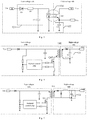
- Fig. 1 is a schematic structural diagram showing a sleep charging wake-up method for a battery management system of an electric vehicle according to an embodiment of the present application.
- a wake-up system 100 for a battery management system in the embodiments of the present application may include a power battery pack 110, a low-voltage input port 120, a conversion unit 130, a high-voltage control module 140, a high-voltage transmission module 150, a synchronous rectifying module 160 and a low-voltage controller 170.
- the low-voltage input port 120 is connected to the high-voltage control module 140 through the conversion unit 130, the high-voltage control module 140 is connected to the power battery pack 110 and the high-voltage transmission module 150, the high-voltage transmission module 150 is connected to the low-voltage controller 170 through the synchronous rectifying module 160, and the low-voltage controller 170 is connected to the battery management system (not shown).
- the low-voltage input port 120 is connected to the high-voltage control module 140 through the conversion unit 130, the high-voltage control module 140 is connected to the power battery pack 110 and the high-voltage transmission module 150, the high-voltage transmission module 150 is connected to the low-voltage controller 170 through the synchronous rectifying module 160, and the low-voltage controller 170 is connected to the battery management system.
- the low-voltage input port 120 is configured to receive a low-voltage power signal.
- the conversion unit 130 is configured to convert the low-voltage power signal into a high-voltage wake-up signal.
- the high-voltage control module 140 is configured to receive, under control of the high-voltage wake-up signal, a working voltage provided by the power battery pack, and control the high-voltage transmission module to be turned on.
- the high-voltage transmission module 150 is configured to provide, when turned on, the working voltage to the synchronous rectifying module, and convert high-voltage electric energy in the power battery pack into low-voltage electric energy.
- the synchronous rectifying module 160 is configured to transmit, under control of the synchronous rectifying module, the low-voltage electric energy to the low-voltage controller, and wake up the battery management system by the low-voltage controller.
- a new energy vehicle since a new energy vehicle includes a high-voltage electrical system and a low-voltage electrical system, in order to ensure the safety of users and avoid the risk of electrocution, high-voltage electrical components in the high-voltage electrical system may be isolated from low-voltage electrical components in the low-voltage electrical system by an isolating component.
- the isolating component may include the conversion unit 130 and the high-voltage transmission module 150.
- the conversion unit 130 and the high-voltage transmission module 150 may achieve an electrical isolation between the high-voltage electrical components and the low-voltage electrical components, the conversion unit 130 may convert the received low-voltage signal into a high-voltage signal, and the high-voltage transmission module 150 may convert the received high-voltage electric energy into low-voltage electric energy.
- the low-voltage side may represent a low-voltage signal input terminal side of the conversion unit 130 and a low-voltage electric energy output terminal side of the high-voltage transmission module 150; and the high-voltage side may represent a high-voltage signal output terminal side of the conversion unit 130 and a high-voltage electric energy input terminal side of the high-voltage transmission module 150.
- the low-voltage electrical components may include the low-voltage input port 120, the synchronous rectifying module 160 and the low-voltage controller 170, and the high-voltage electrical components may include the power battery pack 110 and the high-voltage control module 140.
- a low-voltage charging system of 12 V or 24 V may be input to the low-voltage signal input terminal side.
- a lead-acid battery may be connected to the BMS through the low-voltage controller.
- the low-voltage controller may cut off the connection between the BMS and the lead-acid battery, and at this time, the BMS powers down and enters into sleep due to its powering down.
- the wake-up method given by the battery management system of the wake-up system in the embodiments of the present application may be utilized to prevent the BMS from staying in sleep for a long time, so that the BMS may be able to monitor and handle the condition of the vehicle battery pack.
- SOC State Of Charge
- the wake-up method and the wake-up system for the battery management system according to the embodiments of the present application may wake up the BMS by the low-voltage power signal, and the low-voltage power supply may be a direct current power supply or an alternating current power supply.
- the low-voltage power supply may be a direct current power supply or an alternating current power supply.
- Fig. 2 shows a schematic structural diagram of a wake-up system for a battery management system according to another embodiment of the present application.
- the wake-up system 100 for the battery management system may further include: a first rectifying and filtering unit 121 connected between the low-voltage input port and an input terminal of the conversion unit, and configured to rectify and filter the low-voltage power signal.
- the conversion unit 130 is further configured to convert the rectified and filtered low-voltage power signal into the high-voltage wake-up signal.
- the wake-up system 100 for the battery management system may further include: a filtering module 122 connected to an output terminal of the conversion unit 130, and configured to rectify and filter the high-voltage wake-up signal obtained by the conversion.
- the high-voltage control module 140 is further configured to receive, under control of the rectified and filtered high-voltage wake-up signal, a working voltage provided by the power battery pack, and control the high-voltage transmission module to be turned on.
- the conversion unit 130 may include any of an optocoupler circuit, a flyback power circuit and a forward power circuit.
- the conversion unit in the embodiments of the present application will be described in detail below with reference to Figs. 3, 4 and 5 .
- Fig. 3 shows a schematic structural diagram of an optocoupler circuit according to an embodiment of the present application.
- the conversion unit 130 may include an optocoupler circuit.
- the optocoupler circuit may include, for example, an Optical Coupler (Optical Coupler, OC), and the optical coupler may also be referred to as a photoelectronic isolator or a photoelectronic coupler.
- the optical coupler may use light as a medium to transmit electrical signals, so it may provide a good isolating effect for high-voltage electrical signals and low-voltage electrical signals, and achieve an electrical isolation between the high-voltage electrical components and the low-voltage electrical components.
- the first rectifying and filtering unit 121 may include a first rectifying diode D1, a first resistor R1 and a first capacitor C1.
- one terminal of the first diode D1 is connected to the low-voltage input port
- the other terminal of the first diode D1 is connected to one terminal of the first resistor R1
- the other terminal of the first resistor R1 is connected to the input terminal of the conversion unit 130
- one terminal of the first capacitor C1 is connected to the other terminal of the first resistor R1
- the other terminal of the first capacitor C1 is connected to a reference voltage terminal.
- the filtering module 122 may include a second capacitor network C2.
- one terminal of the second capacitor network C2 is connected to an output terminal of the optical coupler (OC), and the other terminal of the second capacitor network C2 is connected to a reference voltage terminal.
- the low-voltage wake-up power when the BMS system is in sleep, and when the low-voltage input port A inputs a low-voltage wake-up power Vin, the low-voltage wake-up power first passes through the first diode D1 in the first rectifying and filtering unit 121 for being rectified, and then passes through the first resistor R1 and the first capacitor C1 for being filtered, and the low-voltage wake-up power Vin filtered by the first rectifying and filtering unit is converted into a high-voltage wake-up signal Vout of the high-voltage side by the conversion unit 130.
- Fig. 4 shows a schematic structural diagram of a flyback power circuit according to an embodiment of the present application
- Fig. 5 shows a schematic structural diagram of a forward power circuit according to another embodiment of the present application.
- the flyback power circuit includes a flyback control chip and a flyback transformer T41, and the flyback control chip and the flyback transformer T41 may be connected by a flyback power switch tube Q42.
- the flyback transformer T41 may store the electric energy in the low-voltage wake-up power Vin into a primary winding of the flyback transformer T41; and when the flyback control chip controls the flyback power switch tube Q42 to be turned off, the primary winding of the flyback transformer T41 couples the stored electric energy to a secondary winding of the flyback transformer T41, and the flyback transformer T41 outputs the high-voltage wake-up signal Vout.
- the filtering module 122 may include a second capacitor network C2.
- one terminal of the second capacitor network C2 is connected to an output terminal of the flyback transformer T41, and the other terminal of the second capacitor network C2 is connected to a reference voltage terminal.
- a primary side of a transformer represents a voltage input side
- a secondary side of the transformer represents a voltage output side after a transforming of the transformer.
- the forward power circuit includes a forward control chip and a forward transformer T51, and the forward control chip and the forward transformer T51 may be connected by a forward power switch tube Q52.
- a primary winding of the forward transformer T51 couples the electric energy in the low-voltage wake-up power Vin to a secondary winding of the forward transformer T51, and the forward transformer T51 outputs the high-voltage wake-up signal Vout.
- the filtering module 122 may include a second capacitor network C2.
- one terminal of the second capacitor network C2 is connected to an output terminal of the forward transformer T51, and the other terminal of the second capacitor network C2 is connected to a reference voltage terminal.
- the second capacitor network C2 in the above Figs. 3, 4 and 5 may include a plurality of capacitors connected in parallel.
- the embodiments of the present application may use the optocoupler circuit, the flyback power circuit or the forward power circuit to isolate the high-voltage electrical components in the high-voltage electrical system from the low-voltage electrical components in the low-voltage electrical system, and to carry out conversion between low and high voltages.
- the isolating and transforming components may also be used to achieve the same function as the conversion unit 130, that is, the isolating and transforming components may convert the low-voltage wake-up power Vin of the low-voltage side into the high-voltage wake-up signal Vout of the high-voltage side, which is not described herein.
- Fig. 6 shows a detailed structural diagram of a battery management system according to exemplary embodiments of the present application.
- the high-voltage control module 140 includes a flyback control module 141 and a forward control module 142.
- the flyback control module 141 includes an enabling terminal (Enable), a flyback power terminal VCC1, and a first flyback output terminal OUT11, and the forward control module 142 includes a forward power terminal VCC2.
- the flyback control module 141 may be configured to receive the high-voltage wake-up signal through the enabling terminal (Enable), and control, by the high-voltage wake-up signal, a connection between the forward power terminal VCC1 and the power battery pack to be turned on, so that the forward power terminal VCC1 receives the working voltage provided by the power battery pack.
- the flyback control module 141 may be further configured to output the working voltage to the forward power terminal VCC2 through the first forward output terminal OUT11, so that the forward control module 142 starts working.
- the high-voltage wake-up signal Vout when the high-voltage wake-up signal Vout is detected at the high-voltage side, the high-voltage wake-up signal Vout will be input to the enabling terminal (Enable) of the flyback control module, and at this time, the flyback control module will be enabled and starts working.
- the high-voltage transmission module further includes a first transformer T1 and a second transformer T2.
- the first transformer T1 and the second transformer T2 may be step-up transformers.
- the flyback control module 141 is further configured to control the first transformer T1 to be turned on, so that the power battery pack provides the working voltage to the synchronous rectifying module 160 through the turned-on first transformer T1.
- the forward control module 142 is further configured to control the second transformer T2 to be turned on, and convert the high-voltage electric energy in the power battery pack into the low-voltage electric energy through the turned-on second transformer T2.
- the high-voltage transmission module further includes a first switching element Q1, and a second flyback output terminal OUT12 of the flyback control module 141 is connected to a primary winding Np1 of the first transformer T1 through the first switching element Q1.
- the flyback control module 141 is further configured to control the first switching element Q1 to be turned on and turned off through a Pulse Width Modulation (Pulse Width Modulation, PWM) signal output from the second flyback output terminal OUT12.
- PWM Pulse Width Modulation
- the power battery pack When the first switching element Q1 is turned on, the power battery pack is connected to the primary winding Np1 of the first transformer T1, and the primary winding Np1 of the first transformer T1 stores energy using the high-voltage electric energy.
- the power battery pack is disconnected from the primary winding Np1 of the first transformer T1, and the energy stored in the primary winding Np1 of the first transformer is coupled to a secondary winding Ns1 of the first transformer T1.
- the high-voltage transmission module is configured to provide the working voltage to the synchronous rectifying module 160 through the energy coupled to the secondary winding Ns1 of the first transformer T1.
- the synchronous rectifying module 160 may include a rectifying module power terminal VCC3; and the high-voltage transmission module may further include: a second rectifying and filtering unit 151, and the second rectifying and filtering unit 151 may be connected between the secondary winding Ns1 of the first transformer T1 and the rectifying module power terminal VCC3, and is configured to filter the electric energy coupled to the secondary winding out of the first transformer T1.
- the high-voltage transmission module is further configured to provide the working voltage to the synchronous rectifying module 160 using the rectified and filtered energy coupled to the secondary winding Ns1 out of the first transformer T1.
- the second rectifying and filtering unit 151 may include a second rectifying diode D2 and a third capacitor C3.
- one terminal of the second rectifying diode D2 may be connected to the secondary winding Ns1 of the first transformer T1
- the other terminal of the second rectifying diode D2 may be connected to one terminal of the third capacitor C3, and the other terminal of the third capacitor C3 may be connected to a reference voltage terminal
- the power terminal VCC3 of the synchronous rectifying module 160 is connected to the other terminal of the second rectifying diode D2 and the one terminal of the third capacitor C3.
- the switching element Q1 when the flyback control module starts working, the switching element Q1 may be controlled, through PWM waves output by the second flyback output terminal OUT12, to be turned on and turned off, and in turn the storage and release of energy in the windings of the first transformer T1 are controlled.
- the primary winding Np1 of the first transformer T1 stores energy, and the secondary winding diode D1 of the first transformer T1 is in a nonconducting state due to a reverse voltage; and when Q1 is turned off, the secondary winding diode D1 of the first transformer T1 is in a conducting state due to a forward voltage, and at this time, the electric energy in the primary winding Np1 of the first transformer T1 will be coupled to the secondary winding Ns1, rectified by the second rectifying diode D2, filtered by the third capacitor C3 and then output, and the electric energy is provided to the synchronous rectifying module.
- the high-voltage transmission module further includes a second switching element Q2, and the forward control module 142 includes a first forward output terminal OUT21.
- the first forward output terminal OUT21 of the forward control module 142 is connected to a primary winding Np2 of the second transformer T2 through the second switching element Q2.
- the forward control module 142 is further configured to control the second switching element Q2 to be turned on and turned off through a pulse width modulation signal provided by the first forward output terminal OUT21.
- the power battery pack When the second switching element Q2 is turned on, the power battery pack is connected to the primary winding Np2 of the second transformer T2, and couples the high-voltage electric energy to a secondary winding Ns2 of the second transformer T2 through the primary winding Np2 of the second transformer T2, to obtain the low-voltage electric energy output from the secondary winding Ns2 of the second transformer T2.
- the first flyback output terminal of the flyback control module when the second flyback output terminal of the flyback control module outputs a pulse width modulation signal, the first flyback output terminal may output electric energy to power the forward control module, and the forward control module starts working.
- the first forward output terminal of the forward control module outputs a pulse width modulation signal to control the second switching element to be turned on and turned off, and in turn to control the storage and release of energy in the windings of the second transformer.
- the synchronous rectifying module 160 is configured to detect the low-voltage electric energy, and transmit, when the low-voltage electric energy satisfies a low-voltage threshold condition, the low-voltage electric energy to the low-voltage controller, to wake up the battery management system by the low-voltage controller.
- the synchronous rectifying module 160 may include the rectifying module power terminal VCC3, a first rectifying module output terminal OUT31, a second rectifying module output terminal OUT32, a fourth switching element Q4, and a fifth switching element Q5.
- the first rectifying module output terminal OUT31 is configured to control the fourth switching element Q4 to be turned on
- the second rectifying module output terminal OUT32 is configured to control the fifth switching element Q5 to be turned on.
- a synchronous rectifying chip starts working.
- the synchronous rectifying module may control, by monitoring the output voltage of the secondary side of the second transformer, the first rectifying module output terminal and the second rectifying module output terminal, and control the fourth switching element and the fifth switching element to be turned on and turned off, and in turn control the second transformer and the low-voltage controller be turned on and turned off.
- the wake-up system 100 for the battery management system may further include a clamping circuit module 180; and the clamping circuit module 180 is configured to absorb leakage inductance energy of the second transformer T2, so that a clamping voltage of a clamping switching element Q3 satisfies a preset voltage threshold.
- the clamping circuit module 180 may include the clamping switching element Q3, a clamping capacitor C4, a charging capacitor C5, and a third resistor R3.
- a control terminal of the clamping switching element Q3 is connected to the second forward output terminal OUT22 of the forward control module, and configured to control the clamping circuit module 180 to be turned on.
- the forward control module 180 controls, through the second forward output terminal OUT22, the clamping switching element Q3 to start working.
- the clamping circuit module 180 may be configured to absorb the leakage inductance energy of the second transformer T2, thereby a voltage clamp of the second switching element Q2 is kept stable, a large voltage stress is avoided on the second switching element Q2, the consumption of the second switching element Q2 is reduced and the working life of the second switching element Q2 is prolonged.
- the energy in the power battery pack of the high-voltage side is converted to provide stable electric energy for the low-voltage side, and thus when the BMS system is in sleep, the low voltage input from the low-voltage side is converted by the conversion unit to obtain the wake-up voltage for the high-voltage side.
- the power battery pack, the high-voltage control module and the high-voltage transmission unit of the high-voltage side start working, thereby the electric energy in the high-voltage battery pack is converted into a stable low-voltage direct current power supply to provide a stable power input for the low-voltage controller, to ensure the entire BMS system works normally and reduce the consumption of lead-acid batteries in the vehicle.
- Fig. 7 shows a flowchart of a wake-up method for a battery management system according to an embodiment of the present application. As shown in Fig. 7 , the wake-up method for the battery management system may include the following steps:
- the step S210 of converting, by the conversion unit, the low-voltage power signal detected at the low-voltage input port into the high-voltage wake-up signal may specifically include the following steps:
- the conversion unit includes any of an optocoupler circuit, a flyback power circuit and a forward power circuit.
- the high-voltage control module may include a flyback control module and a forward control module; and the step S210 of receiving, by the high-voltage control module, the working voltage provided by the power battery pack under the control of the high-voltage wake-up signal may specifically include the following steps:
- the high-voltage control module includes a flyback control module and a forward control module
- the high-voltage transmission module includes a first transformer and a second transformer.
- the step S220 may specifically include the following step: Step S221, controlling, by the flyback control module, the first transformer to be turned on, so that the power battery pack provides the working voltage to the synchronous rectifying module through the turned-on first transformer.
- the high-voltage transmission module further includes a first switching element.
- the step S221 may specifically include the following steps:
- the step S221-04 may specifically include rectifying and filtering the energy coupled to the secondary winding of the first transformer, and providing the working voltage to the synchronous rectifying module using the rectified and filtered energy.
- Step S222 controlling, by the forward control module, the second transformer to be turned on, and converting the high-voltage electric energy in the power battery pack into the low-voltage electric energy through the turned-on second transformer.
- the high-voltage transmission module further includes a second switching element.
- the step S223 may specifically include the following steps:
- the transmitting under the control of the synchronous rectifying module, the low-voltage electric energy to the low-voltage controller, and waking up the battery management system by the low-voltage controller includes the following step:
- Detecting the low-voltage electric energy by the synchronous rectifying module and transmitting, when the low-voltage electric energy satisfies a low-voltage threshold condition, the low-voltage electric energy to the low-voltage controller, to wake up the battery management system by the low-voltage controller.
- the wake-up system further includes a clamping circuit module.
- the wake-up method for the battery management system further includes the following step: Step S250, absorbing leakage inductance energy of the second transformer by the clamping circuit module, so that a clamping voltage of a clamping switching element satisfies a preset voltage threshold.
- the wake-up method for the battery management system in the embodiments of the present application, when the BMS is in sleep and the battery pack of the high-voltage side is required to provide a stable power for the low-voltage side, only a wake-up power is necessary at the input terminal of the low-voltage side to wake up the high-voltage transmission unit, and thus the voltage in the high-voltage power battery pack is converted to provide a stable input voltage for the low-voltage side, thereby the normal operation of the entire BMS system is resumed.
- the wake-up system for the battery management system has a simple circuit structure design, a few components and a good portability, and may be well compatible with various low-voltage power systems.
- the processes described above referring to the flowcharts may be implemented as a computer software program.
- the embodiments of the present application include a computer program product, including a computer program tangibly contained on a machine-readable medium, and the computer program includes program codes for executing the methods shown in the flowcharts.
- the computer program may be downloaded and installed from the Internet, and/or installed from a removable storage medium.
- the methods and systems may be completely or partially implemented by a software, a hardware or any combination thereof.
- the methods and systems may be completely or partially implemented in the form of a computer program product.
- the computer program product includes one or more computer instructions that, when executed on a computer, cause the computer to execute the methods described in the aforementioned various embodiments.
- the computer program instructions are loaded and executed on the computer, all or a part of the processes or functions described in the embodiments of the present application are generated.
- the computer may be a general-purpose computer, a dedicated computer, a computer network, or other programmable apparatuses.
- the computer instructions may be stored in a computer-readable storage medium or transmitted from one computer-readable storage medium to another computer-readable storage medium.
- the computer instructions may be transmitted from a website, computer, server or data center to another website, computer, server or data center by wired means (for example, a coaxial cable, an optical fiber, a digital subscriber line (DSL)) or wireless means (for example, infrared, wireless, microwave, etc.).
- the computer-readable storage medium may be any available medium accessible to the computer, or a data storage device, such as a server or a data center, containing one or more available media.
- the available media may be magnetic media (for example, a floppy disk, a hard disk, and a magnetic tape), optical media (for example, a DVD), or semiconductor media (for example, a solid state disk), etc.
- the apparatus embodiments described above are merely schematic, in which the units illustrated as separate components may or may not be physically separated, and the components displayed as units may or may not be physical units, that is, the components may be located at one place or distributed to a plurality of network units.
- the objects of the solutions of the embodiments may be fulfilled by selecting a part or all of the modules according to actual needs. A person of ordinary skill in the art may understand and implement the embodiments without any creative effort.
Landscapes
- Engineering & Computer Science (AREA)
- Power Engineering (AREA)
- Life Sciences & Earth Sciences (AREA)
- Sustainable Development (AREA)
- Sustainable Energy (AREA)
- Transportation (AREA)
- Mechanical Engineering (AREA)
- Microelectronics & Electronic Packaging (AREA)
- Manufacturing & Machinery (AREA)
- Chemical & Material Sciences (AREA)
- Chemical Kinetics & Catalysis (AREA)
- Electrochemistry (AREA)
- General Chemical & Material Sciences (AREA)
- Charge And Discharge Circuits For Batteries Or The Like (AREA)
Applications Claiming Priority (2)
| Application Number | Priority Date | Filing Date | Title |
|---|---|---|---|
| CN201910641799.5A CN112238785B (zh) | 2019-07-16 | 2019-07-16 | 电池管理系统的唤醒方法和唤醒系统 |
| PCT/CN2020/095051 WO2021008271A1 (zh) | 2019-07-16 | 2020-06-09 | 电池管理系统的唤醒方法和唤醒系统 |
Publications (3)
| Publication Number | Publication Date |
|---|---|
| EP3799253A1 true EP3799253A1 (de) | 2021-03-31 |
| EP3799253A4 EP3799253A4 (de) | 2022-08-03 |
| EP3799253B1 EP3799253B1 (de) | 2023-02-01 |
Family
ID=74167336
Family Applications (1)
| Application Number | Title | Priority Date | Filing Date |
|---|---|---|---|
| EP20824419.4A Active EP3799253B1 (de) | 2019-07-16 | 2020-06-09 | Weckverfahren und wecksystem für batteriemanagementsystem |
Country Status (5)
| Country | Link |
|---|---|
| US (1) | US11171569B2 (de) |
| EP (1) | EP3799253B1 (de) |
| CN (1) | CN112238785B (de) |
| HU (1) | HUE062357T2 (de) |
| WO (1) | WO2021008271A1 (de) |
Families Citing this family (15)
| Publication number | Priority date | Publication date | Assignee | Title |
|---|---|---|---|---|
| CN110896233B (zh) * | 2018-09-12 | 2021-07-30 | 宁德时代新能源科技股份有限公司 | 电池管理系统 |
| KR102918948B1 (ko) * | 2019-07-12 | 2026-01-29 | 삼성전자주식회사 | 배터리 관리 시스템의 전원 제어 방법 및 장치 |
| CN113147479B (zh) * | 2021-05-11 | 2022-08-09 | 昆山宝创新能源科技有限公司 | 休眠唤醒控制电路、充电控制系统及车辆 |
| CN113147504B (zh) * | 2021-05-17 | 2022-08-09 | 昆山宝创新能源科技有限公司 | 充电控制电路、充电系统、车辆及充电控制方法 |
| US12434643B2 (en) * | 2021-08-20 | 2025-10-07 | Pierburg Pump Technology Gmbh | Automotive electric auxiliary device |
| CN113968136B (zh) * | 2021-10-29 | 2023-11-10 | 华人运通(江苏)技术有限公司 | 一种电动汽车的低压能量控制方法、系统、设备及介质 |
| WO2023097615A1 (zh) * | 2021-12-02 | 2023-06-08 | 东莞新能安科技有限公司 | 一种激活电路、电池管理系统、电池包和用电装置 |
| CN114750594B (zh) * | 2022-04-29 | 2024-06-04 | 深蓝汽车科技有限公司 | 一种电池系统及车辆 |
| CN114825969B (zh) * | 2022-06-22 | 2022-10-18 | 深圳市力生美半导体股份有限公司 | 一种反激式开关电源及其输出控制系统、方法和芯片 |
| CN114844340B (zh) * | 2022-07-05 | 2022-09-20 | 深圳市德兰明海科技有限公司 | 一种交流唤醒电路和储能电源 |
| CN115065569B (zh) * | 2022-08-08 | 2022-11-11 | 南方电网数字电网研究院有限公司 | 电力物联网芯片化设备的硬件控制系统 |
| CN115837860B (zh) * | 2022-10-08 | 2024-11-22 | 宁德时代新能源科技股份有限公司 | Bms休眠唤醒电路、方法、bms和用电设备 |
| CN115695494A (zh) * | 2022-10-31 | 2023-02-03 | 重庆长安汽车股份有限公司 | 一种车辆馈电风险监测方法、装置、设备、存储介质 |
| CN118991531A (zh) * | 2023-05-22 | 2024-11-22 | 比亚迪股份有限公司 | 用于电池包的数据传输装置、控制方法、电池系统和车辆 |
| CN119602428B (zh) * | 2024-12-04 | 2025-10-21 | 惠州亿纬锂能股份有限公司 | 高低压隔离的储能电池管理系统 |
Family Cites Families (30)
| Publication number | Priority date | Publication date | Assignee | Title |
|---|---|---|---|---|
| US7548435B2 (en) * | 2006-03-31 | 2009-06-16 | Astec International Limited | Zero-voltage-switching DC-DC converters with synchronous rectifiers |
| JP5188173B2 (ja) * | 2007-12-27 | 2013-04-24 | キヤノン株式会社 | 充電器 |
| KR101582577B1 (ko) * | 2010-08-02 | 2016-01-21 | 엘지전자 주식회사 | 전기자동차 및 그 배터리의 충전제어방법. |
| KR101210077B1 (ko) * | 2010-12-01 | 2012-12-07 | 기아자동차주식회사 | 전기자동차의 제어기 구동 장치 |
| US8929103B2 (en) | 2011-03-23 | 2015-01-06 | Pai Capital Llc | Integrated magnetics with isolated drive circuit |
| US20140009092A1 (en) * | 2011-03-23 | 2014-01-09 | Rui Ma | Battery system, equalizing apparatus, equalizing system, electric-powered vehicle, electric-powered movable equipment, power storage device, and power source apparatus |
| US9233611B2 (en) * | 2011-11-10 | 2016-01-12 | Lear Corporation | Proximity detection circuit having short protection |
| US8749198B2 (en) * | 2011-11-10 | 2014-06-10 | Lear Corporation | Control pilot detection circuit |
| US9440538B2 (en) * | 2011-11-11 | 2016-09-13 | Lear Corporation | Housekeeping circuit having trickle charge capabilities |
| CN103904373B (zh) * | 2012-12-30 | 2017-02-08 | 比亚迪股份有限公司 | 一种电池电流管理装置 |
| US9969276B2 (en) * | 2013-10-09 | 2018-05-15 | Ford Global Technologies, Llc | Plug-in vehicle with secondary DC-DC converter |
| KR101551011B1 (ko) * | 2013-12-18 | 2015-09-07 | 현대자동차주식회사 | 친환경차량의 충전방법 |
| US20160056703A1 (en) * | 2014-08-25 | 2016-02-25 | Infineon Technologies Austria Ag | Information exchange via flyback transformer for secondary side control |
| DE102015109692A1 (de) | 2015-06-17 | 2016-12-22 | Infineon Technologies Austria Ag | Schaltwandler mit Signalübertragung von Sekundärseite zu Primärseite |
| CN105305846A (zh) * | 2015-06-19 | 2016-02-03 | 惠科电子(深圳)有限公司 | 一种大功率反激电源电路及ac-dc电源 |
| CN105515094A (zh) * | 2015-12-04 | 2016-04-20 | 合肥工业大学 | 一种电池管理系统充电唤醒电路 |
| CN105914805B (zh) * | 2016-03-02 | 2018-08-31 | 深圳市银盾科技开发有限公司 | 一种汽车智能蓄电池 |
| CN105789689B (zh) * | 2016-04-13 | 2018-07-03 | 江苏峰谷源储能技术研究院有限公司 | 多功能24V和9.6Ah磷酸铁锂电池组 |
| CN105978099B (zh) * | 2016-06-29 | 2018-11-16 | 浙江合众新能源汽车有限公司 | 一种电动汽车低压电源管理系统 |
| US10279695B2 (en) * | 2016-08-08 | 2019-05-07 | Hyundai Motor Company | Electric vehicle parallel charging method and apparatus |
| CN106340916A (zh) * | 2016-09-05 | 2017-01-18 | 北京新能源汽车股份有限公司 | 一种汽车的充电方法、充电装置、充电系统及汽车 |
| CN106494234A (zh) * | 2016-11-09 | 2017-03-15 | 简式国际汽车设计(北京)有限公司 | 电动车下电状态下的低压蓄电池的保护系统及方法 |
| KR101927124B1 (ko) * | 2016-11-22 | 2018-12-10 | 현대오트론 주식회사 | 배터리 고장 방지 장치 |
| EP3943335B1 (de) * | 2016-11-30 | 2024-05-15 | Bombardier Recreational Products Inc. | Verfahren zur speisung eines elektrischen systems |
| CN206481069U (zh) * | 2016-12-06 | 2017-09-08 | 宁德时代新能源科技股份有限公司 | 电池采样集成芯片唤醒电路和电池储能系统 |
| CN108270357B (zh) | 2016-12-30 | 2020-03-31 | 比亚迪股份有限公司 | 开关电源及其的前馈补偿电路 |
| DE102017000714A1 (de) * | 2017-01-26 | 2018-07-26 | Borgward Trademark Holdings Gmbh | Verfahren, Batteriemanagementsystem und Fahrzeug für Auflade-Aufwachmodus |
| CN206894283U (zh) * | 2017-05-23 | 2018-01-16 | 郑州宇通客车股份有限公司 | 电池管理系统唤醒系统和dc/dc变换器 |
| CN108944486A (zh) * | 2017-05-25 | 2018-12-07 | 宁德时代新能源科技股份有限公司 | 馈电处理方法和馈电处理装置 |
| CN108215915B (zh) * | 2018-01-25 | 2020-05-05 | 宁德时代新能源科技股份有限公司 | 一种电能传输电路及装置 |
-
2019
- 2019-07-16 CN CN201910641799.5A patent/CN112238785B/zh active Active
-
2020
- 2020-06-09 HU HUE20824419A patent/HUE062357T2/hu unknown
- 2020-06-09 WO PCT/CN2020/095051 patent/WO2021008271A1/zh not_active Ceased
- 2020-06-09 EP EP20824419.4A patent/EP3799253B1/de active Active
- 2020-12-30 US US17/137,411 patent/US11171569B2/en active Active
Also Published As
| Publication number | Publication date |
|---|---|
| EP3799253A4 (de) | 2022-08-03 |
| US20210119549A1 (en) | 2021-04-22 |
| CN112238785B (zh) | 2022-03-04 |
| US11171569B2 (en) | 2021-11-09 |
| WO2021008271A1 (zh) | 2021-01-21 |
| CN112238785A (zh) | 2021-01-19 |
| HUE062357T2 (hu) | 2023-10-28 |
| EP3799253B1 (de) | 2023-02-01 |
Similar Documents
| Publication | Publication Date | Title |
|---|---|---|
| EP3799253B1 (de) | Weckverfahren und wecksystem für batteriemanagementsystem | |
| US11303215B2 (en) | System and method for providing a constant power source | |
| CN109804541B (zh) | 电源提供电路、电源提供设备以及控制方法 | |
| EP3925819B1 (de) | System und verfahren zur sicherstellung der stromversorgung | |
| CN114189155B (zh) | 具有超低待机功率的电源适配器 | |
| EP3506457B1 (de) | Ladesystem mit niedrigem standby-energieverbrauch und verfahren zur steuerung eines solchen systems | |
| CN109845082B (zh) | 电源提供电路、电源提供设备以及控制方法 | |
| CN108215915B (zh) | 一种电能传输电路及装置 | |
| JP2015042067A (ja) | 双方向絶縁型dc−dcコンバータを備える蓄電用バッテリーの充放電制御装置 | |
| CN212210576U (zh) | 一种低功耗的蓄电池充电器的供电电路 | |
| CN109980709A (zh) | 具低待机功耗的充电电源系统及其控制方法 | |
| CN223297400U (zh) | 充电系统 | |
| CN224177940U (zh) | 车辆蓄电池的补电装置及包括其的车辆 | |
| CN218733951U (zh) | 双向逆变器 | |
| CN222914698U (zh) | 光伏断路器 | |
| CN218678512U (zh) | 一种电池监控模拟前端的供电电路和整车系统 | |
| CN222029641U (zh) | 一种光伏故障关断控制电路及光伏充电系统 | |
| CN214799000U (zh) | 基于谐振控制器的充电电路及装置 | |
| CN211744115U (zh) | 一种初级恒流低成本高性能充电电路及具有它的充电器 | |
| CN121813592A (zh) | 一种隔离供电设备及系统 | |
| CN121663998A (zh) | 电源转换电路及电池管理系统 | |
| CN106208298B (zh) | 动力电池组智能多路充电装置 | |
| CN121036545A (zh) | 充电模块辅助电源及其控制方法 | |
| CN120454287A (zh) | 不间断电源和电子设备系统 | |
| CN116169384A (zh) | 一种铅酸蓄电池的修复电路及方法 |
Legal Events
| Date | Code | Title | Description |
|---|---|---|---|
| STAA | Information on the status of an ep patent application or granted ep patent |
Free format text: STATUS: UNKNOWN |
|
| STAA | Information on the status of an ep patent application or granted ep patent |
Free format text: STATUS: THE INTERNATIONAL PUBLICATION HAS BEEN MADE |
|
| PUAI | Public reference made under article 153(3) epc to a published international application that has entered the european phase |
Free format text: ORIGINAL CODE: 0009012 |
|
| STAA | Information on the status of an ep patent application or granted ep patent |
Free format text: STATUS: REQUEST FOR EXAMINATION WAS MADE |
|
| 17P | Request for examination filed |
Effective date: 20201223 |
|
| AK | Designated contracting states |
Kind code of ref document: A1 Designated state(s): AL AT BE BG CH CY CZ DE DK EE ES FI FR GB GR HR HU IE IS IT LI LT LU LV MC MK MT NL NO PL PT RO RS SE SI SK SM TR |
|
| AX | Request for extension of the european patent |
Extension state: BA ME |
|
| A4 | Supplementary search report drawn up and despatched |
Effective date: 20220706 |
|
| RIC1 | Information provided on ipc code assigned before grant |
Ipc: B60L 53/66 20190101ALI20220630BHEP Ipc: H02J 7/00 20060101AFI20220630BHEP |
|
| DAV | Request for validation of the european patent (deleted) | ||
| DAX | Request for extension of the european patent (deleted) | ||
| GRAP | Despatch of communication of intention to grant a patent |
Free format text: ORIGINAL CODE: EPIDOSNIGR1 |
|
| STAA | Information on the status of an ep patent application or granted ep patent |
Free format text: STATUS: GRANT OF PATENT IS INTENDED |
|
| INTG | Intention to grant announced |
Effective date: 20221110 |
|
| GRAS | Grant fee paid |
Free format text: ORIGINAL CODE: EPIDOSNIGR3 |
|
| GRAA | (expected) grant |
Free format text: ORIGINAL CODE: 0009210 |
|
| STAA | Information on the status of an ep patent application or granted ep patent |
Free format text: STATUS: THE PATENT HAS BEEN GRANTED |
|
| AK | Designated contracting states |
Kind code of ref document: B1 Designated state(s): AL AT BE BG CH CY CZ DE DK EE ES FI FR GB GR HR HU IE IS IT LI LT LU LV MC MK MT NL NO PL PT RO RS SE SI SK SM TR |
|
| REG | Reference to a national code |
Ref country code: GB Ref legal event code: FG4D |
|
| REG | Reference to a national code |
Ref country code: CH Ref legal event code: EP Ref country code: AT Ref legal event code: REF Ref document number: 1547178 Country of ref document: AT Kind code of ref document: T Effective date: 20230215 |
|
| REG | Reference to a national code |
Ref country code: DE Ref legal event code: R096 Ref document number: 602020007957 Country of ref document: DE |
|
| REG | Reference to a national code |
Ref country code: IE Ref legal event code: FG4D |
|
| REG | Reference to a national code |
Ref country code: NO Ref legal event code: T2 Effective date: 20230201 |
|
| REG | Reference to a national code |
Ref country code: LT Ref legal event code: MG9D |
|
| REG | Reference to a national code |
Ref country code: NL Ref legal event code: MP Effective date: 20230201 |
|
| P01 | Opt-out of the competence of the unified patent court (upc) registered |
Effective date: 20230516 |
|
| REG | Reference to a national code |
Ref country code: AT Ref legal event code: MK05 Ref document number: 1547178 Country of ref document: AT Kind code of ref document: T Effective date: 20230201 |
|
| PG25 | Lapsed in a contracting state [announced via postgrant information from national office to epo] |
Ref country code: RS Free format text: LAPSE BECAUSE OF FAILURE TO SUBMIT A TRANSLATION OF THE DESCRIPTION OR TO PAY THE FEE WITHIN THE PRESCRIBED TIME-LIMIT Effective date: 20230201 Ref country code: PT Free format text: LAPSE BECAUSE OF FAILURE TO SUBMIT A TRANSLATION OF THE DESCRIPTION OR TO PAY THE FEE WITHIN THE PRESCRIBED TIME-LIMIT Effective date: 20230601 Ref country code: NL Free format text: LAPSE BECAUSE OF FAILURE TO SUBMIT A TRANSLATION OF THE DESCRIPTION OR TO PAY THE FEE WITHIN THE PRESCRIBED TIME-LIMIT Effective date: 20230201 Ref country code: LV Free format text: LAPSE BECAUSE OF FAILURE TO SUBMIT A TRANSLATION OF THE DESCRIPTION OR TO PAY THE FEE WITHIN THE PRESCRIBED TIME-LIMIT Effective date: 20230201 Ref country code: LT Free format text: LAPSE BECAUSE OF FAILURE TO SUBMIT A TRANSLATION OF THE DESCRIPTION OR TO PAY THE FEE WITHIN THE PRESCRIBED TIME-LIMIT Effective date: 20230201 Ref country code: HR Free format text: LAPSE BECAUSE OF FAILURE TO SUBMIT A TRANSLATION OF THE DESCRIPTION OR TO PAY THE FEE WITHIN THE PRESCRIBED TIME-LIMIT Effective date: 20230201 Ref country code: ES Free format text: LAPSE BECAUSE OF FAILURE TO SUBMIT A TRANSLATION OF THE DESCRIPTION OR TO PAY THE FEE WITHIN THE PRESCRIBED TIME-LIMIT Effective date: 20230201 Ref country code: AT Free format text: LAPSE BECAUSE OF FAILURE TO SUBMIT A TRANSLATION OF THE DESCRIPTION OR TO PAY THE FEE WITHIN THE PRESCRIBED TIME-LIMIT Effective date: 20230201 |
|
| PG25 | Lapsed in a contracting state [announced via postgrant information from national office to epo] |
Ref country code: SE Free format text: LAPSE BECAUSE OF FAILURE TO SUBMIT A TRANSLATION OF THE DESCRIPTION OR TO PAY THE FEE WITHIN THE PRESCRIBED TIME-LIMIT Effective date: 20230201 Ref country code: PL Free format text: LAPSE BECAUSE OF FAILURE TO SUBMIT A TRANSLATION OF THE DESCRIPTION OR TO PAY THE FEE WITHIN THE PRESCRIBED TIME-LIMIT Effective date: 20230201 Ref country code: IS Free format text: LAPSE BECAUSE OF FAILURE TO SUBMIT A TRANSLATION OF THE DESCRIPTION OR TO PAY THE FEE WITHIN THE PRESCRIBED TIME-LIMIT Effective date: 20230601 Ref country code: GR Free format text: LAPSE BECAUSE OF FAILURE TO SUBMIT A TRANSLATION OF THE DESCRIPTION OR TO PAY THE FEE WITHIN THE PRESCRIBED TIME-LIMIT Effective date: 20230502 Ref country code: FI Free format text: LAPSE BECAUSE OF FAILURE TO SUBMIT A TRANSLATION OF THE DESCRIPTION OR TO PAY THE FEE WITHIN THE PRESCRIBED TIME-LIMIT Effective date: 20230201 |
|
| REG | Reference to a national code |
Ref country code: HU Ref legal event code: AG4A Ref document number: E062357 Country of ref document: HU |
|
| PG25 | Lapsed in a contracting state [announced via postgrant information from national office to epo] |
Ref country code: SM Free format text: LAPSE BECAUSE OF FAILURE TO SUBMIT A TRANSLATION OF THE DESCRIPTION OR TO PAY THE FEE WITHIN THE PRESCRIBED TIME-LIMIT Effective date: 20230201 Ref country code: RO Free format text: LAPSE BECAUSE OF FAILURE TO SUBMIT A TRANSLATION OF THE DESCRIPTION OR TO PAY THE FEE WITHIN THE PRESCRIBED TIME-LIMIT Effective date: 20230201 Ref country code: EE Free format text: LAPSE BECAUSE OF FAILURE TO SUBMIT A TRANSLATION OF THE DESCRIPTION OR TO PAY THE FEE WITHIN THE PRESCRIBED TIME-LIMIT Effective date: 20230201 Ref country code: DK Free format text: LAPSE BECAUSE OF FAILURE TO SUBMIT A TRANSLATION OF THE DESCRIPTION OR TO PAY THE FEE WITHIN THE PRESCRIBED TIME-LIMIT Effective date: 20230201 Ref country code: CZ Free format text: LAPSE BECAUSE OF FAILURE TO SUBMIT A TRANSLATION OF THE DESCRIPTION OR TO PAY THE FEE WITHIN THE PRESCRIBED TIME-LIMIT Effective date: 20230201 |
|
| REG | Reference to a national code |
Ref country code: DE Ref legal event code: R097 Ref document number: 602020007957 Country of ref document: DE |
|
| PG25 | Lapsed in a contracting state [announced via postgrant information from national office to epo] |
Ref country code: SK Free format text: LAPSE BECAUSE OF FAILURE TO SUBMIT A TRANSLATION OF THE DESCRIPTION OR TO PAY THE FEE WITHIN THE PRESCRIBED TIME-LIMIT Effective date: 20230201 |
|
| PLBE | No opposition filed within time limit |
Free format text: ORIGINAL CODE: 0009261 |
|
| STAA | Information on the status of an ep patent application or granted ep patent |
Free format text: STATUS: NO OPPOSITION FILED WITHIN TIME LIMIT |
|
| 26N | No opposition filed |
Effective date: 20231103 |
|
| PG25 | Lapsed in a contracting state [announced via postgrant information from national office to epo] |
Ref country code: MC Free format text: LAPSE BECAUSE OF FAILURE TO SUBMIT A TRANSLATION OF THE DESCRIPTION OR TO PAY THE FEE WITHIN THE PRESCRIBED TIME-LIMIT Effective date: 20230201 |
|
| PG25 | Lapsed in a contracting state [announced via postgrant information from national office to epo] |
Ref country code: SI Free format text: LAPSE BECAUSE OF FAILURE TO SUBMIT A TRANSLATION OF THE DESCRIPTION OR TO PAY THE FEE WITHIN THE PRESCRIBED TIME-LIMIT Effective date: 20230201 Ref country code: MC Free format text: LAPSE BECAUSE OF FAILURE TO SUBMIT A TRANSLATION OF THE DESCRIPTION OR TO PAY THE FEE WITHIN THE PRESCRIBED TIME-LIMIT Effective date: 20230201 |
|
| REG | Reference to a national code |
Ref country code: CH Ref legal event code: PL |
|
| REG | Reference to a national code |
Ref country code: BE Ref legal event code: MM Effective date: 20230630 |
|
| PG25 | Lapsed in a contracting state [announced via postgrant information from national office to epo] |
Ref country code: LU Free format text: LAPSE BECAUSE OF NON-PAYMENT OF DUE FEES Effective date: 20230609 |
|
| REG | Reference to a national code |
Ref country code: IE Ref legal event code: MM4A |
|
| PG25 | Lapsed in a contracting state [announced via postgrant information from national office to epo] |
Ref country code: LU Free format text: LAPSE BECAUSE OF NON-PAYMENT OF DUE FEES Effective date: 20230609 |
|
| PG25 | Lapsed in a contracting state [announced via postgrant information from national office to epo] |
Ref country code: IE Free format text: LAPSE BECAUSE OF NON-PAYMENT OF DUE FEES Effective date: 20230609 |
|
| PG25 | Lapsed in a contracting state [announced via postgrant information from national office to epo] |
Ref country code: IE Free format text: LAPSE BECAUSE OF NON-PAYMENT OF DUE FEES Effective date: 20230609 Ref country code: CH Free format text: LAPSE BECAUSE OF NON-PAYMENT OF DUE FEES Effective date: 20230630 |
|
| PG25 | Lapsed in a contracting state [announced via postgrant information from national office to epo] |
Ref country code: IT Free format text: LAPSE BECAUSE OF FAILURE TO SUBMIT A TRANSLATION OF THE DESCRIPTION OR TO PAY THE FEE WITHIN THE PRESCRIBED TIME-LIMIT Effective date: 20230201 Ref country code: BE Free format text: LAPSE BECAUSE OF NON-PAYMENT OF DUE FEES Effective date: 20230630 |
|
| REG | Reference to a national code |
Ref country code: DE Ref legal event code: R081 Ref document number: 602020007957 Country of ref document: DE Owner name: CONTEMPORARY AMPEREX TECHNOLOGY (HONG KONG) LI, HK Free format text: FORMER OWNER: CONTEMPORARY AMPEREX TECHNOLOGY CO., LIMITED, NINGDE, FUJIAN, CN |
|
| REG | Reference to a national code |
Ref country code: GB Ref legal event code: 732E Free format text: REGISTERED BETWEEN 20240822 AND 20240828 |
|
| REG | Reference to a national code |
Ref country code: HU Ref legal event code: GB9C Owner name: CONTEMPORARY AMPEREX TECHNOLOGY (HONG KONG) LIMITED, HK Free format text: FORMER OWNER(S): CONTEMPORARY AMPEREX TECHNOLOGY CO., LIMITED, CN Ref country code: HU Ref legal event code: FH1C Free format text: FORMER REPRESENTATIVE(S): SBGK SZABADALMI UEGYVIVOEI IRODA, HU Representative=s name: DANUBIA SZABADALMI ES JOGI IRODA KFT., HU |
|
| PG25 | Lapsed in a contracting state [announced via postgrant information from national office to epo] |
Ref country code: BG Free format text: LAPSE BECAUSE OF FAILURE TO SUBMIT A TRANSLATION OF THE DESCRIPTION OR TO PAY THE FEE WITHIN THE PRESCRIBED TIME-LIMIT Effective date: 20230201 |
|
| PG25 | Lapsed in a contracting state [announced via postgrant information from national office to epo] |
Ref country code: BG Free format text: LAPSE BECAUSE OF FAILURE TO SUBMIT A TRANSLATION OF THE DESCRIPTION OR TO PAY THE FEE WITHIN THE PRESCRIBED TIME-LIMIT Effective date: 20230201 |
|
| PGFP | Annual fee paid to national office [announced via postgrant information from national office to epo] |
Ref country code: DE Payment date: 20250402 Year of fee payment: 6 |
|
| PGFP | Annual fee paid to national office [announced via postgrant information from national office to epo] |
Ref country code: GB Payment date: 20250401 Year of fee payment: 6 |
|
| PGFP | Annual fee paid to national office [announced via postgrant information from national office to epo] |
Ref country code: NO Payment date: 20250610 Year of fee payment: 6 |
|
| PGFP | Annual fee paid to national office [announced via postgrant information from national office to epo] |
Ref country code: HU Payment date: 20250513 Year of fee payment: 6 Ref country code: FR Payment date: 20250401 Year of fee payment: 6 |
|
| PG25 | Lapsed in a contracting state [announced via postgrant information from national office to epo] |
Ref country code: CY Free format text: LAPSE BECAUSE OF FAILURE TO SUBMIT A TRANSLATION OF THE DESCRIPTION OR TO PAY THE FEE WITHIN THE PRESCRIBED TIME-LIMIT; INVALID AB INITIO Effective date: 20200609 |
|
| PG25 | Lapsed in a contracting state [announced via postgrant information from national office to epo] |
Ref country code: TR Free format text: LAPSE BECAUSE OF FAILURE TO SUBMIT A TRANSLATION OF THE DESCRIPTION OR TO PAY THE FEE WITHIN THE PRESCRIBED TIME-LIMIT Effective date: 20230201 |