EP3799997B1 - Agencement de détection, dispositif de mise au point automatique et procédé de mise au point - Google Patents
Agencement de détection, dispositif de mise au point automatique et procédé de mise au point Download PDFInfo
- Publication number
- EP3799997B1 EP3799997B1 EP20196080.4A EP20196080A EP3799997B1 EP 3799997 B1 EP3799997 B1 EP 3799997B1 EP 20196080 A EP20196080 A EP 20196080A EP 3799997 B1 EP3799997 B1 EP 3799997B1
- Authority
- EP
- European Patent Office
- Prior art keywords
- laser beam
- lens
- focusing
- adjustment
- processing laser
- Prior art date
- Legal status (The legal status is an assumption and is not a legal conclusion. Google has not performed a legal analysis and makes no representation as to the accuracy of the status listed.)
- Active
Links
Images



Classifications
-
- B—PERFORMING OPERATIONS; TRANSPORTING
- B23—MACHINE TOOLS; METAL-WORKING NOT OTHERWISE PROVIDED FOR
- B23K—SOLDERING OR UNSOLDERING; WELDING; CLADDING OR PLATING BY SOLDERING OR WELDING; CUTTING BY APPLYING HEAT LOCALLY, e.g. FLAME CUTTING; WORKING BY LASER BEAM
- B23K26/00—Working by laser beam, e.g. welding, cutting or boring
- B23K26/02—Positioning or observing the workpiece, e.g. with respect to the point of impact; Aligning, aiming or focusing the laser beam
- B23K26/03—Observing, e.g. monitoring, the workpiece
- B23K26/032—Observing, e.g. monitoring, the workpiece using optical means
-
- B—PERFORMING OPERATIONS; TRANSPORTING
- B23—MACHINE TOOLS; METAL-WORKING NOT OTHERWISE PROVIDED FOR
- B23K—SOLDERING OR UNSOLDERING; WELDING; CLADDING OR PLATING BY SOLDERING OR WELDING; CUTTING BY APPLYING HEAT LOCALLY, e.g. FLAME CUTTING; WORKING BY LASER BEAM
- B23K26/00—Working by laser beam, e.g. welding, cutting or boring
- B23K26/02—Positioning or observing the workpiece, e.g. with respect to the point of impact; Aligning, aiming or focusing the laser beam
- B23K26/04—Automatically aligning, aiming or focusing the laser beam, e.g. using the back-scattered light
- B23K26/046—Automatically focusing the laser beam
-
- G—PHYSICS
- G02—OPTICS
- G02B—OPTICAL ELEMENTS, SYSTEMS OR APPARATUS
- G02B7/00—Mountings, adjusting means, or light-tight connections, for optical elements
- G02B7/28—Systems for automatic generation of focusing signals
- G02B7/30—Systems for automatic generation of focusing signals using parallactic triangle with a base line
- G02B7/32—Systems for automatic generation of focusing signals using parallactic triangle with a base line using active means, e.g. light emitter
Definitions
- the invention relates to a detection arrangement for monitoring a focusing of a processing laser beam bundled on a surface by means of focusing optics according to the preamble of claim 1 (see e.g JP H09 168882 A ).
- High-energy processing laser beams are used in a wide variety of applications, for example for cutting, processing or welding workpieces made of metal or plastic.
- a particular challenge is focusing the processing laser beam on the surface to be processed.
- usually focusing optics are used, which enters a processing laser beam, the so-called primary beam, into a processing laser beam emerging from them, the so-called secondary beam.
- Each of these two processing laser beams has a beam waist along a common beam direction, at the position of which a power density of the respective processing laser beam is at its maximum.
- the beam waist of the secondary beam has a smaller beam diameter than the beam waist of the primary beam.
- the power density of the secondary beam in its beam waist is therefore greater than the power density of the primary beam in its beam waist.
- the aim is therefore usually to bring a surface to be processed and the beam waist of the secondary beam into congruence with one another.
- the propagation of laser light is strongly influenced by the principles of wave optics.
- the principles of "classic" beam optics are therefore only applicable to partial aspects of the propagation of laser light.
- an optical focal point of a lens does not correspond to the location at which the secondary beam described above has its beam waist.
- focal point always means that location at which a secondary beam formed by transforming a primary beam has its beam waist.
- the distinction between the primary beam and the secondary beam is omitted below.
- optical methods similar to those used in the field of photography and microscopy to check whether the surface to be processed is in the focal point of the focusing lens.
- Such methods for focusing according to classical optical principles are, for example, from DE 10 2017 115 021 A1 and the U.S. Patent No. 5,136,149 known. Because of the offset between the focal point of the focusing lens and the focal point at which the laser light is maximally bundled, only insufficient focusing of the laser light can be achieved by means of such methods.
- the surface to be processed is usually guided at a fixed distance from the focusing optics in the methods known from the prior art, or the focusing optics is guided at a fixed distance from the surface.
- Devices and methods are known for this purpose, for example, which include a range finder and/or its use.
- Such methods and devices are for example in U.S. 4,074,104A , the JP H03-291 186A and the EP 0 091 400 A1 described.
- Such methods are usually only applicable to surface roughnesses that are less than 10 microns.
- the object of the present invention is therefore to provide an easy-to-implement detection arrangement with which the focusing of a processing laser beam can be continuously monitored during operation of the processing laser beam and which can be used independently of the surface properties of the surface to be processed.
- a detection arrangement for monitoring a focussing of a processing laser beam bundled on a surface by means of a focussing optics according to the invention is defined in claim 1.
- An autofocus device with such a detection arrangement according to the invention is defined in claim 6.
- a focusing method for focusing a machining laser beam using such a detection arrangement is defined in claim 14.
- the plane mirror of the detection arrangement according to the invention can in particular be designed as a prism or the like.
- the plane mirror can, in particular, comprise a metal-vapour-deposited surface, which is held by a mirror carrier. It can also be made at least in sections from a metal or crystal block.
- all planar mirrors that can be used to deflect processing laser beams are also suitable for use with the detection arrangement according to the invention.
- the focusing lens is particularly preferably designed as a positive lens, it being possible in particular for the focusing lens to be designed as a bi-convex, a plano-convex or a concave-convex lens.
- a concave and a convex optically active surface of the lens are adapted to one another in such a way that the concave-convex lens has collecting properties.
- the detection arrangement has a pilot laser and/or can be brought into an operative connection with a pilot laser is, wherein a pilot laser beam of the pilot laser impinges on the surface in a pilot impingement area within the illumination section, wherein the scattered light beam, which is deflected by the mirror, emerges from the pilot laser beam and wherein the pilot laser, the processing laser beam and the detection arrangement are adapted to one another and aligned with one another in this way that focusing of the processing laser beam can be checked by means of the scattered light beam of the pilot laser beam deflected onto the sensor element.
- the pilot impact area of the pilot laser is particularly preferably spaced apart from the impact area of the processing laser. It is provided that an impact distance formed between the pilot impact area and the impact area is small in relation to the size of the impact area. This makes it possible for the focusing of the machining laser beam not to be influenced by disturbances in the surface caused by the machining laser beam in the impingement area. Provision is advantageously made for the impact distance to be less than 2 mm, preferably less than 1 mm and particularly preferably less than 0.5 mm.
- the pilot laser beam has a power that is significantly lower than that of the processing laser beam.
- the power of processing laser beams for surface processing is usually in the range from several hundred to several thousand watts. Accordingly, it is provided according to the invention that the pilot laser has a power of at most 10 watts, preferably at most 5 watts and particularly preferably at most one has watts.
- the use of such a pilot laser is particularly advantageous since optical components that are used to guide the pilot laser beam must be designed to be less resistant than those used to guide the processing laser beam. For example, above a certain power density of processing laser beams, it is necessary for mirrors in particular to be cooled.
- a wavelength of the pilot laser beam can be different from a wavelength of the processing laser beam.
- the sensor element particularly preferably has an increased sensitivity to laser light with the wavelength of the pilot laser beam.
- the detection arrangement can have a plurality of pilot lasers, the pilot laser beams of which impinge on the surface at different pilot impact points. Provision is made for the pilot laser beams to produce scattered light beams that are independent of one another and are deflected by at least one mirror onto at least one sensor element. Such a detection arrangement preferably has a sensor element for each independent scattered light beam. Such an embodiment of the detection arrangement according to the invention makes it possible, in particular, for undesired angle deviations between the surface and the processing laser beam to also be detectable.
- the detection arrangement has an objective, the scattered light beam deflected by the mirror being able to be focused on the sensor element by means of the objective, with an off-axis imaging of a pilot impact area of the pilot laser beam and/or the impact area of the processing laser beam in the lighting section can be projected onto the sensor element.
- the lighting section is particularly preferably designed in the form of a strip.
- Such an embodiment of the detection arrangement according to the invention makes it easier to check the focusing, since a two-dimensional image does not have to be analyzed, as is the case, for example, with the methods known from the prior art that are based on interferometry.
- the detection arrangement according to the invention it is sufficient with the detection arrangement according to the invention to determine at which position of the illumination section the off-axis image is located.
- the off-axis imaging is particularly preferably a punctiform light spot.
- the sensor element can be designed as a projection screen, which preferably has a scale.
- a person can use a projection screen of this type to check the focusing of the processing laser beam by "visual inspection".
- Such an embodiment of the detection arrangement is particularly advantageous for use in research environments and/or during adjustment, maintenance, initial commissioning of the detection arrangement.
- the lens has at least one optical filter device, which is advantageously designed in such a way that it is only transparent to light with the wavelength of the pilot laser beam.
- the filter device can have both an optical filter element and a plurality of optical filter elements.
- the optical filter device particularly preferably has two optical filter elements which are adapted to one another and which can preferably be adjusted by means of an adjustment device.
- Such a configuration of the optical filter device provided according to the invention makes it possible for manufacturing tolerances of the optical filter elements to be compensated for, so that more cost-effective optical filter elements can be used in the optical filter device.
- the detection arrangement has a data processing device, wherein the data processing device is brought or can be brought into operative connection with the sensor element in such a way that a sensor signal generated by the sensor element can be evaluated by means of the data processing device.
- the sensor element particularly preferably has an image sensor, which can be designed in particular as a CCD sensor.
- the sensor element can be designed in the form of a strip.
- Stripe-like means here that a number of pixels of the same type in a first direction is significantly larger than a number of pixels of the same type in a second direction.
- the sensor element has a resolution of at least ⁇ x 128 pixels, preferably of at least ⁇ x 256 pixels and particularly preferably of at least ⁇ x 1024 pixels, it being advantageously provided that A preferably has a value of at most 10 pixels of at most 5 pixels and particularly preferably of at most 2 pixels.
- An advantageous implementation of the idea of the invention provides that a rule is stored on the data processing device, it being possible by means of the rule, on the basis of the sensor signal, to determine whether the focussing of the processing laser beam corresponds to a default value.
- a offset of the off-axis image from the optical axis of the lens on the sensor is preferably equal to zero. In this case, the focusing of the processing laser beam is correct and the impact area of the processing laser beam is in the focal point.
- the off-axis imaging along the sensor element has a deviation from the optical axis when the area of incidence is not in the focal point of the focusing lens.
- the direction and amount of offset are particularly preferably correlated with a distance formed between the impact area and the focal point.
- the invention also relates to an autofocus device (see claim 6).
- Such an autofocus device makes it possible to continuously monitor and correct the focusing of the processing laser beam during operation of the processing laser beam, so that a maximum processing laser power can always be set at the point of impact.
- the adjustment device has at least one actuator, the focusing optics being adjustable by means of the actuator.
- the actuator can have, for example, an electric motor, a transmission element, motor sensors or the like.
- the adjusting device and the data processing device of the detection arrangement are and/or can be brought into operative connection with one another in such a way that the focusing optics can be adjusted by the data processing device using the adjusting device.
- Such a configuration of the autofocus device makes it possible in particular to achieve fully automated focusing of the processing laser beam.
- the data processing device can be, for example, a PC, a laptop, a tablet computer or the like. It is also possible that the data processing device and the autofocus device can be operatively connected to one another by means of a wireless data connection. It is advantageously also provided that the data processing device can have control software, by means of which the focussing of the processing laser beam can be monitored.
- An advantageous implementation of the idea of the invention provides that an evaluation rule is stored on the data processing device, it being possible by means of the evaluation rule to determine on the basis of the sensor signal whether the focus is in the area of impact of the processing laser beam or whether the area of impact and the focus point are at a distance in, or opposite to the beam direction of the processing laser beam and how great the distance is, a correction value being able to be determined by means of a focusing rule stored on the data processing device on the basis of an offset of the sensor signal, and the correction value determining how the focusing optics must be adjusted so that the focal point can be shifted into the impact area.
- the correction value can include, for example, a length and a direction by which an optical element of the focusing optics must be displaced, or a number and direction of rotations of a small adjustment wheel that is brought into operative connection with the optical element to be adjusted.
- An advantageous embodiment of the invention provides that an adjustment rule is stored on the data processing device, with an adjustment command being able to be determined by the data processing device using the adjustment rule on the basis of the correction value, with the adjustment command being able to be transmitted to the adjustment device and the focusing optics being able to be transmitted on the basis of the adjustment command can be adjusted by means of the adjusting device in accordance with the correction value, and the focal point can be shifted into the impact area by adjusting the focusing optics by the correction value.
- the focusing optics are preferably adjusted by means of the actuator.
- the adjustment command can include, for example, a voltage and an operating time with which an actuator designed as an electric motor is to be operated in order to focus the processing laser beam correctly.
- the adjusting device is brought and/or can be brought into operative connection at least with the focusing lens of the focusing optics, the focusing lens being displaceable at least along the beam direction of the processing laser beam by means of the adjusting device and wherein by displacing the focusing lens by means of the adjusting device, a position of the focal point of the focusing optics can be changed at least in relation to the surface.
- Such an autofocus device is particularly easy to implement and particularly easy to integrate into existing laser processing systems, since focusing lenses of such Laser processing systems are usually brought into operative connection "ex works" with an actuator.
- the focusing optics have an adjusting lens, the adjusting lens being arranged between the focusing lens and a laser light source, in a beam path of the processing laser beam emitted by the laser light source, the adjusting device being brought into operative connection at least with the adjusting lens wherein the adjusting lens can be displaced at least along the beam direction of the processing laser beam by means of the adjusting device and wherein a position of the focal point of the focusing optics can be changed at least in relation to the surface by displacing the adjusting lens.
- Such an autofocus device can advantageously be designed to be very compact.
- the focusing optics can have a plurality of adjusting lenses, all of which can be brought into operative connection with the adjusting device.
- Such a configuration is particularly advantageous if physical properties of the processing laser beam are to be changeable, in particular its frequency. Processing laser beams of different frequencies have different diffraction properties.
- the focusing optics has a converging lens, the converging lens being designed as a plano-convex lens, the adjusting lens as a plano-concave lens and the focusing lens as a bi-convex lens, the After exiting the laser light source, the processing laser beam first passes through the adjusting lens, then through the converging lens and then through the focusing lens, with the focal point of the focusing optics being displaceable along the beam direction of the processing laser beam by moving the adjusting lens.
- a particularly homogeneous beam guidance of the processing laser beam is made possible by means of a focusing optics designed in this way, since a beam widening can be minimized.
- the focusing optics have a deflection mirror, the deflection mirror being arranged between the converging lens and the focusing lens in the beam path of the processing laser beam, the processing laser beam being deflectable by the deflection mirror by a deflection angle in such a way that it the converging lens is deflected onto the focusing lens. It is advantageously also provided that the focusing optics can have a plurality of deflection mirrors.
- both the detection arrangement according to the invention and the autofocus device according to the invention can be integrated into existing laser processing systems. This is made possible in particular by the fact that the detection arrangement and the autofocus device can be designed in such a way that they can be operated as far as possible without any disruptive interaction with the processing laser beam.
- the autofocus device can also be brought into operative connection with the processing laser beam and/or the laser light source emitting the processing laser beam in such a way that an angle of incidence formed between the surface and the processing laser beam can be changed.
- the autofocus device according to the invention has one of the detection arrangements already described with two pilot lasers, by means of which unwanted angle deviations between the surface and the processing laser beam can be detected.
- the invention also relates to a focusing method for focusing a processing laser beam, using a detection arrangement according to one of the embodiments described above, or by means of an autofocus device according to one of the embodiments described above, see claim 14.
- Fully automated focusing of the processing laser beam can advantageously be implemented by means of the focusing method according to the invention.
- the focusing method is particularly preferably repeated cyclically during the operation of the processing laser beam.
- the autofocus device and the focusing method also make it possible, in particular, to process curved and/or complex-shaped surfaces.
- the use of the pilot laser is particularly advantageous here. The smaller the impact distance selected between the impact area and the pilot impact area, the more curved and/or structured surfaces can be processed with the autofocus device.
- the autofocus device according to the invention and the focusing method according to the invention have an increased tolerance with regard to the roughness of the surface to be machined.
- the roughness of the surface only influences the signal strength of the sensor signal, but not its position on the sensor element. This makes it possible to determine whether the processing laser beam is correctly focused, even if the roughness is increased and the signal strength is reduced as a result. Changes in roughness during processing, for example due to ash, scale, discoloration, changing the material, or the like, also do not affect the autofocus device according to the invention and the focusing method according to the invention.
- a large number of very different materials and very different surface shapes can be processed by means of a laser processing system which is equipped with an autofocus device according to the invention.
- these are all types of metals, for example steel, aluminum alloys, non-ferrous metals, precious metals, titanium etc., ceramics, plastics and other materials such as wood, leather, cork and the like.
- FIG 1 a schematic representation of an embodiment of a detection arrangement 1 according to the invention is shown. Focusing of a processing laser beam 4 bundled on a surface 3 by means of focusing optics 2 can be checked by means of the detection arrangement 1 shown.
- the focusing optics 2 shown have a single focusing lens 5 through which the processing laser beam 4 emerges from the focusing optics 2 along an optical axis of the focusing lens 6 .
- a main plane 7 of the focusing lens 5 is aligned parallel to an illumination section 8 of the surface 3 .
- In the illumination section 8 there is an impingement area 9 in which the processing laser beam 4 impinges on the surface 3 .
- the processing laser beam 4 is bundled at a focal point 10 of the focusing optics 2 .
- the focal point 10 is that section of the processing laser beam 4 which has the highest power density after leaving the focusing lens 5 .
- the detection arrangement 1 shown has a sensor element 11 , a mirror 12 designed as a prism and a lens 13 .
- the mirror 12 is arranged at a distance from the processing laser beam 4 in such a way that a scattered light beam 14 reflected back through the focusing lens 5 is deflected into a detection plane, which is aligned at a detection angle 15 to the processing laser beam 4, with the scattered light beam 14 being on the arranged in this detection plane Sensor element 11 is directed.
- the objective 13 has a plano-convex lens 16 and a plano-concave lens 17, by means of which the scattered light beam 14 can be focused on a sensor surface 18 of the sensor element 11.
- the sensor element 11 is designed as a CCD strip (a strip-shaped image sensor) aligned perpendicular to the optical axis of the lens 19 .
- the mirror 12, the lens 13 and the sensor element 11 are adapted to one another and aligned with one another in the illustrated detection arrangement 1 in such a way that the scattered light beam 14 exits the lens 13 along the optical axis of the lens 19 and strikes a zero point 20 of the sensor element 11. when the surface 3 is spaced from the focusing lens 5 such that the impingement area 9 is at the focal point 10 of the focusing lens 5.
- the detection arrangement 1 shown also has a data processing device 24 which is signal-conductingly connected to the sensor element 11 and by means of the in FIG figure 1 schematically illustrated sensor signals 25 and 25' can be evaluated.
- a rule is stored on the data processing device 24, by means of which the Sensor signals 25, 25' can be used to determine whether the focusing of the processing laser beam 4 corresponds to a default value.
- FIG 2 a schematically illustrated autofocus device 26 is shown, which has a detection arrangement 1 .
- the figure 2 The embodiment shown has a pilot laser 27 and a pilot mirror 28 designed as a prism.
- a pilot laser beam 29 from the pilot laser 27 impinges on the surface 3 in a pilot impingement area 30, within the illumination section 8.
- the pilot laser 27, the processing laser beam 4 and the detection arrangement 1 are adapted to one another and aligned with one another such that the focusing of the processing laser beam 4 can be checked by means of the scattered light beam 14 of the pilot laser beam 29 deflected onto the sensor element 11 .
- the autofocus device 26 shown also has an adjusting device 31 which is brought into operative connection with the focusing lens 5 by means of an actuator 32 .
- the focusing lens 5 can be displaced along or counter to a beam direction 33 of the processing laser beam 4 by the actuator 32 of the adjusting device 31 .
- the focal point 10 can also be shifted in relation to the surface 3 .
- the adjusting device 31 and the data processing device 24 of the detection arrangement 1 are brought into an operative connection with one another in such a way that the focusing lens 5 can be adjusted by the data processing device 24 by means of the adjusting device 31 .
- An evaluation rule is stored on data processing device 24, by means of which it can be determined, on the basis of sensor signals 25, 25', whether focal point 10 is in impingement area 9 of processing laser beam 4, or whether impingement area 9' and focal point 10 are a distance 23 in , or opposite to the beam direction 33 of the processing laser beam 4 to one another and how large this distance 23 is.
- the pilot laser beam 29 strikes the surface 3 at a pilot impingement point 30', so that the scattered light beam 14' is formed.
- the scattered light beam 14' then strikes the sensor element 11 at the placement point 22 and generates the sensor signal 25'.
- a focusing rule is also stored on the data processing device 24 shown, by means of which a correction value can be determined on the basis of the store 21 .
- the correction value indicates how the focusing optics 2 must be adjusted so that the focal point 10 is in the impact area 9 .
- an adjustment rule is also stored on the data processing device 24 shown, by means of which an adjustment command is determined by the data processing device 24 on the basis of the correction value and is sent to the Adjusting device 31 is transmitted.
- the focusing optics 2 are adjusted by means of the actuator 32 of the adjustment device 31 in accordance with the correction value, and the focal point 10 is shifted to the impact area 9 .
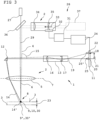
- an autofocus device 26 is shown with an alternatively designed focusing optics 2, which is particularly well suited for use in a laser engraving process.
- the focusing optics 2 has a converging lens 34 , an adjusting lens 35 , the focusing lens 5 and a deflection mirror 36 .
- the adjusting lens 35 is arranged between the focusing lens 5 and a laser light source 37 emitting the processing laser beam 4 in a beam path of the processing laser beam 4 and can be displaced along the beam direction 33 of the processing laser beam 4 by means of the adjusting device 31 .
- Converging lens 34 is designed as a plano-convex lens, adjusting lens 35 as a plano-concave lens, and focusing lens 5 as a bi-convex lens.
- the processing laser beam 4 after exiting the laser light source 37, first passes through the adjusting lens 35, then through the converging lens 34 and then through the focusing lens 5.
- the deflection mirror 36 is between the converging lens 34 and the focusing lens 5 in the beam path of the Processing laser beam 4 arranged.
- the processing laser beam 4 is deflected by the deflection mirror 36 from the converging lens 34 to the focusing lens 5 .
- the focal point 10 of the focusing optics 2 is displaced.
- the deflection mirror 36 is designed as a semi-transparent mirror.
- the pilot laser 27 is arranged above the deflection mirror 36 in such a way that the pilot laser beam 29 runs in the beam path of the processing laser beam 4 after passing through the deflection mirror 36 .
- FIG 4 10 shows a focusing method 38 for focusing a machining laser beam using a detection arrangement according to the invention.
- a target state of the sensor element is first determined in a set-up step 39. The target state is reached when the focal point of the focusing optics is in the impact area of the processing laser.
- the lighting process 40 includes a measuring step 41, a determination step 42 and an adjustment step 43.
- the measuring step 41 of the lighting process 40 it is first determined whether an actual state determined by means of the sensor element corresponds to the target state. If there is a discrepancy between the actual state and the target state, in determination step 42 that follows measuring step 41, the distance between the focal point of the focusing optics and the impact area is determined on the basis of the determined actual state, and the correction value is determined.
- the focusing optics are adjusted by the correction value.
Landscapes
- Physics & Mathematics (AREA)
- Optics & Photonics (AREA)
- Engineering & Computer Science (AREA)
- Plasma & Fusion (AREA)
- Mechanical Engineering (AREA)
- General Physics & Mathematics (AREA)
- Laser Beam Processing (AREA)
- Automatic Focus Adjustment (AREA)
Claims (14)
- Agencement de détection (1) pour surveiller une focalisation d'un faisceau laser d'usinage (4) concentré sur une surface (3) au moyen d'une optique de focalisation (2), l'optique de focalisation (2) présentant au moins une lentille de focalisation (5), à travers laquelle le faisceau laser d'usinage (4) sort de l'optique de focalisation (2) le long d'un axe optique de la lentille de focalisation (6) et un plan principal (7) de la lentille de focalisation (5) étant orienté parallèlement à une section d'éclairage (8) de la surface (3), dans laquelle le faisceau laser d'usinage (4) est incident sur la surface (3) dans une zone d'incidence (9, 9'), le faisceau laser d'usinage (4) étant concentré dans un point focal (10) de l'optique de focalisation (2), et l'agencement de détection (1) présentant au moins un élément capteur (11) et au moins un miroir (12), caractérisé en ce que le miroir (12) est un miroir plan (12), le miroir plan (12) en utilisation avec l'optique de focalisation (2) étant agencé à distance du faisceau laser d'usinage (4), de telle sorte qu'un faisceau de lumière diffusée (14, 14') renvoyé à travers la lentille de focalisation (5) est dévié au moyen du miroir plan (12) dans un plan de détection orienté selon un angle de détection (15) par rapport au faisceau laser d'usinage (4) et orienté vers l'élément capteur (11) agencé dans ce plan de détection.
- Agencement de détection (1) selon la revendication 1, caractérisé en ce que l'agencement de détection (1) présente un laser pilote (27) et/ou peut être mis en liaison active avec un laser pilote (27), un faisceau laser pilote (29) du laser pilote (27) étant incident sur la surface (3) dans une zone d'incidence pilote (30, 30') à l'intérieur de la section d'éclairage (8), le faisceau de lumière diffusée (14, 14') dévié par le miroir (12) provenant du faisceau laser pilote (29), et le laser pilote (27), le faisceau laser d'usinage (4) et l'agencement de détection (1) étant adaptés les uns aux autres et alignés les uns par rapport aux autres de telle sorte qu'une focalisation du faisceau laser d'usinage (4) peut être vérifiée au moyen du faisceau de lumière diffusée (14, 14') du faisceau laser pilote (27), qui est déviée vers l'élément capteur (11).
- Agencement de détection (1) selon l'une quelconque des revendications 1 ou 2, caractérisé en ce que l'agencement de détection (1) présente un objectif (13), le faisceau de lumière diffusée (14, 14') dévié par le miroir (12) pouvant être focalisé sur l'élément capteur (11) au moyen de l'objectif (13), une image extra-axiale d'une zone d'incidence pilote (30, 30') du faisceau laser pilote (29) et/ou de la zone d'incidence (9, 9') du faisceau laser d'usinage (4) dans la section d'éclairage (8) pouvant être projetée sur l'élément capteur (11) au moyen de l'objectif (13).
- Agencement de détection (1) selon l'une quelconque des revendications 1 à 3, caractérisé en ce que l'agencement de détection (1) présente un appareil de traitement de données (24), l'appareil de traitement de données (24) étant mis ou pouvant être mis en liaison active avec l'élément capteur (11) de telle sorte qu'un signal de capteur (25, 25') généré par l'élément capteur (11) peut être évalué au moyen de l'appareil de traitement de données (24).
- Agencement de détection (1) selon la revendication 4, caractérisé en ce qu'une règle est enregistrée dans l'appareil de traitement de données (24), la règle permettant de déterminer, sur la base du signal de capteur (25, 25'), si la focalisation du faisceau laser d'usinage (4) correspond à une valeur de consigne.
- Dispositif de focalisation automatique (26) caractérisé par un agencement de détection (1) selon l'une quelconque des revendications 1 à 5, le dispositif de focalisation automatique (26) présentant un appareil d'ajustement (31), l'appareil d'ajustement (31) étant mis/pouvant être mis en liaison active avec au moins un élément optique de l'optique de focalisation (2) de telle sorte qu'au moyen de l'appareil d'ajustement (31), le point focal (10) de l'optique de focalisation (2) peut être déplacé le long d'une direction de faisceau (33) du faisceau laser d'usinage (4).
- Dispositif de focalisation automatique (26) selon la revendication 6, caractérisé en ce que l'appareil d'ajustement (31) et l'appareil de traitement de données (24) de l'agencement de détection (1) sont mis et/ou peuvent être mis en liaison active l'un avec l'autre de telle sorte que l'optique de focalisation (2) peut être réglée au moyen de l'appareil d'ajustement (31) par l'appareil de traitement de données (24).
- Dispositif de focalisation automatique (26) selon l'une quelconque des revendications 6 ou 7, caractérisé en ce qu'une règle d'évaluation est enregistrée dans l'appareil de traitement de données (24), la règle d'évaluation permettant de déterminer, sur la base du signal de capteur (25, 25'), si le point focal (10) se trouve dans la zone d'incidence (9) du faisceau laser d'usinage (4) ou si la zone d'incidence (9') et le point focal (10) présentent une distance (23) dans, ou à l'encontre de la direction de faisceau (33) du faisceau laser d'usinage, l'un par rapport à l'autre (4) et quelle est la distance (23), une valeur de correction pouvant être déterminée au moyen d'une règle de focalisation enregistrée dans l'appareil de traitement de données (24) sur la base d'un dépôt (21) du signal de capteur (25') et la valeur de correction déterminant la manière dont l'optique de focalisation (2) doit être réglée pour que le point focal (10) puisse être déplacé dans la zone d'incidence (9).
- Dispositif de focalisation automatique (26) selon les revendications 7 et 8, caractérisé en ce qu'une règle d'ajustement est enregistrée dans l'appareil de traitement de données (24), une instruction d'ajustement pouvant être déterminée par l'appareil de traitement de données (24) au moyen de la règle d'ajustement sur la base de la valeur de correction, l'instruction d'ajustement pouvant être transmise à l'appareil d'ajustement (31) et, sur la base de l'instruction d'ajustement, l'optique de focalisation (2) pouvant être réglée au moyen de l'appareil d'ajustement (31) en fonction de la valeur de correction et le point focal (10) pouvant être déplacé dans la zone d'incidence (9) par un réglage de l'optique de focalisation (2) de la valeur de correction.
- Dispositif de focalisation automatique (26) selon l'une quelconque des revendications 6 à 9, caractérisé en ce que l'appareil d'ajustement (31) est mis et/ou peut être mis en liaison active au moins avec la lentille de focalisation (5) de l'optique de focalisation (2), la lentille de focalisation (5) pouvant être déplacée au moyen de l'appareil d'ajustement (31) au moins le long de la direction de faisceau (33) du faisceau laser d'usinage (4) et une position du point focal (10) de l'optique de focalisation (2) pouvant être modifiée au moins par rapport à la surface (3) par un déplacement de la lentille de focalisation (5) au moyen de l'appareil d'ajustement (31).
- Dispositif de focalisation automatique (26) selon l'une quelconque des revendications 6 à 10, caractérisé en ce que l'optique de focalisation (2) présente une lentille d'ajustement (35), la lentille d'ajustement (35) étant agencée entre la lentille de focalisation (5) et une source de lumière laser (37), dans un trajet de faisceau du faisceau laser d'usinage (4) émis par la source de lumière laser (37), l'appareil d'ajustement (31) étant mis en liaison active au moins avec la lentille d'ajustement (35), la lentille d'ajustement (35) pouvant être déplacée au moyen de l'appareil d'ajustement (31) au moins le long de la direction de faisceau (33) du faisceau laser d'usinage (4) et une position du point focal (10) de l'optique de focalisation (2) pouvant être modifiée au moins par rapport à la surface (3) par un déplacement de la lentille d'ajustement (35).
- Dispositif de focalisation automatique (26) selon la revendication 11, caractérisé en ce que l'optique de focalisation (2) présente une lentille convergente (34), la lentille convergente (34) étant configurée sous la forme d'une lentille plan-convexe, la lentille d'ajustement (35) sous la forme d'une lentille plan-concave et la lentille de focalisation (5) sous la forme d'une lentille biconvexe, le faisceau laser d'usinage (4), après une sortie de la source de lumière laser (37), passant d'abord par la lentille d'ajustement (35), puis par la lentille convergente (34) et ensuite par la lentille de focalisation (5), le point focal (10) de l'optique de focalisation (2) pouvant être déplacé le long de la direction de faisceau (33) du faisceau laser d'usinage (4) par un déplacement de la lentille d'ajustement (35) .
- Dispositif de focalisation automatique (26) selon la revendication 12, caractérisé en ce que l'optique de focalisation (2) présente un miroir de déviation (36), le miroir de déviation (36) étant agencé entre la lentille convergente (34) et la lentille de focalisation (5) dans le trajet de faisceau du faisceau laser d'usinage (4), le faisceau laser d'usinage (4) pouvant être dévié par le miroir de déviation (36) d'un angle de déviation de telle sorte qu'il est dévié de la lentille convergente (34) vers la lentille de focalisation (5).
- Procédé de focalisation (38) pour focaliser un faisceau laser d'usinage (4), caractérisé par l'utilisation d'un agencement de détection (1) selon l'une quelconque des revendications 1 à 5, ou par l'utilisation d'un dispositif de focalisation automatique (26) selon l'une quelconque des revendications 6 à 13, un état de consigne de l'élément capteur (11) étant d'abord déterminé dans une étape d'installation (39), l'état de consigne étant atteint lorsque le point focal (10) de l'optique de focalisation (2) se trouve dans la zone d'incidence (9) du faisceau laser d'usinage (4), la surface (3) étant éclairée au moyen du faisceau laser d'usinage (4) dans une opération d'éclairage (40) qui a lieu après l'étape d'installation (39), l'opération d'éclairage (40) comprenant une étape de mesure (41), une étape de détermination (42) et une étape d'ajustement, l'étape de mesure (41) de l'opération d'éclairage (40) déterminant tout d'abord si un état réel déterminé au moyen de l'élément capteur (11) correspond à l'état de consigne, dans le cas d'un décalage (21) entre l'état réel et l'état de consigne, dans une étape de détermination (42) suivant l'étape de mesure (41), sur la base de l'état réel déterminé, la distance (23) du point focal (10) de l'optique de focalisation (2) par rapport à la zone d'incidence (9') étant déterminée au moins le long de la direction de faisceau (33) du faisceau laser d'usinage (4) et la valeur de correction étant déterminée, et dans une étape d'ajustement (43) suivant l'étape de détermination, l'optique de focalisation (2) étant réglée de la valeur de correction.
Applications Claiming Priority (1)
| Application Number | Priority Date | Filing Date | Title |
|---|---|---|---|
| DE102019124671.7A DE102019124671B3 (de) | 2019-09-13 | 2019-09-13 | Detektionsanordnung, Autofokusvorrichtung und Fokussierverfahren |
Publications (3)
| Publication Number | Publication Date |
|---|---|
| EP3799997A1 EP3799997A1 (fr) | 2021-04-07 |
| EP3799997B1 true EP3799997B1 (fr) | 2023-06-07 |
| EP3799997C0 EP3799997C0 (fr) | 2023-06-07 |
Family
ID=72517131
Family Applications (1)
| Application Number | Title | Priority Date | Filing Date |
|---|---|---|---|
| EP20196080.4A Active EP3799997B1 (fr) | 2019-09-13 | 2020-09-14 | Agencement de détection, dispositif de mise au point automatique et procédé de mise au point |
Country Status (3)
| Country | Link |
|---|---|
| EP (1) | EP3799997B1 (fr) |
| DE (1) | DE102019124671B3 (fr) |
| PL (1) | PL3799997T3 (fr) |
Families Citing this family (2)
| Publication number | Priority date | Publication date | Assignee | Title |
|---|---|---|---|---|
| CN115837527A (zh) * | 2023-02-17 | 2023-03-24 | 武汉松盛光电科技有限公司 | 一种激光加工过程中多参量实时监测光学装置及方法 |
| CN118392456B (zh) * | 2024-04-23 | 2024-11-29 | 爱司凯科技股份有限公司 | 实时检测打印焦点漂移的3d打印设备及焦点漂移检测方法 |
Family Cites Families (9)
| Publication number | Priority date | Publication date | Assignee | Title |
|---|---|---|---|---|
| DE2555493A1 (de) * | 1974-12-19 | 1976-06-24 | Gen Electric | Opto-elektronisches geraet zur erfassung der lage und verfahren |
| EP0091400A1 (fr) * | 1982-04-02 | 1983-10-12 | GRETAG Aktiengesellschaft | Procédé et dispositif de focalisation d'un rayon de lumière cohérente |
| JPH03291186A (ja) * | 1990-04-09 | 1991-12-20 | Kiyousera Opt Kk | レーザ加工用光ヘッド |
| JPH0769162B2 (ja) * | 1990-04-23 | 1995-07-26 | 大日本スクリーン製造株式会社 | 光学的検査システムのための自動焦点合わせ装置 |
| JPH09168882A (ja) * | 1995-12-19 | 1997-06-30 | Mitsubishi Chem Corp | レーザテキスチャ装置 |
| JP2005088072A (ja) * | 2003-09-19 | 2005-04-07 | Hitachi Ltd | レーザ加工装置 |
| DE102004020704A1 (de) * | 2004-04-28 | 2005-11-24 | Precitec Kg | Sensorvorrichtung zur Erfassung von Strahlung aus dem Bereich einer Wechselwirkungszone zwischen einem Laserstrahl und einem Werkstück sowie Vorrichtung zur Überwachung eines Laserbearbeitungsvorgangs und Laserbearbeitungskopf |
| DE102010015682B4 (de) * | 2010-04-21 | 2014-01-02 | Peter Arnold | Vorrichtung zum Erfassen der Prozessstrahlung bei der Lasermaterialbearbeitung |
| DE102017115021A1 (de) | 2017-07-05 | 2019-01-10 | Carl Zeiss Microscopy Gmbh | Digitale Bestimmung der Fokusposition |
-
2019
- 2019-09-13 DE DE102019124671.7A patent/DE102019124671B3/de not_active Expired - Fee Related
-
2020
- 2020-09-14 PL PL20196080.4T patent/PL3799997T3/pl unknown
- 2020-09-14 EP EP20196080.4A patent/EP3799997B1/fr active Active
Also Published As
| Publication number | Publication date |
|---|---|
| EP3799997A1 (fr) | 2021-04-07 |
| EP3799997C0 (fr) | 2023-06-07 |
| PL3799997T3 (pl) | 2023-11-27 |
| DE102019124671B3 (de) | 2021-01-14 |
Similar Documents
| Publication | Publication Date | Title |
|---|---|---|
| EP3532238B1 (fr) | Unité de déviation comprenant deux fenêtres, un élément optique et un dispositif de déviation xy | |
| EP3003633B1 (fr) | Dispositif et procédé pour déterminer la position focale d'un faisceau d'énergie à haute densité | |
| EP3583390B1 (fr) | Procédé et dispositif de détection d'une position focale d'un faisceau laser | |
| EP1977850B1 (fr) | Dispositif de traitement de matériau | |
| EP1904260B1 (fr) | Procede et dispositif pour determiner un mouvement relatif lateral entre une tete d'usinage et une piece | |
| DE102011006553A1 (de) | Verfahren zum Ermitteln der Fokuslage eines Laserstrahls in seinem Arbeitsfeld oder Arbeitsraum | |
| DE102013015656A1 (de) | Verfahren zum Messen der Eindringtiefe eines Laserstrahls in ein Werkstück, Verfahren zum Bearbeiten eines Werkstücks sowie Laserbearbeitungsvorrichtung | |
| EP3651931A1 (fr) | Procédé et dispositif pour mesurer et régler un écart entre une tête d'usinage et une pièce | |
| EP3525975A1 (fr) | Procédé et dispositif pour la détermination et la régulation d'une position focale d'un faisceau d'usinage | |
| EP3111161B1 (fr) | Procédé et dispositif de détermination optique d'une distance | |
| DE102013222834A1 (de) | Vorrichtung und Verfahren zur Führung eines Laserstrahls | |
| DE102007048471A1 (de) | Verfahren zum Bestimmen der Lage eines Laserstrahls relativ zu einer Düsenöffnung, Laserbearbeitungsdüse und Laserbearbeitungskopf | |
| DE102014108259A1 (de) | Vorrichtung zur Lasermaterialbearbeitung | |
| DE102020134109B3 (de) | Vorrichtung und Verfahren zur Fokuslagen-Bestimmung | |
| DE102004020704A1 (de) | Sensorvorrichtung zur Erfassung von Strahlung aus dem Bereich einer Wechselwirkungszone zwischen einem Laserstrahl und einem Werkstück sowie Vorrichtung zur Überwachung eines Laserbearbeitungsvorgangs und Laserbearbeitungskopf | |
| DE10160623B4 (de) | Vorrichtung und Verfahren zum Überwachen eines Laserbearbeitungsvorgangs, insbesondere eines Laserschweißvorgangs | |
| DE102022118147A1 (de) | Laserbearbeitungskopf und Verfahren zum Bearbeiten eines Werkstücks | |
| DE102019124671B3 (de) | Detektionsanordnung, Autofokusvorrichtung und Fokussierverfahren | |
| DE102018208752B4 (de) | Vorrichtung und Verfahren zur Bearbeitung zur Bearbeitung schwer zugänglicher Werkstücke sowie Verwendung einer Vorrichtung | |
| DE10056329B4 (de) | Optisches Abstandsmeßverfahren und Abstandssensor | |
| DE102007047298B3 (de) | Verfahren zur Fokuslagenbestimmung und Laserbearbeitungsdüse | |
| EP2147729B1 (fr) | Dispositif de déformation | |
| WO2004029691A1 (fr) | Procede et dispositif pour determiner une distance, module de mise au point automatique, microscope et procede pour la mise au point automatique d'un microscope | |
| EP2767797B1 (fr) | Interféromètre à faible cohérence et procédé de mesure optique à résolution spatiale du profil de surface d'un objet | |
| DE102022101323A1 (de) | Laserschneideverfahren mit Einstellen der Fokuslage |
Legal Events
| Date | Code | Title | Description |
|---|---|---|---|
| PUAI | Public reference made under article 153(3) epc to a published international application that has entered the european phase |
Free format text: ORIGINAL CODE: 0009012 |
|
| STAA | Information on the status of an ep patent application or granted ep patent |
Free format text: STATUS: THE APPLICATION HAS BEEN PUBLISHED |
|
| AK | Designated contracting states |
Kind code of ref document: A1 Designated state(s): AL AT BE BG CH CY CZ DE DK EE ES FI FR GB GR HR HU IE IS IT LI LT LU LV MC MK MT NL NO PL PT RO RS SE SI SK SM TR |
|
| AX | Request for extension of the european patent |
Extension state: BA ME |
|
| STAA | Information on the status of an ep patent application or granted ep patent |
Free format text: STATUS: REQUEST FOR EXAMINATION WAS MADE |
|
| 17P | Request for examination filed |
Effective date: 20211005 |
|
| RBV | Designated contracting states (corrected) |
Designated state(s): AL AT BE BG CH CY CZ DE DK EE ES FI FR GB GR HR HU IE IS IT LI LT LU LV MC MK MT NL NO PL PT RO RS SE SI SK SM TR |
|
| STAA | Information on the status of an ep patent application or granted ep patent |
Free format text: STATUS: EXAMINATION IS IN PROGRESS |
|
| 17Q | First examination report despatched |
Effective date: 20220222 |
|
| GRAP | Despatch of communication of intention to grant a patent |
Free format text: ORIGINAL CODE: EPIDOSNIGR1 |
|
| STAA | Information on the status of an ep patent application or granted ep patent |
Free format text: STATUS: GRANT OF PATENT IS INTENDED |
|
| INTG | Intention to grant announced |
Effective date: 20221213 |
|
| GRAS | Grant fee paid |
Free format text: ORIGINAL CODE: EPIDOSNIGR3 |
|
| GRAA | (expected) grant |
Free format text: ORIGINAL CODE: 0009210 |
|
| STAA | Information on the status of an ep patent application or granted ep patent |
Free format text: STATUS: THE PATENT HAS BEEN GRANTED |
|
| AK | Designated contracting states |
Kind code of ref document: B1 Designated state(s): AL AT BE BG CH CY CZ DE DK EE ES FI FR GB GR HR HU IE IS IT LI LT LU LV MC MK MT NL NO PL PT RO RS SE SI SK SM TR |
|
| REG | Reference to a national code |
Ref country code: GB Ref legal event code: FG4D Free format text: NOT ENGLISH |
|
| REG | Reference to a national code |
Ref country code: CH Ref legal event code: EP Ref country code: AT Ref legal event code: REF Ref document number: 1573516 Country of ref document: AT Kind code of ref document: T Effective date: 20230615 |
|
| REG | Reference to a national code |
Ref country code: DE Ref legal event code: R096 Ref document number: 502020003536 Country of ref document: DE |
|
| U01 | Request for unitary effect filed |
Effective date: 20230704 |
|
| U07 | Unitary effect registered |
Designated state(s): AT BE BG DE DK EE FI FR IT LT LU LV MT NL PT SE SI Effective date: 20230727 |
|
| REG | Reference to a national code |
Ref country code: LT Ref legal event code: MG9D |
|
| U20 | Renewal fee for the european patent with unitary effect paid |
Year of fee payment: 4 Effective date: 20230913 |
|
| PG25 | Lapsed in a contracting state [announced via postgrant information from national office to epo] |
Ref country code: NO Free format text: LAPSE BECAUSE OF FAILURE TO SUBMIT A TRANSLATION OF THE DESCRIPTION OR TO PAY THE FEE WITHIN THE PRESCRIBED TIME-LIMIT Effective date: 20230907 Ref country code: ES Free format text: LAPSE BECAUSE OF FAILURE TO SUBMIT A TRANSLATION OF THE DESCRIPTION OR TO PAY THE FEE WITHIN THE PRESCRIBED TIME-LIMIT Effective date: 20230607 |
|
| PG25 | Lapsed in a contracting state [announced via postgrant information from national office to epo] |
Ref country code: RS Free format text: LAPSE BECAUSE OF FAILURE TO SUBMIT A TRANSLATION OF THE DESCRIPTION OR TO PAY THE FEE WITHIN THE PRESCRIBED TIME-LIMIT Effective date: 20230607 Ref country code: HR Free format text: LAPSE BECAUSE OF FAILURE TO SUBMIT A TRANSLATION OF THE DESCRIPTION OR TO PAY THE FEE WITHIN THE PRESCRIBED TIME-LIMIT Effective date: 20230607 Ref country code: GR Free format text: LAPSE BECAUSE OF FAILURE TO SUBMIT A TRANSLATION OF THE DESCRIPTION OR TO PAY THE FEE WITHIN THE PRESCRIBED TIME-LIMIT Effective date: 20230908 |
|
| PG25 | Lapsed in a contracting state [announced via postgrant information from national office to epo] |
Ref country code: SK Free format text: LAPSE BECAUSE OF FAILURE TO SUBMIT A TRANSLATION OF THE DESCRIPTION OR TO PAY THE FEE WITHIN THE PRESCRIBED TIME-LIMIT Effective date: 20230607 |
|
| PG25 | Lapsed in a contracting state [announced via postgrant information from national office to epo] |
Ref country code: IS Free format text: LAPSE BECAUSE OF FAILURE TO SUBMIT A TRANSLATION OF THE DESCRIPTION OR TO PAY THE FEE WITHIN THE PRESCRIBED TIME-LIMIT Effective date: 20231007 |
|
| PG25 | Lapsed in a contracting state [announced via postgrant information from national office to epo] |
Ref country code: SM Free format text: LAPSE BECAUSE OF FAILURE TO SUBMIT A TRANSLATION OF THE DESCRIPTION OR TO PAY THE FEE WITHIN THE PRESCRIBED TIME-LIMIT Effective date: 20230607 Ref country code: SK Free format text: LAPSE BECAUSE OF FAILURE TO SUBMIT A TRANSLATION OF THE DESCRIPTION OR TO PAY THE FEE WITHIN THE PRESCRIBED TIME-LIMIT Effective date: 20230607 Ref country code: RO Free format text: LAPSE BECAUSE OF FAILURE TO SUBMIT A TRANSLATION OF THE DESCRIPTION OR TO PAY THE FEE WITHIN THE PRESCRIBED TIME-LIMIT Effective date: 20230607 Ref country code: IS Free format text: LAPSE BECAUSE OF FAILURE TO SUBMIT A TRANSLATION OF THE DESCRIPTION OR TO PAY THE FEE WITHIN THE PRESCRIBED TIME-LIMIT Effective date: 20231007 Ref country code: CZ Free format text: LAPSE BECAUSE OF FAILURE TO SUBMIT A TRANSLATION OF THE DESCRIPTION OR TO PAY THE FEE WITHIN THE PRESCRIBED TIME-LIMIT Effective date: 20230607 |
|
| REG | Reference to a national code |
Ref country code: DE Ref legal event code: R097 Ref document number: 502020003536 Country of ref document: DE |
|
| PLBE | No opposition filed within time limit |
Free format text: ORIGINAL CODE: 0009261 |
|
| STAA | Information on the status of an ep patent application or granted ep patent |
Free format text: STATUS: NO OPPOSITION FILED WITHIN TIME LIMIT |
|
| REG | Reference to a national code |
Ref country code: CH Ref legal event code: PL |
|
| 26N | No opposition filed |
Effective date: 20240308 |
|
| PG25 | Lapsed in a contracting state [announced via postgrant information from national office to epo] |
Ref country code: MC Free format text: LAPSE BECAUSE OF FAILURE TO SUBMIT A TRANSLATION OF THE DESCRIPTION OR TO PAY THE FEE WITHIN THE PRESCRIBED TIME-LIMIT Effective date: 20230607 |
|
| REG | Reference to a national code |
Ref country code: IE Ref legal event code: MM4A |
|
| PG25 | Lapsed in a contracting state [announced via postgrant information from national office to epo] |
Ref country code: IE Free format text: LAPSE BECAUSE OF NON-PAYMENT OF DUE FEES Effective date: 20230914 |
|
| PG25 | Lapsed in a contracting state [announced via postgrant information from national office to epo] |
Ref country code: CH Free format text: LAPSE BECAUSE OF NON-PAYMENT OF DUE FEES Effective date: 20230930 |
|
| PG25 | Lapsed in a contracting state [announced via postgrant information from national office to epo] |
Ref country code: IE Free format text: LAPSE BECAUSE OF NON-PAYMENT OF DUE FEES Effective date: 20230914 Ref country code: CH Free format text: LAPSE BECAUSE OF NON-PAYMENT OF DUE FEES Effective date: 20230930 |
|
| U20 | Renewal fee for the european patent with unitary effect paid |
Year of fee payment: 5 Effective date: 20240925 |
|
| PG25 | Lapsed in a contracting state [announced via postgrant information from national office to epo] |
Ref country code: CY Free format text: LAPSE BECAUSE OF FAILURE TO SUBMIT A TRANSLATION OF THE DESCRIPTION OR TO PAY THE FEE WITHIN THE PRESCRIBED TIME-LIMIT; INVALID AB INITIO Effective date: 20200914 |
|
| PG25 | Lapsed in a contracting state [announced via postgrant information from national office to epo] |
Ref country code: HU Free format text: LAPSE BECAUSE OF FAILURE TO SUBMIT A TRANSLATION OF THE DESCRIPTION OR TO PAY THE FEE WITHIN THE PRESCRIBED TIME-LIMIT; INVALID AB INITIO Effective date: 20200914 |
|
| U20 | Renewal fee for the european patent with unitary effect paid |
Year of fee payment: 6 Effective date: 20250820 |
|
| PGFP | Annual fee paid to national office [announced via postgrant information from national office to epo] |
Ref country code: PL Payment date: 20250904 Year of fee payment: 6 |
|
| PGFP | Annual fee paid to national office [announced via postgrant information from national office to epo] |
Ref country code: GB Payment date: 20250923 Year of fee payment: 6 |
|
| PG25 | Lapsed in a contracting state [announced via postgrant information from national office to epo] |
Ref country code: TR Free format text: LAPSE BECAUSE OF FAILURE TO SUBMIT A TRANSLATION OF THE DESCRIPTION OR TO PAY THE FEE WITHIN THE PRESCRIBED TIME-LIMIT Effective date: 20230607 |