EP3800317A1 - Fenêtre dotée d'un conduit d'aération - Google Patents
Fenêtre dotée d'un conduit d'aération Download PDFInfo
- Publication number
- EP3800317A1 EP3800317A1 EP20199701.2A EP20199701A EP3800317A1 EP 3800317 A1 EP3800317 A1 EP 3800317A1 EP 20199701 A EP20199701 A EP 20199701A EP 3800317 A1 EP3800317 A1 EP 3800317A1
- Authority
- EP
- European Patent Office
- Prior art keywords
- frame
- ventilation
- sash
- window
- ventilation duct
- Prior art date
- Legal status (The legal status is an assumption and is not a legal conclusion. Google has not performed a legal analysis and makes no representation as to the accuracy of the status listed.)
- Granted
Links
Images


Classifications
-
- E—FIXED CONSTRUCTIONS
- E06—DOORS, WINDOWS, SHUTTERS, OR ROLLER BLINDS IN GENERAL; LADDERS
- E06B—FIXED OR MOVABLE CLOSURES FOR OPENINGS IN BUILDINGS, VEHICLES, FENCES OR LIKE ENCLOSURES IN GENERAL, e.g. DOORS, WINDOWS, BLINDS, GATES
- E06B7/00—Special arrangements or measures in connection with doors or windows
- E06B7/02—Special arrangements or measures in connection with doors or windows for providing ventilation, e.g. through double windows; Arrangement of ventilation roses
- E06B7/10—Special arrangements or measures in connection with doors or windows for providing ventilation, e.g. through double windows; Arrangement of ventilation roses by special construction of the frame members
-
- E—FIXED CONSTRUCTIONS
- E06—DOORS, WINDOWS, SHUTTERS, OR ROLLER BLINDS IN GENERAL; LADDERS
- E06B—FIXED OR MOVABLE CLOSURES FOR OPENINGS IN BUILDINGS, VEHICLES, FENCES OR LIKE ENCLOSURES IN GENERAL, e.g. DOORS, WINDOWS, BLINDS, GATES
- E06B3/00—Window sashes, door leaves, or like elements for closing wall or like openings; Layout of fixed or moving closures, e.g. windows in wall or like openings; Features of rigidly-mounted outer frames relating to the mounting of wing frames
- E06B3/04—Wing frames not characterised by the manner of movement
- E06B3/06—Single frames
- E06B3/08—Constructions depending on the use of specified materials
- E06B3/20—Constructions depending on the use of specified materials of plastics
- E06B3/22—Hollow frames
- E06B3/221—Hollow frames with the frame member having local reinforcements in some parts of its cross-section or with a filled cavity
-
- E—FIXED CONSTRUCTIONS
- E06—DOORS, WINDOWS, SHUTTERS, OR ROLLER BLINDS IN GENERAL; LADDERS
- E06B—FIXED OR MOVABLE CLOSURES FOR OPENINGS IN BUILDINGS, VEHICLES, FENCES OR LIKE ENCLOSURES IN GENERAL, e.g. DOORS, WINDOWS, BLINDS, GATES
- E06B7/00—Special arrangements or measures in connection with doors or windows
- E06B7/02—Special arrangements or measures in connection with doors or windows for providing ventilation, e.g. through double windows; Arrangement of ventilation roses
- E06B7/04—Special arrangements or measures in connection with doors or windows for providing ventilation, e.g. through double windows; Arrangement of ventilation roses with ventilation wings
- E06B7/06—Special arrangements or measures in connection with doors or windows for providing ventilation, e.g. through double windows; Arrangement of ventilation roses with ventilation wings with one ventilation wing only
-
- E—FIXED CONSTRUCTIONS
- E06—DOORS, WINDOWS, SHUTTERS, OR ROLLER BLINDS IN GENERAL; LADDERS
- E06B—FIXED OR MOVABLE CLOSURES FOR OPENINGS IN BUILDINGS, VEHICLES, FENCES OR LIKE ENCLOSURES IN GENERAL, e.g. DOORS, WINDOWS, BLINDS, GATES
- E06B3/00—Window sashes, door leaves, or like elements for closing wall or like openings; Layout of fixed or moving closures, e.g. windows in wall or like openings; Features of rigidly-mounted outer frames relating to the mounting of wing frames
- E06B3/04—Wing frames not characterised by the manner of movement
- E06B3/06—Single frames
- E06B3/08—Constructions depending on the use of specified materials
- E06B3/20—Constructions depending on the use of specified materials of plastics
- E06B3/22—Hollow frames
- E06B3/221—Hollow frames with the frame member having local reinforcements in some parts of its cross-section or with a filled cavity
- E06B2003/228—Hollow frames with the frame member having local reinforcements in some parts of its cross-section or with a filled cavity with separate reinforcements situated outside the cavity or in the walls
Definitions
- the invention relates to a window with a ventilation duct according to the preamble of claim 1.
- Such a window which enables sound-insulated ventilation in a tilted or rotated sash position, is known per se, for example from US Pat DE 10 2016 115 422 .
- the generic construction has a relatively complicated structure and should therefore be further optimized in this regard and, according to variants, also with regard to various other properties.
- a window is created, in particular a tilt window, turn window or turn-tilt window or parallel opening window, which has at least the following features: a frame composed of several frame profiles, a casement frame composed of several frame profiles, which has at least one surface element and at least between a closed position and a ventilation position is movable relative to the frame, wherein a circumferential frame rebate space is formed between the frame profiles of the frame and the sash, at least one in at least one of the frame profiles of the frame or in at least one of the frame profiles of the sash formed ventilation channel, the first Having a ventilation duct opening and a second ventilation duct opening, and wherein the casement and the frame are designed to close at least one of the ventilation duct openings in the first closed position, and in the two th position to release both ventilation duct openings of the at least one ventilation duct.
- At least the at least one frame profile of the window frame or the sash, in which the at least one ventilation duct is formed is designed as a multi-chamber hollow profile that consists entirely or essentially entirely of plastic, in particular the adjacent spaces of the window Walls are made of plastic.
- Plastic frame profiles for example made of hard PVC, are significantly cheaper than aluminum composite structures.
- PVC profiles in particular have excellent thermal properties and are also suitable for passive houses if they are appropriately designed with enough hollow chambers interpretable.
- the "multi-chamber structure” can also ensure very good statics in configurations without reinforcement reinforcement and / or without a reinforcement insert.
- Partition walls can then be formed or arranged much more easily in plastic profiles than in aluminum profiles.
- Several hollow chambers are advantageous for sound insulation.
- An advantageous mass-spring-mass system is formed, with the profile walls forming the mass and the air lying between the walls forming the respective spring in the present case.
- the profile outer walls can have thicker walls, preferably 2-4 mm.
- the inner profile walls can only be relatively thin, e.g. 1 - 2 mm. This is beneficial as it does a good job of soundproofing and thermal insulation.
- Another particularly preferred frame profile, in which the ventilation duct can be formed has hollow chambers of different sizes with inclined partition walls - that is, non-parallel partition walls.
- the walls are preferably constructed asymmetrically.
- the points of attachment of the partition walls to other walls - e.g. one or more external walls - are then at different distances from one another. As a result, standing sound waves interfere destructively. Vibrations decrease.
- Frame profiles whose material has a thermal conductivity of less than 1.0 W / mK are preferably used. This is also advantageous as it makes a good contribution to thermal insulation.
- all of the multi-chamber profiles of the window frame and / or the sash frame consist entirely or essentially entirely of plastic.
- one or more of the multi-chamber hollow profiles made of plastic of the window frame and / or the casement have at least one reinforcement insert.
- the reinforcement insert can be designed as a metal profile, for example as a tube. It is advantageous if steel pipes, e.g. square pipes, are simply pushed into the PVC profiles and screwed as reinforcement inserts.
- a reinforcement reinforcement e.g. made of metal, is made in coextrusion with the multi-chamber hollow profile made of plastic.
- a design with a coextruded reinforcement reinforcement is particularly advantageous. No additional assembly steps are required here. Only a recess in the rebate of the profile for the use of a ventilation cassette may be required. The ventilation cassette is simply clipped into the recess and / or fixed with screws.
- At least two sealing levels are formed between the frame and the casement in the area of the frame rebate space.
- At least a first of the sealing planes is formed between the frame and the casement in the area of the frame rebate space in the open state. It can also be advantageously and simply provided that two of the sealing planes are formed by stop seals between the frame and the casement.
- one of the sealing planes of a central seal between the frame and the casement is formed. It is preferred that the central seal is designed to form the sealing plane remaining in the frame rebate space in the ventilation position and to subdivide the frame rebate space into two frame rebate space sections so that air in the ventilation position between the two frame rebate space sections can essentially only be exchanged through the ventilation duct.
- center seal is attached to the frame and is in particular in the ventilation position in contact with the sash.
- center seal is attached to the casement and, in particular, is in contact with the frame in the ventilation position.
- the center seal can be made in one piece with the "sliding seal” or separately from one another.
- the heat transfer, sound insulation and tightness (air / moisture) are optimized by the three sealing levels.
- seals are preferably used in each case, which are inserted and held in retaining grooves.
- Such seals are relatively inexpensive and, above all, easy to assemble. They can be laid all around without having to be cut in the corners. Due to the arrangement in retaining grooves, the seals can be easily replaced.
- the seals can preferably also be welded to one another.
- the stop seals (inside / outside) and the center seal are preferably designed circumferentially, i.e. on four sides of the frame, while the sliding seal / sliding sealing lip (separate or integral with the center seal) only on one side (opposite the tilting axis) or preferably on three sides (except on the tilt axis) is arranged.
- the center seal can preferably be designed as a lip seal with one or more sealing lips, each of which is relatively thin and flexible.
- a large-volume, multi-chamber central seal is advantageously not necessary in this way.
- the seals are advantageously made from a weldable TPE or weldable EPDM. In this way, profiles with inserted seals can be welded to form a frame at the same time.
- the sliding seal is multi-articulated and has a curved sliding surface which, together with the sliding strip attached to the frame, forms a particularly favorable friction pairing.
- the surface structures and the material combination are important to achieve an optimal result.
- the relatively small opening width results in the aforementioned prior art through the closure means, the insulating web.
- This has only a limited length.
- the sliding sealing lip closes the gap between the frame and the sash up to the outer profile edge of the sash profile. This results in a larger opening width ("W").
- W opening width
- B profile width
- 50 to 80 mm are preferably achieved.
- the geometry of the sliding seal, in particular the length of the sealing lip, is also decisive. Overall, therefore, even greater widths are possible.
- a width of 55 to 65 mm is particularly preferred.
- a significantly larger number of hollow chambers has a beneficial effect on sound insulation.
- the central seal has a seal base and a sealing section that is pivotably attached to the seal base.
- This is preferably designed as a pivotable sealing lip.
- the sealing section - in particular the sealing lip - can be connected to the sealing base in an articulated manner.
- the sealing section rests at its free end with a contact sliding section on the frame or on the casement in any case in the area or areas in which a respective ventilation duct is formed. It can then be further provided that the contact sliding section rests against a sliding strip in the ventilation position and thus subdivides the frame rebate space in a sealing manner.
- a contact sliding section and / or a sliding strip By using a contact sliding section and / or a sliding strip, the friction of the sliding seal on the casement can be reduced.
- This means material and Surface structures are adapted to each other.
- the sliding seal preferably has a roughened surface structure on the sliding side.
- the sliding strip is preferably characterized by a sliding coating.
- the surface structure can of course also be designed the other way around.
- the contact sliding section has a roughened surface structure on the sliding side and / or that the sliding strip has a sliding coating or that the sliding strip has a roughened surface structure on the sliding side and / or that the contact sliding section has a sliding coating.
- the one or more ventilation ducts is / are each formed in a ventilation cassette, which is / are in the frame or sash or . is / are inserted into the respective frame profile or the respective sash profile.
- the formation of the ventilation duct is significantly simplified because it does not have to be laboriously formed directly in the hollow chamber profiles. Rather, it is sufficient to provide or form a recess there and then insert the preassembled ventilation cassette into the recess, e.g. to snap it into place or clamp it.
- the respective ventilation cassette can be inserted in a simple manner and preferably not visible to the outside in the closed position into a recess of the respective frame profile or of the respective sash profile facing the frame rebate space.
- the respective ventilation cassette has the ventilation duct openings and that these are aligned with the frame rebate space. It can particularly advantageously be provided that the ventilation duct openings in the closed state lie completely in the frame rebate space between the stop seals. This does not change the external appearance of the window. The preferred design remains.
- the ventilation cassettes can be changed very easily in this way. This is required approximately annually in order to meet the requirements for purity (dust, insects, etc.). No specialist is required to replace them.
- the frame profiles, apart from the reinforcement reinforcements, can be formed from a plastic that has a thermal conductivity of less than 1.0 W / mK.
- the sash when it is moved from the closed position into the ventilation position, can be moved at least at one point by 50 to 80 mm relative to the frame.
- the air exchange at 2 PA can be more than 12 m 3 / h (preferably> 14), at 10 PA> 25 m 3 / h (preferably> 28).
- Synthetic microfibers that are able to filter pollen are preferably arranged in the ventilation cassettes. This is of particular benefit to allergy sufferers.
- the invention also creates an advantageous method for forming a ventilation duct in a window according to one or more of the claims related thereto, a window frame profile being provided, with a recess facing the frame rebate then being formed in the respective window frame profile in which a ventilation duct is to be formed and that a ventilation cassette is inserted exchangeably in the respective recess of the respective frame profile or of the respective sash profile facing the frame rebate space.
- a corresponding, corresponding sash can then be inserted into the mounted frame at the place of use after installation in a building opening.
- the center seal can after the assembly of the ventilation cassette on this and on the rest Frame can be mounted. When changing, it is simply removed again. It is particularly advantageous in each case that the assembly can generally be carried out by an insertion movement parallel to the plane of the pane, which is simple and convenient.
- this cassette can simply be cleaned and / or changed after opening the window, for example after one or more years.
- the ventilation cassette can be fixed to the frame in the most varied of ways, in a clamping manner or preferably with a fastening means such as at least one screw. It is also conceivable to change a filter material in the ventilation cassette if the ventilation cassette is provided with such a material.
- the center seal and the ventilation cassette can also be viewed as separate inventions.
- the central seal for a window according to one of the related claims then has one or more of the features directed to the central seal in the preceding claims and / or the ventilation cassette for a window according to one of the preceding claims has one or more of the claims features directed towards the ventilation cassette.
- the center seal and the ventilation cassette can alternatively be used to advantage on frames made of metal profiles or composite profiles (e.g. aluminum profile outside, plastic insulating bar inside and again aluminum profile outside).
- the advantageous sliding strip with one or more of its features disclosed in this description can then also be used on the wing.
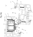
- Fig. 1 shows a portion of a window.
- This window has a peripheral frame 1. This is composed of several frame profiles 1 '.
- the sash On the frame 1 a relative to the frame 1 movable sash is arranged.
- the sash preferably has a circumferentially closed sash frame 2 and a surface element 3, such as a pane, inserted into the sash frame 2 and received by it.
- the sash frame 2 is composed of several sash frame profiles 2 '.
- the frame profiles 1 'and / or the sash profile 2' are designed as multi-chamber hollow profiles.
- a preferably circumferential frame rebate space F is formed between the frame 1 and the casement 2 or their frame profiles 1 ', 2'.
- This frame rebate space F essentially extends between the outer circumference of the casement 2 and the inner circumference of the window frame 1.
- the window is used to be able to close and open a room opening of a building (not shown here), whereby a room I (e.g. an area surrounding a building) is separated from a room II (e.g. an interior of the building).
- a room I e.g. an area surrounding a building
- a room II e.g. an interior of the building
- frame profile 1 ' and “frame 1” as well as “sash profile 2'” and “sash 2” are each used synonymously.
- the means and configurations discussed below can each preferably be formed circumferentially on the frame 1 or the casement 2. They can only be formed on one of the corresponding frame profiles of the casement 2 and the window frame 1 (e.g. on the frame profiles opposite a hinge axis) or on several of the corresponding frame profiles of the casement 2 and the window frame 1.
- Running sides of the window frame also form corresponding gaps in the ventilation position, but these gaps do not have a constant width when they are pivoted open. Nevertheless, in addition to improving the ventilation effect, especially on these sides, ventilation ducts 8 of the type can also be used Fig. 1a and 1b also be trained.
- the sash frame 2 can - preferably to one side or to an adjoining room II - have a contact web 4 with which it rests in the closed position on the frame 1 directly or via a stop seal 5 attached to the sash frame 2.
- the frame 1 can have a contact web 6 in which it rests in the closed position on the window frame 1 directly or via a stop seal 7 attached to the contact web 6. In this way, a gap SII and a gap SI between the frame rebate space F and the space I or II are tightly closed.
- a ventilation duct 8 (dashed lines) is formed, which has a first ventilation duct opening 9 and a second ventilation duct opening 10. It is preferably provided that the ventilation duct openings 9 and 10 open into the frame rebate space F.
- the ventilation duct 8 can have a U-shape.
- At least the hollow profile or profiles of the window frame 1 or the sash frame 2, in which the ventilation duct 8 is formed are formed as multi-chamber hollow profiles made of plastic.
- These multi-chamber hollow profiles made of plastic preferably have three or more hollow chambers H1, H2, ... between the room side I and the room II.
- seven hollow chambers H1 to H7 are provided between space I and space II ("from inside to outside").
- Further hollow chambers can also be formed perpendicular to the direction I-II, in particular in the area of the contact webs.
- One or more further hollow chambers H8, H9, H10, H11 can also be provided.
- One or more of these further hollow chambers H8, H9 can advantageously be provided in the respective contact web 4 or 6. These measures improve the soundproofing and the thermal insulation, either each or together.
- all the hollow profiles of the window frame 1 or the sash frame 2 are designed as multi-chamber hollow profiles made of plastic.
- the plastic is particularly preferably a PVC.
- one or more of the multi-chamber hollow profiles made of plastic of the window frame 1 and / or one or more of the multi-chamber hollow profiles made of plastic of the sash 2 has / have at least one reinforcement reinforcement 11, 12 or several reinforcement reinforcements 11, 12.
- the respective reinforcing reinforcement 11, 12 can consist of a different material than the multi-chamber hollow profile made of plastic, for example a metal, in particular steel and a metal profile, for example a metal strip or metal plate or the like. However, it can also be designed as reinforcement reinforcement made from another plastic, for example from a glass fiber reinforced plastic.
- the multi-chamber profiles then preferably have a continuous plastic outer wall towards a first room side I and preferably have a continuous plastic outer wall towards a second room side II.
- the ventilation duct 8 is formed in a recess 13, in particular in a milled recess that is formed in the frame 1 or the casement 2 starting from the frame rebate space.
- the ventilation duct 8 is formed in a ventilation cassette 14 which is inserted into the recess 13, in particular into the cutout - in the frame 1 or the casement 2.
- Several of these ventilation cassettes 14 can also be provided per frame profile or on several sides of the frame (not shown).
- the ventilation duct 8 can thus be formed simply in only one or in several of the profiles of the surrounding window frame 1 or of the sash frame 2.
- the respective ventilation cassette 14 has a channel-like or trough-like base element 15. It can also be provided that the respective ventilation cassette 14 has a cover 16.
- the cover 16 is preferably directed towards the frame rebate area F.
- the center seal 18 can be attached to the ventilation cassette 14, in particular to the cover 16.
- a fastening means, in particular an undercut groove 17, is designed for the central seal 18.
- the center seal 18 may have a seal base 20 with a seal foot 21 inserted into the groove.
- the seal 18 can furthermore have a sealing section 22 which is fastened pivotably on the seal base 20.
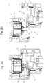
- This can be designed as a single sealing lip ( Fig.1a and 1b ) or as a combination of two or more sealing lips ( Figures 2a and b ).
- the sealing section 22 can in particular have a sealing lip which is designed to be curved in itself and / or again has a hinge section so that it is divided into two lip areas that are movable relative to one another and that connect to form a longer lip.
- sealing section 22 can be pivoted relative to the sealing base 21 and that it is so long that it can be in contact with the sash frame 2. There it is preferably on with an end section. This end section can be arcuate.
- the sealing section 22 can have an abutment sliding section 23 as an end section, which rests on the corresponding frame profile, here the sash profile, during relative movements between the frame 1 and the sash frame 2 and can slide well. This results in a harmonious, easy opening movement that is not significantly hindered by the adjacent sealing surface.
- the contact sliding section 23 is preferably provided on the center seal where a ventilation duct 8 is also provided in the respective frame profile. This can be on one side of the window frame 1 or casement 2 or on several sides, preferably on three sides. If it is a tilt window, preferably no ventilation duct is formed on the side on which the tilt axis is located.
- the contact sliding section 23 can be dispensed with here.
- the sealing section 22 is preferably so long that it initially remains in contact with the sash frame 2 over a certain opening angle when the sash is opened, or at least in one
- the ventilation position still to be explained is or comes into contact with the sash frame 2, so that it divides the frame rebate space F in the ventilation position into two areas, between which an exchange of air essentially only takes place via the ventilation duct 8.
- the center seal 18 thus divides the frame rebate space F into a first and a second area FI, FII (corresponding to the orientation to the spaces I and II), between which an exchange of air is only possible via the ventilation duct 8 formed in the frame 1.
- the center seal is attached to the sash frame 2 and extends as far as the frame 1 (see Fig Fig. 3 ).
- the sealing section 22 should preferably be long enough that, when the sash is opened, it initially remains in contact with the window frame 1 over a certain opening angle, or is or comes into contact with the window frame 1 in a ventilation position to be explained below, so that it divides the frame rebate space F in the ventilation position into two areas, between which an exchange of air essentially only takes place via the ventilation duct 8.
- the sash was moved into an open position relative to the frame 1, in particular pivoted and / or shifted.
- This open position is a ventilation position. It can - but this is not mandatory - correspond to the maximum attainable position when tilting or rotating or the like.
- the column SI and SII are open in this position, since the stop seals 5 and 7 are no longer in contact with the frame 1 or sash frame 2.
- the center seal 18 is still in contact with the sash frame 2.
- the sash is still partially within the scope defined by the frame 2.
- There the central seal 18 blocks the direct transition between the rooms FI and FII, an exchange of air between these rooms FI and FII and thus also an exchange of air between the rooms I and II can only take place through the ventilation duct. This provides a very advantageous combination of a ventilation and a sound insulation effect.
- air can flow into interior space I through gap SI, frame rebate space section FI, ventilation duct 8, frame rebate space section FII and gap SII.
- the sound is advantageously insulated, in particular, by deflecting the direction of the ventilation duct.
- the air flowing through should therefore preferably have to change direction once or several times within the ventilation duct. This has a beneficial effect on the sound insulation.
- the ventilation duct 8 has the first ventilation duct opening 9 and the second ventilation duct opening 10. These two ventilation duct openings 9, 10 can be formed in the ventilation cassette 14. The two ventilation duct openings 9, 10 are preferably formed in the cover 16.
- both ventilation duct openings 9, 10 are oriented towards the frame rebate space F.
- At least one wall 19 can be formed inside the ventilation cassette 14 which divides the ventilation cassette interior into sections. This wall 19 can have at least one passage 19a. One of the ventilation duct openings 9, 10 is then located in one of the sections.
- the ventilation duct 8 runs in an approximately U-shape within the ventilation cassette 14 (or even without a ventilation cassette). It extends from the first ventilation duct opening 9 approximately parallel to the surface element 3 into the ventilation cassette 14, then runs approximately perpendicular to the surface element 3, extends there through the passage 19a of the wall 19 and runs approximately again parallel to the surface element up to the ventilation duct opening 10. In this way, the direction of air flowing through changes several times. This insulates or prevents the passage of sound from room I to room II and vice versa. Nevertheless, an air flow for ventilation can pass from room I to room II.
- a sliding strip 24 is arranged on the sash frame 2 or on its sash frame profiles 2 ', on which a ventilation duct 8 is also provided. The center seal 18 can then rest against this in the ventilation position L.
- the sliding strip 24 is provided relatively far to the side and / or in a corner area of the respective casement profile 2 '.
- This corner area is preferably that corner area which is closest to the corresponding frame profile 1 'in the opening and ventilation position.
- the sliding strip can lie laterally outside an area that is defined by the inner and outer edge plane of the insulating glass pane,
- the slide bar 24 can be made of metal or some other material such as plastic. They also have at least one hollow chamber themselves.
- the sliding strip 24 can also advantageously be designed as an extension strip which is fixed to the respective sash profile 2 'with a fastening, for example a tongue and groove connection.
- the frame profiles are made of a plastic material, preferably PVC. They are preferably made entirely of plastic - possibly with the exception of internal reinforcement profiles or reinforcement reinforcements. They can be made in one piece, especially if they are made of plastic.
- the outer walls of the hollow chamber profiles made of plastic preferably have a thickness of 2-4 mm, while the thickness of the partition walls forming hollow chambers H1-H7 can be 1-2 mm.
- further reinforcement reinforcements 10, 11 made of metal are optionally arranged in the hollow chambers for static reinforcement and further subdivide them.
- Particularly preferred frame profiles 1 ', 2' are those with embedded reinforcement profiles which are manufactured by a coextrusion process, the reinforcement reinforcements being made of aluminum or fiber-reinforced plastic.
- stop seals (inside / outside) 5, 7 and the center seal 18 are designed circumferentially, that is, run on four sides of the frame, while the sealing section is not provided on all sides of the frame.
- the seals - here you seals 5, 7, 18 - can advantageously be made from a weldable TPE or weldable EPDM. In this way, profiles with inserted seals can be welded to form a frame at the same time.
- the center seal with the contact sliding section 23 is multi-articulated and has a curved sliding surface which, together with a sliding strip 24 attached to the sash frame (or frame 1), forms a particularly favorable friction pairing.
- the surface structures and the material combination are important to achieve an optimal result.
- the contact sliding section 23 closes the frame rebate space or gap between the frame and the sash up to the outer profile edge of the sash frame 2.
- W opening width
- B profile width
- 50 to 80 mm are preferably achieved.
- the geometry of the sliding seal, in particular the length of the sealing lip, is also advantageous. Overall, such relatively large opening widths can be achieved in the ventilation position. A width of 55 to 65 mm is particularly preferred.
- Wmax. B - 25 mm.
- a significantly larger number of hollow chambers compared to an aluminum composite structure has an advantageous effect in terms of sound insulation.
- the sliding strip 24 By using the sliding strip 24, the friction of the sliding seal on the casement can be reduced to a minimum.
- the sliding seal preferably has a roughened surface structure on the sliding side.
- the sliding strip is preferably characterized by a sliding coating.
- the surface structure can of course also be designed the other way around.
- the inner chamber H7 is preferably not used directly as a ventilation duct, since this is not advantageous for reasons of sound insulation. Rather, two chambers can form between the ventilation cassette wall and the outside, which chambers are particularly preferably separated from one another by an aluminum wall.
- FIG. 2a and b is complementary to the construction of the Fig. 1a and b provided to form a further sealing lip 25 on the center seal 18 on the sealing base 20, which in the closed state rests on the sash frame 2, so that even sections of four sealing planes are advantageously formed in the frame rebate space between the frame and the sash frame.
Landscapes
- Engineering & Computer Science (AREA)
- Civil Engineering (AREA)
- Structural Engineering (AREA)
- Specific Sealing Or Ventilating Devices For Doors And Windows (AREA)
Applications Claiming Priority (2)
| Application Number | Priority Date | Filing Date | Title |
|---|---|---|---|
| DE102019126756 | 2019-10-04 | ||
| DE102020106694.5A DE102020106694A1 (de) | 2019-10-04 | 2020-03-11 | Fenster mit einem Lüftungskanal |
Publications (2)
| Publication Number | Publication Date |
|---|---|
| EP3800317A1 true EP3800317A1 (fr) | 2021-04-07 |
| EP3800317B1 EP3800317B1 (fr) | 2025-08-06 |
Family
ID=72717817
Family Applications (1)
| Application Number | Title | Priority Date | Filing Date |
|---|---|---|---|
| EP20199701.2A Active EP3800317B1 (fr) | 2019-10-04 | 2020-10-01 | Fenêtre dotée d'un conduit d'aération |
Country Status (2)
| Country | Link |
|---|---|
| EP (1) | EP3800317B1 (fr) |
| PL (1) | PL3800317T3 (fr) |
Cited By (1)
| Publication number | Priority date | Publication date | Assignee | Title |
|---|---|---|---|---|
| EP4467763A1 (fr) * | 2023-05-24 | 2024-11-27 | MACO Technologie GmbH | Soupape à pli |
Citations (3)
| Publication number | Priority date | Publication date | Assignee | Title |
|---|---|---|---|---|
| DE29722466U1 (de) * | 1997-08-04 | 1998-05-14 | Pohl, Benedikt, 26871 Papenburg | Fenster oder Tür |
| EP2811102A1 (fr) * | 2013-06-03 | 2014-12-10 | profine GmbH | Module de ventilation pour fenêtre et fenêtre dotée de module de ventilation |
| DE102016115422A1 (de) | 2016-08-19 | 2018-02-22 | Hueck Gmbh & Co. Kg | Fenster |
Family Cites Families (2)
| Publication number | Priority date | Publication date | Assignee | Title |
|---|---|---|---|---|
| KR100476156B1 (ko) * | 2003-06-12 | 2005-03-15 | 주식회사 라이다텍 | 환기장치가 구비된 창 |
| DE102005054602A1 (de) * | 2004-11-18 | 2006-05-24 | Schlüter, Heinrich | Lüftungssystem mit Antrieb für Dreh-bzw. Drehkippfenster oder Tür |
-
2020
- 2020-10-01 PL PL20199701.2T patent/PL3800317T3/pl unknown
- 2020-10-01 EP EP20199701.2A patent/EP3800317B1/fr active Active
Patent Citations (3)
| Publication number | Priority date | Publication date | Assignee | Title |
|---|---|---|---|---|
| DE29722466U1 (de) * | 1997-08-04 | 1998-05-14 | Pohl, Benedikt, 26871 Papenburg | Fenster oder Tür |
| EP2811102A1 (fr) * | 2013-06-03 | 2014-12-10 | profine GmbH | Module de ventilation pour fenêtre et fenêtre dotée de module de ventilation |
| DE102016115422A1 (de) | 2016-08-19 | 2018-02-22 | Hueck Gmbh & Co. Kg | Fenster |
Cited By (1)
| Publication number | Priority date | Publication date | Assignee | Title |
|---|---|---|---|---|
| EP4467763A1 (fr) * | 2023-05-24 | 2024-11-27 | MACO Technologie GmbH | Soupape à pli |
Also Published As
| Publication number | Publication date |
|---|---|
| EP3800317B1 (fr) | 2025-08-06 |
| PL3800317T3 (pl) | 2025-12-15 |
Similar Documents
| Publication | Publication Date | Title |
|---|---|---|
| EP2921634B1 (fr) | Joint pour portes pour étanchéifier un passage d'air entre un battant de porte d'une part et un cadre de porte, un sol, un plafond, un linteau d'autre part | |
| EP2791452B1 (fr) | Dispositif d'aération pour fenêtre ou porte | |
| DE2607937A1 (de) | Fensterelement | |
| DE3422151A1 (de) | Schallschutzfenster | |
| DE102020120661A1 (de) | Fenster mit einem Lüftungskanal | |
| EP3800317B1 (fr) | Fenêtre dotée d'un conduit d'aération | |
| EP0061989A1 (fr) | Profilé à fixation d'une vitre | |
| WO2017148820A1 (fr) | Montant de dormant et/ou montant de battant ainsi que porte, fenêtre ou élément de façade | |
| DE102020106694A1 (de) | Fenster mit einem Lüftungskanal | |
| EP4038255B1 (fr) | Fenêtre avec un conduit de ventilation | |
| DE102020134234A1 (de) | Schiebelement mit einem Lüftungskanal | |
| DE19544077C2 (de) | Gegen Hitzeeinwirkung widerstandsfähige Verglasung | |
| EP1691025A2 (fr) | Structure de fenêtre avec un dispositif de ventilation | |
| EP0081526B1 (fr) | Panneaux d'obturation de locaux et profile de cadre pour de tels panneaux | |
| EP3800316B1 (fr) | Fenêtre dotée d'un conduit d'aération | |
| DE19820434C2 (de) | Parallel-Ausstellfenster-Anordnung mit Dichtsystem | |
| EP1691024A2 (fr) | Structure de fenêtre avec un dispositif de ventilation | |
| DE10353822A1 (de) | Schwellenprofil für eine Schiebetür oder ein Schiebefenster | |
| WO1989002970A1 (fr) | Fenetre a chassis tournant | |
| CH669972A5 (en) | Profiled door-sealing strip - has two-section transverse flange with stiffening rib on inside | |
| EP3995662B1 (fr) | Élément de fermeture d'ouverture de bâtiment doté d'un cadre de battant et/ou d'un cadre coulissant à réglage automatique par rapport à un châssis dormant | |
| EP4534792A1 (fr) | Porte avec segments de porte mobiles | |
| DE102020114095A1 (de) | Fenster mit einem Lüftungskanal | |
| EP3045648B1 (fr) | Plein de fenetre basculante dote d'un systeme d'etancheification | |
| DE2102249A1 (de) | Kellerfenster od. dgl |
Legal Events
| Date | Code | Title | Description |
|---|---|---|---|
| PUAI | Public reference made under article 153(3) epc to a published international application that has entered the european phase |
Free format text: ORIGINAL CODE: 0009012 |
|
| STAA | Information on the status of an ep patent application or granted ep patent |
Free format text: STATUS: THE APPLICATION HAS BEEN PUBLISHED |
|
| AK | Designated contracting states |
Kind code of ref document: A1 Designated state(s): AL AT BE BG CH CY CZ DE DK EE ES FI FR GB GR HR HU IE IS IT LI LT LU LV MC MK MT NL NO PL PT RO RS SE SI SK SM TR |
|
| AX | Request for extension of the european patent |
Extension state: BA ME |
|
| STAA | Information on the status of an ep patent application or granted ep patent |
Free format text: STATUS: REQUEST FOR EXAMINATION WAS MADE |
|
| 17P | Request for examination filed |
Effective date: 20211006 |
|
| RBV | Designated contracting states (corrected) |
Designated state(s): AL AT BE BG CH CY CZ DE DK EE ES FI FR GB GR HR HU IE IS IT LI LT LU LV MC MK MT NL NO PL PT RO RS SE SI SK SM TR |
|
| STAA | Information on the status of an ep patent application or granted ep patent |
Free format text: STATUS: EXAMINATION IS IN PROGRESS |
|
| 17Q | First examination report despatched |
Effective date: 20221017 |
|
| GRAP | Despatch of communication of intention to grant a patent |
Free format text: ORIGINAL CODE: EPIDOSNIGR1 |
|
| STAA | Information on the status of an ep patent application or granted ep patent |
Free format text: STATUS: GRANT OF PATENT IS INTENDED |
|
| RIC1 | Information provided on ipc code assigned before grant |
Ipc: E06B 3/263 20060101ALN20250220BHEP Ipc: E06B 3/22 20060101ALI20250220BHEP Ipc: E06B 7/06 20060101ALI20250220BHEP Ipc: E06B 7/10 20060101AFI20250220BHEP |
|
| INTG | Intention to grant announced |
Effective date: 20250319 |
|
| P01 | Opt-out of the competence of the unified patent court (upc) registered |
Free format text: CASE NUMBER: APP_18446/2025 Effective date: 20250416 |
|
| GRAS | Grant fee paid |
Free format text: ORIGINAL CODE: EPIDOSNIGR3 |
|
| GRAA | (expected) grant |
Free format text: ORIGINAL CODE: 0009210 |
|
| STAA | Information on the status of an ep patent application or granted ep patent |
Free format text: STATUS: THE PATENT HAS BEEN GRANTED |
|
| AK | Designated contracting states |
Kind code of ref document: B1 Designated state(s): AL AT BE BG CH CY CZ DE DK EE ES FI FR GB GR HR HU IE IS IT LI LT LU LV MC MK MT NL NO PL PT RO RS SE SI SK SM TR |
|
| REG | Reference to a national code |
Ref country code: GB Ref legal event code: FG4D Free format text: NOT ENGLISH |
|
| REG | Reference to a national code |
Ref country code: CH Ref legal event code: EP |
|
| REG | Reference to a national code |
Ref country code: IE Ref legal event code: FG4D Free format text: LANGUAGE OF EP DOCUMENT: GERMAN |
|
| REG | Reference to a national code |
Ref country code: DE Ref legal event code: R096 Ref document number: 502020011548 Country of ref document: DE |
|
| REG | Reference to a national code |
Ref country code: CH Ref legal event code: U11 Free format text: ST27 STATUS EVENT CODE: U-0-0-U10-U11 (AS PROVIDED BY THE NATIONAL OFFICE) Effective date: 20251101 |
|
| REG | Reference to a national code |
Ref country code: NL Ref legal event code: MP Effective date: 20250806 |
|
| PG25 | Lapsed in a contracting state [announced via postgrant information from national office to epo] |
Ref country code: IS Free format text: LAPSE BECAUSE OF FAILURE TO SUBMIT A TRANSLATION OF THE DESCRIPTION OR TO PAY THE FEE WITHIN THE PRESCRIBED TIME-LIMIT Effective date: 20251206 |
|
| PGFP | Annual fee paid to national office [announced via postgrant information from national office to epo] |
Ref country code: DE Payment date: 20250910 Year of fee payment: 6 |
|
| PGFP | Annual fee paid to national office [announced via postgrant information from national office to epo] |
Ref country code: GB Payment date: 20251016 Year of fee payment: 6 |
|
| PG25 | Lapsed in a contracting state [announced via postgrant information from national office to epo] |
Ref country code: NO Free format text: LAPSE BECAUSE OF FAILURE TO SUBMIT A TRANSLATION OF THE DESCRIPTION OR TO PAY THE FEE WITHIN THE PRESCRIBED TIME-LIMIT Effective date: 20251106 |
|
| REG | Reference to a national code |
Ref country code: LT Ref legal event code: MG9D |
|
| PG25 | Lapsed in a contracting state [announced via postgrant information from national office to epo] |
Ref country code: PT Free format text: LAPSE BECAUSE OF FAILURE TO SUBMIT A TRANSLATION OF THE DESCRIPTION OR TO PAY THE FEE WITHIN THE PRESCRIBED TIME-LIMIT Effective date: 20251209 |
|
| PGFP | Annual fee paid to national office [announced via postgrant information from national office to epo] |
Ref country code: AT Payment date: 20251017 Year of fee payment: 6 |
|
| PG25 | Lapsed in a contracting state [announced via postgrant information from national office to epo] |
Ref country code: FI Free format text: LAPSE BECAUSE OF FAILURE TO SUBMIT A TRANSLATION OF THE DESCRIPTION OR TO PAY THE FEE WITHIN THE PRESCRIBED TIME-LIMIT Effective date: 20250806 |
|
| PGFP | Annual fee paid to national office [announced via postgrant information from national office to epo] |
Ref country code: IT Payment date: 20251204 Year of fee payment: 6 |
|
| PG25 | Lapsed in a contracting state [announced via postgrant information from national office to epo] |
Ref country code: NL Free format text: LAPSE BECAUSE OF FAILURE TO SUBMIT A TRANSLATION OF THE DESCRIPTION OR TO PAY THE FEE WITHIN THE PRESCRIBED TIME-LIMIT Effective date: 20250806 Ref country code: HR Free format text: LAPSE BECAUSE OF FAILURE TO SUBMIT A TRANSLATION OF THE DESCRIPTION OR TO PAY THE FEE WITHIN THE PRESCRIBED TIME-LIMIT Effective date: 20250806 |
|
| PGFP | Annual fee paid to national office [announced via postgrant information from national office to epo] |
Ref country code: FR Payment date: 20251016 Year of fee payment: 6 |
|
| PG25 | Lapsed in a contracting state [announced via postgrant information from national office to epo] |
Ref country code: GR Free format text: LAPSE BECAUSE OF FAILURE TO SUBMIT A TRANSLATION OF THE DESCRIPTION OR TO PAY THE FEE WITHIN THE PRESCRIBED TIME-LIMIT Effective date: 20251107 |
|
| PGFP | Annual fee paid to national office [announced via postgrant information from national office to epo] |
Ref country code: CH Payment date: 20251101 Year of fee payment: 6 |
|
| PG25 | Lapsed in a contracting state [announced via postgrant information from national office to epo] |
Ref country code: SE Free format text: LAPSE BECAUSE OF FAILURE TO SUBMIT A TRANSLATION OF THE DESCRIPTION OR TO PAY THE FEE WITHIN THE PRESCRIBED TIME-LIMIT Effective date: 20250806 |
|
| PG25 | Lapsed in a contracting state [announced via postgrant information from national office to epo] |
Ref country code: LV Free format text: LAPSE BECAUSE OF FAILURE TO SUBMIT A TRANSLATION OF THE DESCRIPTION OR TO PAY THE FEE WITHIN THE PRESCRIBED TIME-LIMIT Effective date: 20250806 |
|
| PG25 | Lapsed in a contracting state [announced via postgrant information from national office to epo] |
Ref country code: BG Free format text: LAPSE BECAUSE OF FAILURE TO SUBMIT A TRANSLATION OF THE DESCRIPTION OR TO PAY THE FEE WITHIN THE PRESCRIBED TIME-LIMIT Effective date: 20250806 |
|
| PGFP | Annual fee paid to national office [announced via postgrant information from national office to epo] |
Ref country code: PL Payment date: 20250926 Year of fee payment: 6 |
|
| PG25 | Lapsed in a contracting state [announced via postgrant information from national office to epo] |
Ref country code: RS Free format text: LAPSE BECAUSE OF FAILURE TO SUBMIT A TRANSLATION OF THE DESCRIPTION OR TO PAY THE FEE WITHIN THE PRESCRIBED TIME-LIMIT Effective date: 20251106 |
|
| PG25 | Lapsed in a contracting state [announced via postgrant information from national office to epo] |
Ref country code: ES Free format text: LAPSE BECAUSE OF FAILURE TO SUBMIT A TRANSLATION OF THE DESCRIPTION OR TO PAY THE FEE WITHIN THE PRESCRIBED TIME-LIMIT Effective date: 20250806 |
|
| PG25 | Lapsed in a contracting state [announced via postgrant information from national office to epo] |
Ref country code: RO Free format text: LAPSE BECAUSE OF FAILURE TO SUBMIT A TRANSLATION OF THE DESCRIPTION OR TO PAY THE FEE WITHIN THE PRESCRIBED TIME-LIMIT Effective date: 20250806 |
|
| PG25 | Lapsed in a contracting state [announced via postgrant information from national office to epo] |
Ref country code: SM Free format text: LAPSE BECAUSE OF FAILURE TO SUBMIT A TRANSLATION OF THE DESCRIPTION OR TO PAY THE FEE WITHIN THE PRESCRIBED TIME-LIMIT Effective date: 20250806 |
|
| PG25 | Lapsed in a contracting state [announced via postgrant information from national office to epo] |
Ref country code: DK Free format text: LAPSE BECAUSE OF FAILURE TO SUBMIT A TRANSLATION OF THE DESCRIPTION OR TO PAY THE FEE WITHIN THE PRESCRIBED TIME-LIMIT Effective date: 20250806 |
|
| PG25 | Lapsed in a contracting state [announced via postgrant information from national office to epo] |
Ref country code: CZ Free format text: LAPSE BECAUSE OF FAILURE TO SUBMIT A TRANSLATION OF THE DESCRIPTION OR TO PAY THE FEE WITHIN THE PRESCRIBED TIME-LIMIT Effective date: 20250806 |
|
| PG25 | Lapsed in a contracting state [announced via postgrant information from national office to epo] |
Ref country code: EE Free format text: LAPSE BECAUSE OF FAILURE TO SUBMIT A TRANSLATION OF THE DESCRIPTION OR TO PAY THE FEE WITHIN THE PRESCRIBED TIME-LIMIT Effective date: 20250806 Ref country code: SK Free format text: LAPSE BECAUSE OF FAILURE TO SUBMIT A TRANSLATION OF THE DESCRIPTION OR TO PAY THE FEE WITHIN THE PRESCRIBED TIME-LIMIT Effective date: 20250806 |