EP3800517B1 - Procédé de création d'un système d'automatisation redondant, programme informatique et support lisible par ordinateur - Google Patents
Procédé de création d'un système d'automatisation redondant, programme informatique et support lisible par ordinateur Download PDFInfo
- Publication number
- EP3800517B1 EP3800517B1 EP19201463.7A EP19201463A EP3800517B1 EP 3800517 B1 EP3800517 B1 EP 3800517B1 EP 19201463 A EP19201463 A EP 19201463A EP 3800517 B1 EP3800517 B1 EP 3800517B1
- Authority
- EP
- European Patent Office
- Prior art keywords
- computer
- control applications
- control
- automation system
- communication paths
- Prior art date
- Legal status (The legal status is an assumption and is not a legal conclusion. Google has not performed a legal analysis and makes no representation as to the accuracy of the status listed.)
- Active
Links
Images



Classifications
-
- H—ELECTRICITY
- H04—ELECTRIC COMMUNICATION TECHNIQUE
- H04L—TRANSMISSION OF DIGITAL INFORMATION, e.g. TELEGRAPHIC COMMUNICATION
- H04L67/00—Network arrangements or protocols for supporting network services or applications
- H04L67/01—Protocols
- H04L67/10—Protocols in which an application is distributed across nodes in the network
-
- G—PHYSICS
- G05—CONTROLLING; REGULATING
- G05B—CONTROL OR REGULATING SYSTEMS IN GENERAL; FUNCTIONAL ELEMENTS OF SUCH SYSTEMS; MONITORING OR TESTING ARRANGEMENTS FOR SUCH SYSTEMS OR ELEMENTS
- G05B19/00—Program-control systems
- G05B19/02—Program-control systems electric
- G05B19/04—Program control other than numerical control, i.e. in sequence controllers or logic controllers
- G05B19/042—Program control other than numerical control, i.e. in sequence controllers or logic controllers using digital processors
- G05B19/0428—Safety, monitoring
-
- G—PHYSICS
- G05—CONTROLLING; REGULATING
- G05B—CONTROL OR REGULATING SYSTEMS IN GENERAL; FUNCTIONAL ELEMENTS OF SUCH SYSTEMS; MONITORING OR TESTING ARRANGEMENTS FOR SUCH SYSTEMS OR ELEMENTS
- G05B19/00—Program-control systems
- G05B19/02—Program-control systems electric
- G05B19/418—Total factory control, i.e. centrally controlling a plurality of machines, e.g. direct or distributed numerical control [DNC], flexible manufacturing systems [FMS], integrated manufacturing systems [IMS] or computer integrated manufacturing [CIM]
- G05B19/4185—Total factory control, i.e. centrally controlling a plurality of machines, e.g. direct or distributed numerical control [DNC], flexible manufacturing systems [FMS], integrated manufacturing systems [IMS] or computer integrated manufacturing [CIM] characterised by the network communication
-
- G—PHYSICS
- G05—CONTROLLING; REGULATING
- G05B—CONTROL OR REGULATING SYSTEMS IN GENERAL; FUNCTIONAL ELEMENTS OF SUCH SYSTEMS; MONITORING OR TESTING ARRANGEMENTS FOR SUCH SYSTEMS OR ELEMENTS
- G05B9/00—Safety arrangements
- G05B9/02—Safety arrangements electric
- G05B9/03—Safety arrangements electric with multiple-channel loop, i.e. redundant control systems
-
- G—PHYSICS
- G06—COMPUTING OR CALCULATING; COUNTING
- G06F—ELECTRIC DIGITAL DATA PROCESSING
- G06F11/00—Error detection; Error correction; Monitoring
- G06F11/07—Responding to the occurrence of a fault, e.g. fault tolerance
- G06F11/16—Error detection or correction of the data by redundancy in hardware
- G06F11/1675—Temporal synchronisation or re-synchronisation of redundant processing components
-
- G—PHYSICS
- G06—COMPUTING OR CALCULATING; COUNTING
- G06F—ELECTRIC DIGITAL DATA PROCESSING
- G06F11/00—Error detection; Error correction; Monitoring
- G06F11/07—Responding to the occurrence of a fault, e.g. fault tolerance
- G06F11/16—Error detection or correction of the data by redundancy in hardware
- G06F11/1675—Temporal synchronisation or re-synchronisation of redundant processing components
- G06F11/1687—Temporal synchronisation or re-synchronisation of redundant processing components at event level, e.g. by interrupt or result of polling
-
- G—PHYSICS
- G06—COMPUTING OR CALCULATING; COUNTING
- G06F—ELECTRIC DIGITAL DATA PROCESSING
- G06F11/00—Error detection; Error correction; Monitoring
- G06F11/07—Responding to the occurrence of a fault, e.g. fault tolerance
- G06F11/16—Error detection or correction of the data by redundancy in hardware
- G06F11/20—Error detection or correction of the data by redundancy in hardware using active fault-masking, e.g. by switching out faulty elements or by switching in spare elements
- G06F11/202—Error detection or correction of the data by redundancy in hardware using active fault-masking, e.g. by switching out faulty elements or by switching in spare elements where processing functionality is redundant
- G06F11/2038—Error detection or correction of the data by redundancy in hardware using active fault-masking, e.g. by switching out faulty elements or by switching in spare elements where processing functionality is redundant with a single idle spare processing component
-
- G—PHYSICS
- G06—COMPUTING OR CALCULATING; COUNTING
- G06F—ELECTRIC DIGITAL DATA PROCESSING
- G06F11/00—Error detection; Error correction; Monitoring
- G06F11/07—Responding to the occurrence of a fault, e.g. fault tolerance
- G06F11/16—Error detection or correction of the data by redundancy in hardware
- G06F11/20—Error detection or correction of the data by redundancy in hardware using active fault-masking, e.g. by switching out faulty elements or by switching in spare elements
- G06F11/2097—Error detection or correction of the data by redundancy in hardware using active fault-masking, e.g. by switching out faulty elements or by switching in spare elements maintaining the standby controller/processing unit updated
-
- H—ELECTRICITY
- H04—ELECTRIC COMMUNICATION TECHNIQUE
- H04L—TRANSMISSION OF DIGITAL INFORMATION, e.g. TELEGRAPHIC COMMUNICATION
- H04L67/00—Network arrangements or protocols for supporting network services or applications
- H04L67/01—Protocols
- H04L67/10—Protocols in which an application is distributed across nodes in the network
- H04L67/1001—Protocols in which an application is distributed across nodes in the network for accessing one among a plurality of replicated servers
- H04L67/1004—Server selection for load balancing
- H04L67/1008—Server selection for load balancing based on parameters of servers, e.g. available memory or workload
-
- G—PHYSICS
- G05—CONTROLLING; REGULATING
- G05B—CONTROL OR REGULATING SYSTEMS IN GENERAL; FUNCTIONAL ELEMENTS OF SUCH SYSTEMS; MONITORING OR TESTING ARRANGEMENTS FOR SUCH SYSTEMS OR ELEMENTS
- G05B2219/00—Program-control systems
- G05B2219/20—Pc systems
- G05B2219/24—Pc safety
- G05B2219/24182—Redundancy
-
- G—PHYSICS
- G05—CONTROLLING; REGULATING
- G05B—CONTROL OR REGULATING SYSTEMS IN GENERAL; FUNCTIONAL ELEMENTS OF SUCH SYSTEMS; MONITORING OR TESTING ARRANGEMENTS FOR SUCH SYSTEMS OR ELEMENTS
- G05B2219/00—Program-control systems
- G05B2219/20—Pc systems
- G05B2219/24—Pc safety
- G05B2219/24183—If error, spare unit takes over, message to leader, confirm new configuration
-
- G—PHYSICS
- G05—CONTROLLING; REGULATING
- G05B—CONTROL OR REGULATING SYSTEMS IN GENERAL; FUNCTIONAL ELEMENTS OF SUCH SYSTEMS; MONITORING OR TESTING ARRANGEMENTS FOR SUCH SYSTEMS OR ELEMENTS
- G05B2219/00—Program-control systems
- G05B2219/20—Pc systems
- G05B2219/24—Pc safety
- G05B2219/24186—Redundant processors are synchronised
-
- G—PHYSICS
- G06—COMPUTING OR CALCULATING; COUNTING
- G06F—ELECTRIC DIGITAL DATA PROCESSING
- G06F11/00—Error detection; Error correction; Monitoring
- G06F11/07—Responding to the occurrence of a fault, e.g. fault tolerance
- G06F11/16—Error detection or correction of the data by redundancy in hardware
- G06F11/20—Error detection or correction of the data by redundancy in hardware using active fault-masking, e.g. by switching out faulty elements or by switching in spare elements
- G06F11/202—Error detection or correction of the data by redundancy in hardware using active fault-masking, e.g. by switching out faulty elements or by switching in spare elements where processing functionality is redundant
- G06F11/2023—Failover techniques
- G06F11/2033—Failover techniques switching over of hardware resources
-
- G—PHYSICS
- G06—COMPUTING OR CALCULATING; COUNTING
- G06F—ELECTRIC DIGITAL DATA PROCESSING
- G06F11/00—Error detection; Error correction; Monitoring
- G06F11/07—Responding to the occurrence of a fault, e.g. fault tolerance
- G06F11/16—Error detection or correction of the data by redundancy in hardware
- G06F11/20—Error detection or correction of the data by redundancy in hardware using active fault-masking, e.g. by switching out faulty elements or by switching in spare elements
- G06F11/202—Error detection or correction of the data by redundancy in hardware using active fault-masking, e.g. by switching out faulty elements or by switching in spare elements where processing functionality is redundant
- G06F11/2048—Error detection or correction of the data by redundancy in hardware using active fault-masking, e.g. by switching out faulty elements or by switching in spare elements where processing functionality is redundant where the redundant components share neither address space nor persistent storage
-
- Y—GENERAL TAGGING OF NEW TECHNOLOGICAL DEVELOPMENTS; GENERAL TAGGING OF CROSS-SECTIONAL TECHNOLOGIES SPANNING OVER SEVERAL SECTIONS OF THE IPC; TECHNICAL SUBJECTS COVERED BY FORMER USPC CROSS-REFERENCE ART COLLECTIONS [XRACs] AND DIGESTS
- Y02—TECHNOLOGIES OR APPLICATIONS FOR MITIGATION OR ADAPTATION AGAINST CLIMATE CHANGE
- Y02P—CLIMATE CHANGE MITIGATION TECHNOLOGIES IN THE PRODUCTION OR PROCESSING OF GOODS
- Y02P90/00—Enabling technologies with a potential contribution to greenhouse gas [GHG] emissions mitigation
- Y02P90/02—Total factory control, e.g. smart factories, flexible manufacturing systems [FMS] or integrated manufacturing systems [IMS]
Definitions
- the present disclosure relates to a redundant automation system comprising at least one automation system to be controlled, set up at a system location with associated peripheral units, and two control applications that are communicatively coupled to one another via a synchronization path and set up to control the automation system, which are communicatively connected to the automation system.
- One of the control applications works as a master and the other control application as a reserve, whereby in the event that the control application working as a master fails, the control application working as a reserve takes over its function as master.
- the present invention further relates to a method for creating such a redundant automation system.
- the invention relates to a computer program and a computer-readable medium for carrying out the method.
- a cloud is an infrastructure that is made available, for example, over the Internet and which generally provides storage space, computing power and/or application software without the need for the corresponding infrastructure to be installed and stored on a local computer.
- the hardware is generally not operated or provided by the user of an application themselves.
- a cloud or cloud computing can be understood in particular as the provision of IT infrastructure as a service, possibly from a remote location.
- a cloud can be accessible over the Internet or operated by a company as a so-called private cloud, where the IT infrastructure is accessible over a network, e.g. a company intranet.
- the EP 3 547 618 A1 discloses a fail-safe control unit with a primary and a secondary device, which are connected to one another via a first synchronization connection. Via a switching function unit, the primary device can provide the secondary device with data for a further second synchronization connection independently of the first.
- the method is intended for a redundant automation system, comprising at least one automation system to be controlled, set up at a plant location, and two control applications that are connected to one another via a synchronization path for communication purposes, set up to control the automation system, forming part of a cloud computing structure, whose computing resources are provided at different locations and which are accessible via the Internet or via a comparable computer network that has a large number of communication nodes and connects these with one another.
- connecting communication paths are connected to the automation system in terms of communication technology, with one of the control applications working as the master and the other control application as the reserve, with the control application working as the reserve taking over its function as the master in the event that the control application working as the master fails, and with the locations of the computing resources for the control applications being selected such that the control applications are connected to the automation system via two different communication paths which, according to the invention, do not have any common communication nodes.
- the control applications are moved to a cloud.
- the control applications are connected to the automation system or its peripheral units in terms of communication technology via separate communication paths of the Internet or the comparable computer network.
- the synchronization path connecting the control applications is a communication path of the Internet or the comparable computer network, whereby the synchronization path and the two control applications Communication paths connecting to the automation system do not have any common communication nodes. This also leads to an improvement in the MTTF of the control applications.
- the computing resources for the control applications are data centers, i.e. buildings or rooms in which the central computing technology of one or more companies is housed.
- the advantage is that existing resources are used.
- the computing resources for the control applications are decoupled from one another in terms of energy supply. If the computing resources are, for example, different data centers that are decoupled from one another in terms of energy supply, the availability of the automation system is ensured even if the energy supply to one data center fails.
- the locations of the computing resources for the control applications are supplied with energy by island networks that are completely decoupled from one another. For example, the locations can be chosen in such a way that they are located in different regions or countries whose energy supply is not coupled with one another.
- a information about the network topology of the Internet or a comparable computer network is collected and provided, i.e. information about the specific arrangement of the devices and lines that form the Internet or computer network, via which computers are connected to one another and exchange data, whereby the term "lines” refers not only to wired but also to radio-based transmission routes.
- the information can be obtained based on static information, such as maps of the currently existing deep-sea cables, and/or by determining the network topology using network management protocols, etc.
- step b information about data centers within the network topology, including information about their locations, is provided.
- step c the plant location of an automation system to be controlled is identified within the network topology.
- step d) at least one pair of data centers is identified that can be connected to the automation system via communication paths within the network topology and have no overlaps and/or no common communication points. Thus, those data centers are identified that are located on completely independent communication paths of the known network topology to the automation system.
- step e) one of the pairs of data centers identified in step d) is then selected, including the associated communication paths. Accordingly, a maximum MTTF is achieved in the event that one of the communication paths between the automation system and one of the two data centers fails.
- the method comprises the further steps: f) providing two control applications set up to control the automation system, wherein the control applications are set up in such a way that one of the control applications works as a master and the other control application works as a reserve, and that in the event that the control application working as a master fails, the control application working as a reserve takes over its function as a master, g) storing the control applications in the data centers selected in step e); h) coupling the control applications via a synchronization path; and i) connecting the control applications to the automation system via the communication paths selected in step e).
- the synchronization path selected in step h) is preferably selected such that the synchronization path and the two communication paths connecting the control applications to the automation system have no or a minimal number of common communication nodes.
- step b) additional information about the power supply and/or the current utilization and/or the computing power of the data centers is provided, with the selection in step e) taking into account at least one of these additional pieces of information.
- the selection in step e) is made based on further criteria. For example, it can be checked which pairs of data centers have independent power supplies, so that only pairs of data centers with independent power supplies are shortlisted.
- the current utilization of the data centers of the pairs identified in step d) can be checked. Accordingly, the selection in step e) would give preference to those pairs whose data centers have a low utilization.
- the computing power of the corresponding data centers can also be used as a selection criterion in step e), with data centers with high computing power being given priority. If several additional criteria are included in the selection in step e), priorities or importance indicators can be assigned to the individual criteria.
- a further subject matter of the present invention is a computer program comprising program code means which, when the program is executed on at least one computer, cause the at least one computer to carry out the steps of the method according to the invention.
- the invention relates to a computer-readable medium comprising instructions which, when executed on at least one computer, cause the at least one computer to perform the steps of the method according to the invention.
- the computer-readable medium can be, for example, a CD-ROM or DVD or a USB or flash memory. It should be noted that a computer-readable medium should not be understood to mean exclusively a physical medium, but such a medium can also be in the form of a data stream and/or a signal that represents a data stream.
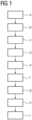
- FIG 1 shows schematically method steps a) to i) of a method according to an embodiment of the present invention, which serves to create a redundant automation system 1 for an automation system 2 to be controlled.
- a first step a information about the topology of a computer network 3 is provided.
- the computer network 3 is the Internet.
- the computer network 3 can also be a comparable computer network, such as a company intranet that connects a large number of company locations with one another via communication technology.
- the information provided in step a) is at least information about the structure or substructure of the computer network 3, which is formed by communication nodes 4 and communication paths 5 connecting them.
- the communication paths 5 can be wired and/or radio-based transmission routes.
- the information was obtained here based on static information, such as maps of the currently existing deep-sea cables and radio-based transmission routes. Information was also obtained by determining the network topology using network management protocols.
- step a additional information about the computer network 3 can be provided in step a), such as information about transmission speeds of individual communication paths 5, information collected from failure statistics about the probability of failure of communication nodes 4 and/or communication paths 5, etc.
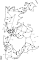
- FIG 2 shows an example of a network topology of the computer network 3 consisting of communication nodes 4 and communication paths 5, wherein a large number of communication nodes 4 and communication paths 5 are omitted for the sake of better clarity.
- step b information about the FIG 2
- the data centers 6 present in the network topology or connected to it are provided, including information about their locations. This is shown schematically in FIG 3 shown.
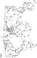
- step c If an automation system 1 is to be created for an automation system 2, the location of the automation system 2 within the network topology is identified in step c), see FIG 4 .
- step d at least one pair of data centers 6 is then identified which can be connected to the automation system 2 via communication paths 5 within the network topology and which have no overlaps and/or no common communication nodes.
- a total of 22 such pairs can be formed.
- Each of these pairs comprises an African data center 6 and a data center 6 located outside of Africa.
- step e) a pair of data centers 6 identified in step d) is then selected, including the associated communication paths 5. If, as is the case here, several pairs of data centers 6 were identified in step d), the selection in step e) can be made based on further criteria, such as the aforementioned transmission speeds of the individual communication paths 5, the probability of failure of communication nodes 4 and/or communication paths 5, etc.
- step b) additional information about the power supply and/or the current utilization and/or the computing power of the data centers 6 is also provided, which can be used in step e) to select an optimal pair. For example, in step e), it can be checked which pairs of data centers 6 have independent power supplies, with only pairs of data centers 6 with independent power supplies being shortlisted.
- the current utilization of the data centers 6 can be checked, with preference being given to pairs with data centers 6 with low utilization.
- a comparatively high computing power of both data centers 6 of a pair can also be decisive for the selection.
- Weighting factors can be assigned to the individual additional criteria in order to give them greater or lesser weight in the selection to be made in step e). to be given less weight.
- FIG 5 shows the final selection made in this example.
- control applications 7 set up to control the automation system 2 are then provided.
- the control applications 7 are set up in such a way that one of the control applications 7 works as a master and the other control application 7 works as a reserve, whereby in the event that the control application 7 working as a master fails, the control application 7 working as a reserve takes over its function as master.
- step g the control applications 7 are stored in the data centers 6 selected in step e).
- control applications 7 are then coupled in step h) via a synchronization path 8, which is preferably selected such that the synchronization path 8 and the two communication paths 5 connecting the control applications 7 to the automation system 2 have no overlaps and/or a minimal number of common communication nodes 4. If this is not possible, the communication paths 5 and the synchronization path 8 are selected such that they have as few overlaps and/or common nodes 4 as possible.
- step i) the control applications 7 are connected to the automation system 2 via the communication paths 5 selected in step e) and the data centers 6 via the selected synchronization path 8.
- the result is the FIG 6 shown arrangement or the one in FIG 7 automation system shown.
- a computer program comprising program code means which, when the program is executed on at least one computer, cause the at least one computer to carry out the steps of the method described above Only the identification of the plant location in step c) must be carried out by a user input.
- the automation system 1 is characterized by a very high level of availability despite the fact that its control applications 7 form part of a cloud computing structure. This availability can be further optimized by the type of synchronization mechanism with which the control applications 7 are synchronized and by the way in which the output data is handled in the redundant automation system 1.
- This context particular reference is made to the method described in the publication EP 2 657 797 B1 disclosed method for operating a redundant automation system 1, which can also be transferred to the redundant automation system 1 according to the invention.
Landscapes
- Engineering & Computer Science (AREA)
- Theoretical Computer Science (AREA)
- Physics & Mathematics (AREA)
- General Physics & Mathematics (AREA)
- General Engineering & Computer Science (AREA)
- Quality & Reliability (AREA)
- Automation & Control Theory (AREA)
- Computer Networks & Wireless Communication (AREA)
- Signal Processing (AREA)
- Manufacturing & Machinery (AREA)
- Computer Hardware Design (AREA)
- Hardware Redundancy (AREA)
Claims (3)
- Procédé de création d'un système (1) d'automatisation redondant, dans lequel le procédé a les stades :a) on se procure des informations sur une topologie de réseau d'un réseau informatique y compris des informations sur la structure ou la structure partielle du réseau informatique, qui est formée par des points (4) nodaux de communication et par des chemins (5) de communication reliant ceux-ci entre eux ;b) on se procure des informations sur des centres (6) de calcul présents au sein de la topologie du réseau y compris des informations sur leurs remplacements ;c) on identifie l'emplacement d'une installation (2) d'automatisation à commander au sein de la topologie du réseau ;d) on identifie au moins une paire de centres (6) de calcul, qui peuvent, au sein de la topologie du réseau, être reliés à l'installation d'automatisation sur des chemins de communication complètement indépendants les uns des autres de la topologie connue du réseau ;e) on sélectionne une paire identifiée au stade d) de centres (6) de calcul y compris les chemins (5) de communication leur appartenant ;f) on se procure deux applications (7) de commande agencées pour la commande de l'installation (2) d'automatisation, dans lequel les applications (7) de commande sont agencées, de manière à ce que l'une des applications (7) de commande opère en maître et de manière à ce que l'autre application (7) de commande opère en réserve et en ce que, dans le cas où l'application (7) de commande opérant en maître est défaillante, l'application (7) de commande opérant en réserve en prend en charge la fonction en tant que maître ;g) on met les applications (7) de commande en mémoire dans les centres (6) de calcul sélectionnés au stade e) ;h) on relie les applications (7) de commande par un chemin (8) de synchronisation ; eti) on relie les applications (7) de commande à l'installation (2) d'automatisation par les chemins (5) de communication sélectionnés dans le stade e), dans lequel on choisit un chemin (8) de synchronisation, de manière à ce que le chemin (8) de synchronisation et les deux chemins (5) de communication reliant les applications (7) de commande à l'installation (2) de communication n'aient pas de point (4) nodal de communication commun, caractérisé en ce que dans le stade b) on se procure des informations supplémentaires sur l'alimentation en courant et/ou sur la charge en cours et/ou sur la puissance de calcul des centres (6) de calcul et en ce que la sélection dans le stade e) s'effectue en tenant compte de l'une au moins de ces informations supplémentaires.
- Programme informatique comprenant des moyens de code de programme, qui, lors de la réalisation du programme sur au moins un ordinateur, font que le au moins ordinateur exécute les stades du procédé suivant la revendication 1.
- Support déchiffrable par ordinateur, qui comprend des instructions qui, lorsqu'elles sont exécutées sur au moins un ordinateur, font que le au moins ordinateur exécute les stades du procédé suivant la revendication 1.
Priority Applications (3)
| Application Number | Priority Date | Filing Date | Title |
|---|---|---|---|
| EP19201463.7A EP3800517B1 (fr) | 2019-10-04 | 2019-10-04 | Procédé de création d'un système d'automatisation redondant, programme informatique et support lisible par ordinateur |
| CN202011068904.XA CN112612201B (zh) | 2019-10-04 | 2020-09-30 | 自动化系统、创建自动化系统的方法和计算机可读介质 |
| US17/061,707 US11550270B2 (en) | 2019-10-04 | 2020-10-02 | Redundant automation system, method for creating the automation system, computer program and computer readable medium |
Applications Claiming Priority (1)
| Application Number | Priority Date | Filing Date | Title |
|---|---|---|---|
| EP19201463.7A EP3800517B1 (fr) | 2019-10-04 | 2019-10-04 | Procédé de création d'un système d'automatisation redondant, programme informatique et support lisible par ordinateur |
Publications (3)
| Publication Number | Publication Date |
|---|---|
| EP3800517A1 EP3800517A1 (fr) | 2021-04-07 |
| EP3800517B1 true EP3800517B1 (fr) | 2024-08-14 |
| EP3800517C0 EP3800517C0 (fr) | 2024-08-14 |
Family
ID=68165473
Family Applications (1)
| Application Number | Title | Priority Date | Filing Date |
|---|---|---|---|
| EP19201463.7A Active EP3800517B1 (fr) | 2019-10-04 | 2019-10-04 | Procédé de création d'un système d'automatisation redondant, programme informatique et support lisible par ordinateur |
Country Status (3)
| Country | Link |
|---|---|
| US (1) | US11550270B2 (fr) |
| EP (1) | EP3800517B1 (fr) |
| CN (1) | CN112612201B (fr) |
Families Citing this family (2)
| Publication number | Priority date | Publication date | Assignee | Title |
|---|---|---|---|---|
| EP4068014B1 (fr) * | 2021-03-30 | 2023-11-08 | Siemens Aktiengesellschaft | Solution d'automatisation en nuage hautement disponible à temps de transmission optimisés |
| US12500951B1 (en) * | 2024-05-29 | 2025-12-16 | Bank Of America Corporation | System and method for automated synchronization of data |
Family Cites Families (10)
| Publication number | Priority date | Publication date | Assignee | Title |
|---|---|---|---|---|
| EP2418580B1 (fr) * | 2010-08-10 | 2012-10-10 | Siemens Aktiengesellschaft | Procédé destiné au fonctionnement d'un réseau et réseau |
| CN102111299A (zh) * | 2011-03-07 | 2011-06-29 | 中控科技集团有限公司 | 冗余网络系统及其冗余实现方法 |
| EP2657797B1 (fr) * | 2012-04-27 | 2017-01-18 | Siemens Aktiengesellschaft | Procédé de fonctionnement d'un système d'automatisation redondant |
| JP5748363B2 (ja) * | 2013-02-01 | 2015-07-15 | 日本電信電話株式会社 | 通信経路設計装置、通信経路設計方法及び通信経路設計プログラム |
| DE102013106954A1 (de) * | 2013-07-02 | 2015-01-08 | Phoenix Contact Gmbh & Co. Kg | Verfahren zur Fehlerüberwachung, Steuer- und Datenübertragungsanlage und Steuereinrichtung |
| US11513477B2 (en) * | 2015-03-16 | 2022-11-29 | Rockwell Automation Technologies, Inc. | Cloud-based industrial controller |
| US10003522B2 (en) * | 2015-08-27 | 2018-06-19 | Facebook, Inc. | Routing with flow over shared risk link groups |
| KR20190007469A (ko) * | 2016-05-12 | 2019-01-22 | 달리 시스템즈 씨오. 엘티디. | 공공 안전 분산형 안테나 시스템에서의 리던던시 |
| US20190199626A1 (en) * | 2017-12-26 | 2019-06-27 | Cisco Technology, Inc. | Routing traffic across isolation networks |
| EP3547618B1 (fr) * | 2018-03-29 | 2023-03-01 | Siemens Aktiengesellschaft | Procédé d'établissement d'une connexion de communication redondante et unité de commande sécurisée |
-
2019
- 2019-10-04 EP EP19201463.7A patent/EP3800517B1/fr active Active
-
2020
- 2020-09-30 CN CN202011068904.XA patent/CN112612201B/zh active Active
- 2020-10-02 US US17/061,707 patent/US11550270B2/en active Active
Non-Patent Citations (2)
| Title |
|---|
| ANONYMOUS: "IP address - Wikipedia", WIKIPEDIA, 7 October 2019 (2019-10-07), pages 1 - 11, XP093003969, Retrieved from the Internet <URL:https://en.wikipedia.org/w/index.php?title=IP_address&oldid=920139052> [retrieved on 20221201] * |
| ANONYMOUS: "IP routing - Wikipedia", WIKIPEDIA, 7 October 2019 (2019-10-07), pages 1 - 3, XP093003854, Retrieved from the Internet <URL:https://en.wikipedia.org/w/index.php?title=IP_routing&oldid=920081455> [retrieved on 20221201] * |
Also Published As
| Publication number | Publication date |
|---|---|
| CN112612201A (zh) | 2021-04-06 |
| CN112612201B (zh) | 2024-06-21 |
| EP3800517A1 (fr) | 2021-04-07 |
| US20210103254A1 (en) | 2021-04-08 |
| EP3800517C0 (fr) | 2024-08-14 |
| US11550270B2 (en) | 2023-01-10 |
Similar Documents
| Publication | Publication Date | Title |
|---|---|---|
| DE2908316C2 (de) | Modular aufgebaute Multiprozessor-Datenverarbeitungsanlage | |
| DE69801418T2 (de) | Datenaufteilung und -dupliziering in einem verteilten datenverarbeitungssystem | |
| DE60318468T2 (de) | Verfahren zur lösung von entscheidungslosigkeiten in einem cluster-rechnersystem | |
| EP2667269B1 (fr) | Procédé de fonctionnement d'un système d'automatisation redondant | |
| DE3751230T2 (de) | Selbstgleichsetzung in redundanten Kanälen. | |
| DE102012000158B4 (de) | Adaptives mehrfach redundantes ringförmiges Netzwerk und Verfahren zum Wählen einer Umleitung | |
| DE102012003242A1 (de) | Verfahren zum ausfallsicheren Betreiben eines Prozesssteuersystems mit redundanten Steuereinrichtungen | |
| EP3017570B1 (fr) | Dispositif de controle, noeud de reseau et procede pour l'echange des donnees sur un reseau | |
| DE4305522A1 (de) | Einrichtung zur automatischen Erzeugung einer Wissensbasis für ein Diagnose-Expertensystem | |
| DE102016219854A1 (de) | Computersystem und Verfahren zum dynamischen Anpassen eines software-definierten Netzwerks | |
| DE19780639C2 (de) | Arbeitsübernahmesystem | |
| WO2002065289A1 (fr) | Mise en marche automatique d'un systeme a configuration en grappe apres une erreur reparable | |
| WO2005073852A1 (fr) | Procede permettant de faire fonctionner un ensemble de plusieurs ordinateurs en cas de defaillance d'un ordinateur | |
| EP2732347A1 (fr) | Procédé et système de répartition dynamique de fonctions de programme dans des systèmes de commande répartis | |
| EP3800517A1 (fr) | Système d'automatisation redondant, procédé de création d'un tel système d'automatisation, programme informatique et support lisible par ordinateur | |
| DE102020200453A1 (de) | Multi-Cloud-Industriecontroller | |
| EP2418580B1 (fr) | Procédé destiné au fonctionnement d'un réseau et réseau | |
| EP4335127B1 (fr) | Procédé mis en oeuvre par ordinateur destiné au fonctionnement d'un terminal à haute disponibilité dans un réseau | |
| EP1820307B1 (fr) | Procede permettant de controler la disponibilite de composantes dans un systeme de communication redondant | |
| EP1743224A1 (fr) | Dispositif et procede pour faire fonctionner une installation technique | |
| EP2021922B1 (fr) | Procédé et dispositif de gestion de tolérance aux pannes d'un composant logiciel | |
| WO2016079091A1 (fr) | Procédé de fonctionnement d'un premier et d'au moins un deuxième appareil de terrain | |
| DE10049621A1 (de) | Verfahren zum Betreiben eines Datenverarbeitungssystem | |
| DE10025283B4 (de) | Vorrichtung zur dynamischen Verbindung von mindestens zwei Datenringzellen | |
| LU101163B1 (de) | Verfahren und Vorrichtungen für eine Lastzuweisung und Überwachung für eine zuzuweisende versorgungssicherheitskritische Ressource in einem Netzwerk |
Legal Events
| Date | Code | Title | Description |
|---|---|---|---|
| PUAI | Public reference made under article 153(3) epc to a published international application that has entered the european phase |
Free format text: ORIGINAL CODE: 0009012 |
|
| STAA | Information on the status of an ep patent application or granted ep patent |
Free format text: STATUS: THE APPLICATION HAS BEEN PUBLISHED |
|
| AK | Designated contracting states |
Kind code of ref document: A1 Designated state(s): AL AT BE BG CH CY CZ DE DK EE ES FI FR GB GR HR HU IE IS IT LI LT LU LV MC MK MT NL NO PL PT RO RS SE SI SK SM TR |
|
| AX | Request for extension of the european patent |
Extension state: BA ME |
|
| STAA | Information on the status of an ep patent application or granted ep patent |
Free format text: STATUS: REQUEST FOR EXAMINATION WAS MADE |
|
| 17P | Request for examination filed |
Effective date: 20211006 |
|
| RBV | Designated contracting states (corrected) |
Designated state(s): AL AT BE BG CH CY CZ DE DK EE ES FI FR GB GR HR HU IE IS IT LI LT LU LV MC MK MT NL NO PL PT RO RS SE SI SK SM TR |
|
| STAA | Information on the status of an ep patent application or granted ep patent |
Free format text: STATUS: EXAMINATION IS IN PROGRESS |
|
| 17Q | First examination report despatched |
Effective date: 20221207 |
|
| GRAP | Despatch of communication of intention to grant a patent |
Free format text: ORIGINAL CODE: EPIDOSNIGR1 |
|
| STAA | Information on the status of an ep patent application or granted ep patent |
Free format text: STATUS: GRANT OF PATENT IS INTENDED |
|
| RIC1 | Information provided on ipc code assigned before grant |
Ipc: G06F 11/20 20060101ALI20240321BHEP Ipc: G05B 19/418 20060101ALI20240321BHEP Ipc: G05B 9/03 20060101AFI20240321BHEP |
|
| INTG | Intention to grant announced |
Effective date: 20240419 |
|
| GRAS | Grant fee paid |
Free format text: ORIGINAL CODE: EPIDOSNIGR3 |
|
| GRAA | (expected) grant |
Free format text: ORIGINAL CODE: 0009210 |
|
| STAA | Information on the status of an ep patent application or granted ep patent |
Free format text: STATUS: THE PATENT HAS BEEN GRANTED |
|
| AK | Designated contracting states |
Kind code of ref document: B1 Designated state(s): AL AT BE BG CH CY CZ DE DK EE ES FI FR GB GR HR HU IE IS IT LI LT LU LV MC MK MT NL NO PL PT RO RS SE SI SK SM TR |
|
| REG | Reference to a national code |
Ref country code: GB Ref legal event code: FG4D Free format text: NOT ENGLISH |
|
| REG | Reference to a national code |
Ref country code: CH Ref legal event code: EP |
|
| REG | Reference to a national code |
Ref country code: DE Ref legal event code: R096 Ref document number: 502019011876 Country of ref document: DE |
|
| REG | Reference to a national code |
Ref country code: IE Ref legal event code: FG4D Free format text: LANGUAGE OF EP DOCUMENT: GERMAN |
|
| U01 | Request for unitary effect filed |
Effective date: 20240814 |
|
| U07 | Unitary effect registered |
Designated state(s): AT BE BG DE DK EE FI FR IT LT LU LV MT NL PT RO SE SI Effective date: 20240902 |
|
| U20 | Renewal fee for the european patent with unitary effect paid |
Year of fee payment: 6 Effective date: 20241018 |
|
| PG25 | Lapsed in a contracting state [announced via postgrant information from national office to epo] |
Ref country code: NO Free format text: LAPSE BECAUSE OF FAILURE TO SUBMIT A TRANSLATION OF THE DESCRIPTION OR TO PAY THE FEE WITHIN THE PRESCRIBED TIME-LIMIT Effective date: 20241114 |
|
| PG25 | Lapsed in a contracting state [announced via postgrant information from national office to epo] |
Ref country code: GR Free format text: LAPSE BECAUSE OF FAILURE TO SUBMIT A TRANSLATION OF THE DESCRIPTION OR TO PAY THE FEE WITHIN THE PRESCRIBED TIME-LIMIT Effective date: 20241115 Ref country code: PL Free format text: LAPSE BECAUSE OF FAILURE TO SUBMIT A TRANSLATION OF THE DESCRIPTION OR TO PAY THE FEE WITHIN THE PRESCRIBED TIME-LIMIT Effective date: 20240814 |
|
| PG25 | Lapsed in a contracting state [announced via postgrant information from national office to epo] |
Ref country code: IS Free format text: LAPSE BECAUSE OF FAILURE TO SUBMIT A TRANSLATION OF THE DESCRIPTION OR TO PAY THE FEE WITHIN THE PRESCRIBED TIME-LIMIT Effective date: 20241214 |
|
| PG25 | Lapsed in a contracting state [announced via postgrant information from national office to epo] |
Ref country code: HR Free format text: LAPSE BECAUSE OF FAILURE TO SUBMIT A TRANSLATION OF THE DESCRIPTION OR TO PAY THE FEE WITHIN THE PRESCRIBED TIME-LIMIT Effective date: 20240814 |
|
| PG25 | Lapsed in a contracting state [announced via postgrant information from national office to epo] |
Ref country code: RS Free format text: LAPSE BECAUSE OF FAILURE TO SUBMIT A TRANSLATION OF THE DESCRIPTION OR TO PAY THE FEE WITHIN THE PRESCRIBED TIME-LIMIT Effective date: 20241114 Ref country code: ES Free format text: LAPSE BECAUSE OF FAILURE TO SUBMIT A TRANSLATION OF THE DESCRIPTION OR TO PAY THE FEE WITHIN THE PRESCRIBED TIME-LIMIT Effective date: 20240814 |
|
| PG25 | Lapsed in a contracting state [announced via postgrant information from national office to epo] |
Ref country code: RS Free format text: LAPSE BECAUSE OF FAILURE TO SUBMIT A TRANSLATION OF THE DESCRIPTION OR TO PAY THE FEE WITHIN THE PRESCRIBED TIME-LIMIT Effective date: 20241114 Ref country code: PL Free format text: LAPSE BECAUSE OF FAILURE TO SUBMIT A TRANSLATION OF THE DESCRIPTION OR TO PAY THE FEE WITHIN THE PRESCRIBED TIME-LIMIT Effective date: 20240814 Ref country code: NO Free format text: LAPSE BECAUSE OF FAILURE TO SUBMIT A TRANSLATION OF THE DESCRIPTION OR TO PAY THE FEE WITHIN THE PRESCRIBED TIME-LIMIT Effective date: 20241114 Ref country code: IS Free format text: LAPSE BECAUSE OF FAILURE TO SUBMIT A TRANSLATION OF THE DESCRIPTION OR TO PAY THE FEE WITHIN THE PRESCRIBED TIME-LIMIT Effective date: 20241214 Ref country code: HR Free format text: LAPSE BECAUSE OF FAILURE TO SUBMIT A TRANSLATION OF THE DESCRIPTION OR TO PAY THE FEE WITHIN THE PRESCRIBED TIME-LIMIT Effective date: 20240814 Ref country code: GR Free format text: LAPSE BECAUSE OF FAILURE TO SUBMIT A TRANSLATION OF THE DESCRIPTION OR TO PAY THE FEE WITHIN THE PRESCRIBED TIME-LIMIT Effective date: 20241115 Ref country code: ES Free format text: LAPSE BECAUSE OF FAILURE TO SUBMIT A TRANSLATION OF THE DESCRIPTION OR TO PAY THE FEE WITHIN THE PRESCRIBED TIME-LIMIT Effective date: 20240814 |
|
| PG25 | Lapsed in a contracting state [announced via postgrant information from national office to epo] |
Ref country code: SM Free format text: LAPSE BECAUSE OF FAILURE TO SUBMIT A TRANSLATION OF THE DESCRIPTION OR TO PAY THE FEE WITHIN THE PRESCRIBED TIME-LIMIT Effective date: 20240814 |
|
| PG25 | Lapsed in a contracting state [announced via postgrant information from national office to epo] |
Ref country code: CZ Free format text: LAPSE BECAUSE OF FAILURE TO SUBMIT A TRANSLATION OF THE DESCRIPTION OR TO PAY THE FEE WITHIN THE PRESCRIBED TIME-LIMIT Effective date: 20240814 |
|
| PG25 | Lapsed in a contracting state [announced via postgrant information from national office to epo] |
Ref country code: SK Free format text: LAPSE BECAUSE OF FAILURE TO SUBMIT A TRANSLATION OF THE DESCRIPTION OR TO PAY THE FEE WITHIN THE PRESCRIBED TIME-LIMIT Effective date: 20240814 |
|
| REG | Reference to a national code |
Ref country code: CH Ref legal event code: PL |
|
| PLBE | No opposition filed within time limit |
Free format text: ORIGINAL CODE: 0009261 |
|
| STAA | Information on the status of an ep patent application or granted ep patent |
Free format text: STATUS: NO OPPOSITION FILED WITHIN TIME LIMIT |
|
| PG25 | Lapsed in a contracting state [announced via postgrant information from national office to epo] |
Ref country code: MC Free format text: LAPSE BECAUSE OF FAILURE TO SUBMIT A TRANSLATION OF THE DESCRIPTION OR TO PAY THE FEE WITHIN THE PRESCRIBED TIME-LIMIT Effective date: 20240814 |
|
| 26N | No opposition filed |
Effective date: 20250515 |
|
| GBPC | Gb: european patent ceased through non-payment of renewal fee |
Effective date: 20241114 |
|
| PG25 | Lapsed in a contracting state [announced via postgrant information from national office to epo] |
Ref country code: CH Free format text: LAPSE BECAUSE OF NON-PAYMENT OF DUE FEES Effective date: 20241031 |
|
| PG25 | Lapsed in a contracting state [announced via postgrant information from national office to epo] |
Ref country code: GB Free format text: LAPSE BECAUSE OF NON-PAYMENT OF DUE FEES Effective date: 20241114 |
|
| PG25 | Lapsed in a contracting state [announced via postgrant information from national office to epo] |
Ref country code: IE Free format text: LAPSE BECAUSE OF NON-PAYMENT OF DUE FEES Effective date: 20241004 |
|
| U20 | Renewal fee for the european patent with unitary effect paid |
Year of fee payment: 7 Effective date: 20251020 |
|
| PG25 | Lapsed in a contracting state [announced via postgrant information from national office to epo] |
Ref country code: CY Free format text: LAPSE BECAUSE OF FAILURE TO SUBMIT A TRANSLATION OF THE DESCRIPTION OR TO PAY THE FEE WITHIN THE PRESCRIBED TIME-LIMIT; INVALID AB INITIO Effective date: 20191004 |
|
| PG25 | Lapsed in a contracting state [announced via postgrant information from national office to epo] |
Ref country code: HU Free format text: LAPSE BECAUSE OF FAILURE TO SUBMIT A TRANSLATION OF THE DESCRIPTION OR TO PAY THE FEE WITHIN THE PRESCRIBED TIME-LIMIT; INVALID AB INITIO Effective date: 20191004 |
|
| PG25 | Lapsed in a contracting state [announced via postgrant information from national office to epo] |
Ref country code: TR Free format text: LAPSE BECAUSE OF FAILURE TO SUBMIT A TRANSLATION OF THE DESCRIPTION OR TO PAY THE FEE WITHIN THE PRESCRIBED TIME-LIMIT Effective date: 20240814 |