EP3802040B1 - Système de support de moule - Google Patents
Système de support de moule Download PDFInfo
- Publication number
- EP3802040B1 EP3802040B1 EP19733964.1A EP19733964A EP3802040B1 EP 3802040 B1 EP3802040 B1 EP 3802040B1 EP 19733964 A EP19733964 A EP 19733964A EP 3802040 B1 EP3802040 B1 EP 3802040B1
- Authority
- EP
- European Patent Office
- Prior art keywords
- mold
- locking
- mold support
- clamping plate
- support system
- Prior art date
- Legal status (The legal status is an assumption and is not a legal conclusion. Google has not performed a legal analysis and makes no representation as to the accuracy of the status listed.)
- Active
Links
Images


Classifications
-
- B—PERFORMING OPERATIONS; TRANSPORTING
- B29—WORKING OF PLASTICS; WORKING OF SUBSTANCES IN A PLASTIC STATE IN GENERAL
- B29C—SHAPING OR JOINING OF PLASTICS; SHAPING OF MATERIAL IN A PLASTIC STATE, NOT OTHERWISE PROVIDED FOR; AFTER-TREATMENT OF THE SHAPED PRODUCTS, e.g. REPAIRING
- B29C33/00—Moulds or cores; Details thereof or accessories therefor
- B29C33/20—Opening, closing or clamping
-
- B—PERFORMING OPERATIONS; TRANSPORTING
- B29—WORKING OF PLASTICS; WORKING OF SUBSTANCES IN A PLASTIC STATE IN GENERAL
- B29C—SHAPING OR JOINING OF PLASTICS; SHAPING OF MATERIAL IN A PLASTIC STATE, NOT OTHERWISE PROVIDED FOR; AFTER-TREATMENT OF THE SHAPED PRODUCTS, e.g. REPAIRING
- B29C45/00—Injection moulding, i.e. forcing the required volume of moulding material through a nozzle into a closed mould; Apparatus therefor
- B29C45/17—Component parts, details or accessories; Auxiliary operations
- B29C45/64—Mould opening, closing or clamping devices
- B29C45/66—Mould opening, closing or clamping devices mechanical
Definitions
- the invention relates to a mold carrier system according to the preamble of patent claim 1.
- a generic mold carrier system is off AT 513 131 B1 is known, in which a movable mold platen arranged on a holding device can be positioned by means of a locking drive in one of several relatively coarse latching positions arranged vertically one above the other.
- Another mold carrier system is known from the applicant's in-house company brochure High Speed Systems.
- a mold carrier upper part is locked to a frame by means of a locking means, which is formed from two locking bushes on a frame support and at least one locking bolt on the mold carrier upper part engaging in these locking bushes.
- a locking position of the upper part of the mold carrier with the frame is only possible for a maximum of two different mold heights.
- WO 93/16828 A1 discloses a locking device for a closing device of an injection molding machine, in which a push rod is provided with grooves and projections, into which corresponding projections and grooves of a nut-like locking ring engage.
- a clamping unit for molds is known in which long-stroke cylinders are provided for lowering and raising the upper mold half and additional short-stroke cylinders are provided to reduce the working time.
- a use of a compressed air cushion on a mold is out DE 699 07 227 T2 known per se, but is used there only for the purpose of compensating for material shrinkage and not for fine positioning of tools.
- the object of the invention is to create a mold carrier system that enables fine adjustment to different tool heights in a large number of positions.
- Mold carrier systems for encapsulating glass covers or panes with foam are used, for example, in the manufacture of sunroofs for vehicles.
- the mold carrier system comprises a portal-like frame with a mold carrier upper part that can be moved relative to the frame and has a first mold clamping plate and a mold carrier lower part with a second mold clamping plate. Furthermore, first locking means are provided on the frame and second locking means are provided on the upper part of the mold carrier. These two locking means enable the upper part of the mold carrier to be locked in a variable locking position relative to the frame.
- the first and the second locking means are formed by a large number of locking elements which are spaced evenly apart and which can be brought into engagement in different locking positions.
- the first locking element is designed as a plate and the second locking element is designed as a bolt.
- the locking elements of the first and second locking means are formed by projections and depressions. In the locking position, the projections of the bolt then engage in the depressions of the plate and the projections of the plate engage in the depressions of the bolt. This creates a kind of interlocking of the two locking means.
- the first locking element can be designed as a bolt and the second locking element can be designed as a plate.
- variable air gap is additionally provided according to the invention between the mold clamping plate and the upper or lower part of the mold carrier.
- This variable air gap enables a so-called floating mounting of the mold clamping plate.
- Inflatable or deaerable compressed air cushions with variable volumes between the mold clamping plate and the upper or lower part of the mold carrier allow stepless fine positioning of the mold clamping plates with different mold height settings.
- the first and second locking means are engageable by means of a locking device.
- the locking element comprises at least one horizontally movable locking element, which can be moved by a drive.
- the drive can be formed as an electric motor, hydraulic cylinder or pneumatic cylinder.
- a sensor for measuring a distance between the first mold mounting plate and the frame.
- the sensor determines a target value for the locking position of the first mold clamping plate by laser measurement.
- This target value of the locking position is determined by a manual process in a creeper.
- the first mold clamping plate is moved very slowly against the second mold clamping plate until the desired locking position is reached.
- the desired value determined in this way can be transferred to a memory of a programmable logic controller (PLC) for subsequent, automated traversing operations of the first mold mounting plate.
- PLC programmable logic controller
- the lower part of the mold carrier with the second mold clamping plate can also be movably mounted on the frame. Both or just one of the platens can be moved.
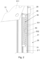
- the mold carrier system 10 is shown with a portal-like frame 20 .
- the frame 20 is formed by a first portal support 21, a second portal support 22, a yoke 23 arranged at the top horizontally connecting the two portal supports 21 and 22, and a lower traverse 28 horizontally connecting the two portal supports 21 and 22.
- a mold carrier upper part 30 and a mold carrier lower part 40 are arranged pivotably about the axes A30 and A40.
- the swiveling storage is used for more convenient insertion and removal of the components and for easier cleaning of the molds.
- the upper mold carrier part 30 has a first mold clamping plate 31 with a clamping surface 311 and the lower mold carrier part 40 has a second mold clamping plate 41 with a clamping surface 411 .
- the mounting surface 311 is for mounting an upper mold and the mounting surface 411 is for mounting a lower mold, both of which are not shown to simplify the drawing.
- a running rail 26 On the two portal supports 21 and 22 there is a running rail 26 with a guide carriage 25 sliding therein for the vertical movement of the upper part 30 of the mold carrier.
- the guide carriages 25 are driven by a drive 24 which is arranged, for example, on an outside 212 of the portal support 21 .
- a first locking means 50 is arranged, which is designed as a plate 51 and a plurality of evenly spaced Locking elements 53 has.
- the second locking element 60 is arranged on an outer side 312 of the mold carrier upper part 30 (shown in detail in FIGS Figures 3 to 5 ).
- a sensor 27 for measuring a distance between the first platen 31 and the frame 20 is provided on the yoke 23 of the frame 20 to determine the desired locking position.
- the sensor 27 uses a laser to determine a target value for the locking position of the first mold clamping plate 31.
- This target value of the locking position is determined by a manual process in a crawling or crawling speed. After the introduction of a new mold, the first mold clamping plate 31 is moved very slowly against the second mold clamping plate 41 until the desired locking position is reached. The target value determined in this way as the distance A between the stationary yoke 23 and the movable first mold clamping plate 30 can be converted into an in 1 indicated memory 82 of a programmable logic controller (PLC) 80 are transmitted.
- PLC programmable logic controller
- the locking elements 53 are designed as projections 531 and depressions 532 .
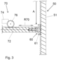
- the figure 3 shows a schematic sectional view of the locking elements 50 and 60, as well as a locking device 70 connected to the bolt 61 of the second locking means 60.
- the locking device 70 comprises a horizontally movable locking element 72, a drive 74 for a gear wheel 76, which moves the locking element 72 in one direction of movement makes the R70 moveable.
- the drive can be designed, for example, as an electric motor, as a hydraulic cylinder or as a pneumatic cylinder.
- Such a synchronously horizontally movable bolt 61 is also on the opposite Side with a arranged on the inside of the second portal support 22, not shown, plate 51 engageable.
- the locking element 53 is brought into engagement with a locking element 63 by the movement of the horizontal locking element 72 .
- Projections 631 and depressions 632 are also formed on the locking element 63 .
- the projections 631 of the latch 61 engage in the indentations 532 of the plate 51 and the projections 531 of the plate 51 in the indentations 632 of the latch 61 (see FIG Figures 4 and 5 ).
- a variable air gap L is provided in the vertical direction between the projections 531 and 631 and the depressions 532 and 632, respectively.
- the air gap L enables a so-called floating mounting of the first mold clamping plate 31.
- the air gap L is about 2 mm according to the invention .
- the second mold clamping plate 41 can also be mounted in a floating manner. Finer teeth with a tooth spacing of 3 mm between the projections 531 and 631 can also be realized.
- the first mold mounting plate 31 is moved to a specific height, so that the locking elements 63 can engage in the locking elements 53 .
- the floating mounting through the air gap L is necessary in order to enable the desired, almost infinitely variable adjustment of the tool height.
- the desired gap S is determined by at least one in 6 illustrated inflatable or ventable compressed air cushion 32 is set, which is effective between the mold mounting plate 31 and the upper mold carrier upper part 30 carrying it and/or between the mold mounting plate 41 and the mold carrier lower part 40 carrying it.
- the setpoint for the required Filling level of the compressed air cushion 32 can also be transferred to a memory 82 of the programmable logic controller (PLC) 80 .
- PLC programmable logic controller
- FIGS. 4 and 5 show a schematic sectional view through the two locking means 50 and 60 in an unlocked and a locked position.
- the reference numbers correspond to those previously described Figures 1 to 3 .
Landscapes
- Engineering & Computer Science (AREA)
- Mechanical Engineering (AREA)
- Manufacturing & Machinery (AREA)
- Moulds For Moulding Plastics Or The Like (AREA)
Claims (11)
- Système de support de moule (10) comprenant un cadre en forme de portique (20), une partie supérieure de support de moule (30) mobile par rapport au cadre (20) avec une première plaque de serrage de moule (31), une partie inférieure de support de moule (40) avec une deuxième plaque de serrage de moule (41), des premiers moyens de verrouillage (50) prévus sur le cadre (20) et des deuxièmes moyens de verrouillage (50) prévus sur le cadre (20), des moyens de verrouillage (60) prévus sur la partie supérieure de support de moule (30) pour verrouiller la partie supérieure de support de moule (30) par rapport au cadre (20) dans une position de verrouillage, les premiers moyens de verrouillage (50) et/ou les seconds moyens de verrouillage (60) étant constitués d'une pluralité d'éléments de verrouillage (53 ; 63) configurés pour pouvoir être mis en prise dans différentes positions de verrouillage, caractérisé en ce qu'il est prévu au moins un coussin d'air comprimé (32) pour un positionnement fin continu de la première plaque de serrage de moule (31) et/ou de la deuxième plaque de serrage de moule (41) sur la partie supérieure de support de moule (30) et/ou sur la partie inférieure de support de moule (40).
- Système de support de moule (10) selon la revendication 1, caractérisé en ce que le premier moyen de verrouillage (50) et le deuxième moyen de verrouillage (60) sont réalisés sous forme de plaque (51) et/ou de loquet (61), sur lesquels les éléments de verrouillage (53 ; 63) sont réalisés sous forme de saillies (531 ; 631) et des creux (532 ; 632) sont formés ou disposés, les saillies (631) du loquet (61) s'engageant dans les creux (532) de la plaque (51) et les saillies (531) de la plaque (51) s'engageant dans les creux (632) du loquet (61) dans une position de verrouillage.
- Système de support de moule (10) selon la revendication 2, caractérisé en ce qu'il est prévu entre les saillies (531 ; 631) et les creux (532 ; 632) un entrefer variable (L) qui permet, sur la partie supérieure de support de moule (30), un montage flottant de la première plaque de serrage de moule (31) et/ou, sur la partie inférieure de support de moule (40), un montage flottant de la deuxième plaque de serrage de moule (41) pour un réglage en continu des hauteurs d'outil.
- Système de support de moule (10) selon l'une des revendications précédentes, caractérisé en ce que les moyens de verrouillage (53 ; 63) sont configurés de façon à pouvoir être mis en prise au moyen d'un dispositif de verrouillage (70).
- Système de support de moule (10) selon la revendication 4, caractérisé en ce que le dispositif de verrouillage (70) comprend au moins un élément de verrouillage (72) mobile horizontalement.
- Système de support de moule (10) selon la revendication 5, caractérisé en ce que l'élément de verrouillage (72) est déplaçable au moyen d'un entraînement (74).
- Système de support de moule (10) selon la revendication 6, caractérisé en ce que l'entraînement (74) est formé par un moteur électrique, un vérin hydraulique ou un vérin pneumatique.
- Système de support de moule (10) selon l'une des revendications précédentes, caractérisé en ce qu'un capteur (27) est prévu pour mesurer une distance (A) entre la première plaque de serrage de moule (31) et le cadre (20).
- Système de support de moule (10) selon la revendication 8, caractérisé en ce que le capteur (27) détermine au moyen d'un laser une valeur de consigne pour une position de verrouillage de la première plaque de serrage de moule (31).
- Système de support de moule (10) selon la revendication 9, caractérisé en ce que la valeur de consigne est déterminée par un déplacement manuel de la première plaque de serrage de moule (31) contre la deuxième plaque de serrage de moule (41) dans un mouvement de fluage et est transférée dans une mémoire d'une commande programmable (SPS) en tant que valeur de consigne pour des processus de déplacement automatisés subséquents de la première plaque de serrage de moule (31).
- Système de support de moule (10) selon l'une des revendications précédentes, caractérisé en ce que la partie inférieure de support de moule (40) avec la deuxième plaque de serrage de moule (41) est montée de manière mobile sur le cadre (20).
Applications Claiming Priority (3)
| Application Number | Priority Date | Filing Date | Title |
|---|---|---|---|
| DE102018113657 | 2018-06-08 | ||
| DE102018117586.8A DE102018117586A1 (de) | 2018-06-08 | 2018-07-20 | Formenträgersystem |
| PCT/EP2019/064903 WO2019234206A1 (fr) | 2018-06-08 | 2019-06-06 | Système de support de moule |
Publications (3)
| Publication Number | Publication Date |
|---|---|
| EP3802040A1 EP3802040A1 (fr) | 2021-04-14 |
| EP3802040C0 EP3802040C0 (fr) | 2023-06-07 |
| EP3802040B1 true EP3802040B1 (fr) | 2023-06-07 |
Family
ID=68651507
Family Applications (1)
| Application Number | Title | Priority Date | Filing Date |
|---|---|---|---|
| EP19733964.1A Active EP3802040B1 (fr) | 2018-06-08 | 2019-06-06 | Système de support de moule |
Country Status (3)
| Country | Link |
|---|---|
| EP (1) | EP3802040B1 (fr) |
| DE (1) | DE102018117586A1 (fr) |
| WO (1) | WO2019234206A1 (fr) |
Families Citing this family (2)
| Publication number | Priority date | Publication date | Assignee | Title |
|---|---|---|---|---|
| DE102020101061A1 (de) | 2020-01-17 | 2021-07-22 | Bbg Gmbh & Co. Kg | Formenträgersystem |
| CN116100729B (zh) * | 2023-04-14 | 2023-06-20 | 晋江全信机械有限公司 | 一种全自动eva二次成型圆盘机 |
Family Cites Families (6)
| Publication number | Priority date | Publication date | Assignee | Title |
|---|---|---|---|---|
| DE3538683A1 (de) * | 1985-10-31 | 1987-05-07 | Hennecke Gmbh Maschf | Schliesseinheit fuer formwerkzeuge, insbesondere solchen fuer die herstellung von polyurethan-formteilen |
| ATA30692A (de) * | 1992-02-20 | 1993-07-15 | Engel Gmbh Maschbau | Verriegelungsvorrichtung, insbesondere für eine schliessvorrichtung einer spritzgiessmaschine |
| DE4309496A1 (de) * | 1993-03-24 | 1994-09-29 | Spiess Kunststoff Recycling | Verfahren und Vorrichtung zum Befüllen von Gießformen mit plastifiziertem Kunststoff, insbesondere mit stark verunreinigtem Kunststoff-Recycling |
| DE19612018B4 (de) * | 1996-03-18 | 2005-09-29 | Dreier Technology Ag | Formmaschine |
| GB9819415D0 (en) * | 1998-09-07 | 1998-10-28 | Ici Plc | A mould and apparatus thereof |
| AT513131B1 (de) * | 2013-01-28 | 2014-02-15 | Engel Austria Gmbh | Schließeinheit für eine Spritzgießmaschine |
-
2018
- 2018-07-20 DE DE102018117586.8A patent/DE102018117586A1/de active Pending
-
2019
- 2019-06-06 EP EP19733964.1A patent/EP3802040B1/fr active Active
- 2019-06-06 WO PCT/EP2019/064903 patent/WO2019234206A1/fr not_active Ceased
Also Published As
| Publication number | Publication date |
|---|---|
| EP3802040A1 (fr) | 2021-04-14 |
| DE102018117586A1 (de) | 2019-12-12 |
| WO2019234206A1 (fr) | 2019-12-12 |
| EP3802040C0 (fr) | 2023-06-07 |
Similar Documents
| Publication | Publication Date | Title |
|---|---|---|
| EP0895848B1 (fr) | Dispositif de fabrication d'articles moulés par injection d'au moins deux matières plastiques fondues | |
| EP3697597B1 (fr) | Dispositif de levage pour un cylindre de construction dans une machine, machine pour produire des composants tridimensionnels avec un dispositif de levage et procédé de commande du dispositif de levage | |
| EP1882580B1 (fr) | Conteneur interchangeable | |
| EP1226916A1 (fr) | Dispositif et procédé pour la production d'objects en matière plastic | |
| DE2550824C2 (de) | Karussell-Formmaschine | |
| AT522911B1 (de) | Gusswerkzeug-Spannvorrichtung mit einer Halbmutter und Spritzgießvorrichtung | |
| AT403134B (de) | Formwechseleinrichtung für spritzgiessmaschinen | |
| DE3522377A1 (de) | Verfahren und vorrichtung zum herstellen von formteilen aus einem massiven oder mikrozellularen kunststoff, insbesondere polyurethan bildenden, fliessfaehigen reaktionsgemisch aus mindestens zwei fliessfaehigen reaktionskomponenten | |
| EP3802040B1 (fr) | Système de support de moule | |
| DE3312539C1 (de) | Vorrichtung zum Herstellen von kastenlosen Sandgießformen | |
| WO2020070210A1 (fr) | Unité de fermeture de moule destinée à une machine de moulage par injection ainsi que procédé de blocage d'un élément de transmission de force | |
| EP0761401A2 (fr) | Moule pour la fabrication de briques | |
| WO2013072459A2 (fr) | Dispositif de verrouillage de longerons d'une machine de traitement de matière plastique | |
| EP0317721A2 (fr) | Presse pour la fabrication d'articles sanitaires, en particulier de cuvettes de w.c., par moulage sous pression | |
| EP0583718B1 (fr) | Machine à mouler des matières plastiques par injection | |
| EP0896866B1 (fr) | Procédé et dispositif pour la fabrication d'éléments moulés | |
| EP0087575B1 (fr) | Machine à mouler pour la production de moules sans châssis | |
| DE3529775C2 (fr) | ||
| DE19922684C2 (de) | Blasformmaschine für das abfallarme Blasen | |
| EP0693351B1 (fr) | Dispositif pour la fabrication d'éléments en béton | |
| EP4003692B1 (fr) | Unité de fermeture pour une machine de moulage par soufflage | |
| EP1848577B1 (fr) | Machine de moulage par injection pour l'usinage de matieres plastiques | |
| DE10115653B4 (de) | Spannsystem zum Spannen und ggf. Zentrieren von Profilrahmen in Kombination mit einer Putzvorrichtung mit wenigstens zwei Bearbeitungseinheiten und zugehöriges Verfahren | |
| DE102011014783B4 (de) | Verriegelungsvorrichtung für Holme einer Kunststoffverarbeitungsmaschine | |
| DD298073A5 (de) | Werkzeugwechselvorrichtung fuer kunststofformmaschinen |
Legal Events
| Date | Code | Title | Description |
|---|---|---|---|
| STAA | Information on the status of an ep patent application or granted ep patent |
Free format text: STATUS: UNKNOWN |
|
| STAA | Information on the status of an ep patent application or granted ep patent |
Free format text: STATUS: THE INTERNATIONAL PUBLICATION HAS BEEN MADE |
|
| PUAI | Public reference made under article 153(3) epc to a published international application that has entered the european phase |
Free format text: ORIGINAL CODE: 0009012 |
|
| STAA | Information on the status of an ep patent application or granted ep patent |
Free format text: STATUS: REQUEST FOR EXAMINATION WAS MADE |
|
| 17P | Request for examination filed |
Effective date: 20201221 |
|
| AK | Designated contracting states |
Kind code of ref document: A1 Designated state(s): AL AT BE BG CH CY CZ DE DK EE ES FI FR GB GR HR HU IE IS IT LI LT LU LV MC MK MT NL NO PL PT RO RS SE SI SK SM TR |
|
| AX | Request for extension of the european patent |
Extension state: BA ME |
|
| DAV | Request for validation of the european patent (deleted) | ||
| DAX | Request for extension of the european patent (deleted) | ||
| GRAP | Despatch of communication of intention to grant a patent |
Free format text: ORIGINAL CODE: EPIDOSNIGR1 |
|
| STAA | Information on the status of an ep patent application or granted ep patent |
Free format text: STATUS: GRANT OF PATENT IS INTENDED |
|
| INTG | Intention to grant announced |
Effective date: 20230123 |
|
| GRAS | Grant fee paid |
Free format text: ORIGINAL CODE: EPIDOSNIGR3 |
|
| GRAA | (expected) grant |
Free format text: ORIGINAL CODE: 0009210 |
|
| STAA | Information on the status of an ep patent application or granted ep patent |
Free format text: STATUS: THE PATENT HAS BEEN GRANTED |
|
| AK | Designated contracting states |
Kind code of ref document: B1 Designated state(s): AL AT BE BG CH CY CZ DE DK EE ES FI FR GB GR HR HU IE IS IT LI LT LU LV MC MK MT NL NO PL PT RO RS SE SI SK SM TR |
|
| REG | Reference to a national code |
Ref country code: GB Ref legal event code: FG4D Free format text: NOT ENGLISH |
|
| REG | Reference to a national code |
Ref country code: CH Ref legal event code: EP Ref country code: AT Ref legal event code: REF Ref document number: 1573688 Country of ref document: AT Kind code of ref document: T Effective date: 20230615 Ref country code: DE Ref legal event code: R096 Ref document number: 502019008061 Country of ref document: DE |
|
| U01 | Request for unitary effect filed |
Effective date: 20230626 |
|
| U07 | Unitary effect registered |
Designated state(s): AT BE BG DE DK EE FI FR IT LT LU LV MT NL PT SE SI Effective date: 20230630 |
|
| REG | Reference to a national code |
Ref country code: LT Ref legal event code: MG9D |
|
| PG25 | Lapsed in a contracting state [announced via postgrant information from national office to epo] |
Ref country code: NO Free format text: LAPSE BECAUSE OF FAILURE TO SUBMIT A TRANSLATION OF THE DESCRIPTION OR TO PAY THE FEE WITHIN THE PRESCRIBED TIME-LIMIT Effective date: 20230907 Ref country code: ES Free format text: LAPSE BECAUSE OF FAILURE TO SUBMIT A TRANSLATION OF THE DESCRIPTION OR TO PAY THE FEE WITHIN THE PRESCRIBED TIME-LIMIT Effective date: 20230607 |
|
| PG25 | Lapsed in a contracting state [announced via postgrant information from national office to epo] |
Ref country code: RS Free format text: LAPSE BECAUSE OF FAILURE TO SUBMIT A TRANSLATION OF THE DESCRIPTION OR TO PAY THE FEE WITHIN THE PRESCRIBED TIME-LIMIT Effective date: 20230607 Ref country code: HR Free format text: LAPSE BECAUSE OF FAILURE TO SUBMIT A TRANSLATION OF THE DESCRIPTION OR TO PAY THE FEE WITHIN THE PRESCRIBED TIME-LIMIT Effective date: 20230607 Ref country code: GR Free format text: LAPSE BECAUSE OF FAILURE TO SUBMIT A TRANSLATION OF THE DESCRIPTION OR TO PAY THE FEE WITHIN THE PRESCRIBED TIME-LIMIT Effective date: 20230908 |
|
| PG25 | Lapsed in a contracting state [announced via postgrant information from national office to epo] |
Ref country code: SK Free format text: LAPSE BECAUSE OF FAILURE TO SUBMIT A TRANSLATION OF THE DESCRIPTION OR TO PAY THE FEE WITHIN THE PRESCRIBED TIME-LIMIT Effective date: 20230607 |
|
| PG25 | Lapsed in a contracting state [announced via postgrant information from national office to epo] |
Ref country code: IS Free format text: LAPSE BECAUSE OF FAILURE TO SUBMIT A TRANSLATION OF THE DESCRIPTION OR TO PAY THE FEE WITHIN THE PRESCRIBED TIME-LIMIT Effective date: 20231007 |
|
| PG25 | Lapsed in a contracting state [announced via postgrant information from national office to epo] |
Ref country code: SM Free format text: LAPSE BECAUSE OF FAILURE TO SUBMIT A TRANSLATION OF THE DESCRIPTION OR TO PAY THE FEE WITHIN THE PRESCRIBED TIME-LIMIT Effective date: 20230607 Ref country code: SK Free format text: LAPSE BECAUSE OF FAILURE TO SUBMIT A TRANSLATION OF THE DESCRIPTION OR TO PAY THE FEE WITHIN THE PRESCRIBED TIME-LIMIT Effective date: 20230607 Ref country code: RO Free format text: LAPSE BECAUSE OF FAILURE TO SUBMIT A TRANSLATION OF THE DESCRIPTION OR TO PAY THE FEE WITHIN THE PRESCRIBED TIME-LIMIT Effective date: 20230607 Ref country code: IS Free format text: LAPSE BECAUSE OF FAILURE TO SUBMIT A TRANSLATION OF THE DESCRIPTION OR TO PAY THE FEE WITHIN THE PRESCRIBED TIME-LIMIT Effective date: 20231007 Ref country code: CZ Free format text: LAPSE BECAUSE OF FAILURE TO SUBMIT A TRANSLATION OF THE DESCRIPTION OR TO PAY THE FEE WITHIN THE PRESCRIBED TIME-LIMIT Effective date: 20230607 |
|
| PG25 | Lapsed in a contracting state [announced via postgrant information from national office to epo] |
Ref country code: PL Free format text: LAPSE BECAUSE OF FAILURE TO SUBMIT A TRANSLATION OF THE DESCRIPTION OR TO PAY THE FEE WITHIN THE PRESCRIBED TIME-LIMIT Effective date: 20230607 |
|
| REG | Reference to a national code |
Ref country code: DE Ref legal event code: R097 Ref document number: 502019008061 Country of ref document: DE |
|
| PLBE | No opposition filed within time limit |
Free format text: ORIGINAL CODE: 0009261 |
|
| STAA | Information on the status of an ep patent application or granted ep patent |
Free format text: STATUS: NO OPPOSITION FILED WITHIN TIME LIMIT |
|
| 26N | No opposition filed |
Effective date: 20240308 |
|
| U20 | Renewal fee for the european patent with unitary effect paid |
Year of fee payment: 6 Effective date: 20240506 |
|
| PG25 | Lapsed in a contracting state [announced via postgrant information from national office to epo] |
Ref country code: MC Free format text: LAPSE BECAUSE OF FAILURE TO SUBMIT A TRANSLATION OF THE DESCRIPTION OR TO PAY THE FEE WITHIN THE PRESCRIBED TIME-LIMIT Effective date: 20230607 |
|
| REG | Reference to a national code |
Ref country code: CH Ref legal event code: PL |
|
| GBPC | Gb: european patent ceased through non-payment of renewal fee |
Effective date: 20240606 |
|
| PG25 | Lapsed in a contracting state [announced via postgrant information from national office to epo] |
Ref country code: IE Free format text: LAPSE BECAUSE OF NON-PAYMENT OF DUE FEES Effective date: 20240606 |
|
| PG25 | Lapsed in a contracting state [announced via postgrant information from national office to epo] |
Ref country code: CH Free format text: LAPSE BECAUSE OF NON-PAYMENT OF DUE FEES Effective date: 20240630 |
|
| PG25 | Lapsed in a contracting state [announced via postgrant information from national office to epo] |
Ref country code: GB Free format text: LAPSE BECAUSE OF NON-PAYMENT OF DUE FEES Effective date: 20240606 |
|
| U20 | Renewal fee for the european patent with unitary effect paid |
Year of fee payment: 7 Effective date: 20250627 |
|
| PG25 | Lapsed in a contracting state [announced via postgrant information from national office to epo] |
Ref country code: CY Free format text: LAPSE BECAUSE OF FAILURE TO SUBMIT A TRANSLATION OF THE DESCRIPTION OR TO PAY THE FEE WITHIN THE PRESCRIBED TIME-LIMIT; INVALID AB INITIO Effective date: 20190606 |
|
| PG25 | Lapsed in a contracting state [announced via postgrant information from national office to epo] |
Ref country code: HU Free format text: LAPSE BECAUSE OF FAILURE TO SUBMIT A TRANSLATION OF THE DESCRIPTION OR TO PAY THE FEE WITHIN THE PRESCRIBED TIME-LIMIT; INVALID AB INITIO Effective date: 20190606 |