EP4003692B1 - Unité de fermeture pour une machine de moulage par soufflage - Google Patents
Unité de fermeture pour une machine de moulage par soufflage Download PDFInfo
- Publication number
- EP4003692B1 EP4003692B1 EP20788723.3A EP20788723A EP4003692B1 EP 4003692 B1 EP4003692 B1 EP 4003692B1 EP 20788723 A EP20788723 A EP 20788723A EP 4003692 B1 EP4003692 B1 EP 4003692B1
- Authority
- EP
- European Patent Office
- Prior art keywords
- actuator
- clamping unit
- mould
- tool
- actuators
- Prior art date
- Legal status (The legal status is an assumption and is not a legal conclusion. Google has not performed a legal analysis and makes no representation as to the accuracy of the status listed.)
- Active
Links
Images


Classifications
-
- B—PERFORMING OPERATIONS; TRANSPORTING
- B29—WORKING OF PLASTICS; WORKING OF SUBSTANCES IN A PLASTIC STATE IN GENERAL
- B29C—SHAPING OR JOINING OF PLASTICS; SHAPING OF MATERIAL IN A PLASTIC STATE, NOT OTHERWISE PROVIDED FOR; AFTER-TREATMENT OF THE SHAPED PRODUCTS, e.g. REPAIRING
- B29C49/00—Blow-moulding, i.e. blowing a preform or parison to a desired shape within a mould; Apparatus therefor
- B29C49/42—Component parts, details or accessories; Auxiliary operations
- B29C49/48—Moulds
- B29C49/54—Moulds for undercut articles
-
- B—PERFORMING OPERATIONS; TRANSPORTING
- B29—WORKING OF PLASTICS; WORKING OF SUBSTANCES IN A PLASTIC STATE IN GENERAL
- B29C—SHAPING OR JOINING OF PLASTICS; SHAPING OF MATERIAL IN A PLASTIC STATE, NOT OTHERWISE PROVIDED FOR; AFTER-TREATMENT OF THE SHAPED PRODUCTS, e.g. REPAIRING
- B29C49/00—Blow-moulding, i.e. blowing a preform or parison to a desired shape within a mould; Apparatus therefor
- B29C49/02—Combined blow-moulding and manufacture of the preform or the parison
- B29C49/04—Extrusion blow-moulding
-
- B—PERFORMING OPERATIONS; TRANSPORTING
- B29—WORKING OF PLASTICS; WORKING OF SUBSTANCES IN A PLASTIC STATE IN GENERAL
- B29C—SHAPING OR JOINING OF PLASTICS; SHAPING OF MATERIAL IN A PLASTIC STATE, NOT OTHERWISE PROVIDED FOR; AFTER-TREATMENT OF THE SHAPED PRODUCTS, e.g. REPAIRING
- B29C49/00—Blow-moulding, i.e. blowing a preform or parison to a desired shape within a mould; Apparatus therefor
- B29C49/42—Component parts, details or accessories; Auxiliary operations
- B29C49/56—Opening, closing or clamping means
- B29C49/5605—Hydraulically operated, i.e. closing or opening of the mould parts is done by hydraulic means
-
- B—PERFORMING OPERATIONS; TRANSPORTING
- B29—WORKING OF PLASTICS; WORKING OF SUBSTANCES IN A PLASTIC STATE IN GENERAL
- B29C—SHAPING OR JOINING OF PLASTICS; SHAPING OF MATERIAL IN A PLASTIC STATE, NOT OTHERWISE PROVIDED FOR; AFTER-TREATMENT OF THE SHAPED PRODUCTS, e.g. REPAIRING
- B29C49/00—Blow-moulding, i.e. blowing a preform or parison to a desired shape within a mould; Apparatus therefor
- B29C49/42—Component parts, details or accessories; Auxiliary operations
- B29C49/48—Moulds
- B29C2049/4856—Mounting, exchanging or centering moulds or parts thereof
- B29C2049/4858—Exchanging mould parts, e.g. for changing the mould size or geometry for making different products in the same mould
-
- B—PERFORMING OPERATIONS; TRANSPORTING
- B29—WORKING OF PLASTICS; WORKING OF SUBSTANCES IN A PLASTIC STATE IN GENERAL
- B29C—SHAPING OR JOINING OF PLASTICS; SHAPING OF MATERIAL IN A PLASTIC STATE, NOT OTHERWISE PROVIDED FOR; AFTER-TREATMENT OF THE SHAPED PRODUCTS, e.g. REPAIRING
- B29C49/00—Blow-moulding, i.e. blowing a preform or parison to a desired shape within a mould; Apparatus therefor
- B29C49/42—Component parts, details or accessories; Auxiliary operations
- B29C49/48—Moulds
- B29C2049/4879—Moulds characterised by mould configurations
- B29C2049/4892—Mould halves consisting of an independent main and bottom part
-
- B—PERFORMING OPERATIONS; TRANSPORTING
- B29—WORKING OF PLASTICS; WORKING OF SUBSTANCES IN A PLASTIC STATE IN GENERAL
- B29C—SHAPING OR JOINING OF PLASTICS; SHAPING OF MATERIAL IN A PLASTIC STATE, NOT OTHERWISE PROVIDED FOR; AFTER-TREATMENT OF THE SHAPED PRODUCTS, e.g. REPAIRING
- B29C49/00—Blow-moulding, i.e. blowing a preform or parison to a desired shape within a mould; Apparatus therefor
- B29C49/42—Component parts, details or accessories; Auxiliary operations
- B29C49/48—Moulds
- B29C49/54—Moulds for undercut articles
- B29C2049/542—Moulds for undercut articles having means to facilitate the removal of the blow moulded articles
- B29C2049/546—Moulds for undercut articles having means to facilitate the removal of the blow moulded articles by translatorilly actuating an auxiliary mould part while the mould is still in a closed position
-
- B—PERFORMING OPERATIONS; TRANSPORTING
- B29—WORKING OF PLASTICS; WORKING OF SUBSTANCES IN A PLASTIC STATE IN GENERAL
- B29C—SHAPING OR JOINING OF PLASTICS; SHAPING OF MATERIAL IN A PLASTIC STATE, NOT OTHERWISE PROVIDED FOR; AFTER-TREATMENT OF THE SHAPED PRODUCTS, e.g. REPAIRING
- B29C49/00—Blow-moulding, i.e. blowing a preform or parison to a desired shape within a mould; Apparatus therefor
- B29C49/42—Component parts, details or accessories; Auxiliary operations
- B29C49/56—Opening, closing or clamping means
- B29C2049/566—Locking means
- B29C2049/5661—Mechanical
-
- B—PERFORMING OPERATIONS; TRANSPORTING
- B29—WORKING OF PLASTICS; WORKING OF SUBSTANCES IN A PLASTIC STATE IN GENERAL
- B29C—SHAPING OR JOINING OF PLASTICS; SHAPING OF MATERIAL IN A PLASTIC STATE, NOT OTHERWISE PROVIDED FOR; AFTER-TREATMENT OF THE SHAPED PRODUCTS, e.g. REPAIRING
- B29C49/00—Blow-moulding, i.e. blowing a preform or parison to a desired shape within a mould; Apparatus therefor
- B29C49/28—Blow-moulding apparatus
- B29C49/28006—Blow-moulding apparatus having special frame
-
- B—PERFORMING OPERATIONS; TRANSPORTING
- B29—WORKING OF PLASTICS; WORKING OF SUBSTANCES IN A PLASTIC STATE IN GENERAL
- B29C—SHAPING OR JOINING OF PLASTICS; SHAPING OF MATERIAL IN A PLASTIC STATE, NOT OTHERWISE PROVIDED FOR; AFTER-TREATMENT OF THE SHAPED PRODUCTS, e.g. REPAIRING
- B29C49/00—Blow-moulding, i.e. blowing a preform or parison to a desired shape within a mould; Apparatus therefor
- B29C49/42—Component parts, details or accessories; Auxiliary operations
- B29C49/56—Opening, closing or clamping means
- B29C49/5601—Mechanically operated, i.e. closing or opening of the mould parts is done by mechanic means
- B29C49/5603—Mechanically operated, i.e. closing or opening of the mould parts is done by mechanic means using toggle mechanism
-
- B—PERFORMING OPERATIONS; TRANSPORTING
- B29—WORKING OF PLASTICS; WORKING OF SUBSTANCES IN A PLASTIC STATE IN GENERAL
- B29C—SHAPING OR JOINING OF PLASTICS; SHAPING OF MATERIAL IN A PLASTIC STATE, NOT OTHERWISE PROVIDED FOR; AFTER-TREATMENT OF THE SHAPED PRODUCTS, e.g. REPAIRING
- B29C49/00—Blow-moulding, i.e. blowing a preform or parison to a desired shape within a mould; Apparatus therefor
- B29C49/42—Component parts, details or accessories; Auxiliary operations
- B29C49/56—Opening, closing or clamping means
- B29C49/561—Characterised by speed, e.g. variable opening closing speed
-
- B—PERFORMING OPERATIONS; TRANSPORTING
- B29—WORKING OF PLASTICS; WORKING OF SUBSTANCES IN A PLASTIC STATE IN GENERAL
- B29L—INDEXING SCHEME ASSOCIATED WITH SUBCLASS B29C, RELATING TO PARTICULAR ARTICLES
- B29L2031/00—Other particular articles
- B29L2031/712—Containers; Packaging elements or accessories, Packages
- B29L2031/7158—Bottles
Definitions
- the disclosure relates to a clamping unit for a blow molding machine with a first and second mold carrier and a blow molding tool arranged on the clamping unit with two tool halves, each tool half being releasably attached to one of the two mold carriers and having an upper mold part and a lower mold part, the two tool halves between an open state and a closed state can be moved back and forth in a first direction of movement, the lower mold part of each tool half relative to the upper mold part of each tool half in a second direction of movement different from the first direction of movement between an open state and a closed state by means of at least one first or at least one second actuator and is movable and the blow molding tool delimits a mold cavity with undercuts when the two mold halves are closed when the two lower mold parts are also in the closed state.
- the disclosure relates to the production of hollow bodies by blow molding, in particular the production of containers made of plastic, such as canisters or bottles.
- blow molding for example, an extruder with a blow head produces a tubular preform, which is enclosed by the blow molding tool and with compressed air introduced by means of a blow mandrel is expanded in such a way that the hollow body in question receives the inner contour of the blow molding tool.
- the two tool halves can usually be moved towards one another in the horizontal direction by means of a clamping unit in order to open or close the blow molding tool.
- the structure of such a locking unit is, for example, in DE 102012 109 499 A1 disclosed.
- the containers to be manufactured can have depressions on the bottom and/or top, for example to form a curved container bottom or a grip area.
- the depressions represent an undercut compared to a lateral removal of the containers from the tool halves.
- two-part tool halves of a blow molding tool are known from the prior art, the lower bottom half of which can be lowered relative to an upper mold part of the tool half.
- the lower bottom half of each tool half is lowered separately via at least one hydraulic cylinder and then raised again for a new container manufacturing cycle.
- the disadvantage of the first blow molding tool is that two actuators are required per tool half and the width of the blow molding tool resulting from their arrangement can cause problems. With the second blow molding tool, changing the blow molding tool from the side is not possible.
- US 3,753,641 A discloses a system for producing bottles with a plurality of blow molding tools that are guided in a rotation path.
- Each blow molding tool consists of an outer mold half and an inner mold half.
- the outer mold half is guided on a circular cam track and, depending on the phase position on the cam track, can be moved towards the inner mold half in the radial direction or removed from the inner mold half in the radial direction.
- a mechanism with a double-actuated cylinder and a gear is arranged on each of the outer mold half and the inner mold half, which act on a movable mold end piece of the outer mold half or the inside mold half in order to move it.
- the mold end pieces are firmly connected to the mechanics via pin connections.
- the mechanism has a pair of rails for each mold end piece, which are firmly arranged on the respective mold half.
- the US 5,026,268 A discloses a blow molding system for the simultaneous blow molding of two plant pots, the edge areas of which are molded.
- Each tool half of the blow molding tool has a total of five molded parts.
- the two lower and upper mold parts of each mold half are rigidly connected to one another and in turn rigidly attached to a base of the respective mold half. This base is part of the blow molding tool and forms the frame of each of the two tool halves.
- a hydraulic cylinder is attached to this frame of the blow molding tool and is connected to the two lower mold parts via a piston rod.
- the firmly connected lower mold parts of each tool half are movable relative to a mold part lying between them in the direction of a guide rod connecting the mold parts.
- the mold part lying in between is movable in the direction of a further guide rod relative to the two upper mold parts firmly connected to the base of each mold half. This relative movement allows the edge area of the two planters to be molded.
- the actuators can be positioned on the machine side to optimize installation space in a space that is not usable or can only be used to a limited extent for the blow molding tool.
- the actuators are preferably arranged below the lower mold parts and are detachably connected to the underside of the respective lower mold part.
- the blow molding tool can be removed from the clamping unit laterally, that is, transversely to the closing direction of the two tool halves.
- the at least one first actuator and the at least one second actuator are arranged on the closing unit so that they can move relative to one another in the first direction of movement.
- a preferred embodiment of the invention provides that the at least one first actuator moves synchronously with the first mold carrier and the at least one second actuator moves synchronously with the second Mold carrier moves.
- the at least one first actuator can be arranged directly on the first mold carrier and the at least one second actuator can be arranged directly on the second mold carrier.
- a fastening console for indirectly fastening the at least one first actuator can be provided on the first mold carrier and a fastening console can be used on the second mold carrier indirect attachment of the at least one second actuator.
- a coupling rod or a support element can be considered as a coupling.
- a stationary guide present on the clamping unit, along which the first and second mold carriers are also slidably guided, can be used as a stationary longitudinal guide for the actuators.
- a separate, stationary longitudinal guide is provided for the actuators.
- the detachable connection By means of the detachable connection between the actuator and the lower part of the mold, a defined interface for power transmission is created.
- the detachable connection is designed in an advantageous embodiment of the invention as a coupling, which is used for the transmission of forces between the actuator and the lower mold part at least in the second Direction of movement, that is set up perpendicular to the horizontal closing and opening movement of the two tool halves.
- the clutch is preferably designed as a switchable, non-positive or positive clutch, for example as an electromagnetic clutch.
- the actuators are set up in such a way that they can move the lower mold part linearly back and forth between the open state and the closed state in the second direction of movement.
- the actuators can be designed as linear drives, in particular as fluid-operated working cylinders.
- the actuator is a slider crank mechanism that provides a rotary movement an oscillating thrust movement in the second direction of movement.
- the second direction of movement of the lower mold parts is usually perpendicular to the first direction of movement for opening and closing the blow molding tool, but can also run at a different angle depending on the hollow body to be produced.
- the clamping unit (1) of the present invention in particular the common drive for moving the mold carriers back and forth, the base frame with guides arranged thereon, the U-shaped frame elements and the synchronization device, reference is also made to the DE 10 2012 109 499 A1 Referenced.
- the Figures 1 - 3 show a first embodiment of the clamping unit 1 for a blow molding machine with a blow molding tool with two tool halves (2,3), each tool half (2,3) having an upper mold part (2.1, 3.1) and a lower mold part (2.2, 3.2).
- the tool half (2) is releasably attached to a first mold carrier (4) and the tool half (3) to a second mold carrier (5).
- the first mold carrier (4) is connected in an articulated manner to the two frame elements (6) of the clamping unit (1).
- the second form carrier (5) is connected to a drive (7) for moving the two mold carriers (4,5) and thus the tool halves (2,3) back and forth, the drive (7) also being supported on the frame elements (6).
- the closing unit (1) has a base frame which has side cheeks (9) arranged at a parallel distance from one another, on the upper edge of which a longitudinal guide (8) is arranged.
- the first and second mold carriers (4,5) and the drive (7) are connected to guide elements which are displaceably arranged on the longitudinal guides (8).
- a synchronization device (10) is also arranged on the base frame of the clamping unit (1), through which the closing and opening movement of the two tool halves (2, 3) takes place symmetrically in a first direction of movement (17).
- the Figures 1 - 3 show the two tool halves (2,3) in an open state.
- the lower mold parts (2.2, 3.2) are also in an open state.
- the two tool halves (2,3) and the respective upper and lower mold parts (2.1, 2.2 or 3.1, 3.2) lie against each other and delimit a mold cavity for producing a hollow body, in particular a canister.
- a fastening bracket (11, 12) is attached to the underside of the first mold carrier (4) and the second mold carrier (5).
- a first actuator (13) or a second actuator (14) is attached to each fastening console (11, 12) below the lower mold part (2.2, 3.2).
- the first actuator (13) is via a switchable clutch (15, 16). and the second actuator (14) can be releasably connected to the underside of the associated lower mold part (2.2, 3.2).
- the lower mold parts (2.2, 3.2) can be moved in a vertical direction relative to the upper mold parts (2.1, 3.1) of the two tool halves (2, 3) in a second direction of movement (18). to move the lower mold part (2.2, 3.2) of each tool half (2,3) back and forth between an open state and a closed state relative to the upper mold part (2.1) of the respective tool half (2,3).
- the second direction of movement (18) runs perpendicular to the first direction of movement (17).
- both the two upper mold parts (2.1,3.1) and the two lower mold parts (2.2,3.2) have mold areas which are designed to form depressions on the bottom and top of the hollow body to be produced. These mold areas require that the lower mold parts (2.2,3.2) be brought into an open state by means of the actuators (13,14) before the hollow body is removed from the mold.
- the mold clamping area is not affected. Furthermore, the couplings (15, 16) which engage on the underside of the lower mold parts (2.2, 3.2) facilitate changing the blow molding tool. Finally, the figures show that the production space for the hollow bodies is not restricted by the actuators (13, 14).
- FIGS 4 - 6 show a second embodiment of the clamping unit (1) for a blow molding machine with a blow molding tool, which is constructed with the clamping unit (1) according to Figures 1 - 3 largely agrees.
- Matching components and assemblies of the second embodiment are provided with the same reference numerals.
- the first actuator (13) moves synchronously with the first mold carrier (4)
- the second actuator (14) moves synchronously with the second mold carrier (5).
- the tool halves (2,3) are not shown in order to better show the components required for the synchronous movement.
- the locking unit (1) has a base frame which has side cheeks (9) arranged at a parallel distance from one another, on the upper edge of which a longitudinal guide (8) is arranged.
- the first and second mold carriers (4,5) and the drive (7) are connected to guide elements which are displaceably arranged on the longitudinal guides (8).
- first actuator (13) and the second actuator (14) are also movably arranged on the locking unit (1) along the already existing stationary longitudinal guides (8) and a first coupling (19) controls the movement of the first mold carrier (4) to the first actuator (13) and a second coupling (20) transmits the movement of the second mold carrier (5) to the second actuator (14).
- a first and a second console are provided.
- Each of the two consoles (21, 22) is provided on the outer edges with guide elements which are displaceably arranged on the longitudinal guides (8) which are arranged at a parallel distance.
- the first actuator (13) is attached to the center of the first console (21) and the second actuator (14) is attached to the center of the second console.
- the first coupling (19) comprises two profile pieces which are fastened on the one hand to the first mold carrier (4) and on the other hand to the outer edges of the first console (21).
- the second coupling (20) also comprises two profile pieces which are fastened on the one hand to the second mold carrier (5) and on the other hand to the outer edges of the second console (22).
- the first and second consoles (21,22) are moved synchronously, so that the actuators (13,14) attached to the consoles (21,22) move. always located below the lower mold parts (2.2, 3.2).
- the first actuator (13) and the second actuator (14) can each be releasably connected to the underside of the associated lower mold part (2.2,3.2) via the switchable clutch (15, 16).
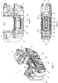
- the Figures 7 - 9 show a third embodiment of the clamping unit (1) for a blow molding machine with a blow molding tool, which is constructed with the clamping unit Figures 1 - 3 largely agrees. Matching components and assemblies of the third embodiment are included provided with the same reference numerals. There are differences from the first embodiment in that the first actuator (13) moves synchronously with the first mold carrier (4) and the second actuator (14) moves synchronously with the second mold carrier (5). In the representations Figures 7 - 9 The tool halves (2,3) are not shown in order to better show the components required for the synchronous movement.
- the locking unit (1) has a base frame which has side cheeks (9) arranged at a parallel distance from one another, on the upper edge of which a longitudinal guide (8) is arranged.
- the first and second mold carriers (4,5) and the drive (7) are connected to guide elements which are displaceably arranged on the longitudinal guides (8).
- first actuator (13) and the second actuator (14) are movably arranged on the closing unit (1) along additional stationary longitudinal guides (23).
- the stationary longitudinal guides (23) are arranged at a parallel distance from one another in the space between the side cheeks (9) and the frame elements (6) on a support structure (24) which is attached to the base frame of the locking unit (1) on the bottom side.
- the first coupling (19) transmits the movement of the first mold carrier (4) to the first actuator (13) and the second coupling (20) transmits the movement of the second mold carrier (5) to the second actuator (14).
- a first and a second guide carriage (25, 26) are provided, which are slidably guided on the additional longitudinal guides (23) arranged at a parallel distance are.
- the first actuator (13) extends vertically upwards from the first guide carriage (25) and the second actuator (14) extends vertically upwards from the second guide carriage (26).
- the first coupling (19) comprises an angle profile which is fastened on the one hand to the first mold carrier (4) and on the other hand to the first actuator (13).
- the second coupling (20) comprises an angle profile which is fastened on the one hand to the second mold carrier (5) and on the other hand to the second actuator (14).
- the actuators (13,14) arranged on the guide carriages (25,26) are moved synchronously.
- the first actuator (13) and the second actuator (14) can each be releasably connected to the underside of the associated lower mold part (2.2,3.2) via the switchable clutch (15, 16).
Landscapes
- Engineering & Computer Science (AREA)
- Manufacturing & Machinery (AREA)
- Mechanical Engineering (AREA)
- Moulds For Moulding Plastics Or The Like (AREA)
- Blow-Moulding Or Thermoforming Of Plastics Or The Like (AREA)
Claims (12)
- Unité de fermeture pour une machine de moulage par soufflage, au moins un outil de moulage par soufflage avec des moitiés d'outil en deux parties (2, 3) étant apte à être utilisé dans la machine de moulage par soufflage, qui, à l'état fermé des deux moitiés d'outil (2, 3), délimite une cavité de moulage avec des contre-dépouilles, et l'unité de fermeture (1) comprenant un premier et un deuxième supports de moule (4, 5), sur lesquels l'outil de moulage par soufflage est apte à être disposé et fixé de manière amovible, et une partie inférieure de moule (2.2, 3.3) de la moitié de moule, c'est-à-dire la moitié de fond inférieure, étant apte à être abaissée par rapport à une partie supérieure de moule (2.1, 3. 1) de la moitié de moule, et dans laquelle les deux moitiés de moule (2, 3) sont aptes à être déplacées en va-et-vient entre un état ouvert et un état fermé dans une première direction de déplacement (17), l'unité de fermeture (1) comprenant au moins un premier actionneur (13) et au moins un deuxième actionneur (14), la partie inférieure de moule (2.2, 3.2) de chaque moitié de moule étant apte à être déplacée en va-et-vient par rapport à la partie supérieure de moule (2.1, 3.1) au moyen de l'au moins un premier actionneur (13) ou au moyen de l'au moins un deuxième actionneur (14) entre un état ouvert et un état fermé dans une deuxième direction de déplacement (18) qui est différente de la première direction de déplacement (17), caractérisée en ce que- les actionneurs (13, 14) sont disposés sur l'unité de fermeture (1) et restent sur l'unité de fermeture (1) lors d'un changement d'outil de moulage par soufflage, et- l'une des deux parties inférieures de moule (2.2, 3.2) est apte à être reliée de manière amovible à la sortie de l'au moins un premier actionneur (13) et l'autre des deux parties inférieures de moule (2.2, 3.2) est apte à être reliée de manière amovible à une sortie de l'au moins un deuxième actionneur (14), de sorte que le changement de l'outil de moulage par soufflage est simplifié, et- l'au moins un premier actionneur (13) et l'au moins un deuxième actionneur (14) sont disposés sur l'unité de fermeture (1) de manière mobile l'un par rapport à l'autre dans la première direction de mouvement (17).
- Unité de fermeture selon la revendication 1, dans laquelle il est prévu un guidage longitudinal fixe (8, 23) pour les actionneurs.
- Unité de fermeture selon la revendication 1 ou 2, les actionneurs étant disposés de manière mobile sur l'unité de fermeture le long d'un guidage longitudinal fixe (8, 23) et une première bielle (19) transmettant le mouvement d'un premier support de moule (4) de l'unité de fermeture (1) à l'au moins un premier actionneur (13) et une deuxième bielle (20) transmettant le mouvement d'un deuxième support de moule (5) de l'unité de fermeture (1) à l'au moins un deuxième actionneur (14).
- Unité de fermeture selon l'une des revendications précédentes 2 ou 3, dans laquelle le premier support de moule (4) et le deuxième support de moule (5) sont guidés en translation le long du guide fixe, et dans laquelle- ce guide fixe est utilisé en tant que le guide longitudinal fixe (8) pour les actionneurs (13, 14), OU- un guidage longitudinal fixe séparé (23) est prévu pour les actionneurs (13, 14).
- Unité de fermeture selon l'une des revendications précédentes, dans laquelle les actionneurs (13, 14) sont agencés de telle sorte qu'ils déplacent la partie inférieure du moule (2.2, 3.2) dans la deuxième direction de déplacement (18) de manière linéaire en va-et-vient entre l'état ouvert et l'état fermé, dans laquelle notamment- les actionneurs (13, 14) sont conçus sous la forme de cylindres de travail actionnés par un fluide, OU- chaque actionneur (13, 14) est un mécanisme à manivelle de poussée qui transforme un mouvement de rotation en un mouvement de poussée oscillant dans la deuxième direction de mouvement (18).
- Unité de fermeture selon l'une des revendications précédentes, dans laquelle les actionneurs (13, 14) sont disposés en dessous des parties inférieures du moule (2.2, 3.2) .
- Unité de fermeture selon l'une des revendications précédentes, dans laquelle une interface définie pour la transmission de force est créée au moyen de la liaison amovible entre l'actionneur (13, 14) et la partie inférieure du moule (2.2, 3.2), afin de pouvoir rapidement détacher et rétablir la liaison entre l'actionneur et la partie inférieure du moule.
- Unité de fermeture selon l'une des revendications précédentes, dans laquelle l'accouplement (15, 16) est réalisé sous la forme d'un accouplement commutable, à force ou à complémentarité de formes, en particulier sous la forme d'un accouplement électromagnétique.
- Unité de fermeture selon la revendication 1 ou 2, dans laquelle l'au moins un premier actionneur (13) se déplace de manière synchrone avec un premier support de moule (4) de l'unité de fermeture (1) et l'au moins un deuxième actionneur (14) se déplace de manière synchrone avec un deuxième support de moule (5) de l'unité de fermeture (1).
- Unité de fermeture selon l'une des revendications précédentes, dans laquelle- l'au moins un premier actionneur (13) est disposé directement sur le premier support de moule (4) et l'au moins un deuxième actionneur (14) est disposé directement sur le deuxième support de moule (5), OU dans laquelle- sur le premier support de moule (4) est disposée une console de fixation (11) pour la fixation indirecte de l'au moins un premier actionneur (13) et sur le deuxième support de moule (5) est disposée une console de fixation (12) pour la fixation indirecte de l'au moins un deuxième actionneur (14).
- Unité de fermeture selon la revendication précédente, dans laquelle les consoles de fixation (11, 12) sont fixées respectivement sur la face inférieure au premier support de moule (4) et au deuxième support de moule (5), et dans laquelle un premier actionneur (13) ou un deuxième actionneur (14) est fixé respectivement sur chaque console de fixation (11, 12) en dessous de la partie inférieure du moule.
- Machine de moulage par soufflage comportant une unité de fermeture (1) selon l'une quelconque des revendications précédentes.
Applications Claiming Priority (2)
| Application Number | Priority Date | Filing Date | Title |
|---|---|---|---|
| DE102019126397.2A DE102019126397B4 (de) | 2019-09-30 | 2019-09-30 | Satz von Aktuatoren für eine Schließeinheit, Schließeinheit für eine Blasformmaschine sowie Blasformmaschine mit einer Schließeinheit |
| PCT/EP2020/077060 WO2021063867A1 (fr) | 2019-09-30 | 2020-09-28 | Unité de fermeture et outil de moulage par soufflage pour une machine de moulage par soufflage |
Publications (3)
| Publication Number | Publication Date |
|---|---|
| EP4003692A1 EP4003692A1 (fr) | 2022-06-01 |
| EP4003692C0 EP4003692C0 (fr) | 2023-09-20 |
| EP4003692B1 true EP4003692B1 (fr) | 2023-09-20 |
Family
ID=72801458
Family Applications (1)
| Application Number | Title | Priority Date | Filing Date |
|---|---|---|---|
| EP20788723.3A Active EP4003692B1 (fr) | 2019-09-30 | 2020-09-28 | Unité de fermeture pour une machine de moulage par soufflage |
Country Status (4)
| Country | Link |
|---|---|
| US (1) | US20220371255A1 (fr) |
| EP (1) | EP4003692B1 (fr) |
| DE (1) | DE102019126397B4 (fr) |
| WO (1) | WO2021063867A1 (fr) |
Families Citing this family (1)
| Publication number | Priority date | Publication date | Assignee | Title |
|---|---|---|---|---|
| CN116261511A (zh) * | 2020-08-20 | 2023-06-13 | 日精Asb机械株式会社 | 吹塑成型装置 |
Family Cites Families (16)
| Publication number | Priority date | Publication date | Assignee | Title |
|---|---|---|---|---|
| US3499071A (en) * | 1967-06-19 | 1970-03-03 | Procter & Gamble | Apparatus for in-mold removal of flash |
| US3753641A (en) | 1969-12-22 | 1973-08-21 | Continental Can Co | Mold for articles having undercut portions |
| US3806300A (en) * | 1971-05-27 | 1974-04-23 | Ethyl Dev Corp | Apparatus for forming the neck on a plastic container |
| US3910742A (en) * | 1972-01-14 | 1975-10-07 | Ethyl Dev Corp | Apparatus for removing waste material from a plastic article |
| DE3613543C1 (de) * | 1986-04-22 | 1986-12-18 | Fried. Krupp Gmbh, 4300 Essen | Schnellspanneinheit für eine Blasform |
| US5026268A (en) | 1990-03-30 | 1991-06-25 | Zarn, Inc. | Apparatus for blow molding an article with compression molded areas |
| US5227114A (en) * | 1992-07-16 | 1993-07-13 | The Lerio Corporation | Process for manufacturing containers with thickened flanges |
| JPH0825469A (ja) * | 1994-07-19 | 1996-01-30 | Tahara:Kk | 中空成形機の金型構造 |
| EP1612031B1 (fr) * | 2004-07-01 | 2006-11-15 | Kautex Maschinenbau GmbH | Procédé et appareil pour la fabrication d'articles creux en plastique |
| US7754138B1 (en) * | 2006-07-10 | 2010-07-13 | Akira Kashiwase | Apparatus and method of manufacturing stackable containers |
| DE102009030492B4 (de) * | 2009-06-24 | 2023-06-15 | Kautex Maschinenbau Gmbh | Verfahren zur Herstellung eines Kunststoffartikels sowie Blasformwerkzeug |
| US8377368B2 (en) * | 2009-12-11 | 2013-02-19 | Ti Automotive Technology Center Gmbh | Component mounting arrangement |
| DE102010025937A1 (de) * | 2010-07-02 | 2012-01-05 | Kautex Maschinenbau Gmbh | Verfahren zur Herstellung eines Kunststoffartikels sowie Blasformwerkzeug zur Durchführung des Verfahrens |
| DE102012109499A1 (de) | 2012-10-05 | 2014-04-10 | Kautex Maschinenbau Gmbh | Schließgestell für eine Blasformmaschine und Blasformmaschine |
| FR3011763B1 (fr) * | 2013-10-14 | 2015-12-11 | Sidel Participations | "unite de moulage pour la fabrication de recipients comportant une pince de compensation" |
| DE102019110917A1 (de) * | 2019-04-26 | 2020-10-29 | Kautex Maschinenbau Gmbh | Hydrostatisches Linear-Antriebssystem |
-
2019
- 2019-09-30 DE DE102019126397.2A patent/DE102019126397B4/de active Active
-
2020
- 2020-09-28 WO PCT/EP2020/077060 patent/WO2021063867A1/fr not_active Ceased
- 2020-09-28 US US17/764,885 patent/US20220371255A1/en not_active Abandoned
- 2020-09-28 EP EP20788723.3A patent/EP4003692B1/fr active Active
Also Published As
| Publication number | Publication date |
|---|---|
| DE102019126397A1 (de) | 2021-04-01 |
| EP4003692A1 (fr) | 2022-06-01 |
| US20220371255A1 (en) | 2022-11-24 |
| DE102019126397B4 (de) | 2023-05-25 |
| EP4003692C0 (fr) | 2023-09-20 |
| WO2021063867A1 (fr) | 2021-04-08 |
Similar Documents
| Publication | Publication Date | Title |
|---|---|---|
| AT409243B (de) | Blasformmaschine | |
| EP2311625B1 (fr) | Porte-moule doté d'un dispositif d'entraînement | |
| EP1044784B1 (fr) | Procédé et dispositif de serrage pour moules de soufflage | |
| EP4003692B1 (fr) | Unité de fermeture pour une machine de moulage par soufflage | |
| DE2429223A1 (de) | Kontinuierlich arbeitende rotationsvorrichtung zum formblasen von kunststoffhohlkoerpern | |
| EP1060865A2 (fr) | Procédé et appareil pour ouvrir ou fermer les moules d'une machine de traitement de matière plastique | |
| DE2911143A1 (de) | Verfahren und vorrichtung zur herstellung von hohlkoerpern, insbesondere kunststoff-flaschen | |
| WO2017059930A1 (fr) | Dispositif de moulage par soufflage présentant un accouplement de fond à actionnement automatique et procédé pour le fonctionnement du dispositif associé | |
| DE4438143A1 (de) | Verfahren und Vorrichtung zum Herstellen von geschäumten Kunststoffteilen | |
| DE19922684C2 (de) | Blasformmaschine für das abfallarme Blasen | |
| DE2423503C3 (de) | Vorrichtung zum Herstellen von Hohlkörpern aus thermoplastischem Kunststoff | |
| DE3925859C2 (de) | Blasformmaschine | |
| DE102009051934B3 (de) | Schließeinheit für eine Spritzgießmaschine | |
| DE102009007151B4 (de) | Entgratpresse mit einer Vorrichtung zur Entnahme eines entgrateten Werkstücks, Entnahmevorrichtung für diese Entgratpresse sowie Verfahren zur Entnahme eines entgrateten Werkstücks aus dieser Entgratpresse | |
| DE1920920C3 (de) | GieBerei-Maschine zum Herstellen von Kernen oder Formmasken aus Formsand | |
| EP1614524B1 (fr) | Appareil de soufflage | |
| DE102012100156A1 (de) | Blasformsystem sowie Verfahren zur Blasformung von Hohlkörpern | |
| EP2498972B1 (fr) | Moule de soufflage | |
| DE10224708C1 (de) | Zusammenfallbarer Kern für Spritzwerkzeuge | |
| EP0734837A1 (fr) | Dispositif pour transporter une paraison d'une filière annulaire au moule de soufflage d'une machine de moulage par soufflage | |
| DE102005036429B4 (de) | Vorrichtung zur Innenhochdruck-Umformung von metallischen, hohlkörperförmigen Rohlingen | |
| DE102004013825A1 (de) | Gelenkarmtransportvorrichtung | |
| DE9308467U1 (de) | Blasformmaschine | |
| DE1905267A1 (de) | Vorrichtung zum Herstellen von Hohlkoerpern aus thermoplastischem Kunststoff im Blasverfahren | |
| DE1479449B1 (de) | Vorrichtung zum herstellen von hohlkoerpern aus thermo plastischen kunststoffen im blasverfahren |
Legal Events
| Date | Code | Title | Description |
|---|---|---|---|
| STAA | Information on the status of an ep patent application or granted ep patent |
Free format text: STATUS: UNKNOWN |
|
| STAA | Information on the status of an ep patent application or granted ep patent |
Free format text: STATUS: THE INTERNATIONAL PUBLICATION HAS BEEN MADE |
|
| PUAI | Public reference made under article 153(3) epc to a published international application that has entered the european phase |
Free format text: ORIGINAL CODE: 0009012 |
|
| STAA | Information on the status of an ep patent application or granted ep patent |
Free format text: STATUS: REQUEST FOR EXAMINATION WAS MADE |
|
| 17P | Request for examination filed |
Effective date: 20220222 |
|
| AK | Designated contracting states |
Kind code of ref document: A1 Designated state(s): AL AT BE BG CH CY CZ DE DK EE ES FI FR GB GR HR HU IE IS IT LI LT LU LV MC MK MT NL NO PL PT RO RS SE SI SK SM TR |
|
| STAA | Information on the status of an ep patent application or granted ep patent |
Free format text: STATUS: EXAMINATION IS IN PROGRESS |
|
| 17Q | First examination report despatched |
Effective date: 20220629 |
|
| DAV | Request for validation of the european patent (deleted) | ||
| DAX | Request for extension of the european patent (deleted) | ||
| RIC1 | Information provided on ipc code assigned before grant |
Ipc: B29C 49/04 20060101ALN20230308BHEP Ipc: B29L 31/00 20060101ALI20230308BHEP Ipc: B29C 49/48 20060101ALI20230308BHEP Ipc: B29C 49/56 20060101ALI20230308BHEP Ipc: B29C 49/54 20060101AFI20230308BHEP |
|
| GRAP | Despatch of communication of intention to grant a patent |
Free format text: ORIGINAL CODE: EPIDOSNIGR1 |
|
| STAA | Information on the status of an ep patent application or granted ep patent |
Free format text: STATUS: GRANT OF PATENT IS INTENDED |
|
| INTG | Intention to grant announced |
Effective date: 20230418 |
|
| GRAS | Grant fee paid |
Free format text: ORIGINAL CODE: EPIDOSNIGR3 |
|
| GRAA | (expected) grant |
Free format text: ORIGINAL CODE: 0009210 |
|
| STAA | Information on the status of an ep patent application or granted ep patent |
Free format text: STATUS: THE PATENT HAS BEEN GRANTED |
|
| AK | Designated contracting states |
Kind code of ref document: B1 Designated state(s): AL AT BE BG CH CY CZ DE DK EE ES FI FR GB GR HR HU IE IS IT LI LT LU LV MC MK MT NL NO PL PT RO RS SE SI SK SM TR |
|
| REG | Reference to a national code |
Ref country code: GB Ref legal event code: FG4D Free format text: NOT ENGLISH |
|
| REG | Reference to a national code |
Ref country code: CH Ref legal event code: EP |
|
| REG | Reference to a national code |
Ref country code: IE Ref legal event code: FG4D Free format text: LANGUAGE OF EP DOCUMENT: GERMAN |
|
| REG | Reference to a national code |
Ref country code: DE Ref legal event code: R096 Ref document number: 502020005333 Country of ref document: DE |
|
| U01 | Request for unitary effect filed |
Effective date: 20231020 |
|
| U07 | Unitary effect registered |
Designated state(s): AT BE BG DE DK EE FI FR IT LT LU LV MT NL PT SE SI Effective date: 20231026 |
|
| PG25 | Lapsed in a contracting state [announced via postgrant information from national office to epo] |
Ref country code: GR Free format text: LAPSE BECAUSE OF FAILURE TO SUBMIT A TRANSLATION OF THE DESCRIPTION OR TO PAY THE FEE WITHIN THE PRESCRIBED TIME-LIMIT Effective date: 20231221 |
|
| PG25 | Lapsed in a contracting state [announced via postgrant information from national office to epo] |
Ref country code: RS Free format text: LAPSE BECAUSE OF FAILURE TO SUBMIT A TRANSLATION OF THE DESCRIPTION OR TO PAY THE FEE WITHIN THE PRESCRIBED TIME-LIMIT Effective date: 20230920 Ref country code: NO Free format text: LAPSE BECAUSE OF FAILURE TO SUBMIT A TRANSLATION OF THE DESCRIPTION OR TO PAY THE FEE WITHIN THE PRESCRIBED TIME-LIMIT Effective date: 20231220 Ref country code: HR Free format text: LAPSE BECAUSE OF FAILURE TO SUBMIT A TRANSLATION OF THE DESCRIPTION OR TO PAY THE FEE WITHIN THE PRESCRIBED TIME-LIMIT Effective date: 20230920 Ref country code: GR Free format text: LAPSE BECAUSE OF FAILURE TO SUBMIT A TRANSLATION OF THE DESCRIPTION OR TO PAY THE FEE WITHIN THE PRESCRIBED TIME-LIMIT Effective date: 20231221 |
|
| PG25 | Lapsed in a contracting state [announced via postgrant information from national office to epo] |
Ref country code: IS Free format text: LAPSE BECAUSE OF FAILURE TO SUBMIT A TRANSLATION OF THE DESCRIPTION OR TO PAY THE FEE WITHIN THE PRESCRIBED TIME-LIMIT Effective date: 20240120 |
|
| PG25 | Lapsed in a contracting state [announced via postgrant information from national office to epo] |
Ref country code: ES Free format text: LAPSE BECAUSE OF FAILURE TO SUBMIT A TRANSLATION OF THE DESCRIPTION OR TO PAY THE FEE WITHIN THE PRESCRIBED TIME-LIMIT Effective date: 20230920 |
|
| PG25 | Lapsed in a contracting state [announced via postgrant information from national office to epo] |
Ref country code: SM Free format text: LAPSE BECAUSE OF FAILURE TO SUBMIT A TRANSLATION OF THE DESCRIPTION OR TO PAY THE FEE WITHIN THE PRESCRIBED TIME-LIMIT Effective date: 20230920 Ref country code: RO Free format text: LAPSE BECAUSE OF FAILURE TO SUBMIT A TRANSLATION OF THE DESCRIPTION OR TO PAY THE FEE WITHIN THE PRESCRIBED TIME-LIMIT Effective date: 20230920 Ref country code: IS Free format text: LAPSE BECAUSE OF FAILURE TO SUBMIT A TRANSLATION OF THE DESCRIPTION OR TO PAY THE FEE WITHIN THE PRESCRIBED TIME-LIMIT Effective date: 20240120 Ref country code: ES Free format text: LAPSE BECAUSE OF FAILURE TO SUBMIT A TRANSLATION OF THE DESCRIPTION OR TO PAY THE FEE WITHIN THE PRESCRIBED TIME-LIMIT Effective date: 20230920 Ref country code: CZ Free format text: LAPSE BECAUSE OF FAILURE TO SUBMIT A TRANSLATION OF THE DESCRIPTION OR TO PAY THE FEE WITHIN THE PRESCRIBED TIME-LIMIT Effective date: 20230920 Ref country code: SK Free format text: LAPSE BECAUSE OF FAILURE TO SUBMIT A TRANSLATION OF THE DESCRIPTION OR TO PAY THE FEE WITHIN THE PRESCRIBED TIME-LIMIT Effective date: 20230920 |
|
| REG | Reference to a national code |
Ref country code: CH Ref legal event code: PL |
|
| U21 | Renewal fee for the european patent with unitary effect paid with additional fee |
Year of fee payment: 4 Effective date: 20240325 |
|
| PG25 | Lapsed in a contracting state [announced via postgrant information from national office to epo] |
Ref country code: PL Free format text: LAPSE BECAUSE OF FAILURE TO SUBMIT A TRANSLATION OF THE DESCRIPTION OR TO PAY THE FEE WITHIN THE PRESCRIBED TIME-LIMIT Effective date: 20230920 |
|
| REG | Reference to a national code |
Ref country code: DE Ref legal event code: R097 Ref document number: 502020005333 Country of ref document: DE |
|
| PG25 | Lapsed in a contracting state [announced via postgrant information from national office to epo] |
Ref country code: MC Free format text: LAPSE BECAUSE OF FAILURE TO SUBMIT A TRANSLATION OF THE DESCRIPTION OR TO PAY THE FEE WITHIN THE PRESCRIBED TIME-LIMIT Effective date: 20230920 |
|
| REG | Reference to a national code |
Ref country code: IE Ref legal event code: MM4A |
|
| PG25 | Lapsed in a contracting state [announced via postgrant information from national office to epo] |
Ref country code: IE Free format text: LAPSE BECAUSE OF NON-PAYMENT OF DUE FEES Effective date: 20230928 |
|
| PG25 | Lapsed in a contracting state [announced via postgrant information from national office to epo] |
Ref country code: CH Free format text: LAPSE BECAUSE OF NON-PAYMENT OF DUE FEES Effective date: 20230930 |
|
| PLBE | No opposition filed within time limit |
Free format text: ORIGINAL CODE: 0009261 |
|
| STAA | Information on the status of an ep patent application or granted ep patent |
Free format text: STATUS: NO OPPOSITION FILED WITHIN TIME LIMIT |
|
| PG25 | Lapsed in a contracting state [announced via postgrant information from national office to epo] |
Ref country code: MC Free format text: LAPSE BECAUSE OF FAILURE TO SUBMIT A TRANSLATION OF THE DESCRIPTION OR TO PAY THE FEE WITHIN THE PRESCRIBED TIME-LIMIT Effective date: 20230920 Ref country code: IE Free format text: LAPSE BECAUSE OF NON-PAYMENT OF DUE FEES Effective date: 20230928 Ref country code: CH Free format text: LAPSE BECAUSE OF NON-PAYMENT OF DUE FEES Effective date: 20230930 |
|
| 26N | No opposition filed |
Effective date: 20240621 |
|
| U1K | Transfer of rights of the unitary patent after the registration of the unitary effect |
Owner name: KAUTEX MASCHINENBAU SYSTEM GMBH; DE |
|
| U20 | Renewal fee for the european patent with unitary effect paid |
Year of fee payment: 5 Effective date: 20240925 |
|
| GBPC | Gb: european patent ceased through non-payment of renewal fee |
Effective date: 20240928 |
|
| PG25 | Lapsed in a contracting state [announced via postgrant information from national office to epo] |
Ref country code: GB Free format text: LAPSE BECAUSE OF NON-PAYMENT OF DUE FEES Effective date: 20240928 |
|
| PG25 | Lapsed in a contracting state [announced via postgrant information from national office to epo] |
Ref country code: CY Free format text: LAPSE BECAUSE OF FAILURE TO SUBMIT A TRANSLATION OF THE DESCRIPTION OR TO PAY THE FEE WITHIN THE PRESCRIBED TIME-LIMIT; INVALID AB INITIO Effective date: 20200928 |
|
| PG25 | Lapsed in a contracting state [announced via postgrant information from national office to epo] |
Ref country code: HU Free format text: LAPSE BECAUSE OF FAILURE TO SUBMIT A TRANSLATION OF THE DESCRIPTION OR TO PAY THE FEE WITHIN THE PRESCRIBED TIME-LIMIT; INVALID AB INITIO Effective date: 20200928 |
|
| U20 | Renewal fee for the european patent with unitary effect paid |
Year of fee payment: 6 Effective date: 20250929 |
|
| PG25 | Lapsed in a contracting state [announced via postgrant information from national office to epo] |
Ref country code: TR Free format text: LAPSE BECAUSE OF FAILURE TO SUBMIT A TRANSLATION OF THE DESCRIPTION OR TO PAY THE FEE WITHIN THE PRESCRIBED TIME-LIMIT Effective date: 20230920 |