EP3802157B1 - Système et méthode de détermination de dommages de pneumatiques - Google Patents
Système et méthode de détermination de dommages de pneumatiques Download PDFInfo
- Publication number
- EP3802157B1 EP3802157B1 EP19737232.9A EP19737232A EP3802157B1 EP 3802157 B1 EP3802157 B1 EP 3802157B1 EP 19737232 A EP19737232 A EP 19737232A EP 3802157 B1 EP3802157 B1 EP 3802157B1
- Authority
- EP
- European Patent Office
- Prior art keywords
- motor vehicle
- tire
- wheel
- predefined
- speeds
- Prior art date
- Legal status (The legal status is an assumption and is not a legal conclusion. Google has not performed a legal analysis and makes no representation as to the accuracy of the status listed.)
- Active
Links
Images

Classifications
-
- G—PHYSICS
- G07—CHECKING-DEVICES
- G07C—TIME OR ATTENDANCE REGISTERS; REGISTERING OR INDICATING THE WORKING OF MACHINES; GENERATING RANDOM NUMBERS; VOTING OR LOTTERY APPARATUS; ARRANGEMENTS, SYSTEMS OR APPARATUS FOR CHECKING NOT PROVIDED FOR ELSEWHERE
- G07C5/00—Registering or indicating the working of vehicles
- G07C5/008—Registering or indicating the working of vehicles communicating information to a remotely located station
-
- B—PERFORMING OPERATIONS; TRANSPORTING
- B60—VEHICLES IN GENERAL
- B60C—VEHICLE TYRES; TYRE INFLATION; TYRE CHANGING; CONNECTING VALVES TO INFLATABLE ELASTIC BODIES IN GENERAL; DEVICES OR ARRANGEMENTS RELATED TO TYRES
- B60C11/00—Tyre tread bands; Tread patterns; Anti-skid inserts
- B60C11/24—Wear-indicating arrangements
- B60C11/246—Tread wear monitoring systems
-
- B—PERFORMING OPERATIONS; TRANSPORTING
- B60—VEHICLES IN GENERAL
- B60C—VEHICLE TYRES; TYRE INFLATION; TYRE CHANGING; CONNECTING VALVES TO INFLATABLE ELASTIC BODIES IN GENERAL; DEVICES OR ARRANGEMENTS RELATED TO TYRES
- B60C19/00—Tyre parts or constructions not otherwise provided for
-
- B—PERFORMING OPERATIONS; TRANSPORTING
- B60—VEHICLES IN GENERAL
- B60C—VEHICLE TYRES; TYRE INFLATION; TYRE CHANGING; CONNECTING VALVES TO INFLATABLE ELASTIC BODIES IN GENERAL; DEVICES OR ARRANGEMENTS RELATED TO TYRES
- B60C23/00—Devices for measuring, signalling, controlling, or distributing tyre pressure or temperature, specially adapted for mounting on vehicles; Arrangement of tyre inflating devices on vehicles, e.g. of pumps or of tanks; Tyre cooling arrangements
- B60C23/02—Signalling devices actuated by tyre pressure
- B60C23/04—Signalling devices actuated by tyre pressure mounted on the wheel or tyre
-
- B—PERFORMING OPERATIONS; TRANSPORTING
- B60—VEHICLES IN GENERAL
- B60C—VEHICLE TYRES; TYRE INFLATION; TYRE CHANGING; CONNECTING VALVES TO INFLATABLE ELASTIC BODIES IN GENERAL; DEVICES OR ARRANGEMENTS RELATED TO TYRES
- B60C23/00—Devices for measuring, signalling, controlling, or distributing tyre pressure or temperature, specially adapted for mounting on vehicles; Arrangement of tyre inflating devices on vehicles, e.g. of pumps or of tanks; Tyre cooling arrangements
- B60C23/02—Signalling devices actuated by tyre pressure
- B60C23/04—Signalling devices actuated by tyre pressure mounted on the wheel or tyre
- B60C23/0486—Signalling devices actuated by tyre pressure mounted on the wheel or tyre comprising additional sensors in the wheel or tyre mounted monitoring device, e.g. movement sensors, microphones or earth magnetic field sensors
- B60C23/0488—Movement sensor, e.g. for sensing angular speed, acceleration or centripetal force
-
- B—PERFORMING OPERATIONS; TRANSPORTING
- B60—VEHICLES IN GENERAL
- B60C—VEHICLE TYRES; TYRE INFLATION; TYRE CHANGING; CONNECTING VALVES TO INFLATABLE ELASTIC BODIES IN GENERAL; DEVICES OR ARRANGEMENTS RELATED TO TYRES
- B60C23/00—Devices for measuring, signalling, controlling, or distributing tyre pressure or temperature, specially adapted for mounting on vehicles; Arrangement of tyre inflating devices on vehicles, e.g. of pumps or of tanks; Tyre cooling arrangements
- B60C23/06—Signalling devices actuated by deformation of the tyre, e.g. tyre mounted deformation sensors or indirect determination of tyre deformation based on wheel speed, wheel-centre to ground distance or inclination of wheel axle
- B60C23/061—Signalling devices actuated by deformation of the tyre, e.g. tyre mounted deformation sensors or indirect determination of tyre deformation based on wheel speed, wheel-centre to ground distance or inclination of wheel axle by monitoring wheel speed
-
- B—PERFORMING OPERATIONS; TRANSPORTING
- B60—VEHICLES IN GENERAL
- B60R—VEHICLES, VEHICLE FITTINGS, OR VEHICLE PARTS, NOT OTHERWISE PROVIDED FOR
- B60R16/00—Electric or fluid circuits specially adapted for vehicles and not otherwise provided for; Arrangement of elements of electric or fluid circuits specially adapted for vehicles and not otherwise provided for
- B60R16/02—Electric or fluid circuits specially adapted for vehicles and not otherwise provided for; Arrangement of elements of electric or fluid circuits specially adapted for vehicles and not otherwise provided for electric constitutive elements
- B60R16/023—Electric or fluid circuits specially adapted for vehicles and not otherwise provided for; Arrangement of elements of electric or fluid circuits specially adapted for vehicles and not otherwise provided for electric constitutive elements for transmission of signals between vehicle parts or subsystems
- B60R16/0231—Circuits relating to the driving or the functioning of the vehicle
- B60R16/0232—Circuits relating to the driving or the functioning of the vehicle for measuring vehicle parameters and indicating critical, abnormal or dangerous conditions
- B60R16/0234—Circuits relating to the driving or the functioning of the vehicle for measuring vehicle parameters and indicating critical, abnormal or dangerous conditions related to maintenance or repairing of vehicles
-
- G—PHYSICS
- G01—MEASURING; TESTING
- G01L—MEASURING FORCE, STRESS, TORQUE, WORK, MECHANICAL POWER, MECHANICAL EFFICIENCY, OR FLUID PRESSURE
- G01L5/00—Apparatus for, or methods of, measuring force, work, mechanical power, or torque, specially adapted for specific purposes
- G01L5/0052—Apparatus for, or methods of, measuring force, work, mechanical power, or torque, specially adapted for specific purposes measuring forces due to impact
-
- G—PHYSICS
- G01—MEASURING; TESTING
- G01M—TESTING STATIC OR DYNAMIC BALANCE OF MACHINES OR STRUCTURES; TESTING OF STRUCTURES OR APPARATUS, NOT OTHERWISE PROVIDED FOR
- G01M17/00—Testing of vehicles
- G01M17/007—Wheeled or endless-tracked vehicles
- G01M17/02—Tyres
-
- G—PHYSICS
- G01—MEASURING; TESTING
- G01N—INVESTIGATING OR ANALYSING MATERIALS BY DETERMINING THEIR CHEMICAL OR PHYSICAL PROPERTIES
- G01N3/00—Investigating strength properties of solid materials by application of mechanical stress
- G01N3/32—Investigating strength properties of solid materials by application of mechanical stress by applying repeated or pulsating forces
- G01N3/34—Investigating strength properties of solid materials by application of mechanical stress by applying repeated or pulsating forces generated by mechanical means, e.g. hammer blows
-
- G—PHYSICS
- G07—CHECKING-DEVICES
- G07C—TIME OR ATTENDANCE REGISTERS; REGISTERING OR INDICATING THE WORKING OF MACHINES; GENERATING RANDOM NUMBERS; VOTING OR LOTTERY APPARATUS; ARRANGEMENTS, SYSTEMS OR APPARATUS FOR CHECKING NOT PROVIDED FOR ELSEWHERE
- G07C5/00—Registering or indicating the working of vehicles
- G07C5/08—Registering or indicating performance data other than driving, working, idle, or waiting time, with or without registering driving, working, idle or waiting time
- G07C5/0808—Diagnosing performance data
-
- G—PHYSICS
- G07—CHECKING-DEVICES
- G07C—TIME OR ATTENDANCE REGISTERS; REGISTERING OR INDICATING THE WORKING OF MACHINES; GENERATING RANDOM NUMBERS; VOTING OR LOTTERY APPARATUS; ARRANGEMENTS, SYSTEMS OR APPARATUS FOR CHECKING NOT PROVIDED FOR ELSEWHERE
- G07C5/00—Registering or indicating the working of vehicles
- G07C5/08—Registering or indicating performance data other than driving, working, idle, or waiting time, with or without registering driving, working, idle or waiting time
- G07C5/0816—Indicating performance data, e.g. occurrence of a malfunction
-
- H—ELECTRICITY
- H04—ELECTRIC COMMUNICATION TECHNIQUE
- H04L—TRANSMISSION OF DIGITAL INFORMATION, e.g. TELEGRAPHIC COMMUNICATION
- H04L67/00—Network arrangements or protocols for supporting network services or applications
- H04L67/01—Protocols
- H04L67/10—Protocols in which an application is distributed across nodes in the network
-
- B—PERFORMING OPERATIONS; TRANSPORTING
- B60—VEHICLES IN GENERAL
- B60C—VEHICLE TYRES; TYRE INFLATION; TYRE CHANGING; CONNECTING VALVES TO INFLATABLE ELASTIC BODIES IN GENERAL; DEVICES OR ARRANGEMENTS RELATED TO TYRES
- B60C19/00—Tyre parts or constructions not otherwise provided for
- B60C2019/004—Tyre sensors other than for detecting tyre pressure
-
- B—PERFORMING OPERATIONS; TRANSPORTING
- B60—VEHICLES IN GENERAL
- B60R—VEHICLES, VEHICLE FITTINGS, OR VEHICLE PARTS, NOT OTHERWISE PROVIDED FOR
- B60R16/00—Electric or fluid circuits specially adapted for vehicles and not otherwise provided for; Arrangement of elements of electric or fluid circuits specially adapted for vehicles and not otherwise provided for
- B60R16/02—Electric or fluid circuits specially adapted for vehicles and not otherwise provided for; Arrangement of elements of electric or fluid circuits specially adapted for vehicles and not otherwise provided for electric constitutive elements
- B60R16/023—Electric or fluid circuits specially adapted for vehicles and not otherwise provided for; Arrangement of elements of electric or fluid circuits specially adapted for vehicles and not otherwise provided for electric constitutive elements for transmission of signals between vehicle parts or subsystems
- B60R16/0231—Circuits relating to the driving or the functioning of the vehicle
- B60R16/0232—Circuits relating to the driving or the functioning of the vehicle for measuring vehicle parameters and indicating critical, abnormal or dangerous conditions
Definitions
- the present invention relates to a system and a method for detecting potential damages to tires of motor vehicles due to impacts against/on obstacles.
- an impact of a wheel of a motor vehicle against/on an obstacle can cause a damage to the tire of the wheel, in particular to the carcass (i.e., the casing) of the tire.
- a damaged tire e.g., a tire with some damaged cords
- a damaged tire e.g., a tire with some damaged cords
- DE 10 2016 105 281 A1 relates to a wheel impact sensing and driver warning system.
- DE 10 2016 105 281 A1 discloses a wheel impact sensing system of a vehicle, which wheel impact sensing system includes:
- EP 1 457 388 A1 discloses a method and apparatus for estimating road surface state and tire running state.
- the frequency of an information signal indicative of the vibration of a wheel detected by an acceleration sensor mounted to a wheel, or the frequency of an information signal indicative of a change in the pressure of a gas in a tire detected by a pressure sensor installed in the tire is analyzed by frequency analyzing means.
- the band value of the obtained vibration spectrum or pressure change spectrum is detected, and a vibration level or pressure change level at the detected frequency band is compared with a vibration level table showing the relationship between road friction coefficient and vibration level stored in vibration level storage means, or a pressure change level table showing the relationship between road friction coefficient and pressure change level stored in pressure change level storage means, to estimate a road friction coefficient.
- EP 2 586 629 A1 discloses a method for determining internal failures, such as separations, of a tire.
- radial acceleration signals of a tire during vehicular travel are detected by an acceleration sensor attached to the inner surface of the tire at the axial center of the tread.
- a frequency analysis is performed on the radial acceleration signals to obtain a frequency spectrum.
- a band value is calculated of a specific frequency band within the range of 100 Hz - 400 Hz, which includes the frequency of the second lowest peak of the peaks appearing in the frequency spectrum. Then a check is made to see whether or not the difference between this band value and a predetermined band value of a normal tire exceeds a threshold value. If said threshold value is exceeded, it is determined that an internal failure, such as a separation, is present in the tire.
- WO 2018/005972 A1 discloses a computer-based method to facilitate detecting wheel imbalance, a tire pressure problem, or excessive tread wear on tires of a moving vehicle.
- the method according to WO 2018/005972 A1 includes: collecting data that represents vibration that results, at least in part, from the vehicle's motion; and determining, with a computer-based processor, whether the moving vehicle has wheel imbalance, a tire pressure problem, and/or excessive tire tread wear based at least in part on the collected vibration data (and possibly other data).
- the collected data can be processed either locally by a mobile personal computing device, or remotely, e.g., in the cloud (in this latter case, the collected data is transmitted to a remote processing system that performs data processing and user notification).
- Object of the present invention is that of providing a technology for performing tire damage detection in a more efficient and reliable way than currently known tire damage detection technologies.
- the present invention concerns a tire damage detection system as defined in independent device claim 1.
- the Applicant has carried out an in-depth study in order to conceive and develop an innovative tire damage detection technology with improved efficiency and reliability with respect to the existing solutions.
- the Applicant has performed several tests with different obstacles (e.g., sidewalks, speed bumps and potholes) at different motor vehicle speeds (e.g., from 40 km/h up to 90 km/h), wherein, for each test, motor vehicle speeds and wheel speeds have been acquired/measured.
- Figure 1 shows examples of wheel speeds acquired/measured during the performed tests in case of impacts against/on obstacles, such as sidewalks and speed bumps, at different motor vehicle speeds.
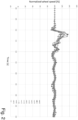
- FIG. 2 shows examples of normalized wheel speeds computed during the performed tests in case of impacts against/on obstacles, such as sidewalks and speed bumps, at different motor vehicle speeds.
- the normalized wheel speed assumes a local minimum value and then a local maximum value.
- the Applicant has observed an "opposite" behavior of the normalized wheel speed, namely the presence, at first, of a local maximum value and, then, of a local minimum value.
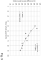
- the Applicant has inferred that the presence of two successive opposite peaks of the normalized wheel speed is indicative of an impact of the wheel against/on an obstacle. Additionally, the Applicant has also noticed that the time distance between two successive opposite peaks of the normalized wheel speed, which are indicative of an impact of the wheel against/on an obstacle, decreases as the motor vehicle speed increases.
- Figure 3 shows examples of relative peak-to-peak differences in the normalized wheel speed as a function of the motor vehicle speed.
- the Applicant has conceived a tire damage detection method including a preliminary step and a tire damage detection step, wherein the preliminary step comprises:
- Figure 4 schematically illustrates (in particular, by means of a block diagram) a functional architecture of a tire damage detection system (denoted as a whole by 1) according to a preferred embodiment of the present invention.
- the tire damage detection system 1 includes:
- v N1 t k v W t k * 100 / v V t k , where v N1 (t k ), v W (t k ) and v V (t k ) denote, respectively, the first normalized wheel speed, the wheel speed and the motor vehicle speed at said generic time instant t k .
- the predefined tire damage model includes a set of first predefined thresholds related to different motor vehicle speed values and a set of first predefined time lengths related to different motor vehicle speed values (wherein said first predefined thresholds and said first predefined time lengths are conveniently determined in the preliminary step).
- the processing device/system 12 is preferably programmed to:
- the actual first predefined threshold and the actual first predefined time length used by the processing device/system 12 for, respectively, the tire damage detection and the first sliding time window are selected, by said processing device/system 12, depending on the actual motor vehicle speed value.
- the tire damage detection may be conveniently based also on tire inflation pressure (in fact, the risk of damage to a tire increases as the tire inflation pressure decreases).
- the acquisition device 11 is conveniently configured to:
- the first predefined thresholds are conveniently related to different motor vehicle speed values and different tire inflation pressure values
- the processing device/system 12 is conveniently configured to receive, from the acquisition device 11, also the quantities indicative of the tire inflation pressure, and is conveniently programmed to select one of the first predefined thresholds depending on the motor vehicle speed and the tire inflation pressure.
- the actual first predefined threshold used by the processing device/system 12 for the tire damage detection is selected, by said processing device/system 12, depending on the actual motor vehicle speed value and the actual tire inflation pressure value.
- v N2 t k v W t k * 100 / v A t k
- v N2 (t k ) and v W (t k ) denote, respectively, the second normalized wheel speed and the wheel speed at the generic time instant t k
- v A (t k ) denotes an average wheel speed associated with said generic time instant t k .
- the average wheel speed v A (t k ) may be computed as an average of a plurality of wheel speed values at time instants that may precede and/or follow the generic time instant t k , wherein said plurality of wheel speed values may also comprise the wheel speed value at the generic time instant t k .
- the predefined tire damage model includes a set of second predefined thresholds related to different average wheel speed values and a set of second predefined time lengths related to different average wheel speed values (wherein said second predefined thresholds and said second predefined time lengths are conveniently determined in the preliminary step).
- the processing device/system 12 is preferably programmed to:
- the tire damage detection may be conveniently based also on tire inflation pressure.
- the acquisition device 11 is conveniently configured to:
- the second predefined thresholds are conveniently related to different average wheel speed values and different tire inflation pressure values
- the processing device/system 12 is conveniently configured to receive, from the acquisition device 11, also the quantities indicative of the tire inflation pressure, and is conveniently programmed to select one of the second predefined thresholds depending on the average wheel speed and the tire inflation pressure.
- the tire damage detection may be conveniently based also on tire inflation pressure.
- the acquisition device 11 is conveniently configured to:
- the third predefined thresholds are conveniently related to different reference wheel speed values and different tire inflation pressure values
- the processing device/system 12 is conveniently configured to receive, from the acquisition device 11, also the quantities indicative of the tire inflation pressure, and is conveniently programmed to select one of the third predefined thresholds depending on the given reference wheel speed value and the tire inflation pressure.
- the acquisition device 11 may be conveniently configured to produce the quantities indicative of the wheel speed by sampling the signal indicative of said speed acquired from the vehicle bus 20 with a sampling frequency equal to or higher than 50 Hz, preferably equal to or higher than 100 Hz.
- the acquisition device 11 may be conveniently configured to produce the quantities indicative of the motor vehicle speed by sampling the signal indicative of said speed acquired from the vehicle bus 20 with the same sampling frequency as the one used for the wheel speed, or with a lower sampling frequency (e.g., 5 or 10 Hz).
- the tire damage detection system 1 further includes a notification device 13 configured to, if a potential damage to the tire of the wheel of the motor vehicle is detected by the processing device/system 12, inform a user associated with said motor vehicle (e.g., a driver and/or an owner thereof) of the potential damage detected.
- a notification device 13 configured to, if a potential damage to the tire of the wheel of the motor vehicle is detected by the processing device/system 12, inform a user associated with said motor vehicle (e.g., a driver and/or an owner thereof) of the potential damage detected.
- the tire damage detection system 1 may be conveniently configured to perform the tire damage detection for each wheel of the motor vehicle. In fact, to this end:
- processing device/system 12 may store:
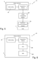
- FIGS 5 and 6 schematically illustrate two specific preferred embodiments of the tire damage detection system 1.
- the cloud computing system 12A is programmed to, if it detects a potential damage to a tire of a wheel of the motor vehicle 2, send a damage notification to the electronic communication device 13A that provides the user 3 with said damage notification.
- the notification device 13 may conveniently be a smartphone or tablet on which a software application (i.e., a so-called app) is installed, which app is configured to receive, from the cloud computing system 12A, a push notification indicating a detected potential damage.
- a software application i.e., a so-called app
- Other types of damage notification may be also used, such as SMS messages, email messages or, more in general, messages of text and/or audio and/or image and/or video and/or multimedia type(s).
- cloud computing system 12A may be advantageously used to provide many motor vehicles 2 and, hence, many users 3 with a tire damage detection service.
- the ECU 12B may conveniently inform a driver of the motor vehicle 2 of a detected potential damage to a tire of a wheel of said motor vehicle 2 via a graphical and/or sound alert produced by the HMI 13B (which, thence, may conveniently comprise a screen and/or a graphical/sound warning indicator).
- the ECU 12B may conveniently be an ECU specifically dedicated to the tire damage detection, or an ECU dedicated to several tasks including also the tire damage detection.
- the HMI 13B may conveniently be a HMI specifically dedicated to the tire damage detection, or a HMI dedicated to several tasks including also the tire damage detection (e.g., a HMI of an onboard infotelematics and/or driver assistance system).
- the tire damage detection step comprises operating the tire damage detection system 1 to detect potential damages to one or more tires of the motor vehicle 2.
- the preliminary step may be carried out according to three preferred implementations corresponding to the three preferred implementations of the tire damage detection step.
- said preliminary step comprises:
- said preliminary step comprises:
- said preliminary step comprises:
- said preliminary step may further comprise:
- the tire damage detection system and method according to the present invention allow performing a real-time, extremely efficient and highly reliable tire damage detection.
- the present invention allows also tuning tire damage detection reliability according to a desired reliability degree.
- many different reliability levels can be chosen and, hence, implemented for the tire damage detection.
- a single tire damage model could be determined in the preliminary step and then used in the tire damage detection step for all tire models and all motor vehicles.
- a respective tire damage model may be determined in the preliminary step for each tire model (thereby taking account of specific tire features, such as specific tire dimensions) and then used in the tire damage detection step for motor vehicles fitted with said tire model.
- tire damage detection reliability even different tire damage models can be determined for each tire model (e.g., to take account of different positions, such as front/rear and/or right/left) and then selectively used in the tire damage detection step for motor vehicles fitted with said tire model. Additionally, further reliability improvements might be obtained by taking account also of specific features of different motor vehicles and/or of geometrical features of different obstacles.
- the tire damage model(s) may be advantageously updated in the tire damage detection step based on false positive errors and false negative errors (i.e., detected potential damages that do not correspond to actual damages to tires, and actual damages to tires that are not detected), thereby improving tire damage detection reliability.
- false positive errors and false negative errors i.e., detected potential damages that do not correspond to actual damages to tires, and actual damages to tires that are not detected
- the driver could take a picture of the damaged tire by means of his/her smartphone/tablet and then send the picture to a server dedicated to receiving user feedbacks.
- the present invention allows performing a real-time, extremely efficient and highly reliable tire damage detection. More specifically, the present invention allows carrying out tire damage detection in a more efficient and reliable way than currently known tire damage detection technologies.
- the present invention allows tuning tire damage detection reliability according to a desired reliability degree.
Landscapes
- Engineering & Computer Science (AREA)
- Mechanical Engineering (AREA)
- Physics & Mathematics (AREA)
- General Physics & Mathematics (AREA)
- General Health & Medical Sciences (AREA)
- Pathology (AREA)
- Analytical Chemistry (AREA)
- Biochemistry (AREA)
- Life Sciences & Earth Sciences (AREA)
- Health & Medical Sciences (AREA)
- Immunology (AREA)
- Chemical & Material Sciences (AREA)
- Computer Networks & Wireless Communication (AREA)
- Signal Processing (AREA)
- Automation & Control Theory (AREA)
- Tires In General (AREA)
- Measuring Fluid Pressure (AREA)
- Arrangements For Transmission Of Measured Signals (AREA)
- Investigating Or Analyzing Materials By The Use Of Ultrasonic Waves (AREA)
Claims (5)
- Système de détection d'endommagement de pneumatique (1, 1A) comportant un dispositif d'acquisition (11), un système de traitement (12, 12A) et un dispositif de notification (13, 13A) ;dans lequel le dispositif d'acquisition (11) est :• installé à bord d'un véhicule à moteur (2) équipé de deux roues ou plus dotées de pneumatiques ;• couplé à un bus de véhicule (20) du véhicule à moteur (2) ; et• configuré pour- acquérir, à partir du bus de véhicule (20), des signaux indiquant des vitesses du véhicule à moteur (2) et d'une roue dudit véhicule à moteur (2) et- émettre en sortie des grandeurs indiquant les vitesses du véhicule à moteur (2) et de la roue de celui-ci ;dans lequel le système de traitement (12, 12A) est :• configuré pour stocker un modèle d'endommagement de pneumatique prédéfini et pour recevoir à partir du dispositif d'acquisition (11), les grandeurs indiquant les vitesses du véhicule à moteur (2) et de la roue dudit véhicule à moteur (2) ; et• programmé pour- calculer, sur la base des grandeurs indiquant les vitesses du véhicule à moteur (2) et de la roue dudit véhicule à moteur (2), une vitesse de roue normalisée indiquant un rapport de la vitesse de roue à la vitesse de véhicule à moteur, et- détecter un endommagement potentiel d'un pneumatique de la roue du véhicule à moteur (2) sur la base du modèle d'endommagement de pneumatique prédéfini et de la vitesse de roue normalisée ;dans lequel le dispositif de notification (13, 13A) est configuré pour, si un endommagement potentiel du pneumatique de la roue du véhicule à moteur (2) est détecté par le système de traitement (12, 12A), signaler l'endommagement potentiel détecté à un utilisateur (3) associé au véhicule à moteur (2) ;dans lequel le système de traitement (12) est un système informatique en nuage (12A) qui est connecté sans fil et à distance au dispositif d'acquisition (11) ; dans lequel le dispositif de notification (13) est un dispositif de communication électronique (13A) associé à l'utilisateur (3) et connecté à distance au système informatique en nuage (12A) par l'intermédiaire d'un ou plusieurs réseaux câblés et/ou sans fil ;caractérisé en ce que le modèle d'endommagement de pneumatique prédéfini comporte un ensemble de seuils prédéfinis relatifs à différentes valeurs de vitesse de véhicule à moteur et un ensemble de longueurs temporelles prédéfinies relatives à différentes valeurs de vitesse de véhicule à moteur ;dans lequel le système de traitement (12, 12A) est programmé pour :• choisir un des seuils prédéfinis et une des longueurs temporelles prédéfinies en fonction de la vitesse de véhicule à moteur ;• analyser la vitesse de roue normalisée au moyen d'une fenêtre temporelle glissante ayant la longueur temporelle prédéfinie choisie ;• détecter une valeur maximale et une valeur minimale de la vitesse de roue normalisée au sein de la fenêtre temporelle glissante ; et• détecter un endommagement potentiel du pneumatique de la roue du véhicule à moteur (2) si une différence entre lesdites valeurs maximale et minimale dépasse le seuil prédéfini choisi.
- Système de détection d'endommagement de pneumatique selon la revendication 1, dans lequel le dispositif d'acquisition (11) est configuré pour :• acquérir également, à partir du bus de véhicule (20), un signal indicatif d'une pression de gonflage de pneumatique du pneumatique de la roue du véhicule à moteur (2) ; et• émettre en sortie des grandeurs indicatives de ladite pression de gonflage de pneumatique ;dans lequel les seuils prédéfinis sont relatifs à différentes valeurs de vitesse de véhicule à moteur et à différentes valeurs de pression de gonflage de pneumatique ;et dans lequel le système de traitement (12, 12A) est configuré pour recevoir également, à partir du dispositif d'acquisition (11), les grandeurs indiquant la pression de gonflage de pneumatique, et est programmé pour choisir l'un des seuils prédéfinis en fonction de la vitesse de véhicule à moteur et de la pression de gonflage de pneumatique.
- Procédé de détection d'endommagement de pneumatique comportant une étape préliminaire et une étape de détection d'endommagement de pneumatique ; dans lequel ladite étape de détection d'endommagement de pneumatique comprend le fonctionnement du système de détection d'endommagement de pneumatique (1, 1A) selon la revendication 1 ou 2 ; et dans lequel ladite étape préliminaire comprend :• la réalisation de tests impliquant le fait de tester des impacts de pneumatique contre/sur des obstacles différents à différentes vitesses de véhicule automobile ;• la mesure/l'acquisition de vitesses de roue et de véhicule à moteur relatives aux tests pendant les tests réalisés ;• le calcul de vitesses de roue normalisées relatives aux tests sur la base des vitesses de roue et de véhicule à moteur relatives aux tests ; et• la détermination du modèle d'endommagement de pneumatique prédéfini à utiliser par le système de détection d'endommagement de pneumatique (1, 1A) dans l'étape de détection d'endommagement de pneumatique en fonction des vitesses de roue normalisées relatives aux tests et des vitesses de véhicule à moteur relatives aux tests qui correspondent aux impacts de pneumatique de test.
- Produit programme informatique comprenant une ou plusieurs parties de code de logiciel et/ou de micrologiciel qui sont :• chargeables sur un système informatique en nuage (12A) conçu pour stocker un modèle d'endommagement de pneumatique prédéfini qui comporte un ensemble de seuils prédéfinis relatifs à différentes valeurs de vitesse de véhicule à moteur et un ensemble de longueurs temporelles prédéfinies relatives à différentes valeurs de vitesse de véhicule à moteur, et pour recevoir des grandeurs indiquant des vitesses d'un véhicule à moteur (2) et d'une roue dudit véhicule à moteur (2) ; et• de nature à amener, lorsqu'il est chargé, ledit système informatique en nuage (12A) à exécuter les étapes suivantes :- le calcul, sur la base des grandeurs indiquant les vitesses du véhicule à moteur (2) et de la roue dudit véhicule à moteur (2), d'une vitesse de roue normalisée indiquant un rapport de la vitesse de roue à la vitesse de véhicule à moteur ;- la détection d'un endommagement potentiel d'un pneumatique de la roue du véhicule à moteur (2) sur la base du modèle d'endommagement de pneumatique prédéfini et de la vitesse de roue normalisée ;- le choix d'un des seuils prédéfinis et d'une des longueurs temporelles prédéfinies en fonction de la vitesse de véhicule à moteur ;- l'analyse de la vitesse de roue normalisée au moyen d'une fenêtre temporelle glissante ayant la longueur temporelle prédéfinie choisie ;- la détection d'une valeur maximale et d'une valeur minimale de la vitesse de roue normalisée au sein de la fenêtre temporelle glissante ; et- la détection d'un endommagement potentiel du pneumatique de la roue du véhicule à moteur (2) si une différence entre lesdites valeurs maximale et minimale dépasse le seuil prédéfini choisi.
- Produit programme informatique comprenant une ou plusieurs parties de code de logiciel et/ou de micrologiciel selon la revendication 4, dans lequel le système informatique en nuage (12A) est en outre configuré pour recevoir des grandeurs indiquant la pression de gonflage de pneumatique ; et de nature à amener, lorsqu'il est chargé, le système informatique en nuage (12A) à choisir l'un des seuils prédéfinis en fonction de la vitesse de véhicule à moteur et de la pression de gonflage de pneumatique.
Applications Claiming Priority (2)
| Application Number | Priority Date | Filing Date | Title |
|---|---|---|---|
| IT102018000005904A IT201800005904A1 (it) | 2018-05-31 | 2018-05-31 | Sistema e metodo di rilevamento di danni a pneumatici |
| PCT/IB2019/054374 WO2019229627A1 (fr) | 2018-05-31 | 2019-05-27 | Système et procédé de détection d'endommagement de pneu |
Publications (2)
| Publication Number | Publication Date |
|---|---|
| EP3802157A1 EP3802157A1 (fr) | 2021-04-14 |
| EP3802157B1 true EP3802157B1 (fr) | 2024-06-26 |
Family
ID=63244910
Family Applications (2)
| Application Number | Title | Priority Date | Filing Date |
|---|---|---|---|
| EP19737233.7A Active EP3802158B1 (fr) | 2018-05-31 | 2019-05-27 | Système de détection de dommage de pneumatiques, et méthode associée |
| EP19737232.9A Active EP3802157B1 (fr) | 2018-05-31 | 2019-05-27 | Système et méthode de détermination de dommages de pneumatiques |
Family Applications Before (1)
| Application Number | Title | Priority Date | Filing Date |
|---|---|---|---|
| EP19737233.7A Active EP3802158B1 (fr) | 2018-05-31 | 2019-05-27 | Système de détection de dommage de pneumatiques, et méthode associée |
Country Status (8)
| Country | Link |
|---|---|
| US (2) | US11908250B2 (fr) |
| EP (2) | EP3802158B1 (fr) |
| JP (2) | JP7019842B2 (fr) |
| CN (2) | CN112533773B (fr) |
| ES (2) | ES2984951T3 (fr) |
| FI (2) | FI3802157T3 (fr) |
| IT (1) | IT201800005904A1 (fr) |
| WO (2) | WO2019229628A1 (fr) |
Families Citing this family (4)
| Publication number | Priority date | Publication date | Assignee | Title |
|---|---|---|---|---|
| IT201800005907A1 (it) * | 2018-05-31 | 2019-12-01 | Sistema e metodo di rilevamento di danni a pneumatici | |
| IT201800005906A1 (it) * | 2018-05-31 | 2019-12-01 | Sistema e metodo di rilevamento di danni a pneumatici | |
| IT202100019016A1 (it) | 2021-07-19 | 2023-01-19 | Bridgestone Europe Nv Sa | Metodo e sistema per rilevare e localizzare ostacoli/elementi sulla pavimentazione stradale che sono pericolosi o potenzialmente pericolosi per l'integrita' degli pneumatici e/o dei veicoli |
| JP7774142B2 (ja) * | 2022-01-06 | 2025-11-20 | ブリヂストン アメリカズ タイヤ オペレーションズ、 エルエルシー | 包括的なタイヤ健全性モデル化並びにその開発及び実装のためのシステム |
Family Cites Families (26)
| Publication number | Priority date | Publication date | Assignee | Title |
|---|---|---|---|---|
| JP3055293B2 (ja) * | 1992-03-16 | 2000-06-26 | 株式会社デンソー | タイヤ空気圧検知装置 |
| US6278361B1 (en) * | 1999-12-03 | 2001-08-21 | Trw Inc. | System and method for monitoring vehicle conditions affecting tires |
| FR2812394A1 (fr) * | 2000-07-25 | 2002-02-01 | Michelin Soc Tech | Procede d'evaluation de l'autonomie d'un systeme de roulage a plat |
| FR2816887B1 (fr) * | 2000-11-20 | 2003-03-14 | Dufournier Technologies | Procede et dispositif detecteur d'usure des pneumatiques ou bandes de roulement et surfaces ou zones d'usure analogues |
| DE10060392A1 (de) * | 2000-12-05 | 2002-06-20 | Volkswagen Ag | Vorrichtung und Verfahren zur Überwachung des Luftdruckes in den Reifen eines Kraftfahrzeuges |
| DE60205340T2 (de) * | 2001-02-26 | 2006-03-23 | Toyota Jidosha Kabushiki Kaisha, Toyota | Gerät zur reifenzustandabschätzung und gerät zur erfassung eines abnormalen reifenzustandes |
| JP2002248916A (ja) * | 2001-02-26 | 2002-09-03 | Toyota Motor Corp | タイヤ情報取得装置、タイヤ情報取得方法およびタイヤ情報取得プログラム |
| GB2372861B (en) * | 2001-02-28 | 2004-07-28 | Ford Global Tech Inc | Vehicle tyre damage detection |
| JP3960764B2 (ja) * | 2001-08-22 | 2007-08-15 | 住友ゴム工業株式会社 | タイヤ異常検出方法および装置、ならびにタイヤ異常検出プログラム |
| CN1321838C (zh) * | 2001-12-21 | 2007-06-20 | 株式会社普利司通 | 路面状况及轮胎行驶状态的推断方法和装置及利用它们的防滑刹车系统和车辆控制 |
| JP2005084003A (ja) * | 2003-09-11 | 2005-03-31 | Honda Motor Co Ltd | タイヤ空気圧検知装置 |
| KR100782474B1 (ko) * | 2006-11-20 | 2007-12-05 | 한국타이어 주식회사 | 주행 타이어의 충격력 측정장치 |
| FR2930195B1 (fr) * | 2008-04-18 | 2011-04-29 | Michelin Soc Tech | Procede et dispositif de pre-alerte pour vehicule |
| IT1393071B1 (it) * | 2008-10-24 | 2012-04-11 | Pirelli | Metodo e sistema per il controllo dell'usura degli pneumatici di un veicolo |
| JP4979729B2 (ja) | 2009-03-19 | 2012-07-18 | 日立建機株式会社 | タイヤ磨耗判定装置を備えた車両 |
| JP5495971B2 (ja) | 2010-06-24 | 2014-05-21 | 株式会社ブリヂストン | タイヤ内部故障判定方法 |
| JP5347054B1 (ja) * | 2012-09-03 | 2013-11-20 | 株式会社ブリヂストン | タイヤケースライフ予測システム |
| DE102012109670B4 (de) * | 2012-10-11 | 2018-03-08 | Infineon Technologies Ag | System und Verfahren zur Bestimmung der Reifenlaufleistung und Reifenabnutzung |
| JP6227385B2 (ja) * | 2013-11-21 | 2017-11-08 | Ntn株式会社 | 自動車用タイヤの摩耗量検知装置 |
| JP6425881B2 (ja) * | 2013-11-21 | 2018-11-21 | Ntn株式会社 | 自動車用タイヤの異常状態検出装置 |
| US20160280130A1 (en) | 2015-03-25 | 2016-09-29 | GM Global Technology Operations LLC | Wheel impact sensing and driver warning system |
| US10000213B2 (en) * | 2016-03-02 | 2018-06-19 | Ford Global Technologies, Llc | Spare tire detection |
| US9983097B2 (en) * | 2016-06-15 | 2018-05-29 | Ford Global Technologies, Llc | Methods and apparatus for assessing tire health through monitoring effective tire rolling radius |
| US10830908B2 (en) * | 2016-06-30 | 2020-11-10 | Massachusetts Institute Of Technology | Applying motion sensor data to wheel imbalance detection, tire pressure monitoring, and/or tread depth measurement |
| DE102016014960A1 (de) * | 2016-12-15 | 2017-06-01 | Daimler Ag | Vorrichtung zur Reifenkontrolle für ein Fahrzeug |
| FR3065934A1 (fr) * | 2017-05-05 | 2018-11-09 | Compagnie Generale Des Etablissements Michelin | Procede d’exploitation des mesures de pression et de temperature d’un pneumatique d’un vehicule |
-
2018
- 2018-05-31 IT IT102018000005904A patent/IT201800005904A1/it unknown
-
2019
- 2019-05-27 US US17/059,528 patent/US11908250B2/en active Active
- 2019-05-27 ES ES19737232T patent/ES2984951T3/es active Active
- 2019-05-27 US US17/059,531 patent/US12026984B2/en active Active
- 2019-05-27 JP JP2020566689A patent/JP7019842B2/ja active Active
- 2019-05-27 WO PCT/IB2019/054376 patent/WO2019229628A1/fr not_active Ceased
- 2019-05-27 EP EP19737233.7A patent/EP3802158B1/fr active Active
- 2019-05-27 JP JP2020566659A patent/JP7019841B2/ja active Active
- 2019-05-27 FI FIEP19737232.9T patent/FI3802157T3/fi active
- 2019-05-27 ES ES19737233T patent/ES2941514T3/es active Active
- 2019-05-27 FI FIEP19737233.7T patent/FI3802158T3/fi active
- 2019-05-27 WO PCT/IB2019/054374 patent/WO2019229627A1/fr not_active Ceased
- 2019-05-27 EP EP19737232.9A patent/EP3802157B1/fr active Active
- 2019-05-27 CN CN201980050984.5A patent/CN112533773B/zh active Active
- 2019-05-27 CN CN201980050983.0A patent/CN112533772B/zh active Active
Also Published As
| Publication number | Publication date |
|---|---|
| US11908250B2 (en) | 2024-02-20 |
| CN112533773A (zh) | 2021-03-19 |
| EP3802158A1 (fr) | 2021-04-14 |
| CN112533773B (zh) | 2022-10-04 |
| WO2019229628A1 (fr) | 2019-12-05 |
| US20210209867A1 (en) | 2021-07-08 |
| CN112533772A (zh) | 2021-03-19 |
| WO2019229627A1 (fr) | 2019-12-05 |
| JP7019841B2 (ja) | 2022-02-15 |
| EP3802158B1 (fr) | 2022-12-28 |
| ES2941514T3 (es) | 2023-05-23 |
| JP2021524826A (ja) | 2021-09-16 |
| JP7019842B2 (ja) | 2022-02-15 |
| FI3802157T3 (fi) | 2024-07-18 |
| JP2021526096A (ja) | 2021-09-30 |
| IT201800005904A1 (it) | 2019-12-01 |
| FI3802158T3 (fi) | 2023-05-03 |
| EP3802157A1 (fr) | 2021-04-14 |
| US20210260934A1 (en) | 2021-08-26 |
| CN112533772B (zh) | 2022-08-23 |
| US12026984B2 (en) | 2024-07-02 |
| ES2984951T3 (es) | 2024-10-31 |
Similar Documents
| Publication | Publication Date | Title |
|---|---|---|
| EP3856538B1 (fr) | Système et méthode de détermination de dommages de pneumatiques | |
| EP3802157B1 (fr) | Système et méthode de détermination de dommages de pneumatiques | |
| JP2021526098A5 (fr) | ||
| EP3856539B1 (fr) | Système et méthode de détermination de dommages de pneumatique | |
| KR101490854B1 (ko) | 타이어의 공기압 저하를 감지하는 방법 및 장치 |
Legal Events
| Date | Code | Title | Description |
|---|---|---|---|
| STAA | Information on the status of an ep patent application or granted ep patent |
Free format text: STATUS: UNKNOWN |
|
| STAA | Information on the status of an ep patent application or granted ep patent |
Free format text: STATUS: THE INTERNATIONAL PUBLICATION HAS BEEN MADE |
|
| PUAI | Public reference made under article 153(3) epc to a published international application that has entered the european phase |
Free format text: ORIGINAL CODE: 0009012 |
|
| STAA | Information on the status of an ep patent application or granted ep patent |
Free format text: STATUS: REQUEST FOR EXAMINATION WAS MADE |
|
| 17P | Request for examination filed |
Effective date: 20210212 |
|
| AK | Designated contracting states |
Kind code of ref document: A1 Designated state(s): AL AT BE BG CH CY CZ DE DK EE ES FI FR GB GR HR HU IE IS IT LI LT LU LV MC MK MT NL NO PL PT RO RS SE SI SK SM TR |
|
| AX | Request for extension of the european patent |
Extension state: BA ME |
|
| DAV | Request for validation of the european patent (deleted) | ||
| DAX | Request for extension of the european patent (deleted) | ||
| STAA | Information on the status of an ep patent application or granted ep patent |
Free format text: STATUS: EXAMINATION IS IN PROGRESS |
|
| 17Q | First examination report despatched |
Effective date: 20220926 |
|
| RAP3 | Party data changed (applicant data changed or rights of an application transferred) |
Owner name: BRIDGESTONE EUROPE NV/SA |
|
| GRAP | Despatch of communication of intention to grant a patent |
Free format text: ORIGINAL CODE: EPIDOSNIGR1 |
|
| STAA | Information on the status of an ep patent application or granted ep patent |
Free format text: STATUS: GRANT OF PATENT IS INTENDED |
|
| INTG | Intention to grant announced |
Effective date: 20230615 |
|
| GRAJ | Information related to disapproval of communication of intention to grant by the applicant or resumption of examination proceedings by the epo deleted |
Free format text: ORIGINAL CODE: EPIDOSDIGR1 |
|
| STAA | Information on the status of an ep patent application or granted ep patent |
Free format text: STATUS: EXAMINATION IS IN PROGRESS |
|
| INTC | Intention to grant announced (deleted) | ||
| GRAP | Despatch of communication of intention to grant a patent |
Free format text: ORIGINAL CODE: EPIDOSNIGR1 |
|
| STAA | Information on the status of an ep patent application or granted ep patent |
Free format text: STATUS: GRANT OF PATENT IS INTENDED |
|
| INTG | Intention to grant announced |
Effective date: 20240103 |
|
| GRAS | Grant fee paid |
Free format text: ORIGINAL CODE: EPIDOSNIGR3 |
|
| GRAA | (expected) grant |
Free format text: ORIGINAL CODE: 0009210 |
|
| STAA | Information on the status of an ep patent application or granted ep patent |
Free format text: STATUS: THE PATENT HAS BEEN GRANTED |
|
| AK | Designated contracting states |
Kind code of ref document: B1 Designated state(s): AL AT BE BG CH CY CZ DE DK EE ES FI FR GB GR HR HU IE IS IT LI LT LU LV MC MK MT NL NO PL PT RO RS SE SI SK SM TR |
|
| REG | Reference to a national code |
Ref country code: GB Ref legal event code: FG4D |
|
| REG | Reference to a national code |
Ref country code: CH Ref legal event code: EP |
|
| REG | Reference to a national code |
Ref country code: DE Ref legal event code: R096 Ref document number: 602019054208 Country of ref document: DE |
|
| REG | Reference to a national code |
Ref country code: FI Ref legal event code: FGE |
|
| REG | Reference to a national code |
Ref country code: SE Ref legal event code: TRGR |
|
| REG | Reference to a national code |
Ref country code: NL Ref legal event code: FP |
|
| PG25 | Lapsed in a contracting state [announced via postgrant information from national office to epo] |
Ref country code: BG Free format text: LAPSE BECAUSE OF FAILURE TO SUBMIT A TRANSLATION OF THE DESCRIPTION OR TO PAY THE FEE WITHIN THE PRESCRIBED TIME-LIMIT Effective date: 20240626 |
|
| PG25 | Lapsed in a contracting state [announced via postgrant information from national office to epo] |
Ref country code: HR Free format text: LAPSE BECAUSE OF FAILURE TO SUBMIT A TRANSLATION OF THE DESCRIPTION OR TO PAY THE FEE WITHIN THE PRESCRIBED TIME-LIMIT Effective date: 20240626 |
|
| REG | Reference to a national code |
Ref country code: LT Ref legal event code: MG9D |
|
| PG25 | Lapsed in a contracting state [announced via postgrant information from national office to epo] |
Ref country code: GR Free format text: LAPSE BECAUSE OF FAILURE TO SUBMIT A TRANSLATION OF THE DESCRIPTION OR TO PAY THE FEE WITHIN THE PRESCRIBED TIME-LIMIT Effective date: 20240927 |
|
| PG25 | Lapsed in a contracting state [announced via postgrant information from national office to epo] |
Ref country code: LV Free format text: LAPSE BECAUSE OF FAILURE TO SUBMIT A TRANSLATION OF THE DESCRIPTION OR TO PAY THE FEE WITHIN THE PRESCRIBED TIME-LIMIT Effective date: 20240626 |
|
| PG25 | Lapsed in a contracting state [announced via postgrant information from national office to epo] |
Ref country code: NO Free format text: LAPSE BECAUSE OF FAILURE TO SUBMIT A TRANSLATION OF THE DESCRIPTION OR TO PAY THE FEE WITHIN THE PRESCRIBED TIME-LIMIT Effective date: 20240926 Ref country code: LV Free format text: LAPSE BECAUSE OF FAILURE TO SUBMIT A TRANSLATION OF THE DESCRIPTION OR TO PAY THE FEE WITHIN THE PRESCRIBED TIME-LIMIT Effective date: 20240626 Ref country code: HR Free format text: LAPSE BECAUSE OF FAILURE TO SUBMIT A TRANSLATION OF THE DESCRIPTION OR TO PAY THE FEE WITHIN THE PRESCRIBED TIME-LIMIT Effective date: 20240626 Ref country code: GR Free format text: LAPSE BECAUSE OF FAILURE TO SUBMIT A TRANSLATION OF THE DESCRIPTION OR TO PAY THE FEE WITHIN THE PRESCRIBED TIME-LIMIT Effective date: 20240927 Ref country code: BG Free format text: LAPSE BECAUSE OF FAILURE TO SUBMIT A TRANSLATION OF THE DESCRIPTION OR TO PAY THE FEE WITHIN THE PRESCRIBED TIME-LIMIT Effective date: 20240626 Ref country code: RS Free format text: LAPSE BECAUSE OF FAILURE TO SUBMIT A TRANSLATION OF THE DESCRIPTION OR TO PAY THE FEE WITHIN THE PRESCRIBED TIME-LIMIT Effective date: 20240926 |
|
| REG | Reference to a national code |
Ref country code: ES Ref legal event code: FG2A Ref document number: 2984951 Country of ref document: ES Kind code of ref document: T3 Effective date: 20241031 |
|
| REG | Reference to a national code |
Ref country code: AT Ref legal event code: MK05 Ref document number: 1697416 Country of ref document: AT Kind code of ref document: T Effective date: 20240626 |
|
| PG25 | Lapsed in a contracting state [announced via postgrant information from national office to epo] |
Ref country code: PT Free format text: LAPSE BECAUSE OF FAILURE TO SUBMIT A TRANSLATION OF THE DESCRIPTION OR TO PAY THE FEE WITHIN THE PRESCRIBED TIME-LIMIT Effective date: 20241028 |
|
| PG25 | Lapsed in a contracting state [announced via postgrant information from national office to epo] |
Ref country code: PT Free format text: LAPSE BECAUSE OF FAILURE TO SUBMIT A TRANSLATION OF THE DESCRIPTION OR TO PAY THE FEE WITHIN THE PRESCRIBED TIME-LIMIT Effective date: 20241028 |
|
| PG25 | Lapsed in a contracting state [announced via postgrant information from national office to epo] |
Ref country code: PL Free format text: LAPSE BECAUSE OF FAILURE TO SUBMIT A TRANSLATION OF THE DESCRIPTION OR TO PAY THE FEE WITHIN THE PRESCRIBED TIME-LIMIT Effective date: 20240626 |
|
| PG25 | Lapsed in a contracting state [announced via postgrant information from national office to epo] |
Ref country code: EE Free format text: LAPSE BECAUSE OF FAILURE TO SUBMIT A TRANSLATION OF THE DESCRIPTION OR TO PAY THE FEE WITHIN THE PRESCRIBED TIME-LIMIT Effective date: 20240626 |
|
| PG25 | Lapsed in a contracting state [announced via postgrant information from national office to epo] |
Ref country code: AT Free format text: LAPSE BECAUSE OF FAILURE TO SUBMIT A TRANSLATION OF THE DESCRIPTION OR TO PAY THE FEE WITHIN THE PRESCRIBED TIME-LIMIT Effective date: 20240626 Ref country code: IS Free format text: LAPSE BECAUSE OF FAILURE TO SUBMIT A TRANSLATION OF THE DESCRIPTION OR TO PAY THE FEE WITHIN THE PRESCRIBED TIME-LIMIT Effective date: 20241026 |
|
| PG25 | Lapsed in a contracting state [announced via postgrant information from national office to epo] |
Ref country code: CZ Free format text: LAPSE BECAUSE OF FAILURE TO SUBMIT A TRANSLATION OF THE DESCRIPTION OR TO PAY THE FEE WITHIN THE PRESCRIBED TIME-LIMIT Effective date: 20240626 |
|
| PG25 | Lapsed in a contracting state [announced via postgrant information from national office to epo] |
Ref country code: SK Free format text: LAPSE BECAUSE OF FAILURE TO SUBMIT A TRANSLATION OF THE DESCRIPTION OR TO PAY THE FEE WITHIN THE PRESCRIBED TIME-LIMIT Effective date: 20240626 Ref country code: RO Free format text: LAPSE BECAUSE OF FAILURE TO SUBMIT A TRANSLATION OF THE DESCRIPTION OR TO PAY THE FEE WITHIN THE PRESCRIBED TIME-LIMIT Effective date: 20240626 |
|
| PG25 | Lapsed in a contracting state [announced via postgrant information from national office to epo] |
Ref country code: SM Free format text: LAPSE BECAUSE OF FAILURE TO SUBMIT A TRANSLATION OF THE DESCRIPTION OR TO PAY THE FEE WITHIN THE PRESCRIBED TIME-LIMIT Effective date: 20240626 |
|
| PG25 | Lapsed in a contracting state [announced via postgrant information from national office to epo] |
Ref country code: SM Free format text: LAPSE BECAUSE OF FAILURE TO SUBMIT A TRANSLATION OF THE DESCRIPTION OR TO PAY THE FEE WITHIN THE PRESCRIBED TIME-LIMIT Effective date: 20240626 Ref country code: SK Free format text: LAPSE BECAUSE OF FAILURE TO SUBMIT A TRANSLATION OF THE DESCRIPTION OR TO PAY THE FEE WITHIN THE PRESCRIBED TIME-LIMIT Effective date: 20240626 Ref country code: RO Free format text: LAPSE BECAUSE OF FAILURE TO SUBMIT A TRANSLATION OF THE DESCRIPTION OR TO PAY THE FEE WITHIN THE PRESCRIBED TIME-LIMIT Effective date: 20240626 Ref country code: PL Free format text: LAPSE BECAUSE OF FAILURE TO SUBMIT A TRANSLATION OF THE DESCRIPTION OR TO PAY THE FEE WITHIN THE PRESCRIBED TIME-LIMIT Effective date: 20240626 Ref country code: IS Free format text: LAPSE BECAUSE OF FAILURE TO SUBMIT A TRANSLATION OF THE DESCRIPTION OR TO PAY THE FEE WITHIN THE PRESCRIBED TIME-LIMIT Effective date: 20241026 Ref country code: EE Free format text: LAPSE BECAUSE OF FAILURE TO SUBMIT A TRANSLATION OF THE DESCRIPTION OR TO PAY THE FEE WITHIN THE PRESCRIBED TIME-LIMIT Effective date: 20240626 Ref country code: CZ Free format text: LAPSE BECAUSE OF FAILURE TO SUBMIT A TRANSLATION OF THE DESCRIPTION OR TO PAY THE FEE WITHIN THE PRESCRIBED TIME-LIMIT Effective date: 20240626 Ref country code: AT Free format text: LAPSE BECAUSE OF FAILURE TO SUBMIT A TRANSLATION OF THE DESCRIPTION OR TO PAY THE FEE WITHIN THE PRESCRIBED TIME-LIMIT Effective date: 20240626 |
|
| REG | Reference to a national code |
Ref country code: DE Ref legal event code: R097 Ref document number: 602019054208 Country of ref document: DE |
|
| P01 | Opt-out of the competence of the unified patent court (upc) registered |
Free format text: CASE NUMBER: APP_8756/2025 Effective date: 20250220 |
|
| PG25 | Lapsed in a contracting state [announced via postgrant information from national office to epo] |
Ref country code: DK Free format text: LAPSE BECAUSE OF FAILURE TO SUBMIT A TRANSLATION OF THE DESCRIPTION OR TO PAY THE FEE WITHIN THE PRESCRIBED TIME-LIMIT Effective date: 20240626 |
|
| PLBE | No opposition filed within time limit |
Free format text: ORIGINAL CODE: 0009261 |
|
| STAA | Information on the status of an ep patent application or granted ep patent |
Free format text: STATUS: NO OPPOSITION FILED WITHIN TIME LIMIT |
|
| PGFP | Annual fee paid to national office [announced via postgrant information from national office to epo] |
Ref country code: NL Payment date: 20250423 Year of fee payment: 7 |
|
| 26N | No opposition filed |
Effective date: 20250327 |
|
| PGFP | Annual fee paid to national office [announced via postgrant information from national office to epo] |
Ref country code: FI Payment date: 20250423 Year of fee payment: 7 |
|
| PGFP | Annual fee paid to national office [announced via postgrant information from national office to epo] |
Ref country code: DE Payment date: 20250423 Year of fee payment: 7 |
|
| PGFP | Annual fee paid to national office [announced via postgrant information from national office to epo] |
Ref country code: GB Payment date: 20250423 Year of fee payment: 7 Ref country code: ES Payment date: 20250602 Year of fee payment: 7 |
|
| PGFP | Annual fee paid to national office [announced via postgrant information from national office to epo] |
Ref country code: IT Payment date: 20250423 Year of fee payment: 7 |
|
| PGFP | Annual fee paid to national office [announced via postgrant information from national office to epo] |
Ref country code: FR Payment date: 20250423 Year of fee payment: 7 |
|
| PGFP | Annual fee paid to national office [announced via postgrant information from national office to epo] |
Ref country code: CH Payment date: 20250601 Year of fee payment: 7 |
|
| PGFP | Annual fee paid to national office [announced via postgrant information from national office to epo] |
Ref country code: SE Payment date: 20250423 Year of fee payment: 7 |
|
| PG25 | Lapsed in a contracting state [announced via postgrant information from national office to epo] |
Ref country code: LU Free format text: LAPSE BECAUSE OF NON-PAYMENT OF DUE FEES Effective date: 20250527 |
|
| REG | Reference to a national code |
Ref country code: BE Ref legal event code: MM Effective date: 20250531 |
|
| PG25 | Lapsed in a contracting state [announced via postgrant information from national office to epo] |
Ref country code: MC Free format text: LAPSE BECAUSE OF FAILURE TO SUBMIT A TRANSLATION OF THE DESCRIPTION OR TO PAY THE FEE WITHIN THE PRESCRIBED TIME-LIMIT Effective date: 20240626 |
|
| PG25 | Lapsed in a contracting state [announced via postgrant information from national office to epo] |
Ref country code: IE Free format text: LAPSE BECAUSE OF NON-PAYMENT OF DUE FEES Effective date: 20250527 |
|
| PG25 | Lapsed in a contracting state [announced via postgrant information from national office to epo] |
Ref country code: BE Free format text: LAPSE BECAUSE OF NON-PAYMENT OF DUE FEES Effective date: 20250531 |