EP3802254B1 - Planification de trajectoire - Google Patents
Planification de trajectoire Download PDFInfo
- Publication number
- EP3802254B1 EP3802254B1 EP18921078.4A EP18921078A EP3802254B1 EP 3802254 B1 EP3802254 B1 EP 3802254B1 EP 18921078 A EP18921078 A EP 18921078A EP 3802254 B1 EP3802254 B1 EP 3802254B1
- Authority
- EP
- European Patent Office
- Prior art keywords
- drivable area
- vehicle
- trajectory
- determining
- bin
- Prior art date
- Legal status (The legal status is an assumption and is not a legal conclusion. Google has not performed a legal analysis and makes no representation as to the accuracy of the status listed.)
- Active
Links
Images







Classifications
-
- B—PERFORMING OPERATIONS; TRANSPORTING
- B60—VEHICLES IN GENERAL
- B60W—CONJOINT CONTROL OF VEHICLE SUB-UNITS OF DIFFERENT TYPE OR DIFFERENT FUNCTION; CONTROL SYSTEMS SPECIALLY ADAPTED FOR HYBRID VEHICLES; ROAD VEHICLE DRIVE CONTROL SYSTEMS FOR PURPOSES NOT RELATED TO THE CONTROL OF A PARTICULAR SUB-UNIT
- B60W60/00—Drive control systems specially adapted for autonomous road vehicles
- B60W60/001—Planning or execution of driving tasks
- B60W60/0011—Planning or execution of driving tasks involving control alternatives for a single driving scenario, e.g. planning several paths to avoid obstacles
-
- B—PERFORMING OPERATIONS; TRANSPORTING
- B60—VEHICLES IN GENERAL
- B60W—CONJOINT CONTROL OF VEHICLE SUB-UNITS OF DIFFERENT TYPE OR DIFFERENT FUNCTION; CONTROL SYSTEMS SPECIALLY ADAPTED FOR HYBRID VEHICLES; ROAD VEHICLE DRIVE CONTROL SYSTEMS FOR PURPOSES NOT RELATED TO THE CONTROL OF A PARTICULAR SUB-UNIT
- B60W10/00—Conjoint control of vehicle sub-units of different type or different function
- B60W10/04—Conjoint control of vehicle sub-units of different type or different function including control of propulsion units
-
- B—PERFORMING OPERATIONS; TRANSPORTING
- B60—VEHICLES IN GENERAL
- B60W—CONJOINT CONTROL OF VEHICLE SUB-UNITS OF DIFFERENT TYPE OR DIFFERENT FUNCTION; CONTROL SYSTEMS SPECIALLY ADAPTED FOR HYBRID VEHICLES; ROAD VEHICLE DRIVE CONTROL SYSTEMS FOR PURPOSES NOT RELATED TO THE CONTROL OF A PARTICULAR SUB-UNIT
- B60W10/00—Conjoint control of vehicle sub-units of different type or different function
- B60W10/10—Conjoint control of vehicle sub-units of different type or different function including control of change-speed gearings
-
- B—PERFORMING OPERATIONS; TRANSPORTING
- B60—VEHICLES IN GENERAL
- B60W—CONJOINT CONTROL OF VEHICLE SUB-UNITS OF DIFFERENT TYPE OR DIFFERENT FUNCTION; CONTROL SYSTEMS SPECIALLY ADAPTED FOR HYBRID VEHICLES; ROAD VEHICLE DRIVE CONTROL SYSTEMS FOR PURPOSES NOT RELATED TO THE CONTROL OF A PARTICULAR SUB-UNIT
- B60W10/00—Conjoint control of vehicle sub-units of different type or different function
- B60W10/18—Conjoint control of vehicle sub-units of different type or different function including control of braking systems
-
- B—PERFORMING OPERATIONS; TRANSPORTING
- B60—VEHICLES IN GENERAL
- B60W—CONJOINT CONTROL OF VEHICLE SUB-UNITS OF DIFFERENT TYPE OR DIFFERENT FUNCTION; CONTROL SYSTEMS SPECIALLY ADAPTED FOR HYBRID VEHICLES; ROAD VEHICLE DRIVE CONTROL SYSTEMS FOR PURPOSES NOT RELATED TO THE CONTROL OF A PARTICULAR SUB-UNIT
- B60W30/00—Purposes of road vehicle drive control systems not related to the control of a particular sub-unit, e.g. of systems using conjoint control of vehicle sub-units
- B60W30/08—Active safety systems predicting or avoiding probable or impending collision or attempting to minimise its consequences
- B60W30/09—Taking automatic action to avoid collision, e.g. braking and steering
-
- B—PERFORMING OPERATIONS; TRANSPORTING
- B60—VEHICLES IN GENERAL
- B60W—CONJOINT CONTROL OF VEHICLE SUB-UNITS OF DIFFERENT TYPE OR DIFFERENT FUNCTION; CONTROL SYSTEMS SPECIALLY ADAPTED FOR HYBRID VEHICLES; ROAD VEHICLE DRIVE CONTROL SYSTEMS FOR PURPOSES NOT RELATED TO THE CONTROL OF A PARTICULAR SUB-UNIT
- B60W30/00—Purposes of road vehicle drive control systems not related to the control of a particular sub-unit, e.g. of systems using conjoint control of vehicle sub-units
- B60W30/08—Active safety systems predicting or avoiding probable or impending collision or attempting to minimise its consequences
- B60W30/095—Predicting travel path or likelihood of collision
- B60W30/0956—Predicting travel path or likelihood of collision the prediction being responsive to traffic or environmental parameters
-
- B—PERFORMING OPERATIONS; TRANSPORTING
- B60—VEHICLES IN GENERAL
- B60W—CONJOINT CONTROL OF VEHICLE SUB-UNITS OF DIFFERENT TYPE OR DIFFERENT FUNCTION; CONTROL SYSTEMS SPECIALLY ADAPTED FOR HYBRID VEHICLES; ROAD VEHICLE DRIVE CONTROL SYSTEMS FOR PURPOSES NOT RELATED TO THE CONTROL OF A PARTICULAR SUB-UNIT
- B60W30/00—Purposes of road vehicle drive control systems not related to the control of a particular sub-unit, e.g. of systems using conjoint control of vehicle sub-units
- B60W30/14—Adaptive cruise control
- B60W30/143—Speed control
- B60W30/146—Speed limiting
-
- B—PERFORMING OPERATIONS; TRANSPORTING
- B60—VEHICLES IN GENERAL
- B60W—CONJOINT CONTROL OF VEHICLE SUB-UNITS OF DIFFERENT TYPE OR DIFFERENT FUNCTION; CONTROL SYSTEMS SPECIALLY ADAPTED FOR HYBRID VEHICLES; ROAD VEHICLE DRIVE CONTROL SYSTEMS FOR PURPOSES NOT RELATED TO THE CONTROL OF A PARTICULAR SUB-UNIT
- B60W30/00—Purposes of road vehicle drive control systems not related to the control of a particular sub-unit, e.g. of systems using conjoint control of vehicle sub-units
- B60W30/18—Propelling the vehicle
- B60W30/18009—Propelling the vehicle related to particular drive situations
- B60W30/18145—Cornering
-
- B—PERFORMING OPERATIONS; TRANSPORTING
- B60—VEHICLES IN GENERAL
- B60W—CONJOINT CONTROL OF VEHICLE SUB-UNITS OF DIFFERENT TYPE OR DIFFERENT FUNCTION; CONTROL SYSTEMS SPECIALLY ADAPTED FOR HYBRID VEHICLES; ROAD VEHICLE DRIVE CONTROL SYSTEMS FOR PURPOSES NOT RELATED TO THE CONTROL OF A PARTICULAR SUB-UNIT
- B60W30/00—Purposes of road vehicle drive control systems not related to the control of a particular sub-unit, e.g. of systems using conjoint control of vehicle sub-units
- B60W30/18—Propelling the vehicle
- B60W30/18009—Propelling the vehicle related to particular drive situations
- B60W30/18159—Traversing an intersection
-
- B—PERFORMING OPERATIONS; TRANSPORTING
- B60—VEHICLES IN GENERAL
- B60W—CONJOINT CONTROL OF VEHICLE SUB-UNITS OF DIFFERENT TYPE OR DIFFERENT FUNCTION; CONTROL SYSTEMS SPECIALLY ADAPTED FOR HYBRID VEHICLES; ROAD VEHICLE DRIVE CONTROL SYSTEMS FOR PURPOSES NOT RELATED TO THE CONTROL OF A PARTICULAR SUB-UNIT
- B60W30/00—Purposes of road vehicle drive control systems not related to the control of a particular sub-unit, e.g. of systems using conjoint control of vehicle sub-units
- B60W30/18—Propelling the vehicle
- B60W30/18009—Propelling the vehicle related to particular drive situations
- B60W30/18163—Lane change; Overtaking manoeuvres
-
- B—PERFORMING OPERATIONS; TRANSPORTING
- B60—VEHICLES IN GENERAL
- B60W—CONJOINT CONTROL OF VEHICLE SUB-UNITS OF DIFFERENT TYPE OR DIFFERENT FUNCTION; CONTROL SYSTEMS SPECIALLY ADAPTED FOR HYBRID VEHICLES; ROAD VEHICLE DRIVE CONTROL SYSTEMS FOR PURPOSES NOT RELATED TO THE CONTROL OF A PARTICULAR SUB-UNIT
- B60W40/00—Estimation or calculation of non-directly measurable driving parameters for road vehicle drive control systems not related to the control of a particular sub unit, e.g. by using mathematical models
- B60W40/02—Estimation or calculation of non-directly measurable driving parameters for road vehicle drive control systems not related to the control of a particular sub unit, e.g. by using mathematical models related to ambient conditions
- B60W40/04—Traffic conditions
-
- B—PERFORMING OPERATIONS; TRANSPORTING
- B60—VEHICLES IN GENERAL
- B60W—CONJOINT CONTROL OF VEHICLE SUB-UNITS OF DIFFERENT TYPE OR DIFFERENT FUNCTION; CONTROL SYSTEMS SPECIALLY ADAPTED FOR HYBRID VEHICLES; ROAD VEHICLE DRIVE CONTROL SYSTEMS FOR PURPOSES NOT RELATED TO THE CONTROL OF A PARTICULAR SUB-UNIT
- B60W60/00—Drive control systems specially adapted for autonomous road vehicles
- B60W60/001—Planning or execution of driving tasks
-
- B—PERFORMING OPERATIONS; TRANSPORTING
- B60—VEHICLES IN GENERAL
- B60W—CONJOINT CONTROL OF VEHICLE SUB-UNITS OF DIFFERENT TYPE OR DIFFERENT FUNCTION; CONTROL SYSTEMS SPECIALLY ADAPTED FOR HYBRID VEHICLES; ROAD VEHICLE DRIVE CONTROL SYSTEMS FOR PURPOSES NOT RELATED TO THE CONTROL OF A PARTICULAR SUB-UNIT
- B60W60/00—Drive control systems specially adapted for autonomous road vehicles
- B60W60/001—Planning or execution of driving tasks
- B60W60/0015—Planning or execution of driving tasks specially adapted for safety
-
- B—PERFORMING OPERATIONS; TRANSPORTING
- B60—VEHICLES IN GENERAL
- B60W—CONJOINT CONTROL OF VEHICLE SUB-UNITS OF DIFFERENT TYPE OR DIFFERENT FUNCTION; CONTROL SYSTEMS SPECIALLY ADAPTED FOR HYBRID VEHICLES; ROAD VEHICLE DRIVE CONTROL SYSTEMS FOR PURPOSES NOT RELATED TO THE CONTROL OF A PARTICULAR SUB-UNIT
- B60W60/00—Drive control systems specially adapted for autonomous road vehicles
- B60W60/001—Planning or execution of driving tasks
- B60W60/0027—Planning or execution of driving tasks using trajectory prediction for other traffic participants
- B60W60/00274—Planning or execution of driving tasks using trajectory prediction for other traffic participants considering possible movement changes
-
- G—PHYSICS
- G01—MEASURING; TESTING
- G01C—MEASURING DISTANCES, LEVELS OR BEARINGS; SURVEYING; NAVIGATION; GYROSCOPIC INSTRUMENTS; PHOTOGRAMMETRY OR VIDEOGRAMMETRY
- G01C21/00—Navigation; Navigational instruments not provided for in groups G01C1/00 - G01C19/00
- G01C21/26—Navigation; Navigational instruments not provided for in groups G01C1/00 - G01C19/00 specially adapted for navigation in a road network
- G01C21/28—Navigation; Navigational instruments not provided for in groups G01C1/00 - G01C19/00 specially adapted for navigation in a road network with correlation of data from several navigational instruments
-
- G—PHYSICS
- G05—CONTROLLING; REGULATING
- G05D—SYSTEMS FOR CONTROLLING OR REGULATING NON-ELECTRIC VARIABLES
- G05D1/00—Control of position, course, altitude or attitude of land, water, air or space vehicles, e.g. using automatic pilots
- G05D1/02—Control of position or course in two dimensions
- G05D1/021—Control of position or course in two dimensions specially adapted to land vehicles
- G05D1/0287—Control of position or course in two dimensions specially adapted to land vehicles involving a plurality of land vehicles, e.g. fleet or convoy travelling
- G05D1/0289—Control of position or course in two dimensions specially adapted to land vehicles involving a plurality of land vehicles, e.g. fleet or convoy travelling with means for avoiding collisions between vehicles
-
- G—PHYSICS
- G06—COMPUTING OR CALCULATING; COUNTING
- G06V—IMAGE OR VIDEO RECOGNITION OR UNDERSTANDING
- G06V20/00—Scenes; Scene-specific elements
- G06V20/50—Context or environment of the image
- G06V20/56—Context or environment of the image exterior to a vehicle by using sensors mounted on the vehicle
- G06V20/58—Recognition of moving objects or obstacles, e.g. vehicles or pedestrians; Recognition of traffic objects, e.g. traffic signs, traffic lights or roads
-
- G—PHYSICS
- G08—SIGNALLING
- G08G—TRAFFIC CONTROL SYSTEMS
- G08G1/00—Traffic control systems for road vehicles
- G08G1/01—Detecting movement of traffic to be counted or controlled
- G08G1/042—Detecting movement of traffic to be counted or controlled using inductive or magnetic detectors
-
- G—PHYSICS
- G08—SIGNALLING
- G08G—TRAFFIC CONTROL SYSTEMS
- G08G1/00—Traffic control systems for road vehicles
- G08G1/16—Anti-collision systems
-
- G—PHYSICS
- G08—SIGNALLING
- G08G—TRAFFIC CONTROL SYSTEMS
- G08G1/00—Traffic control systems for road vehicles
- G08G1/16—Anti-collision systems
- G08G1/161—Decentralised systems, e.g. inter-vehicle communication
- G08G1/163—Decentralised systems, e.g. inter-vehicle communication involving continuous checking
-
- G—PHYSICS
- G08—SIGNALLING
- G08G—TRAFFIC CONTROL SYSTEMS
- G08G1/00—Traffic control systems for road vehicles
- G08G1/16—Anti-collision systems
- G08G1/165—Anti-collision systems for passive traffic, e.g. including static obstacles, trees
-
- G—PHYSICS
- G08—SIGNALLING
- G08G—TRAFFIC CONTROL SYSTEMS
- G08G1/00—Traffic control systems for road vehicles
- G08G1/16—Anti-collision systems
- G08G1/166—Anti-collision systems for active traffic, e.g. moving vehicles, pedestrians, bikes
-
- G—PHYSICS
- G08—SIGNALLING
- G08G—TRAFFIC CONTROL SYSTEMS
- G08G1/00—Traffic control systems for road vehicles
- G08G1/16—Anti-collision systems
- G08G1/167—Driving aids for lane monitoring, lane changing, e.g. blind spot detection
-
- B—PERFORMING OPERATIONS; TRANSPORTING
- B60—VEHICLES IN GENERAL
- B60W—CONJOINT CONTROL OF VEHICLE SUB-UNITS OF DIFFERENT TYPE OR DIFFERENT FUNCTION; CONTROL SYSTEMS SPECIALLY ADAPTED FOR HYBRID VEHICLES; ROAD VEHICLE DRIVE CONTROL SYSTEMS FOR PURPOSES NOT RELATED TO THE CONTROL OF A PARTICULAR SUB-UNIT
- B60W2554/00—Input parameters relating to objects
- B60W2554/20—Static objects
-
- B—PERFORMING OPERATIONS; TRANSPORTING
- B60—VEHICLES IN GENERAL
- B60W—CONJOINT CONTROL OF VEHICLE SUB-UNITS OF DIFFERENT TYPE OR DIFFERENT FUNCTION; CONTROL SYSTEMS SPECIALLY ADAPTED FOR HYBRID VEHICLES; ROAD VEHICLE DRIVE CONTROL SYSTEMS FOR PURPOSES NOT RELATED TO THE CONTROL OF A PARTICULAR SUB-UNIT
- B60W2554/00—Input parameters relating to objects
- B60W2554/40—Dynamic objects, e.g. animals, windblown objects
- B60W2554/404—Characteristics
- B60W2554/4044—Direction of movement, e.g. backwards
-
- B—PERFORMING OPERATIONS; TRANSPORTING
- B60—VEHICLES IN GENERAL
- B60W—CONJOINT CONTROL OF VEHICLE SUB-UNITS OF DIFFERENT TYPE OR DIFFERENT FUNCTION; CONTROL SYSTEMS SPECIALLY ADAPTED FOR HYBRID VEHICLES; ROAD VEHICLE DRIVE CONTROL SYSTEMS FOR PURPOSES NOT RELATED TO THE CONTROL OF A PARTICULAR SUB-UNIT
- B60W2554/00—Input parameters relating to objects
- B60W2554/40—Dynamic objects, e.g. animals, windblown objects
- B60W2554/404—Characteristics
- B60W2554/4045—Intention, e.g. lane change or imminent movement
-
- B—PERFORMING OPERATIONS; TRANSPORTING
- B60—VEHICLES IN GENERAL
- B60W—CONJOINT CONTROL OF VEHICLE SUB-UNITS OF DIFFERENT TYPE OR DIFFERENT FUNCTION; CONTROL SYSTEMS SPECIALLY ADAPTED FOR HYBRID VEHICLES; ROAD VEHICLE DRIVE CONTROL SYSTEMS FOR PURPOSES NOT RELATED TO THE CONTROL OF A PARTICULAR SUB-UNIT
- B60W2554/00—Input parameters relating to objects
- B60W2554/80—Spatial relation or speed relative to objects
Definitions
- This invention relates to methods and systems for trajectory planning for autonomous vehicles.
- the methods and apparatus described herein may be implemented in any vehicle capable of autonomous or semi-autonomous operation. Although described with reference to a vehicle transportation network, the method and apparatus described herein may include the autonomous vehicle operating in any area navigable by the vehicle.
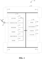
- the transmission 108 receives energy, such as kinetic energy, from the power source 106 and transmits the energy to the wheels 132/134/136/138 to provide a motive force.
- the transmission 108 may be controlled by the controller 114, the vehicle actuator 112, or both.
- the steering unit 110 may be controlled by the controller 114, the vehicle actuator 112, or both and controls the wheels 132/134/136/138 to steer the vehicle.
- the vehicle actuator 112 may receive signals from the controller 114 and may actuate or control the power source 106, the transmission 108, the steering unit 110, or any combination thereof to operate the vehicle 100.
- the location unit 116, the electronic communication unit 118, the processor 120, the memory 122, the user interface 124, the sensor 126, the electronic communication interface 128, or any combination thereof can be integrated in one or more electronic units, circuits, or chips.
- the processor 120 may be operatively coupled with the location unit 116, the memory 122, the electronic communication interface 128, the electronic communication unit 118, the user interface 124, the sensor 126, the powertrain 104, or any combination thereof.
- the processor may be operatively coupled with the memory 122 via a communication bus 130.
- the processor 120 may be configured to execute instructions. Such instructions may include instructions for remote operation, which may be used to operate the vehicle 100 from a remote location, including the operations center.
- the instructions for remote operation may be stored in the vehicle 100 or received from an external source, such as a traffic management center, or server computing devices, which may include cloud-based server computing devices.
- Remote operation was introduced in U.S. provisional patent application Ser. No. 62/633,414, filed February 21, 2018 , and entitled "REMOTE OPERATION EXTENDING AN EXISTING ROUTE TO A DESTINATION.”
- the vehicle 100 may include a trajectory controller.
- the controller 114 may include a trajectory controller.
- the trajectory controller may be operable to obtain information describing a current state of the vehicle 100 and a route planned for the vehicle 100, and, based on this information, to determine and optimize a trajectory for the vehicle 100.
- the trajectory controller outputs signals operable to control the vehicle 100 such that the vehicle 100 follows the trajectory that is determined by the trajectory controller.
- the output of the trajectory controller can be an optimized trajectory that may be supplied to the powertrain 104, the wheels 132/134/136/138, or both.
- the optimized trajectory can be a control input, such as a set of steering angles, with each steering angle corresponding to a point in time or a position.
- the optimized trajectory can be one or more paths, lines, curves, or a combination thereof.
- a vehicle may include units or elements not shown in FIG. 1 , such as an enclosure, a Bluetooth ® module, a frequency modulated (FM) radio unit, a Near-Field Communication (NFC) module, a liquid crystal display (LCD) display unit, an organic light-emitting diode (OLED) display unit, a speaker, or any combination thereof.
- a Bluetooth ® module a frequency modulated (FM) radio unit
- NFC Near-Field Communication
- LCD liquid crystal display
- OLED organic light-emitting diode
- FIG. 2 is a diagram of an example of a portion of a vehicle transportation and communication system 200 in which the aspects, features, and elements disclosed herein may be implemented.
- the vehicle transportation and communication system 200 includes a vehicle 202, such as the vehicle 100 shown in FIG. 1 , and one or more external objects, such as an external object 206, which can include any form of transportation, such as the vehicle 100 shown in FIG. 1 , a pedestrian, cyclist, as well as any form of a structure, such as a building.
- the vehicle 202 may travel via one or more portions of a transportation network 208, and may communicate with the external object 206 via one or more of an electronic communication network 212.
- a vehicle may traverse an area that is not expressly or completely included in a transportation network, such as an off-road area.
- the transportation network 208 may include one or more of a vehicle detection sensor 210, such as an inductive loop sensor, which may be used to detect the movement of vehicles on the transportation network 208.
- the electronic communication network 212 may be a multiple access system that provides for communication, such as voice communication, data communication, video communication, messaging communication, or a combination thereof, between the vehicle 202, the external object 206, and an operations center 230.
- the vehicle 202 or the external object 206 may receive information, such as information representing the transportation network 208, from the operations center 230 via the electronic communication network 212.
- the server computing device 234 may include one or more server computing devices, which may exchange (send or receive) state signal data with one or more vehicles or computing devices, including the vehicle 202, the external object 206, or the operations center 230, via the electronic communication network 212.
- the vehicle 202 or the external object 206 communicates via the wired communication link 228, a wireless communication link 214/216/224, or a combination of any number or types of wired or wireless communication links.
- the vehicle 202 or the external object 206 communicates via a terrestrial wireless communication link 214, via a non-terrestrial wireless communication link 216, or via a combination thereof.
- a terrestrial wireless communication link 214 includes an Ethernet link, a serial link, a Bluetooth link, an infrared (IR) link, an ultraviolet (UV) link, or any link capable of electronic communication.
- a vehicle such as the vehicle 202, or an external object, such as the external object 206, may communicate with another vehicle, external object, or the operations center 230.
- a host, or subject, vehicle 202 may receive one or more automated inter-vehicle messages, such as a basic safety message (BSM), from the operations center 230 via a direct communication link 224 or via an electronic communication network 212.
- BSM basic safety message
- the operations center 230 may broadcast the message to host vehicles within a defined broadcast range, such as three hundred meters, or to a defined geographical area.
- the vehicle 202 receives a message via a third party, such as a signal repeater (not shown) or another remote vehicle (not shown).
- the vehicle 202 or the external object 206 transmits one or more automated inter-vehicle messages periodically based on a defined interval, such as one hundred milliseconds.
- the vehicle 202 may communicate with the electronic communication network 212 via an access point 218.
- an access point 218 is a base station, a base transceiver station (BTS), a Node-B, an enhanced Node-B (eNode-B), a Home Node-B (HNode-B), a wireless router, a wired router, a hub, a relay, a switch, or any similar wired or wireless device.
- BTS base transceiver station
- eNode-B enhanced Node-B
- HNode-B Home Node-B
- a wireless router a wired router, a hub, a relay, a switch, or any similar wired or wireless device.
- an access point can include any number of interconnected elements.
- the vehicle 202 may communicate with the electronic communication network 212 via a satellite 222 or other non-terrestrial communication device.
- the satellite 222 which may include a computing device, may be configured to communicate with the vehicle 202, with the electronic communication network 212, with the operations center 230, or with a combination thereof via one or more communication links 216/236.
- a satellite can include any number of interconnected elements.
- the vehicle 202 communicates with the operations center 230 via the electronic communication network 212, access point 218, or satellite 222.
- the operations center 230 may include one or more computing devices, which are able to exchange (send or receive) data from a vehicle, such as the vehicle 202; data from external objects, including the external object 206; or data from a computing device, such as the server computing device 234.
- the vehicle 202 identifies a portion or condition of the transportation network 208.
- the vehicle 202 may include one or more on-vehicle sensors 204, such as the sensor 126 shown in FIG. 1 , which includes a speed sensor, a wheel speed sensor, a camera, a gyroscope, an optical sensor, a laser sensor, a radar sensor, a sonic sensor, or any other sensor or device or combination thereof capable of determining or identifying a portion or condition of the transportation network 208.
- the vehicle 202 may traverse one or more portions of the transportation network 208 using information communicated via the electronic communication network 212, such as information representing the transportation network 208, information identified by one or more on-vehicle sensors 204, or a combination thereof.
- the external object 206 may be capable of all or some of the communications and actions described above with respect to the vehicle 202.
- FIG. 2 shows the vehicle 202 as the host vehicle, the external object 206, the transportation network 208, the electronic communication network 212, and the operations center 230.
- the vehicle transportation and communication system 200 includes devices, units, or elements not shown in FIG. 2 .
- the vehicle 202 is shown communicating with the operations center 230 via the electronic communication network 212, the vehicle 202 (and the external object 206) may communicate with the operations center 230 via any number of direct or indirect communication links.
- the vehicle 202 or the external object 206 may communicate with the operations center 230 via a direct communication link, such as a Bluetooth communication link.
- FIG. 2 shows one of the transportation network 208 and one of the electronic communication network 212, any number of networks or communication devices may be used.
- the external object 206 is illustrated as a second, remote vehicle in FIG. 2 .
- An external object is not limited to another vehicle.
- An external object may be any infrastructure element, for example, a fence, a sign, a building, etc., that has the ability transmit data to the operations center 230.
- the data may be, for example, sensor data from the infrastructure element.
- FIG. 3 is a diagram of situations 300 of predictable responses according to implementations of this invention.
- the situations 300 include situations 310-360 in which responses of an autonomous vehicle (AV) 302 can be predicted and a trajectory planned.
- AV autonomous vehicle
- the situations 300 represent examples of predictable situations and responses of road users.
- the situations take place (e.g., happen, occur, etc.) at a slow time scale. That is, even if the AV 302 might be going at a high speed (e.g., 60 miles per hour (MPH)), the situations 310-360 are considered to be slow scenarios because, due to the computing power (e.g., the computing power of a processor, such as the processor 120 of FIG. 1 , and/or a controller, such as the controller 114 of FIG. 1 ) of the AV 302, predicting responses of external objects and determining a trajectory for the autonomous vehicle can be accomplished within a sub-second of elapsed time.
- the computing power e.g., the computing power of a processor, such as the processor 120 of FIG. 1
- a controller such as the controller 114 of FIG. 1
- the AV 302 detects (i.e., by the tracking component) a parked car 304 (i.e., a static object) at the side of the road.
- the AV 302 i.e., the trajectory planner of the AV 302
- can plan a path i.e., a trajectory
- a trajectory i.e., a trajectory
- the situation 320 is another situation where the AV 302 detects another static object.
- the detected static object is a pothole 322.
- the AV 302 can plan a trajectory 324 such that the AV 302 drives over the pothole 322 in a way that none of the tires of the AV 302 drive into the pothole 322.
- FIG. 4 is an example of components of a system 400 for an autonomous vehicle according to implementations of this invention.
- the system 400 represents a software pipeline of an autonomous vehicle, such as the vehicle 100 of FIG. 1 .
- the system 400 includes a world model module 402, a route planning module 404, a decision making module 406, a trajectory planner 408, and a reactive trajectory control module 410.
- Other examples of the system 400 can include more, fewer, or other modules.
- the modules can be combined; in other examples, a module can be divided into one or more other modules.
- the objects maintained by the world model module 402 can include static objects and/or dynamic objects, as described with respect to FIG. 3 .
- FIG. 5 is an example of layers of a trajectory planner 500 for an autonomous vehicle according to implementations of this invention.
- the trajectory planner 500 can be, or can be a part of, the trajectory planner 408 of FIG. 4 .
- the trajectory planner 500 can receive drive goals 501.
- the trajectory planner 500 can receive a sequence of drive goals 501 that can represent, for example, a series of lane selections and speed limits that connect a first location to a second location.
- a drive goal of the drive goals 501 can be "starting at location x, travel on a lane having a certain identifier (e.g., lane with an identifier that is equal to A123) while respecting speed limit y".
- the trajectory planner 500 can be used to generate a trajectory that accomplishes the sequence of the drive goals 501.
- the trajectory planner 500 includes a driveline data layer 502, a reference-trajectory generation layer 504, an object avoidance layer 506, and a trajectory optimization layer 508.
- the trajectory planner 500 generates an optimized trajectory.
- Other examples of the trajectory planner 500 can include more, fewer, or other layers.
- the layers can be combined; in other examples, a layer can be divided into one or more other layers.
- the driveline may be created in real time.
- a teleoperator may be remotely observing the AV raw sensor data. For example, the teleoperator may see (such as on a remote monitor) construction-zone pylons (e.g., captured by a camera of the AV) and draw a path for the AV through a construction zone. The teleoperator may then watch a flag person giving the go-ahead to the AV, at which point the teleoperator can cause the AV to proceed along the drawn path.
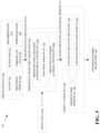
- FIG. 7 is an example 700 of determining a strategic speed plan according to implementations of this invention.
- the example 700 illustrates examples of inputs that can be used by the strategic speed plan module 524 of FIG. 5 to determine a strategic speed plan 714.
- the strategic speed plan module 524 can use more, fewer, or other inputs to determine the strategic speed plan.
- speed limits inputs and acceleration limits inputs can be used.
- the speed limits can include at least one of road speed limits 702, curvature speed limits 704, and seamless autonomous mobility (SAM) data 706.
- the acceleration limits can include vehicle acceleration limits 710 and comfort limits 712.
- the speed limits and/or the acceleration limits can include more, fewer, or other inputs.
- the road speed limits 702 can be the road speed limits, such as those posted on speed limit signs (e.g., 20 MPH, 65 MPH, etc.). In an example, the road speed limits 702 can be obtained from an HD map.
- the curvature speed limits 704 can be data relating vehicle speed to a curvature of a turn, such as a turn along the coarse driveline of the AV. Alternatively, the curvature speed limits 704 can only provide road curvature information (e.g., the turning radius of a curve).
- the curvature speed limits 704 can be limits on the lateral acceleration of the AV. As such, the speed plan can include decreased AV speeds, consistent with the curvature speed limits 704, when the AV curves.
- the SAM data 706 can be data gathered (such as in a cloud-based system) from vehicles (autonomous or otherwise).
- the data can enable vehicles (including AVs) to operate safely and smoothly on the road.
- the SAM data 706 can include vibration data collected from vehicles along a portion of a road.
- the vibration data can correlate vibration levels and speeds at different portions of the road.
- the vibration data may indicate, for a certain road location, an unacceptable level of vibration (for example, due to a speed bump at the portion of the road) when a vehicle is traveling above a certain speed. As such, to minimize the impact of the vibration, the AV is to be slowed down (below the certain speed) at the portion of the road.
- the SAM data 706 can be received by the AV from a central sever, such as the operations center 230, the server computing device 234, or some other network device.
- the SAM data 706 can be data accumulated from other vehicles within a certain time period (e.g., 1 minute, 10 minutes, 20 minutes, etc.) of the autonomous vehicle arriving at that location.
- the AV can pull the SAM data 706.
- the SAM data 706 can be pushed to the AV based on the AV reporting its location to a server that provides the SAM data 706.
- the vehicle acceleration limits 710 can be AV acceleration limits that are due to the torque and power of the AV.
- the comfort limits 712 includes human comfort limits regarding acceleration, such as: How fast do the occupants of the AV want to the AV to accelerate?
- the strategic speed plan module 524 of the reference-trajectory generation layer 504 can combine the raw speed limits 708, the vehicle acceleration limits 710, and the comfort limits 712 to provide the strategic speed plan 714, which is a smooth speed plan.
- Inputs other than those described above can also be used to calculate the strategic speed plan 714.
- road mu relates to the road slipperiness, such as due to ice, rain, slope, etc.
- a minimum cruise time can indicate, for example, that a speed must be maintained for the minimum cruise time (e.g., 3 seconds) before the AV can start decelerating (or accelerating). As such, a more natural speed profile can be provided.
- FIG. 8 is a flowchart diagram of a process 800 for determining a drivable area and a discrete-time speed plan in accordance with an implementation of this invention.
- Some or all aspects of the process 800 can be implemented in a vehicle, including the vehicle 100 shown in FIG. 1 and the vehicle 202 shown in FIG. 2 , or in a computing apparatus, including the controller apparatus 232 shown in FIG. 2 .
- some or all aspects of the process 800 can be implemented in a system combining some or all of the features described in this invention.
- the process 800 can be utilized by the object avoidance layer 506 of FIG. 5 .
- the process 800 identifies nearby objects to the AV.
- the nearby objects can be at least some of the external objects maintained by the world model module 402.
- the nearby objects can be all objects maintained by the world model module 402.
- the nearby objects can be a subset of the objects maintained by the world model module 402.
- the nearby objects can be objects within a predetermined distance from the AV, objects within a predicted arrival time of the AV, or objects that meet other criteria for identifying a subset of the objects.
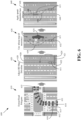
- a static vehicle 920, a static vehicle 914, a dynamic oncoming vehicle 918, and a dynamic vehicle 916 are identified.
- the operation 810 identifies dots (i.e., boundary points) and/or groups of dots representing objects, as described with respect to FIGS. 10-12 .
- the process 800 extracts a drivable area.
- the drivable area can be the area where the AV 912 can be (e.g., legally and/or physically) driven.
- the drivable area can be extracted from the coarse driveline.
- the drivable area can be a predefined distance from the AV along the coarse driveline (e.g., in the longitudinal direction).
- a drivable area 932 in a view 930 of FIG. 9 is an example of the drivable area.
- the drivable area 932 can be the area bounded (i.e., in the lateral direction) by a median 934 and a shoulder 936.
- the drivable area can be extracted from an HD map based on the current location of the AV 912.
- the drivable area can be bounded by the left and right boundaries of a lane (or a road, or some other region) in which the AV 912 is located.
- the drivable area can span the centerline of the road. That is, the opposite-direction traffic lane can be included in the drivable area.
- the drivable area could be a drivable area 938.
- the process 800 adjusts the discrete-time speed plan for static objects. For example, in the absence of obstacles or other road users, the discrete-time speed plan follows the strategic speed profile. For example, when the adjusted drivable area contains a narrow pass, accounting for static objects, instead of following (i.e., using the speed of) the strategic profile verbatim (i.e., as set in the strategic profile), the process 800 adjusts the discrete-time speed plan to reduce the speed of the AV to a comfortable speed. For example, when the adjusted drivable area, accounting for static objects, contains a static blockage, the process 800 adjusts the discrete-time speed plan such that the AV comes to a stop a prescribed distance before the static blockage.
- the process 800 identifies (e.g., predicts, calculates, generates, receives, or otherwise identifies) a respective path for each of the nearby dynamic objects.
- the predictions of the respective paths (i.e., trajectories) of at least some of the dynamic objects can be maintained in a world model, such as the world model module 402 of FIG. 4 .
- the process 800 can receive (e.g., request, read, or otherwise receive) the respective paths from the world model.
- the process 800 can predict for a dynamic object, and, based on the predicted trajectory of the dynamic object, where the dynamic object will be located at different discrete points in time relative to the locations of the AV at the same discrete points in time. Examples of adjusting the drivable area for dynamic objects are further described below with respect to FIGS. 14-16 . An example of a process for adjusting the drivable area for dynamic objects is described below with respect to FIG. 18 .
- the process 800 adjusts the discrete-time speed plan for dynamic objects.
- the adjusted drivable area accounting for both static and dynamic objects at this point
- the dynamic object is labelled as a longitudinal constraint and the discrete-time speed plan is adjusted such that the AV follows the blocking object at a comfortable speed and distance.
- FIGS. 10-12 are examples 1000, 1100, and 1200 of adjusting a drivable area for static objects in accordance with implementations of this invention.
- the examples 1000, 1100, and 1200 illustrate determining static boundaries for a drivable area. That is, FIGS. 10-12 are examples of adjusting a drivable area for static objects as described with respect to the operation 830 of FIG. 8 . That is, the examples 1000, 1100, and 1200 illustrate determining, along the coarse driveline of an AV, where the AV can be driven with reference to static objects.
- each bin can be defined (i.e., set) based on the boundary points assigned to the bin. For example, as a bin 1024 includes no boundary points, a right boundary 1016 and a left boundary 1010 of the bin 1024 are aligned with the (non-adjusted) drivable area. On the other hand, a left boundary 1012 of a bin 1026 is not aligned with the drivable area because a cutout 1028 is excluded from the drivable area; and a right boundary 1014 of the bin 1026 is not aligned with the drivable area because a cutout 1030 is excluded from the drivable area.
- the computed right and left boundaries are used to determine whether the AV 1002 can continue along the coarse driveline 1004.
- the AV 1002 can be advanced (virtually or computationally, not physically) to the center of each bin to determine whether the width of the bin (given the computer boundaries) is such that the AV 1002 can safely fit through the bin.
- the AV 1002 cannot safely clear the left boundary (i.e., the left calculated boundary) of the bin.
- the trajectory of the AV 1002 is to be altered.
- the trajectory of the AV 1002 may not need to be adjusted, as the AV 1002 may need to be stopped, or the trajectory of the AV 1002 can be altered in other ways.
- FIG. 11 illustrates an example 1100 of determining static boundaries and identifying a blockage that is accounted for when adjusting the discrete-time speed plan in accordance with implementations of this invention.
- a coarse driveline 1103 is the coarse driveline of an AV 1102.
- the default drivable area of the AV 1102 is defined by a left boundary 1104 and a right boundary 1106.
- a left lane boundary 1108 and a right lane boundary 1110 of the lane that includes the AV 1102 are shown.
- the drivable area is limited to the lane (i.e., the lane bounded by the left lane boundary 1108 and the right lane boundary 1110) of the AV 1102. As such, the left and right boundaries of the lane are adjusted for static objects.
- the left boundary 1104 and the right boundary 1106 can define the maximum possible drivable area (i.e., maximum boundaries). However, as it may be preferable to keep the AV 1102 within its lane, the left lane boundary 1108 and the right lane boundary 1110 define the boundaries of the drivable area. In an example, if the AV 1102 cannot be safely driven within its own lane (e.g., between the left lane boundary 1108 and the right lane boundary 1110), then it can be evaluated whether the AV 1102 can be driven outside the lane boundaries but within the maximum boundaries. Extending the drivable area can be referred to as "extended drivable area checking.”
- the right lane boundary 1110 includes a portion 1112.
- the portion 1112 is shown as a dashed line because, as further described below, this portion of the drivable area is to be adjusted.
- the drivable area of the AV 1102 is divided into bins, and boundary points corresponding to static objects are assigned to respective bins, such as bins 1116, 1118.
- bins 1116, 1118 As the boundary points of the bins 1116, 1118 appear to correspond to a large, rectangular object, the object may be classified (for example, by the world model module 402 of FIG. 4 ) as a "truck.”
- Boundaries corresponding to (i.e., defined based on) objects can be referred to as hard boundaries.
- a hard boundary is such that, if the planned trajectory were to cross the hard boundary, a collision with another object may be likely.
- lane and/or road markings can be referred to as soft boundaries and represent lawful or logical boundaries.
- a soft boundary is such that, if the planned trajectory were to cross the soft boundary that is not also a hard boundary, the motion of the AV may be unlawful and/or not socially acceptable, but the AV may be safe. As shown in FIG.
- the left boundary 1104 i.e., the left drivable area boundary
- the left lane boundary 1108 defines the left soft boundary
- the right hard boundary is comprised of the right boundary 1106 (i.e., the right drivable area boundary) and the boundary 1114; the right soft boundary is defined by the right lane boundary 1110 and the boundary 1114.
- the trajectory planner determines a trajectory through a gap 1124, such that the drivable area is extended, at least for the bins 1116 and 1118 across the left lane boundary 1108. For example, if the left lane boundary 1108 is the center of the road, the trajectory planner may determine that there are no oncoming dynamic objects and, therefore, it is safe to cross the lane boundary.
- the boundaries of a bin can be adjusted based on the status of the objects (e.g., groups of boundary points) within the bin. For example, the boundary points within a bin can be tracked over time. If it is determined that the group of boundary points within a bin is moving slightly (i.e., less than a threshold level of movement), then a greater level of clearance can be required. That is, the AV 1102 can be driven further away from the boundary points if the boundary points are moving. On the other hand, if the boundary points are stable (i.e., not moving), then the AV 1102 can be driven closer to the boundary points. As such, a boundary of the bin (e.g., the boundary 1114) can be adjusted over time depending on the level of movement of the boundary points within the bin.
- the boundary points within a bin can be tracked over time. If it is determined that the group of boundary points within a bin is moving slightly (i.e., less than a threshold level of movement), then a greater level of clearance can be required. That is, the
- the boundary points are considered to be moving thereafter (i.e., at later times t+x), whether the boundary points continue to move or not.
- Adjusting the bin boundary over time, based on the movement of boundary points within the bin can be referred to as filtered lateral limits.
- "Filtered” in this context means that the lateral limits (e.g., the bin boundaries) can be changed over time.
- Whether a boundary of a cut out area extends to the boundary of the default drivable area can depend on the distance between the cut out area and the boundary of the default drivable area. For example, if a distance corresponding to the gap 1216 between the right edge of the cutout 1210 and the right lane boundary 1206 is below a threshold distance, then the cutout 1210 can be defined by the area extending from a left boundary 1217 of the cutout 1210 to the right lane boundary 1206.
- the threshold distance can relate to a width of the AV 1202.
- the threshold distance can be 1.5, 2.0, etc., times the width of the AV 1202.
- a gap (e.g., a gap 1207) between a cluster (e.g., a cluster 1209) of boundary points of a bin and lane boundary (e.g., the right lane boundary 1206) is also determined.
- the gap 1207 since the gap 1207 is determined to be smaller than the threshold distance (such that the AV 1202 cannot pass through the gap), the cutout 1208 is extended to the right lane boundary 1206.
- the trajectory planner of the AV 1202 may determine that a distance 1212 is such that the AV 1202 can pass through the gap corresponding to the distance 1212. As the cutout 1210 overlaps the coarse driveline 1203, the trajectory planner of the AV 1202 performs a detailed check to determine (e.g., find) a gap to the left or to the right of the cutout 1210 such that the AV 1202 can pass through the gap. If a gap is not found as a result of the detailed check, then the AV 1202 can be considered blocked and must be stopped.
- multi-hypothesis tracking refers to determining a second path (e.g., trajectory) with respect to the second object.
- the process 1300 checks the boundaries of the bins against the coarse driveline.
- the boundaries of the bins are checked against the coarse driveline to determine whether gaps exist such that the AV can pass through at least one of the gaps.
- the operation 1320 can be performed by operations 1320_2-1320_12.
- the operation 1320 adjusts the right and left boundaries of the bins of the drivable area based on the binned boundary points, such as described, for example, with respect to the left boundary 1012 and the right boundary 1014 of the bin 1026 of FIG. 10 .
- the process 1300 identifies the passable gaps. That is the process 1300 identifies the number of passable gaps. For example, given the right and left boundaries of the bin 1116 of FIG. 11 , the process 1300 determines whether the AV 1102 can pass though the gap defined by the distance 1120. If so, then one gap is identified. Similarly, the process 1300 determines whether the AV 1202 can pass through the gap defined by the distance 1212 of FIG. 12 .
- the process 1300 terminates at 1320_12. That is, a trajectory is allowed through the gap. If more than one gap are identified at operation 1320_4, the process 1300 proceeds to operation 1320_8. For example, with respect to the AV 1202 and the cutout 1210, the process 1300 identifies two gaps, namely a gap to the right and a gap to the left of the cutout 1210.
- the process 1300 terminates at the operation 1320_12; otherwise the process 1300 returns to the operation 1320_2 to check for additional obstacles.
- the discrete-time speed plan module 528 computes a respective target speed for longitudinal constraints (i.e., static or dynamic objects that are in the longitudinal direction of the AV) and/or a respective target distance for longitudinal constraints.
- the speed profile uses the current speed of the AV and the distance to the longitudinal constraint to calculate a deceleration speed profile to stop the AV before the longitudinal constraint.
- the module 532 can determine (e.g., predict) the locations of the AV 1402 at different discrete points in time. That is, the module 532 determines locations of arrivals, along the coarse driveline 1403, at different time points. For example, at time t (e.g., in one second), the AV 1402 is predicted to be at a location 1406; at time t+1 (e.g., in two seconds), the AV 1402 is predicted to be at a location 1408; and at time t+2 (e.g., in three seconds), the AV 1402 is predicted to be at a location 1410.
- the time window and frequency can depend on the type (e.g., bicycle, pedestrian, sports car, sedan, large truck, etc.) of the dynamic object.
- the drivable area of the AV 1402 is adjusted to remove those areas that correspond to locations of the vehicle 1404.
- the locations of the AV 1502 at times t, t+1, and t+2 are predicted to be, respectively, locations 1506, 1508, and 1510; and the locations of the vehicle 1504 at time t, t+1, and t+2 are predicted to be, respectively, 1512, 1514, and 1516.
- the trajectory (i.e., the path 1520) of the vehicle 1504 is predicted to overlap the coarse driveline 1503 of the AV 1502. Accordingly, the vehicle 1504 is then classified as a longitudinal constraint.
- an AV 1602 is moving eastward along a coarse driveline 1603, and a vehicle 1604 is moving westward.
- the vehicle 1604 is predicted to follow a path 1609 in order to avoid a parked vehicle 1606.
- the locations of the AV 1602, along the coarse driveline 1603, at times t, t+1, and t+2 are predicted to be, respectively, locations 1610, 1612, and 1614.
- the locations of the vehicle 1604, along the path 1609, at times t, t+1, and t+2 are predicted to be, respectively, 1616, 1618, and 1620.
- the drivable area of the example 1600 is adjusted (i.e., cut out) as described with respect to the cutout 956 of the view 950 of FIG. 9 . That is, the drivable area of the AV 1602 is adjusted to remove those areas that correspond to locations of the vehicle 1604, such as by setting (in this example, left) boundaries of bins corresponding to (i.e., overlapping) the path 1609.
- the trajectory planner can evaluate a width of the drivable area between the point of intersection and the edge of the drivable area. That is, the trajectory planner evaluates a distance 1622 to determine whether a gap defined by the distance 1622 is large enough such that the AV 1602 can pass through. As described above, the distance 1622 is the distance between the calculated boundaries of a bin 1608 that includes the point of intersection.
- the trajectory planner determines the location at which the AV 1602 can clear the vehicle 1604. In an example, for at least some of the predicted locations of the AV 1602, starting from the intersection point (e.g., the location at time t+X, where X is a positive integer number) and going backward in time (e.g., at least some of the locations at times t+X-1, t+X-2, ..., t-1, t), the trajectory planner determines whether, at that location, the AV 1602 can clear the vehicle 1604. In the example 1600, the trajectory planner determines that the AV 1602 can clear the vehicle 1604 at the location 1610.
- the trajectory planner determines whether, at that location, the AV 1602 can clear the vehicle 1604.
- the object avoidance layer 506 processes the objects systematically. If an object is not a constraint, then it can be ignored by the object avoidance layer 506.
- the discrete-time speed plan module 528 can adjust the discrete-time speed profile, as described, for example, with respect to the location 1122 of FIG. 11 .
- the module 532 can adjust the drivable area (or adjusted drivable area), as described, for example, with respect to FIG. 15 .
- the discrete-time speed plan module 528 can adjust the discrete-time speed profile, as described, for example, with respect to FIG. 16 .
- the discrete-time speed plan module 528 can generate a discrete-time speed plan for a future window (e.g., a speed plan for the next 6 seconds) given the constraints.
- the trajectory optimization layer 508 performs an optimization operation(s), such as a constrained operation, to determine an optimal trajectory for the AV based on the constraints.
- the trajectory optimization layer 508 can use (i.e., as inputs to the optimization operation) the motion model (e.g., the kinematic motion model) of the AV, the coarse driveline (e.g., the coarse driveline 1004 of FIG. 10 , the coarse driveline 1103 of FIG. 11 , the coarse driveline 1403 of FIG.
- the optimal trajectory takes into account the coarse driveline and the left and right boundaries, given static and dynamic objects, along the coarse driveline.
- FIG. 17 illustrates additional examples 1700 of trajectory planning in accordance with implementations of this invention.
- one or more trajectory planners such as the trajectory planner 500 of FIG. 5
- a first instance of the trajectory planner determines a trajectory for the autonomous vehicle itself.
- a second trajectory planner instance predicts a trajectory of at least one external dynamic object.
- the first instance can determine a trajectory for the autonomous vehicle itself and can predict the trajectory of the external dynamic object.
- the trajectory planner is used herein to refer to the first instance and/or the second instance.
- a trajectory planner of an AV 1702 predicts that an oncoming vehicle 1704 will follow a trajectory 1706 to avoid a static object 1705.
- the trajectory planner further determines, as described with respect to FIG. 16 , that the AV 1702 cannot pass in a gap between the trajectory of the oncoming vehicle 1704 and a right boundary of the drivable area.
- the trajectory planner determines a speed plan that brings the AV 1702 to a stop at a static blockage 1708 until the oncoming vehicle 1704 is past the static blockage 1708.
- an AV 1720 determines that an oncoming dynamic object 1722 will follow a trajectory 1724.
- the AV 1720 further determines a trajectory 1730 of the AV 1720 such that the AV 1720 is navigated, along a trajectory 1730, to between a first static object 1726 and a second static object 1728, where the AV 1720 is to wait at a static blockage 1732 for a calculated number of seconds and then proceed.
- the calculated number of seconds is the time sufficient for the oncoming dynamic object 1722 to pass the location of the static blockage 1732, such as described with respect to the location 1624 of FIG. 16 .
- a trajectory planner (e.g., a driveline data layer of the trajectory planner) according to this invention can determine (e.g., generate, calculate, select, etc.) a reference (i.e., coarse) driveline.
- the trajectory planner can fuse several input data together to determine the coarse driveline.
- the coarse driveline can be referred to as multi-sourced (i.e., from multiple types of input data).
- the input data can include HD map data, teleoperation data, recorded paths data, preceding vehicle data, parking lot data, and local perception data.
- the trajectory planner can use fewer, more, or other inputs.
- the trajectory planner (e.g., a coarse-driveline concatenation layer of the trajectory planner) can generate (e.g., determine, calculate, etc.) a strategic speed plan that includes specific speed values along the coarse driveline.
- the trajectory planner can use at least one of road curvature, road mu, vehicle speed and/or acceleration limits, minimum cruise times, neighborhood types, as well as more, fewer, or other inputs to generate the strategic speed plan.
- the trajectory planner determines (e.g., calculates) a discrete-time speed plan using, for example, natural acceleration profiles (e.g., a motion model of the AV), lead vehicle acceleration profiles, and determinations of limiting longitudinal constraints.
- the trajectory planner (e.g., an optimized desired trajectory layer of the trajectory planner) generates (e.g., calculates, determines, etc.) an optimized trajectory of the AV using, for example, a constrained optimization operation.
- the optimization operation can be based on, or can include, a quadratic penalty function.
- the optimization operation can be based on, or can include, a logarithmic barrier function.
- the quadratic penalty function can be used with soft constraints.
- the logarithmic barrier function can be used with hard constraints.
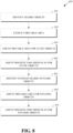
- FIG. 18 is a flowchart diagram of a process 1800 for object avoidance in accordance with the present invention.
- the process 1800 can be executed by a trajectory planner, such as the trajectory planner 500 of FIG. 5 .
- the process 1800 determines, based on the predicted path of the first object, an adjusted drivable area.
- portions can be cut out of the drivable area to generate the adjusted drivable area.
- the adjusted drivable area can be the same as the drivable area.
Landscapes
- Engineering & Computer Science (AREA)
- Transportation (AREA)
- Mechanical Engineering (AREA)
- Automation & Control Theory (AREA)
- Physics & Mathematics (AREA)
- General Physics & Mathematics (AREA)
- Human Computer Interaction (AREA)
- Radar, Positioning & Navigation (AREA)
- Remote Sensing (AREA)
- Chemical & Material Sciences (AREA)
- Combustion & Propulsion (AREA)
- Mathematical Physics (AREA)
- Theoretical Computer Science (AREA)
- Multimedia (AREA)
- Aviation & Aerospace Engineering (AREA)
- Traffic Control Systems (AREA)
- Control Of Driving Devices And Active Controlling Of Vehicle (AREA)
Claims (14)
- Procédé d'évitement d'objet par un véhicule autonome, ou AV, comprenant :l'identification des objets proches de l'AV ;l'extraction d'une zone carrossable (932, 938) de l'AV ;le découpage, pour obtenir une zone carrossable ajustée initiale, de portions découpées (942, 956, 1028, 1030, 1208, 1210) de la zone carrossable, les portions découpées (1028, 1030) correspondant à des objets proches qui sont classés comme des objets statiques, dans lequel le découpage comprend :la division de la zone carrossable en cases (1024, 1026, 1022, 1116, 1118, 1608), chaque case ayant des limites longitudinales et latérales définies par rapport à la direction longitudinale de déplacement de l'AV ;l'affectation de points limites (1008) correspondant aux objets statiques aux cases respectives sur la base d'un emplacement respectif de chacun des objets statiques déterminés à l'aide de capteurs (126) de l'AV ; etpour chaque case à laquelle est affectée au moins un des points limites (1008), l'ajustement des limites latérales de la case pour exclure une zone occupée par ledit au moins un point limite (1008), définissant ainsi une zone carrossable modifiée à l'intérieur de la case, la zone exclue constituant une portion découpée (1028, 1030) ;l'identification d'un premier objet le long d'une ligne de conduite grossière (1004, 1103, 1203, 1403, 1503, 1603) de la zone carrossable ajustée initiale de l'AV, le premier objet étant un objet proche qui est classé comme un objet dynamique ;la réception d'une trajectoire prévue du premier objet ;la détermination, sur la base de la trajectoire prévue du premier objet, d'une zone carrossable ajustée en :
découpant des portions supplémentaires de la première zone carrossable ajustée sur la base de la trajectoire prévue du premier objet et en utilisant des informations de temporisation concernant les emplacements futurs prévus du premier objet et les emplacements futurs calculés de l'AV pour obtenir la zone carrossable ajustée ; etla détermination d'une trajectoire de l'AV à travers la zone carrossable ajustée. - Procédé selon la revendication 1, dans lequel la détermination, sur la base de la trajectoire prévue du premier objet, de la zone carrossable ajustée comprend :l'affectation du premier objet à une case desdites cases ;la définition d'une limite latérale droite et/ou d'une limite latérale gauche de ladite case sur la base du premier objet affecté à la case ; etla détermination de la zone carrossable ajustée sur la base de ladite case.
- Procédé selon la revendication 2, dans lequel la détermination, sur la base de la trajectoire prévue du premier objet, de la zone carrossable ajustée comprend :la détermination des emplacements d'objet respectifs du premier objet à des intervalles de temps discrets ;la détermination des emplacements d'AV respectifs de l'AV aux intervalles de temps discrets ; etla détermination de la zone carrossable ajustée sur la base des emplacements d'objet respectifs et des emplacements d'AV respectifs.
- Procédé selon la revendication 3,dans lequel le premier objet est déterminé comme étant une contrainte longitudinale en sens inverse ; etdans lequel la détermination de la trajectoire de l'AV à travers la zone carrossable ajustée comprend :l'arrêt de l'AV jusqu'à un second temps après un premier temps où un emplacement d'objet du premier objet rencontre un emplacement d'AV de l'AV ; oule ralentissement de l'AV pour qu'il passe derrière le premier objet.
- Procédé selon la revendication 2, comprenant, en outre :
le classement du premier objet comme une contrainte latérale, une contrainte longitudinale, une contrainte latérale en sens inverse ou une contrainte longitudinale en sens inverse. - Procédé selon la revendication 1, dans lequel la détermination de la trajectoire de l'AV à travers la zone carrossable ajustée comprend :la détermination que le premier objet provoque un blocage statique (1708, 1716, 1732, 1740) tel que l'AV est bloqué par le premier objet ; etl'arrêt de l'AV au niveau du blocage statique.
- Procédé selon la revendication 1, comprenant, en outre :la détection d'un second objet,dans lequel la détermination de la trajectoire de l'AV à travers la zone carrossable ajustée comprend :la détermination que le premier objet est franchissable sur un premier côté ;la détermination que le second objet est franchissable sur un premier côté et un second côté ; etla commande de l'AV pour qu'il franchisse le premier objet sur le premier côté et pour qu'il franchisse le second objet sur le premier côté.
- Système d'évitement d'objet par un véhicule autonome, ou AV, comprenant :
un planificateur de trajectoire configuré pour :identifier des objets proches de l'AV ;extraire une zone carrossable de l'AV ;découper, pour obtenir une zone carrossable ajustée initiale, des portions découpées de la zone carrossable, les portions découpées correspondant à des objets proches qui sont classés comme des objets statiques, dans lequel le découpage comprend :la division de la zone carrossable en cases (1024, 1026, 1022, 1116, 1118, 1608), chaque case ayant des limites longitudinales et latérales définies par rapport à la direction longitudinale de déplacement de l'AV ;l'affectation de points limites (1008) correspondant aux objets statiques aux cases respectives sur la base d'un emplacement respectif de chacun des objets statiques déterminés à l'aide de capteurs (126) de l'AV ; etpour chaque case à laquelle est affecté au moins un des points limites (1008), l'ajustement des limites latérales de la case pour exclure une zone occupée par ledit au moins un point limite (1008), définissant ainsi une zone carrossable modifiée à l'intérieur de la case, la zone exclue constituant une portion découpée (1028, 1030) ;identifier un premier objet le long d'une ligne de conduite grossière de la zone carrossable ajustée initiale de l'AV, le premier objet étant un objet proche qui est classé comme un objet dynamique ;recevoir une trajectoire prévue du premier objet ;déterminer, sur la base de la trajectoire prévue du premier objet, une zone carrossable ajustée en :
découpant des portions supplémentaires de la zone carrossable ajustée initiale en utilisant des informations temporelles concernant les emplacements futurs prévus du premier objet et les emplacements futurs calculés d'AV ; etdéterminer une trajectoire de l'AV à travers la zone carrossable ajustée. - Système selon la revendication 8, dans lequel la détermination, sur la base de la trajectoire prévue du premier objet, de la zone carrossable ajustée comprend :l'affectation du premier objet à un case desdites cases ;la définition d'une limite latérale droite et/ou d'une limite latérale gauche de ladite case sur la base du premier objet affecté à la case ; etla détermination de la zone carrossable ajustée sur la base de ladite case.
- Système selon la revendication 9, dans lequel la détermination, sur la base de la trajectoire prévue du premier objet, de la zone carrossable ajustée comprend :la détermination des emplacements d'objet respectifs du premier objet à des intervalles de temps discrets ;la détermination des emplacements d'AV respectifs de l'AV aux intervalles de temps discrets ; etla détermination de la zone carrossable ajustée sur la base des emplacements d'objet respectifs et des emplacements d'AV respectifs.
- Système selon la revendication 10,dans lequel le premier objet est déterminé comme étant une contrainte longitudinale en sens inverse ; etdans lequel la détermination de la trajectoire de l'AV à travers la zone carrossable ajustée comprend :l'arrêt de l'AV jusqu'à un second temps après un premier temps où un emplacement d'objet du premier objet rencontre un emplacement d'AV de l'AV ; ou ; oule ralentissement de l'AV pour qu'il passe derrière le premier objet.
- Système selon la revendication 9, dans lequel le planificateur de trajectoire est en outre configuré pour :
classer le premier objet comme une contrainte latérale, une contrainte longitudinale, une contrainte latérale en sens inverse ou une contrainte longitudinale en sens inverse. - Système selon la revendication 8, dans lequel la détermination de la trajectoire de l'AV à travers la zone carrossable ajustée comprend :la détermination que le premier objet constitue un blocage statique (1708, 1716, 1732, 1740) pour l'AV tel que l'AV est bloqué par le premier objet ; etl'arrêt de l'AV.
- Système selon la revendication 8, dans lequel le planificateur de trajectoire est en outre configuré pour :détecter un second objet,dans lequel la détermination de la trajectoire de l'AV à travers la zone carrossable ajustée comprend :la détermination que le premier objet est franchissable sur un premier côté ;la détermination que le second objet est franchissable sur le premier côté et un second côté ; etcommander l'AV pour qu'il franchisse le premier objet sur le premier côté et pour qu'il franchisse le second objet sur le premier côté.
Applications Claiming Priority (1)
| Application Number | Priority Date | Filing Date | Title |
|---|---|---|---|
| PCT/US2018/035441 WO2019231455A1 (fr) | 2018-05-31 | 2018-05-31 | Planification de trajectoire |
Publications (3)
| Publication Number | Publication Date |
|---|---|
| EP3802254A1 EP3802254A1 (fr) | 2021-04-14 |
| EP3802254A4 EP3802254A4 (fr) | 2022-01-19 |
| EP3802254B1 true EP3802254B1 (fr) | 2024-07-10 |
Family
ID=68697323
Family Applications (1)
| Application Number | Title | Priority Date | Filing Date |
|---|---|---|---|
| EP18921078.4A Active EP3802254B1 (fr) | 2018-05-31 | 2018-05-31 | Planification de trajectoire |
Country Status (6)
| Country | Link |
|---|---|
| US (1) | US12043284B2 (fr) |
| EP (1) | EP3802254B1 (fr) |
| JP (1) | JP7194755B2 (fr) |
| CN (1) | CN112203918B (fr) |
| RU (1) | RU2751382C1 (fr) |
| WO (1) | WO2019231455A1 (fr) |
Families Citing this family (70)
| Publication number | Priority date | Publication date | Assignee | Title |
|---|---|---|---|---|
| JP7103000B2 (ja) * | 2018-07-12 | 2022-07-20 | 株式会社デンソー | 車両制御装置 |
| US11392127B2 (en) * | 2018-10-15 | 2022-07-19 | Zoox, Inc. | Trajectory initialization |
| DE102018217840B4 (de) * | 2018-10-18 | 2025-07-10 | Volkswagen Aktiengesellschaft | Verfahren und System zum Bestimmen eines Umfeldmodells für ein Fahrzeug |
| KR102668309B1 (ko) * | 2018-12-18 | 2024-05-29 | 현대자동차주식회사 | 자율 주행 차량 및 그를 이용한 차량의 주행 제어 방법 |
| CN109712421B (zh) * | 2019-02-22 | 2021-06-04 | 百度在线网络技术(北京)有限公司 | 自动驾驶车辆的速度规划方法、装置和存储介质 |
| FR3093305B1 (fr) * | 2019-02-28 | 2021-01-29 | Psa Automobiles Sa | Régulation de la vitesse d’un véhicule lors d’un dépassement en virage |
| JP2020164045A (ja) * | 2019-03-29 | 2020-10-08 | マツダ株式会社 | 車両走行制御装置 |
| US11731615B2 (en) * | 2019-04-28 | 2023-08-22 | Ottopia Technologies Ltd. | System and method for remote operator assisted driving through collision avoidance |
| US11620907B2 (en) * | 2019-04-29 | 2023-04-04 | Qualcomm Incorporated | Method and apparatus for vehicle maneuver planning and messaging |
| US11772638B2 (en) | 2019-05-07 | 2023-10-03 | Motional Ad Llc | Systems and methods for planning and updating a vehicle's trajectory |
| KR102061750B1 (ko) * | 2019-05-15 | 2020-01-03 | 주식회사 라이드플럭스 | 사전 정보를 이용하여 차량의 주행을 제어하는 방법 및 장치 |
| DE102020206659B4 (de) * | 2019-05-30 | 2026-04-02 | Robert Bosch Gesellschaft mit beschränkter Haftung | Multi-hypothesen-objektverfolgung für automatisierte fahrsysteme |
| JP7325251B2 (ja) * | 2019-07-10 | 2023-08-14 | 日立Astemo株式会社 | 電子制御装置 |
| CN114834443B (zh) * | 2019-09-16 | 2025-11-11 | 深圳引望智能技术有限公司 | 车辆控制的方法、装置、控制器和智能汽车 |
| CN110619666B (zh) * | 2019-09-20 | 2022-05-27 | 阿波罗智能技术(北京)有限公司 | 用于标定相机的方法及装置 |
| JP7215391B2 (ja) | 2019-10-15 | 2023-01-31 | トヨタ自動車株式会社 | 自動運転車両の車両制御システム及び車両制御装置 |
| CN112988923B (zh) * | 2019-12-16 | 2026-02-13 | 阿里巴巴集团控股有限公司 | 一种轨迹生成方法、设备及存储介质 |
| US20210191387A1 (en) * | 2019-12-23 | 2021-06-24 | Autonomous Solutions, Inc. | System and method for assisted teleoperations of vehicles |
| CN111123933B (zh) * | 2019-12-24 | 2021-10-01 | 华为技术有限公司 | 车辆轨迹规划的方法、装置、智能驾驶域控制器和智能车 |
| WO2021134742A1 (fr) * | 2020-01-02 | 2021-07-08 | 华为技术有限公司 | Procédé et dispositif de traitement de trajectoire de déplacement prédite, et procédé et dispositif d'affichage de barrière de restriction |
| US11511760B2 (en) * | 2020-01-23 | 2022-11-29 | Baidu Usa Llc | Cross-platform control profiling tool for autonomous vehicle control |
| WO2021152050A1 (fr) | 2020-01-28 | 2021-08-05 | Five AI Limited | Programmation de robots mobiles |
| US12547175B2 (en) * | 2020-01-28 | 2026-02-10 | Five AI Limited | Planning in mobile robots |
| CN111252069B (zh) * | 2020-02-05 | 2021-08-31 | 北京百度网讯科技有限公司 | 车辆变道的方法及装置 |
| CN113247016A (zh) * | 2020-02-07 | 2021-08-13 | 阿里巴巴集团控股有限公司 | 一种数据处理方法、行驶引导方法、装置及相关设备 |
| EP3866074B1 (fr) * | 2020-02-14 | 2022-11-30 | Robert Bosch GmbH | Procédé et dispositif de commande d'un robot |
| GB2592197A (en) * | 2020-02-18 | 2021-08-25 | Daimler Ag | Autonomous vehicle and system thereof |
| WO2021174445A1 (fr) * | 2020-03-04 | 2021-09-10 | 华为技术有限公司 | Procédé et dispositif de prédiction de la sortie d'un véhicule |
| US11520342B2 (en) * | 2020-03-12 | 2022-12-06 | Pony Ai Inc. | System and method for determining realistic trajectories |
| CN111062372B (zh) * | 2020-03-13 | 2020-07-03 | 北京三快在线科技有限公司 | 一种预测障碍物轨迹的方法及装置 |
| US11745763B2 (en) * | 2020-03-19 | 2023-09-05 | Nissan Motor Co., Ltd. | Vehicle travel assistance method and vehicle travel assistance device |
| JP7369077B2 (ja) * | 2020-03-31 | 2023-10-25 | 本田技研工業株式会社 | 車両制御装置、車両制御方法、及びプログラム |
| US11556127B2 (en) * | 2020-04-03 | 2023-01-17 | Baidu Usa Llc | Static obstacle map based perception system |
| CN111452786B (zh) * | 2020-04-14 | 2021-03-19 | 北京理工大学 | 一种无人车辆避障方法及系统 |
| US11904890B2 (en) * | 2020-06-17 | 2024-02-20 | Baidu Usa Llc | Lane change system for lanes with different speed limits |
| US12071160B2 (en) * | 2020-07-20 | 2024-08-27 | Aurora Operations, Inc. | Systems and methods for generating vehicle corridors to improve path planning efficiency |
| US11945472B2 (en) * | 2020-08-28 | 2024-04-02 | Motional Ad Llc | Trajectory planning of vehicles using route information |
| WO2022049842A1 (fr) * | 2020-09-07 | 2022-03-10 | パナソニックIpマネジメント株式会社 | Procédé de traitement d'informations et dispositif de traitement d'informations |
| US12067881B1 (en) * | 2020-09-29 | 2024-08-20 | United Services Automobile Association (Usaa) | Motor vehicle safety systems and methods for protecting bicyclists |
| DE102020126689A1 (de) * | 2020-10-12 | 2022-04-14 | Volocopter Gmbh | Fluggerät sowie Verfahren und rechnergestütztes System zur Steuerung eines Fluggeräts |
| EP4150426B1 (fr) | 2020-10-30 | 2024-09-18 | Five AI Limited | Outils pour tester des performances et/ou entraîner des planificateurs de véhicules autonomes |
| US12189387B2 (en) * | 2020-11-25 | 2025-01-07 | Zoox, Inc. | Object uncertainty models to assist with drivable area determinations |
| US12116007B2 (en) | 2020-12-09 | 2024-10-15 | Waymo Llc | Trajectory limiting for autonomous vehicles |
| US12585847B2 (en) * | 2020-12-23 | 2026-03-24 | Waymo Llc | Simulations for evaluating driving behaviors of autonomous vehicles |
| JP7400754B2 (ja) * | 2021-02-24 | 2023-12-19 | トヨタ自動車株式会社 | 遠隔支援システム及び遠隔支援方法 |
| US11945441B2 (en) | 2021-03-31 | 2024-04-02 | Nissan North America, Inc. | Explainability and interface design for lane-level route planner |
| US12024204B2 (en) | 2021-04-09 | 2024-07-02 | Direct Cursus Technology L.L.C | Method of and system for predicting a maneuver of an object |
| CN113022593B (zh) * | 2021-04-09 | 2022-10-14 | 长沙智能驾驶研究院有限公司 | 障碍物处理方法、装置和行驶设备 |
| US12060083B2 (en) * | 2021-04-23 | 2024-08-13 | Motional Ad Llc | Planning with dynamic state a trajectory of an autonomous vehicle |
| US20220371613A1 (en) * | 2021-05-21 | 2022-11-24 | Zoox, Inc. | Vehicle trajectory determination |
| CN113415274B (zh) * | 2021-07-14 | 2022-07-05 | 重庆长安汽车股份有限公司 | 自动驾驶的跟车轨迹规划系统、方法、车辆及存储介质 |
| US20230029093A1 (en) | 2021-07-20 | 2023-01-26 | Nissan North America, Inc. | Computing Framework for Vehicle Decision Making and Traffic Management |
| US12542054B2 (en) * | 2021-11-19 | 2026-02-03 | Qualcomm Incorporated | Managing vehicle behavior based on predicted behavior of other vehicles |
| US11938929B2 (en) * | 2021-12-15 | 2024-03-26 | Ford Global Technologies, Llc | Obstacle avoidance for vehicle with trailer |
| US20230192075A1 (en) * | 2021-12-22 | 2023-06-22 | Joseph Burtch | Automated driving obstacle avoidance along a path |
| US12469151B2 (en) * | 2022-02-21 | 2025-11-11 | International Business Machines Corporation | Object trail analytics |
| US12403908B2 (en) | 2022-03-14 | 2025-09-02 | Garrett Transportation I Inc. | Non-selfish traffic lights passing advisory systems |
| US12330633B2 (en) * | 2022-05-17 | 2025-06-17 | Ford Global Technologies, Llc | Obstacle avoidance for vehicle |
| CN114964292B (zh) * | 2022-05-30 | 2023-10-20 | 国汽智控(北京)科技有限公司 | 全局路径规划方法、装置、电子设备及存储介质 |
| CN115103161B (zh) * | 2022-06-22 | 2024-08-16 | 重庆紫光华山智安科技有限公司 | 基于视频推进的巡防方法、系统、设备及介质 |
| JP2024006451A (ja) * | 2022-07-01 | 2024-01-17 | 日産自動車株式会社 | 走行制御方法及び走行制御装置 |
| JP7683568B2 (ja) * | 2022-08-31 | 2025-05-27 | トヨタ自動車株式会社 | 車両案内システム |
| US12497041B2 (en) | 2022-10-19 | 2025-12-16 | Garrett Transportation I Inc. | Driver and lead vehicle prediction model |
| JP7770295B2 (ja) * | 2022-12-08 | 2025-11-14 | 三菱電機株式会社 | 走行経路決定装置及び自動運転システム |
| GB2625577B (en) * | 2022-12-21 | 2025-01-15 | Oxa Autonomy Ltd | Generating a trajectory for an autonomous vehicle |
| CN118683519A (zh) * | 2023-03-23 | 2024-09-24 | 华为技术有限公司 | 一种避让控制方法、智能设备及车辆 |
| CN116588136A (zh) * | 2023-04-28 | 2023-08-15 | 重庆赛力斯新能源汽车设计院有限公司 | 一种车辆可行驶区域的生成方法、装置、设备及介质 |
| KR20250001260A (ko) * | 2023-06-28 | 2025-01-06 | 현대자동차주식회사 | 차량 경로 생성 장치 및 그 방법 |
| CN119502895B (zh) * | 2023-08-11 | 2025-10-10 | 广州汽车集团股份有限公司 | 一种车辆轨迹规划方法及其装置、存储介质 |
| CN118254787B (zh) * | 2024-03-08 | 2024-11-15 | 阿维塔科技(重庆)有限公司 | 车辆控制方法、装置、设备及存储介质 |
Family Cites Families (71)
| Publication number | Priority date | Publication date | Assignee | Title |
|---|---|---|---|---|
| US5646843A (en) | 1990-02-05 | 1997-07-08 | Caterpillar Inc. | Apparatus and method for surface based vehicle control system |
| US5684845A (en) | 1996-08-30 | 1997-11-04 | Framatome Technologies, Inc. | Multi-axis spacer grid keying fixture |
| DE19749306A1 (de) * | 1996-12-20 | 1998-06-25 | Mannesmann Vdo Ag | Verfahren und Anordnung zur vorausschauenden Bestimmung eines Fahrkorridors eines Kraftfahrzeuges |
| US6785610B2 (en) | 1999-12-21 | 2004-08-31 | Lockheed Martin Corporation | Spatial avoidance method and apparatus |
| JP2005316759A (ja) | 2004-04-28 | 2005-11-10 | Mitsubishi Heavy Ind Ltd | 移動体の障害物回避方法及び該移動体 |
| EP1879149B1 (fr) | 2006-07-10 | 2016-03-16 | Fondazione Bruno Kessler | Appareil et procédé de suivi d'objets, ou de parties d'objets, dans une séquence d'images |
| JP4929970B2 (ja) * | 2006-10-18 | 2012-05-09 | アイシン・エィ・ダブリュ株式会社 | 運転支援方法、運転支援装置及び運転支援システム |
| US7912596B2 (en) | 2007-05-30 | 2011-03-22 | Honeywell International Inc. | Vehicle trajectory visualization system |
| US8229163B2 (en) | 2007-08-22 | 2012-07-24 | American Gnc Corporation | 4D GIS based virtual reality for moving target prediction |
| US8374388B2 (en) | 2007-12-28 | 2013-02-12 | Rustam Stolkin | Real-time tracking of non-rigid objects in image sequences for which the background may be changing |
| EP2345998B1 (fr) | 2009-12-01 | 2019-11-20 | Honda Research Institute Europe GmbH | Suivi de plusieurs objets avec une adaptation autonome basé sur les connaissances du niveau de modélisation du suivi |
| US8423336B2 (en) | 2009-12-16 | 2013-04-16 | The United States Of America As Represented By The Secretary Of The Navy | Aerodynamic simulation system and method for objects dispensed from an aircraft |
| US8509982B2 (en) | 2010-10-05 | 2013-08-13 | Google Inc. | Zone driving |
| FR2976355B1 (fr) | 2011-06-09 | 2013-06-21 | Jean Luc Desbordes | Dispositif de mesure de vitesse et de position d'un vehicule se deplacant le long d'une voie de guidage, procede et produit programme d'ordinateur correspondant. |
| EP2615598B1 (fr) | 2012-01-11 | 2017-12-06 | Honda Research Institute Europe GmbH | Véhicule avec supports informatiques permettant de surveiller et de prévoir les réactions de participants au trafic |
| RU2479015C1 (ru) * | 2012-01-11 | 2013-04-10 | Федеральное государственное бюджетное образовательное учреждение высшего профессионального образования "Санкт-Петербургский государственный электротехнический университет "ЛЭТИ" им. В.И. Ульянова (Ленина)" | Способ определения траектории движения автономного транспортного средства в динамической среде |
| DE102012215093A1 (de) | 2012-08-24 | 2014-02-27 | Robert Bosch Gmbh | Fahrerassistenzsystem und Verfahren zum Betreiben des Fahrerassistenzsystems |
| JP5527382B2 (ja) | 2012-10-12 | 2014-06-18 | トヨタ自動車株式会社 | 走行支援システム及び制御装置 |
| US8473144B1 (en) | 2012-10-30 | 2013-06-25 | Google Inc. | Controlling vehicle lateral lane positioning |
| JP5835243B2 (ja) | 2013-02-07 | 2015-12-24 | 株式会社デンソー | 物標認識装置 |
| US9280899B2 (en) * | 2013-08-06 | 2016-03-08 | GM Global Technology Operations LLC | Dynamic safety shields for situation assessment and decision making in collision avoidance tasks |
| DE102013013867A1 (de) * | 2013-08-20 | 2015-03-12 | Audi Ag | Kraftfahrzeug und Verfahren zur Steuerung eines Kraftfahrzeugs |
| US9199668B2 (en) | 2013-10-28 | 2015-12-01 | GM Global Technology Operations LLC | Path planning for evasive steering maneuver employing a virtual potential field technique |
| US9656673B2 (en) | 2013-12-04 | 2017-05-23 | Mobileye Vision Technologies Ltd. | Systems and methods for navigating a vehicle to a default lane |
| US9650051B2 (en) | 2013-12-22 | 2017-05-16 | Lytx, Inc. | Autonomous driving comparison and evaluation |
| US9457807B2 (en) * | 2014-06-05 | 2016-10-04 | GM Global Technology Operations LLC | Unified motion planning algorithm for autonomous driving vehicle in obstacle avoidance maneuver |
| US9428187B2 (en) | 2014-06-05 | 2016-08-30 | GM Global Technology Operations LLC | Lane change path planning algorithm for autonomous driving vehicle |
| KR20150144125A (ko) * | 2014-06-16 | 2015-12-24 | 현대모비스 주식회사 | 안전 운전 유도 시스템 및 이의 방법 |
| JP6264457B2 (ja) | 2014-06-25 | 2018-01-24 | 日産自動車株式会社 | 車両制御装置 |
| US9229453B1 (en) * | 2014-08-29 | 2016-01-05 | GM Global Technology Operations LLC | Unified motion planner for autonomous driving vehicle in avoiding the moving obstacle |
| US9963144B2 (en) * | 2014-08-29 | 2018-05-08 | Nissan Motor Co., Ltd. | Travel control device and travel control method |
| EP3001272B1 (fr) | 2014-09-26 | 2017-04-12 | Volvo Car Corporation | Procédé de planification de trajectoire lors de manoeuvres de fléchissement |
| WO2016151950A1 (fr) | 2015-03-20 | 2016-09-29 | 日本電気株式会社 | Système de surveillance, procédé de surveillance et programme de surveillance |
| US9786177B2 (en) | 2015-04-10 | 2017-10-10 | Honda Motor Co., Ltd. | Pedestrian path predictions |
| JP2016206879A (ja) | 2015-04-21 | 2016-12-08 | 本田技研工業株式会社 | パラメータ分類装置並びにパラメータ分類装置を用いた移動体模擬運動生成装置及び移動体運動生成装置 |
| US9868443B2 (en) | 2015-04-27 | 2018-01-16 | GM Global Technology Operations LLC | Reactive path planning for autonomous driving |
| US10234859B2 (en) | 2015-08-20 | 2019-03-19 | Harman International Industries, Incorporated | Systems and methods for driver assistance |
| US9940625B2 (en) | 2015-09-02 | 2018-04-10 | Ford Global Technologies, Llc | Autonomous driving certification generalizer |
| US10126810B2 (en) | 2015-09-29 | 2018-11-13 | Emerson Process Management Power & Water Solutions, Inc. | Method for controlling power generation unit to desired output as specified by load demand signal by using modified control signal |
| EP3357778B1 (fr) | 2015-09-30 | 2022-10-26 | Sony Group Corporation | Dispositif de commande de conduite, procédé de commande de conduite, et programme |
| US10229363B2 (en) | 2015-10-19 | 2019-03-12 | Ford Global Technologies, Llc | Probabilistic inference using weighted-integrals-and-sums-by-hashing for object tracking |
| WO2017079349A1 (fr) | 2015-11-04 | 2017-05-11 | Zoox, Inc. | Système de mise en oeuvre d'un système de sécurité actif dans un véhicule autonome |
| US9958864B2 (en) | 2015-11-04 | 2018-05-01 | Zoox, Inc. | Coordination of dispatching and maintaining fleet of autonomous vehicles |
| US10496766B2 (en) | 2015-11-05 | 2019-12-03 | Zoox, Inc. | Simulation system and methods for autonomous vehicles |
| US9910441B2 (en) | 2015-11-04 | 2018-03-06 | Zoox, Inc. | Adaptive autonomous vehicle planner logic |
| JP6798779B2 (ja) | 2015-11-04 | 2020-12-09 | トヨタ自動車株式会社 | 地図更新判定システム |
| US10152882B2 (en) | 2015-11-30 | 2018-12-11 | Nissan North America, Inc. | Host vehicle operation using remote vehicle intention prediction |
| KR101714273B1 (ko) * | 2015-12-11 | 2017-03-08 | 현대자동차주식회사 | 자율 주행 시스템의 경로 제어 방법 및 그 장치 |
| DE102016212292A1 (de) | 2016-01-28 | 2017-08-03 | Volkswagen Aktiengesellschaft | Verfahren und Vorrichtung zum Bereitstellen einer Plantrajektorie für ein Kraftfahrzeug |
| DE102016203086B4 (de) | 2016-02-26 | 2018-06-28 | Robert Bosch Gmbh | Verfahren und Vorrichtung zur Fahrerassistenz |
| JP6589713B2 (ja) | 2016-03-24 | 2019-10-16 | トヨタ自動車株式会社 | 自動運転車両を用いたタクシーサービスシステム |
| US9857795B2 (en) | 2016-03-24 | 2018-01-02 | Honda Motor Co., Ltd. | System and method for trajectory planning for unexpected pedestrians |
| US20170329332A1 (en) | 2016-05-10 | 2017-11-16 | Uber Technologies, Inc. | Control system to adjust operation of an autonomous vehicle based on a probability of interference by a dynamic object |
| US10331138B2 (en) * | 2016-07-05 | 2019-06-25 | Baidu Usa Llc | Standard scene-based planning control methods for operating autonomous vehicles |
| US10162354B2 (en) | 2016-07-21 | 2018-12-25 | Baidu Usa Llc | Controlling error corrected planning methods for operating autonomous vehicles |
| WO2018039476A1 (fr) | 2016-08-24 | 2018-03-01 | Keyssa Systems, Inc. | Ports de chargement à unités de communication sans contact intégrées |
| US10345815B2 (en) * | 2016-09-14 | 2019-07-09 | Qualcomm Incorporated | Motion planning and intention prediction for autonomous driving in highway scenarios via graphical model-based factorization |
| CN109791409B (zh) | 2016-09-23 | 2022-11-29 | 苹果公司 | 自主车辆的运动控制决策 |
| US10227075B2 (en) | 2016-09-28 | 2019-03-12 | Baidu Usa Llc | System delay estimation method for autonomous vehicle control |
| US10115305B2 (en) | 2016-09-30 | 2018-10-30 | Nissan North America, Inc. | Optimizing autonomous car's driving time and user experience using traffic signal information |
| US10146223B1 (en) | 2016-10-21 | 2018-12-04 | Waymo Llc | Handling sensor occlusions for autonomous vehicles |
| WO2018079069A1 (fr) * | 2016-10-25 | 2018-05-03 | 本田技研工業株式会社 | Dispositif de commande de véhicule |
| JP6547735B2 (ja) | 2016-12-22 | 2019-07-24 | トヨタ自動車株式会社 | 衝突回避支援装置 |
| JP2018136240A (ja) | 2017-02-23 | 2018-08-30 | 三菱電機株式会社 | 推定装置、推定方法、推定装置を備えた追尾装置、および推定方法を備えた追尾方法 |
| JP6799150B2 (ja) * | 2017-05-25 | 2020-12-09 | 本田技研工業株式会社 | 車両制御装置 |
| US10671079B2 (en) | 2017-10-24 | 2020-06-02 | Waymo Llc | Speed-dependent required lateral clearance for autonomous vehicle path planning |
| US10401863B2 (en) * | 2017-11-22 | 2019-09-03 | GM Global Technology Operations LLC | Road corridor |
| US10706563B2 (en) | 2018-05-15 | 2020-07-07 | Qualcomm Incorporated | State and position prediction of observed vehicles using optical tracking of wheel rotation |
| US10754032B2 (en) | 2018-06-21 | 2020-08-25 | Intel Corporation | Perception device |
| US10829114B2 (en) | 2019-02-06 | 2020-11-10 | Ford Global Technologies, Llc | Vehicle target tracking |
| DE112020002166T5 (de) | 2019-04-29 | 2022-01-20 | Nvidia Corporation | Simulation realistischer testdaten aus transformierten sensordaten der realen welt für autonome maschinenanwendungen |
-
2018
- 2018-05-31 EP EP18921078.4A patent/EP3802254B1/fr active Active
- 2018-05-31 JP JP2020566219A patent/JP7194755B2/ja active Active
- 2018-05-31 US US17/049,112 patent/US12043284B2/en active Active
- 2018-05-31 CN CN201880094076.1A patent/CN112203918B/zh active Active
- 2018-05-31 RU RU2020141590A patent/RU2751382C1/ru active
- 2018-05-31 WO PCT/US2018/035441 patent/WO2019231455A1/fr not_active Ceased
Also Published As
| Publication number | Publication date |
|---|---|
| EP3802254A1 (fr) | 2021-04-14 |
| US20210237769A1 (en) | 2021-08-05 |
| CN112203918B (zh) | 2023-11-21 |
| EP3802254A4 (fr) | 2022-01-19 |
| CN112203918A (zh) | 2021-01-08 |
| JP2021526474A (ja) | 2021-10-07 |
| WO2019231455A1 (fr) | 2019-12-05 |
| JP7194755B2 (ja) | 2022-12-22 |
| US12043284B2 (en) | 2024-07-23 |
| RU2751382C1 (ru) | 2021-07-13 |
Similar Documents
| Publication | Publication Date | Title |
|---|---|---|
| EP3802254B1 (fr) | Planification de trajectoire | |
| EP4004770B1 (fr) | Planification de mesures d'urgence et assurance de sécurité | |
| US10569773B2 (en) | Predicting behaviors of oncoming vehicles | |
| US10698407B2 (en) | Trajectory planning | |
| US10745011B2 (en) | Predicting yield behaviors | |
| US10564643B2 (en) | Time-warping for autonomous driving simulation | |
| US12071127B2 (en) | Proactive risk mitigation | |
| US20210035442A1 (en) | Autonomous Vehicles and a Mobility Manager as a Traffic Monitor | |
| US20250002049A1 (en) | Proactive Risk Mitigation with Generalized Virtual Vehicles | |
| US12280808B2 (en) | Road user categorization through monitoring | |
| US12077177B2 (en) | Autonomous vehicle control and map accuracy determination based on predicted and actual trajectories of surrounding objects and vehicles | |
| US12448007B2 (en) | Imitation learning for trajectory planning |
Legal Events
| Date | Code | Title | Description |
|---|---|---|---|
| STAA | Information on the status of an ep patent application or granted ep patent |
Free format text: STATUS: THE INTERNATIONAL PUBLICATION HAS BEEN MADE |
|
| PUAI | Public reference made under article 153(3) epc to a published international application that has entered the european phase |
Free format text: ORIGINAL CODE: 0009012 |
|
| STAA | Information on the status of an ep patent application or granted ep patent |
Free format text: STATUS: REQUEST FOR EXAMINATION WAS MADE |
|
| 17P | Request for examination filed |
Effective date: 20201228 |
|
| AK | Designated contracting states |
Kind code of ref document: A1 Designated state(s): AL AT BE BG CH CY CZ DE DK EE ES FI FR GB GR HR HU IE IS IT LI LT LU LV MC MK MT NL NO PL PT RO RS SE SI SK SM TR |
|
| AX | Request for extension of the european patent |
Extension state: BA ME |
|
| RAP1 | Party data changed (applicant data changed or rights of an application transferred) |
Owner name: NISSAN NORTH AMERICA, INC. |
|
| DAV | Request for validation of the european patent (deleted) | ||
| DAX | Request for extension of the european patent (deleted) | ||
| A4 | Supplementary search report drawn up and despatched |
Effective date: 20211222 |
|
| RIC1 | Information provided on ipc code assigned before grant |
Ipc: B60W 60/00 20200101ALI20211216BHEP Ipc: G08G 1/16 20060101ALI20211216BHEP Ipc: G05D 1/02 20200101ALI20211216BHEP Ipc: G01C 21/34 20060101ALI20211216BHEP Ipc: B60W 30/08 20120101ALI20211216BHEP Ipc: B60W 30/09 20120101AFI20211216BHEP |
|
| STAA | Information on the status of an ep patent application or granted ep patent |
Free format text: STATUS: EXAMINATION IS IN PROGRESS |
|
| 17Q | First examination report despatched |
Effective date: 20230627 |
|
| REG | Reference to a national code |
Ref country code: DE Ipc: G05D0001000000 Ref country code: DE Ref legal event code: R079 Ref document number: 602018071726 Country of ref document: DE Free format text: PREVIOUS MAIN CLASS: B60W0030090000 Ipc: G05D0001000000 |
|
| GRAP | Despatch of communication of intention to grant a patent |
Free format text: ORIGINAL CODE: EPIDOSNIGR1 |
|
| STAA | Information on the status of an ep patent application or granted ep patent |
Free format text: STATUS: GRANT OF PATENT IS INTENDED |
|
| RIC1 | Information provided on ipc code assigned before grant |
Ipc: B60W 60/00 20200101ALI20240306BHEP Ipc: B60W 30/08 20120101ALI20240306BHEP Ipc: G08G 1/16 20060101ALI20240306BHEP Ipc: B60W 30/09 20120101ALI20240306BHEP Ipc: G05D 1/00 20060101AFI20240306BHEP |
|
| INTG | Intention to grant announced |
Effective date: 20240405 |
|
| GRAS | Grant fee paid |
Free format text: ORIGINAL CODE: EPIDOSNIGR3 |
|
| GRAA | (expected) grant |
Free format text: ORIGINAL CODE: 0009210 |
|
| STAA | Information on the status of an ep patent application or granted ep patent |
Free format text: STATUS: THE PATENT HAS BEEN GRANTED |
|
| AK | Designated contracting states |
Kind code of ref document: B1 Designated state(s): AL AT BE BG CH CY CZ DE DK EE ES FI FR GB GR HR HU IE IS IT LI LT LU LV MC MK MT NL NO PL PT RO RS SE SI SK SM TR |
|
| REG | Reference to a national code |
Ref country code: CH Ref legal event code: EP |
|
| P01 | Opt-out of the competence of the unified patent court (upc) registered |
Free format text: CASE NUMBER: APP_36684/2024 Effective date: 20240619 |
|
| REG | Reference to a national code |
Ref country code: DE Ref legal event code: R096 Ref document number: 602018071726 Country of ref document: DE |
|
| REG | Reference to a national code |
Ref country code: LT Ref legal event code: MG9D |
|
| REG | Reference to a national code |
Ref country code: NL Ref legal event code: MP Effective date: 20240710 |
|
| PG25 | Lapsed in a contracting state [announced via postgrant information from national office to epo] |
Ref country code: PT Free format text: LAPSE BECAUSE OF FAILURE TO SUBMIT A TRANSLATION OF THE DESCRIPTION OR TO PAY THE FEE WITHIN THE PRESCRIBED TIME-LIMIT Effective date: 20241111 |
|
| REG | Reference to a national code |
Ref country code: AT Ref legal event code: MK05 Ref document number: 1702597 Country of ref document: AT Kind code of ref document: T Effective date: 20240710 |
|
| PG25 | Lapsed in a contracting state [announced via postgrant information from national office to epo] |
Ref country code: NL Free format text: LAPSE BECAUSE OF FAILURE TO SUBMIT A TRANSLATION OF THE DESCRIPTION OR TO PAY THE FEE WITHIN THE PRESCRIBED TIME-LIMIT Effective date: 20240710 |
|
| PG25 | Lapsed in a contracting state [announced via postgrant information from national office to epo] |
Ref country code: PT Free format text: LAPSE BECAUSE OF FAILURE TO SUBMIT A TRANSLATION OF THE DESCRIPTION OR TO PAY THE FEE WITHIN THE PRESCRIBED TIME-LIMIT Effective date: 20241111 Ref country code: NL Free format text: LAPSE BECAUSE OF FAILURE TO SUBMIT A TRANSLATION OF THE DESCRIPTION OR TO PAY THE FEE WITHIN THE PRESCRIBED TIME-LIMIT Effective date: 20240710 |
|
| PG25 | Lapsed in a contracting state [announced via postgrant information from national office to epo] |
Ref country code: NO Free format text: LAPSE BECAUSE OF FAILURE TO SUBMIT A TRANSLATION OF THE DESCRIPTION OR TO PAY THE FEE WITHIN THE PRESCRIBED TIME-LIMIT Effective date: 20241010 |
|
| PG25 | Lapsed in a contracting state [announced via postgrant information from national office to epo] |
Ref country code: GR Free format text: LAPSE BECAUSE OF FAILURE TO SUBMIT A TRANSLATION OF THE DESCRIPTION OR TO PAY THE FEE WITHIN THE PRESCRIBED TIME-LIMIT Effective date: 20241011 Ref country code: PL Free format text: LAPSE BECAUSE OF FAILURE TO SUBMIT A TRANSLATION OF THE DESCRIPTION OR TO PAY THE FEE WITHIN THE PRESCRIBED TIME-LIMIT Effective date: 20240710 Ref country code: FI Free format text: LAPSE BECAUSE OF FAILURE TO SUBMIT A TRANSLATION OF THE DESCRIPTION OR TO PAY THE FEE WITHIN THE PRESCRIBED TIME-LIMIT Effective date: 20240710 |
|
| PG25 | Lapsed in a contracting state [announced via postgrant information from national office to epo] |
Ref country code: BG Free format text: LAPSE BECAUSE OF FAILURE TO SUBMIT A TRANSLATION OF THE DESCRIPTION OR TO PAY THE FEE WITHIN THE PRESCRIBED TIME-LIMIT Effective date: 20240710 |
|
| PG25 | Lapsed in a contracting state [announced via postgrant information from national office to epo] |
Ref country code: LV Free format text: LAPSE BECAUSE OF FAILURE TO SUBMIT A TRANSLATION OF THE DESCRIPTION OR TO PAY THE FEE WITHIN THE PRESCRIBED TIME-LIMIT Effective date: 20240710 |
|
| PG25 | Lapsed in a contracting state [announced via postgrant information from national office to epo] |
Ref country code: IS Free format text: LAPSE BECAUSE OF FAILURE TO SUBMIT A TRANSLATION OF THE DESCRIPTION OR TO PAY THE FEE WITHIN THE PRESCRIBED TIME-LIMIT Effective date: 20241110 Ref country code: AT Free format text: LAPSE BECAUSE OF FAILURE TO SUBMIT A TRANSLATION OF THE DESCRIPTION OR TO PAY THE FEE WITHIN THE PRESCRIBED TIME-LIMIT Effective date: 20240710 |
|
| PG25 | Lapsed in a contracting state [announced via postgrant information from national office to epo] |
Ref country code: HR Free format text: LAPSE BECAUSE OF FAILURE TO SUBMIT A TRANSLATION OF THE DESCRIPTION OR TO PAY THE FEE WITHIN THE PRESCRIBED TIME-LIMIT Effective date: 20240710 |
|
| PG25 | Lapsed in a contracting state [announced via postgrant information from national office to epo] |
Ref country code: ES Free format text: LAPSE BECAUSE OF FAILURE TO SUBMIT A TRANSLATION OF THE DESCRIPTION OR TO PAY THE FEE WITHIN THE PRESCRIBED TIME-LIMIT Effective date: 20240710 Ref country code: RS Free format text: LAPSE BECAUSE OF FAILURE TO SUBMIT A TRANSLATION OF THE DESCRIPTION OR TO PAY THE FEE WITHIN THE PRESCRIBED TIME-LIMIT Effective date: 20241010 |
|
| PG25 | Lapsed in a contracting state [announced via postgrant information from national office to epo] |
Ref country code: RS Free format text: LAPSE BECAUSE OF FAILURE TO SUBMIT A TRANSLATION OF THE DESCRIPTION OR TO PAY THE FEE WITHIN THE PRESCRIBED TIME-LIMIT Effective date: 20241010 Ref country code: PL Free format text: LAPSE BECAUSE OF FAILURE TO SUBMIT A TRANSLATION OF THE DESCRIPTION OR TO PAY THE FEE WITHIN THE PRESCRIBED TIME-LIMIT Effective date: 20240710 Ref country code: NO Free format text: LAPSE BECAUSE OF FAILURE TO SUBMIT A TRANSLATION OF THE DESCRIPTION OR TO PAY THE FEE WITHIN THE PRESCRIBED TIME-LIMIT Effective date: 20241010 Ref country code: LV Free format text: LAPSE BECAUSE OF FAILURE TO SUBMIT A TRANSLATION OF THE DESCRIPTION OR TO PAY THE FEE WITHIN THE PRESCRIBED TIME-LIMIT Effective date: 20240710 Ref country code: IS Free format text: LAPSE BECAUSE OF FAILURE TO SUBMIT A TRANSLATION OF THE DESCRIPTION OR TO PAY THE FEE WITHIN THE PRESCRIBED TIME-LIMIT Effective date: 20241110 Ref country code: HR Free format text: LAPSE BECAUSE OF FAILURE TO SUBMIT A TRANSLATION OF THE DESCRIPTION OR TO PAY THE FEE WITHIN THE PRESCRIBED TIME-LIMIT Effective date: 20240710 Ref country code: GR Free format text: LAPSE BECAUSE OF FAILURE TO SUBMIT A TRANSLATION OF THE DESCRIPTION OR TO PAY THE FEE WITHIN THE PRESCRIBED TIME-LIMIT Effective date: 20241011 Ref country code: FI Free format text: LAPSE BECAUSE OF FAILURE TO SUBMIT A TRANSLATION OF THE DESCRIPTION OR TO PAY THE FEE WITHIN THE PRESCRIBED TIME-LIMIT Effective date: 20240710 Ref country code: ES Free format text: LAPSE BECAUSE OF FAILURE TO SUBMIT A TRANSLATION OF THE DESCRIPTION OR TO PAY THE FEE WITHIN THE PRESCRIBED TIME-LIMIT Effective date: 20240710 Ref country code: BG Free format text: LAPSE BECAUSE OF FAILURE TO SUBMIT A TRANSLATION OF THE DESCRIPTION OR TO PAY THE FEE WITHIN THE PRESCRIBED TIME-LIMIT Effective date: 20240710 Ref country code: AT Free format text: LAPSE BECAUSE OF FAILURE TO SUBMIT A TRANSLATION OF THE DESCRIPTION OR TO PAY THE FEE WITHIN THE PRESCRIBED TIME-LIMIT Effective date: 20240710 |
|
| REG | Reference to a national code |
Ref country code: DE Ref legal event code: R097 Ref document number: 602018071726 Country of ref document: DE |
|
| PG25 | Lapsed in a contracting state [announced via postgrant information from national office to epo] |
Ref country code: DK Free format text: LAPSE BECAUSE OF FAILURE TO SUBMIT A TRANSLATION OF THE DESCRIPTION OR TO PAY THE FEE WITHIN THE PRESCRIBED TIME-LIMIT Effective date: 20240710 Ref country code: RO Free format text: LAPSE BECAUSE OF FAILURE TO SUBMIT A TRANSLATION OF THE DESCRIPTION OR TO PAY THE FEE WITHIN THE PRESCRIBED TIME-LIMIT Effective date: 20240710 Ref country code: SM Free format text: LAPSE BECAUSE OF FAILURE TO SUBMIT A TRANSLATION OF THE DESCRIPTION OR TO PAY THE FEE WITHIN THE PRESCRIBED TIME-LIMIT Effective date: 20240710 |
|
| PG25 | Lapsed in a contracting state [announced via postgrant information from national office to epo] |
Ref country code: EE Free format text: LAPSE BECAUSE OF FAILURE TO SUBMIT A TRANSLATION OF THE DESCRIPTION OR TO PAY THE FEE WITHIN THE PRESCRIBED TIME-LIMIT Effective date: 20240710 |
|
| PG25 | Lapsed in a contracting state [announced via postgrant information from national office to epo] |
Ref country code: CZ Free format text: LAPSE BECAUSE OF FAILURE TO SUBMIT A TRANSLATION OF THE DESCRIPTION OR TO PAY THE FEE WITHIN THE PRESCRIBED TIME-LIMIT Effective date: 20240710 |
|
| PG25 | Lapsed in a contracting state [announced via postgrant information from national office to epo] |
Ref country code: IT Free format text: LAPSE BECAUSE OF FAILURE TO SUBMIT A TRANSLATION OF THE DESCRIPTION OR TO PAY THE FEE WITHIN THE PRESCRIBED TIME-LIMIT Effective date: 20240710 Ref country code: SK Free format text: LAPSE BECAUSE OF FAILURE TO SUBMIT A TRANSLATION OF THE DESCRIPTION OR TO PAY THE FEE WITHIN THE PRESCRIBED TIME-LIMIT Effective date: 20240710 |
|
| PLBE | No opposition filed within time limit |
Free format text: ORIGINAL CODE: 0009261 |
|
| STAA | Information on the status of an ep patent application or granted ep patent |
Free format text: STATUS: NO OPPOSITION FILED WITHIN TIME LIMIT |
|
| REG | Reference to a national code |
Ref country code: DE Ref legal event code: R081 Ref document number: 602018071726 Country of ref document: DE Owner name: NISSAN MOTOR CO., LTD., YOKOHAMA-SHI, JP Free format text: FORMER OWNER: NISSAN NORTH AMERICA, INC., FRANKLIN, TN, US |
|
| 26N | No opposition filed |
Effective date: 20250411 |
|
| PGFP | Annual fee paid to national office [announced via postgrant information from national office to epo] |
Ref country code: DE Payment date: 20250529 Year of fee payment: 8 |
|
| REG | Reference to a national code |
Ref country code: GB Ref legal event code: 732E Free format text: REGISTERED BETWEEN 20250612 AND 20250618 |
|
| PGFP | Annual fee paid to national office [announced via postgrant information from national office to epo] |
Ref country code: FR Payment date: 20250526 Year of fee payment: 8 |
|
| PG25 | Lapsed in a contracting state [announced via postgrant information from national office to epo] |
Ref country code: SE Free format text: LAPSE BECAUSE OF FAILURE TO SUBMIT A TRANSLATION OF THE DESCRIPTION OR TO PAY THE FEE WITHIN THE PRESCRIBED TIME-LIMIT Effective date: 20240710 |
|
| REG | Reference to a national code |
Ref country code: CH Ref legal event code: H13 Free format text: ST27 STATUS EVENT CODE: U-0-0-H10-H13 (AS PROVIDED BY THE NATIONAL OFFICE) Effective date: 20251223 |
|
| PG25 | Lapsed in a contracting state [announced via postgrant information from national office to epo] |
Ref country code: LU Free format text: LAPSE BECAUSE OF NON-PAYMENT OF DUE FEES Effective date: 20250531 |
|
| PG25 | Lapsed in a contracting state [announced via postgrant information from national office to epo] |
Ref country code: CH Free format text: LAPSE BECAUSE OF NON-PAYMENT OF DUE FEES Effective date: 20250531 |
|
| REG | Reference to a national code |
Ref country code: BE Ref legal event code: MM Effective date: 20250531 |
|
| PG25 | Lapsed in a contracting state [announced via postgrant information from national office to epo] |
Ref country code: MC Free format text: LAPSE BECAUSE OF FAILURE TO SUBMIT A TRANSLATION OF THE DESCRIPTION OR TO PAY THE FEE WITHIN THE PRESCRIBED TIME-LIMIT Effective date: 20240710 |
|
| PGFP | Annual fee paid to national office [announced via postgrant information from national office to epo] |
Ref country code: GB Payment date: 20260317 Year of fee payment: 9 |
|
| PG25 | Lapsed in a contracting state [announced via postgrant information from national office to epo] |
Ref country code: IE Free format text: LAPSE BECAUSE OF NON-PAYMENT OF DUE FEES Effective date: 20250531 |
|
| PG25 | Lapsed in a contracting state [announced via postgrant information from national office to epo] |
Ref country code: BE Free format text: LAPSE BECAUSE OF NON-PAYMENT OF DUE FEES Effective date: 20250531 |