EP3802385B1 - Dispositif de transport - Google Patents
Dispositif de transport Download PDFInfo
- Publication number
- EP3802385B1 EP3802385B1 EP19730132.8A EP19730132A EP3802385B1 EP 3802385 B1 EP3802385 B1 EP 3802385B1 EP 19730132 A EP19730132 A EP 19730132A EP 3802385 B1 EP3802385 B1 EP 3802385B1
- Authority
- EP
- European Patent Office
- Prior art keywords
- transport
- transport means
- speed
- unit
- tubular pieces
- Prior art date
- Legal status (The legal status is an assumption and is not a legal conclusion. Google has not performed a legal analysis and makes no representation as to the accuracy of the status listed.)
- Active
Links
Images


Classifications
-
- B—PERFORMING OPERATIONS; TRANSPORTING
- B65—CONVEYING; PACKING; STORING; HANDLING THIN OR FILAMENTARY MATERIAL
- B65H—HANDLING THIN OR FILAMENTARY MATERIAL, e.g. SHEETS, WEBS, CABLES
- B65H5/00—Feeding articles separated from piles; Feeding articles to machines
- B65H5/02—Feeding articles separated from piles; Feeding articles to machines by belts or chains, e.g. between belts or chains
- B65H5/021—Feeding articles separated from piles; Feeding articles to machines by belts or chains, e.g. between belts or chains by belts
- B65H5/023—Feeding articles separated from piles; Feeding articles to machines by belts or chains, e.g. between belts or chains by belts between a pair of belts forming a transport nip
-
- B—PERFORMING OPERATIONS; TRANSPORTING
- B31—MAKING ARTICLES OF PAPER, CARDBOARD OR MATERIAL WORKED IN A MANNER ANALOGOUS TO PAPER; WORKING PAPER, CARDBOARD OR MATERIAL WORKED IN A MANNER ANALOGOUS TO PAPER
- B31B—MAKING CONTAINERS OF PAPER, CARDBOARD OR MATERIAL WORKED IN A MANNER ANALOGOUS TO PAPER
- B31B70/00—Making flexible containers, e.g. envelopes or bags
- B31B70/02—Feeding or positioning sheets, blanks or webs
- B31B70/04—Feeding sheets or blanks
-
- B—PERFORMING OPERATIONS; TRANSPORTING
- B31—MAKING ARTICLES OF PAPER, CARDBOARD OR MATERIAL WORKED IN A MANNER ANALOGOUS TO PAPER; WORKING PAPER, CARDBOARD OR MATERIAL WORKED IN A MANNER ANALOGOUS TO PAPER
- B31B—MAKING CONTAINERS OF PAPER, CARDBOARD OR MATERIAL WORKED IN A MANNER ANALOGOUS TO PAPER
- B31B2150/00—Flexible containers made from sheets or blanks, e.g. from flattened tubes
- B31B2150/001—Flexible containers made from sheets or blanks, e.g. from flattened tubes with square or cross bottom
- B31B2150/0014—Flexible containers made from sheets or blanks, e.g. from flattened tubes with square or cross bottom having their openings facing transversally to the direction of movement
-
- B—PERFORMING OPERATIONS; TRANSPORTING
- B31—MAKING ARTICLES OF PAPER, CARDBOARD OR MATERIAL WORKED IN A MANNER ANALOGOUS TO PAPER; WORKING PAPER, CARDBOARD OR MATERIAL WORKED IN A MANNER ANALOGOUS TO PAPER
- B31B—MAKING CONTAINERS OF PAPER, CARDBOARD OR MATERIAL WORKED IN A MANNER ANALOGOUS TO PAPER
- B31B2150/00—Flexible containers made from sheets or blanks, e.g. from flattened tubes
- B31B2150/002—Flexible containers made from sheets or blanks, e.g. from flattened tubes by joining superimposed sheets, e.g. with separate bottom sheets
-
- B—PERFORMING OPERATIONS; TRANSPORTING
- B31—MAKING ARTICLES OF PAPER, CARDBOARD OR MATERIAL WORKED IN A MANNER ANALOGOUS TO PAPER; WORKING PAPER, CARDBOARD OR MATERIAL WORKED IN A MANNER ANALOGOUS TO PAPER
- B31B—MAKING CONTAINERS OF PAPER, CARDBOARD OR MATERIAL WORKED IN A MANNER ANALOGOUS TO PAPER
- B31B2150/00—Flexible containers made from sheets or blanks, e.g. from flattened tubes
- B31B2150/003—Flexible containers made from sheets or blanks, e.g. from flattened tubes made from tubular sheets
-
- B—PERFORMING OPERATIONS; TRANSPORTING
- B31—MAKING ARTICLES OF PAPER, CARDBOARD OR MATERIAL WORKED IN A MANNER ANALOGOUS TO PAPER; WORKING PAPER, CARDBOARD OR MATERIAL WORKED IN A MANNER ANALOGOUS TO PAPER
- B31B—MAKING CONTAINERS OF PAPER, CARDBOARD OR MATERIAL WORKED IN A MANNER ANALOGOUS TO PAPER
- B31B2150/00—Flexible containers made from sheets or blanks, e.g. from flattened tubes
- B31B2150/20—Flexible containers made from sheets or blanks, e.g. from flattened tubes the longitudinal axes of the containers being perpendicular to the direction in which the sheets or blanks are fed
-
- B—PERFORMING OPERATIONS; TRANSPORTING
- B31—MAKING ARTICLES OF PAPER, CARDBOARD OR MATERIAL WORKED IN A MANNER ANALOGOUS TO PAPER; WORKING PAPER, CARDBOARD OR MATERIAL WORKED IN A MANNER ANALOGOUS TO PAPER
- B31B—MAKING CONTAINERS OF PAPER, CARDBOARD OR MATERIAL WORKED IN A MANNER ANALOGOUS TO PAPER
- B31B2160/00—Shape of flexible containers
- B31B2160/20—Shape of flexible containers with structural provision for thickness of contents
-
- B—PERFORMING OPERATIONS; TRANSPORTING
- B31—MAKING ARTICLES OF PAPER, CARDBOARD OR MATERIAL WORKED IN A MANNER ANALOGOUS TO PAPER; WORKING PAPER, CARDBOARD OR MATERIAL WORKED IN A MANNER ANALOGOUS TO PAPER
- B31B—MAKING CONTAINERS OF PAPER, CARDBOARD OR MATERIAL WORKED IN A MANNER ANALOGOUS TO PAPER
- B31B50/00—Making rigid or semi-rigid containers, e.g. boxes or cartons
- B31B50/02—Feeding or positioning sheets, blanks or webs
- B31B50/04—Feeding sheets or blanks
- B31B50/06—Feeding sheets or blanks from stacks
- B31B50/066—Feeding sheets or blanks from stacks from above a magazine
-
- B—PERFORMING OPERATIONS; TRANSPORTING
- B65—CONVEYING; PACKING; STORING; HANDLING THIN OR FILAMENTARY MATERIAL
- B65H—HANDLING THIN OR FILAMENTARY MATERIAL, e.g. SHEETS, WEBS, CABLES
- B65H2404/00—Parts for transporting or guiding the handled material
- B65H2404/20—Belts
- B65H2404/26—Particular arrangement of belt, or belts
- B65H2404/261—Arrangement of belts, or belt(s) / roller(s) facing each other for forming a transport nip
-
- B—PERFORMING OPERATIONS; TRANSPORTING
- B65—CONVEYING; PACKING; STORING; HANDLING THIN OR FILAMENTARY MATERIAL
- B65H—HANDLING THIN OR FILAMENTARY MATERIAL, e.g. SHEETS, WEBS, CABLES
- B65H2404/00—Parts for transporting or guiding the handled material
- B65H2404/20—Belts
- B65H2404/28—Other properties of belts
- B65H2404/285—Other properties of belts including readable marks, patterns, e.g. serving for control
-
- B—PERFORMING OPERATIONS; TRANSPORTING
- B65—CONVEYING; PACKING; STORING; HANDLING THIN OR FILAMENTARY MATERIAL
- B65H—HANDLING THIN OR FILAMENTARY MATERIAL, e.g. SHEETS, WEBS, CABLES
- B65H2513/00—Dynamic entities; Timing aspects
- B65H2513/10—Speed
-
- B—PERFORMING OPERATIONS; TRANSPORTING
- B65—CONVEYING; PACKING; STORING; HANDLING THIN OR FILAMENTARY MATERIAL
- B65H—HANDLING THIN OR FILAMENTARY MATERIAL, e.g. SHEETS, WEBS, CABLES
- B65H2701/00—Handled material; Storage means
- B65H2701/10—Handled articles or webs
- B65H2701/19—Specific article or web
- B65H2701/191—Bags, sachets and pouches or the like
Definitions
- the present invention relates to a transport device, a system and a method for transporting hose sections.
- the correct speed of the double-belt conveyor is of particular importance.
- the reason that the correct processing depends on the position of the tube pieces or the exact positioning in the transport system. For example, a valve slip or a label must be inserted or applied to the correct place on the hose running past.
- the upper and lower belts must run synchronously with one another in order to counteract any friction between the belts and thus increased wear.
- WO 00/26862 A1 discloses a transport device and a method according to the preamble of claims 1 and 12.
- the object of the invention is therefore to propose a device or a system for transporting pieces of tubing that can be used flexibly and in a variety of ways and at the same time ensures the simplest and most precise operation possible.
- a transport device for transporting hose sections which has at least one upper and one lower transport means for guiding the hose sections, upper and lower pressure exertion units for exerting contact pressure on the transport means, and at least one upper and one lower drive unit for driving the transport means.
- the drive takes place at a substantially constant speed in a transport direction (z), with the transport means being arranged at least partially between the upper and lower pressure application units.
- the drive units can be controlled electrically and are arranged within the device in such a way that speed differences between the transport means can be automatically compensated for.
- a significant advantage of the invention is that a speed difference between the means of transport that inevitably arises during a longer process does not have to be adjusted using a lengthy and cumbersome manual process, but can be carried out automatically by selectively controlling electrically controllable drive units. In this way, in particular, the time required to compensate for possible differences in speed can be reduced. This leads to significantly shorter downtimes in production and thus to significant cost advantages.
- the present transport device for transporting tube pieces is used in particular for transporting paper tubes.
- the device in question can also be used to transport plastic hoses, fabric hoses, rubber hoses and the like.
- the transport means are preferably arranged opposite one another and running at least partially parallel to one another. This enables a targeted and controlled alignment of the hoses or pieces of hose to be transported during transport.
- the arrangement of three, four or even more than four means of transport is also conceivable.
- a substantially constant speed is to be understood as meaning a movement that is uniform within certain time segments. However, this does not mean that the speed cannot be changed or varied. Rather, an adjustment of the speed is provided according to the invention.
- speed differences develop between the means of transport in question, especially during longer operating times. These speed differences lead to an asynchronous course of the transport device, which in turn leads to the positioning problems mentioned in the subsequent processing steps. In this case, the speed differences can result, for example, from measurement inaccuracies, uneven wear or uneven loads.
- the compensation according to the invention of speed differences between the two means of transport is to be understood in the present case as a compensation or an adjustment of the speeds of the two means of transport, so that the speed difference is at least reduced, preferably eliminated.
- the compensation of the speed differences of the means of transport should be done objectively by means of an automated control of the electrically controllable drive units.
- electrical control is to be understood more broadly within the scope of the invention, so that electrical control is understood to mean all control options in which the control includes an exchange of electrical signals.
- the transport means for guiding the tube pieces are advantageously designed as belts, in particular as flat belts.
- flat belts promise a particularly simple design and high belt speeds.
- very large forces can be transmitted when using flat belts.
- V-belts, V-ribbed belts, synchronous belts or toothed belts can also be used.
- the upper transport means is at least partially arranged directly on the lower transport means. Arranged directly is to be understood in the sense of directly adjacent or contacting. Such an arrangement makes it possible, in particular, to exert a higher contact pressure on the workpieces to be transported, so that optimal positioning of the workpieces is ensured.
- the means of transport have indices that can be detected by sensors for determining the speed differences.
- the indices can be formed in particular as shaping indices, for example with protruding and/or recessed areas such as teeth, flags or the like on the transport means.
- the indices that can be detected by sensors can also be formed as electromagnetic indices, for example by incorporating magnets, iron cores or the like.
- imprintable indices that can be detected by sensors are also conceivable for determining the speed differences.
- the pressure-exerting units can be formed as rollers, in particular as resilient rollers.
- Such a design of the pressure application units promises, in particular, a particularly uniform pressure distribution, which is particularly advantageous with regard to preventing any incorrect positioning.
- the pressure application units can comprise magnetic and/or magnetizable elements. These can be incorporated into the at least one upper and one lower means of transport, so that the means of transport attract each other. The pressure distribution can thus be evened out even better.
- the rollers can also be movably mounted and opposite rollers can be attracted by means of magnetic forces, in which magnetic and/or magnetizable elements are applied the roles work. Further elements are conceivable which attract one another, for example on the basis of electrostatic or electromagnetic interaction, in order to exert the required pressure.
- the drive units are preferably designed as electromotive drive units, in particular as electronic direct drives.
- each drive unit is preferably assigned to a means of transport within the scope of effective controllability.
- the speed difference can be compensated for in a particularly simple manner by changing the setpoint speed of a means of transport.
- more than two drive units can also be provided in the device according to the invention.
- the drive units can advantageously be in the form of motors which, in addition to controlling the angular position, also allow the acceleration and rotational speed to be controlled.
- the drive units can be in the form of servomotors.
- servomotors enable high positioning accuracy, high dynamics, high speed accuracy, a large speed range, a compact and lightweight design and a short run-up time.
- the drive units can also be in the form of stepping motors.
- the subject matter of the invention is also a system for transporting hose sections with the features of the independent system claim.
- the present system includes the transport device described above for transporting hose sections, a detection unit for acquiring data to determine a speed difference between the transport means and a processing unit for determining a speed difference between the transport means on the basis of the acquired data. Finally, the present system also has a control unit for compensating for the determined speed difference.
- the detection unit has at least one sensor for acquiring data, by means of which a speed difference between the means of transport can be determined.
- the sensor can, for example, record the current currently being tapped at the means of transport, a current moment of the means of transport or other specific data from which a speed difference between the means of transport can be determined.
- the sensors of the detection unit could determine the data required to determine the speed differences with the aid of indices arranged on the means of transport that can be detected by sensors.
- the indices that can be detected by sensors can be shaping indices, such as protruding and/or recessed areas, electromagnetic indices, such as magnets, iron cores or the like, or also printable indices that can be detected by sensors.
- the detection unit has at least two sensors which are preferably arranged at different positions in the system, in particular at different positions on the device for transporting hose sections.
- the arranged sensors are designed and positioned in such a way that they enable an exact position detection.
- the sensors can preferably be in the form of light barriers or cameras and can be arranged at the entrance and exit of the transport device, so that a speed difference between the transport means can be determined by simply comparing the distance covered with the target speed of the transport means.
- the detection unit determines the difference in speed between the transport means on the basis of position data of the tube pieces to be transported.
- a piece of tubing can be detected, for example, at two positions, so that the speed difference of the means of transport can also be determined here in a simple manner by comparing the distance covered with the target speed of the respective means of transport.
- This can be sensory detectable indices can be arranged, for example, on or in labels that are attached to the tube pieces by means of the transport device in question before the tube pieces are transported. In this way, an arrangement of indices on the means of transport is not necessary, so that the transport device according to the invention or the system according to the invention can also be easily integrated into already existing transport devices or systems.
- the detection unit determines the speed difference between the means of transport on the basis of data from different, in particular a large number of different sensors a processing unit is averaged and/or weighted and/or subjected to other statistical data evaluation methods.
- the system has at least one supply unit for supplying individual tube pieces and/or at least one discharge unit for discharging tube pieces transported within the transport device.
- the system can be provided within the framework of a particularly fail-safe system that additional control and/or alignment units for the control and/or alignment of the transported tube pieces are arranged on the feed and/or discharge unit.
- the system according to the invention also has at least one, preferably a plurality of processing stations, in particular with regard to a process that is as automated as possible for the production of tubular packaging from individual tubular pieces.
- the system in question can have, in particular, a bottom laying unit and/or a valve slip unit and/or a bottom unit and/or a carrying strap unit as processing stations.
- the processing stations can advantageously be arranged uniformly along the transport device, so that the tube pieces can be fed to the individual processing stations one after the other with the aid of the transport means.
- the individual system components can preferably communicate wirelessly on a server or cloud basis and/or via the Internet.
- the system can also be designed as a learning unit and change parameters based on collected data and empirical values and thus adapt the operation.
- the invention also relates to a paper bottom layer, comprising a transport device for transporting tube pieces, in particular comprising a system for transporting tube pieces.
- the present method for transporting tube pieces includes in particular the steps of guiding the tube pieces by means of an upper and a lower means of transport, exerting a contact pressure on the means of transport by means of pressure exertion units arranged above and below the means of transport, driving the means of transport with a substantially constant Speed by means of at least two electrically controllable drive units, the transport means being controlled by the electrically controllable drive units in such a way that speed differences between the two transport means are automatically compensated for.
- the method also includes the acquisition of data for determining a speed difference between the means of transport by means of a detection unit.
- the acquisition of data for determining a speed difference can be carried out in particular using various sensors which are preferably arranged at different positions of the system in question in accordance with the explanations regarding the transport device according to the invention.
- the present method can preferably provide that a speed difference between the means of transport is determined by a processing unit on the basis of the recorded data and/or the determined speed difference is then compensated for by a control unit.
- compensation can take place in particular in that the control unit, depending on the speed difference determined by the processing unit, sends a signal to one of the drive units, which then adjusts the drive speed accordingly.
- the method in addition to compensating for speed differences between the means of transport, particularly when determining the difference in speed between the means of transport on the basis of position data of the means of transport to be transported hose pieces, also includes a correction of the positioning of hose pieces.
- a position of a piece of tubing can be detected by means of a detection unit and compared with a target position.
- a further correction value can then be determined from the deviation, which can be used to correct the positioning of the sacks in relation to the processing tools.
- FIG 1 shows a schematic representation of the production of tubular bags.
- individual hose pieces 6 made from a hose are transported one after the other by means of a transport device 2 and fed to individual processing stations 4 one after the other.
- Various processing steps are then carried out in the individual processing stations 4 in order to form a finished tubular packaging 6 ′ from the tubular pieces 6 .
- the first processing station 4 for example, the end of the hose is pulled open so that the open bottom now lies in one plane.
- a first valve sheet is introduced into the open bottom of the piece of tubing 6.
- another valve sheet is then introduced into the tube piece 6 in question.
- areas of the floor are coated with glue or the like.
- the bases are added and the layers provided with adhesive are glued together.
- a bottom cover sheet is finally applied to the tension-bonded bottom of the now finished tubular packaging 6'.
- the transport device 2 shows a transport device 2 for transporting tube pieces 6 from the prior art.
- the transport device 2 here comprises an upper and a lower transport means 14, 14', on which the separated tube pieces 6 are guided along the transport direction z.
- the tube pieces 6 are held between the transport means 14, 14' by the upper and lower pressure application units 16 and 16' exerting a contact pressure on the transport means 14 and 14'.
- the transport means 14, 14' can preferably be formed as belts, in particular as flat belts.
- the transport means 14, 14' are driven by the drive units 12, 12' at a substantially constant speed.
- the transport means 14, 14' are held in their position via deflection rollers 18 arranged at various points of the transport device 2.
- FIG. 3 shows a transport device 2 according to the invention according to a first embodiment.
- the transport device according to the invention 2 electrically controllable drive units 12 and 12 'on such within the transport device 2 are arranged such that a compensation of speed differences between the two transport means 14, 14' can be automated.
- the drive units 12, 12' are preferably formed as electromotive drive units, in particular as electromotive direct drives, for example as servomotors or the like. If an asynchronous course of the transport means 14 and 14' to one another or a speed difference between the transport means 14 and 14' is registered, the speed differences can be compensated for by changing the setpoint speed of a transport means 14 or 14'. In this way, the disadvantageous, tedious and non-automatable adjustment process known from the prior art is eliminated.
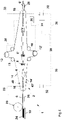
- FIG. 4 shows a system 1 for transporting tube pieces 6 comprising a device for transporting tube pieces 6 according to a second exemplary embodiment.
- the individual tube pieces 6 arranged on a stack 24 are conveyed from a storage unit 22 to a first feed unit 26 via a rotary feeder 20 .
- the tube pieces 6 now reach the transport device 2, in which the tube pieces 6 are guided through the transport device 2 via the transport means 14 and 14' and fed to the individual processing stations 4.
- the finished tubular packaging 6' is fed to the removal device 28.
- the present system also has a detection unit 30.
- the detection unit 30 comprises two sensors 32, which in the simplest case can be in the form of light barriers 33, cameras or the like.
- the sensors 32 are now used to acquire data for determining the speeds of the transport means 14 and 14' with the aid of indices 40, 40' which can be detected by sensors and which are arranged on the transport means 14 and 14'.
- the on the means of transport 14 and 14 'arranged indices 40 and 40' are detected both at the entrance and at the exit of the sensor 32, whereby the speed of the respective means of transport 14, 14 'in a simple manner - for example, via a Comparison of the target speed with the actual speed - can be clearly determined.
- other or even just one sensor 32 can be arranged in the present system 1 for transporting hose sections 6, by means of which data for determining the speed differences of the transport means 14 and 14' can be recorded.
- the measured values recorded by the sensor 32 or the sensors 32 are fed to the processing unit 34, which determines a speed difference between the transport means 14 and 14' from the measured values.
- control unit 36 Depending on the determined speed difference, the speed difference can now be corrected or compensated via control unit 36, in that control unit 36 sends a corresponding signal to one of the drive units, which then corrects the drive speed of at least one means of transport and thus compensates for the speed difference between the means of transport compensated.
- the components arranged within the system 1, in particular the control unit 36, the processing unit 34, the detection unit 30, the sensors 32 and the drive units 12, 12' are connected to one another via a communication and control line 38, so that smooth communication and Control between the devices is guaranteed.
- the individual components of the system 1 in question can also be connected to one another wirelessly via Bluetooth, NFC, WLAN or the like.
Landscapes
- Engineering & Computer Science (AREA)
- Mechanical Engineering (AREA)
- Control Of Conveyors (AREA)
Claims (15)
- Dispositif de transport (2) pour le transport de sections de gaines (6), comprenant au moins des moyens de transport supérieur et inférieur (14, 14') pour le guidage des sections de gaines (6), des unités d'application de pression supérieure et inférieure (16, 16') pour l'application d'une pression sur les moyens de transport (14, 14'), au moins des unités d'entraînement supérieure et inférieure (12, 12') pour l'entraînement des moyens de transport (14, 14') dans une direction de transport (z) avec une vitesse globalement constante, dans lequel les moyens de transport (14, 14') sont disposés au moins partiellement entre les unités d'application de pression supérieure et inférieure (16, 16')
caractérisé en ce que
les unités d'entraînement (12, 12') sont contrôlables électriquement et sont disposées dans le dispositif (2) de façon à ce que les différences de vitesses entre les deux moyens de transport (14, 14') puissent être compensées automatiquement. - Dispositif de transport (2) selon la revendication 1,
caractérisé en ce que
les moyens de transport (14, 14') sont conçus sous la forme de courroies, plus particulièrement de courroies plates. - Dispositif de transport (2) selon la revendication 1 ou 2,
caractérisé en ce que
le moyen de transport supérieur (14) est disposé au moins partiellement directement sur le moyen de transport inférieur (14') et/ou en ce que les moyens de transport (14, 14') comprennent des index (40, 40'), lisibles par des capteurs, pour la détermination des différences de vitesses. - Dispositif de transport (2) selon l'une des revendications précédentes,
caractérisé en ce que
les unités d'application de pression (16, 16') sont conçues sous la forme de rouleaux, plus particulièrement des rouleaux élastiques et/ou en ce que les unités d'entraînement (12, 12') sont conçus sous la forme d'unités d'entraînement à moteurs électriques, plus particulièrement sous la forme d'entraînements directs à moteurs électriques, dans lequel, de préférence, chaque unité d'entraînement (12, 12') correspond à un moyen de transport (14, 14'). - Système (1) pour le transport de sections de gaines (6), comprenant :- un dispositif de transport (2) pour le transport de sections de gaines (6) selon l'une des revendications 1 à 4,- une unité de détection (30) pour la détection de données pour la détermination d'une différence de vitesse entre les moyens de transport (14, 14'),- une unité de traitement (34) pour la détermination d'une différence de vitesse entre les moyens de transport (14, 14') sur la base des données détectées,- une unité de commande (36) pour la compensation de la différence de vitesse déterm inée.
- Système (1) selon la revendication 5,
caractérisé en ce que
l'unité de détection (30) comprend au moins un capteur (32) pour la détection des données, au moyen desquelles une différence de vitesse entre les moyens de transport (14, 14') peut être déterminée. - Système (1) selon la revendication 5 ou 6,
caractérisé en ce que
l'unité de détection (30) comprend au moins deux capteurs (32) qui sont disposés de préférence au niveau de différentes positions du système (1), plus particulièrement au niveau de différentes position du dispositif (2) pour le transport de sections de gaines (6), dans lequel les capteurs (32) permettent, plus particulièrement une détection de position. - Système (1) selon l'une des revendications 5 à 7,
caractérisé en ce que
l'unité de détection (30) détermine la différence de vitesse entre les moyens de transport (14, 14') sur la base des données de position des sections de gaines (6) à transporter et/ou en ce que l'unité de détection (30) détermine la différence de vitesse entre les moyens de transport (14, 14') sur la base des données de différents capteurs (32), qui sont moyennées et/ou pondérées avant une détermination d'une vitesse au moyen d'une unité de traitement (34). - Système (1) selon l'une des revendications 5 à 8,
caractérisé en ce que
le système (1) comprend au moins une unité d'alimentation (26) pour l'alimentation de sections de gaines (6) individuelles et/ou au moins une unité d'évacuation (28) pour l'évacuation des sections de gaines (6) transportées à l'intérieur du dispositif de transport (2). - Système (1) selon l'une des revendications 5 à 9,
caractérisé en ce que
le système (1) comprend au moins une unité de traitement (4), plus particulièrement une unité à poser au sol et/ou une unité de feuille à soupape et/ou une unité au sol et/ou une unité à sangle. - Dispositif de pose de sol en papier comprenant un dispositif de transport (2) pour le transport de sections de gaines (6) selon l'une des revendications 1 à 4, plus particulièrement comprenant un système (1) selon l'une des revendications 4 à 10.
- Procédé pour le transport de sections de gaines (6) comprenant les étapes suivantes :- guidage des sections de gaines (6) au moyen d'un moyen de transport supérieur et d'un moyen de transport inférieur (14, 14'),- application d'une pression sur les moyens de transport (14, 14') au moyen d'unités d'application de pression (16, 16') disposées au-dessus et en dessous des moyens de transport (14, 14'),- entraînement des moyens de transport (14, 14') avec une vitesse globalement constante au moyen d'au moins deux unités d'entraînement électriques (12, 12'),caractérisé en ce que
les moyens de transport (14, 14') sont contrôlés par les unités d'entraînement électriques (12, 12') de façon à ce que les différences de vitesse entre les deux moyens de transport (14, 14') soient compensées automatiquement. - Procédé selon la revendication 12,
caractérisé en ce que
le procédé comprend une détection de données pour la détermination d'une différence de vitesse entre les moyens de transport (14, 14') au moyen d'une unité de détection (30) et/ou en ce que le procédé comprend une détermination d'une différence de vitesse entre les moyens de transport (14, 14') au moyen d'une unité de traitement (34) sur la base des données détectées et/ou une compensation de la différence de vitesse déterminée au moyen d'une unité de commande (36). - Procédé selon l'une des revendications 12 à 13,
caractérisé en ce que
le procédé comprend, en plus d'une compensation des différences de vitesses entre les deux moyens de transport (14, 14'), plus particulièrement lors d'une détermination de la différence de vitesse entre les moyens de transport (14, 14') sur la base des données de position des sections de gaines (6) à transporter, également une correction du positionnement des sections de gaines (6). - Procédé selon la revendication 14,
caractérisé en ce que
une correction supplémentaire du positionnement des sections de gaines (6) a lieu en fonction d'au moins un des paramètres suivants :- valeur de l'écart entre la position réelle et une position de consigne,- nombre total d'étapes de production à exécuter,- étape de production actuelle de la section de gaine (6) concernée dans l'ensemble du processus de production,- standard de qualité exigé,- coût du produit,- taille des lots de production,- vitesse du processus, plus particulièrement vitesse actuelle des moyens de transport (14, 14').
Applications Claiming Priority (2)
| Application Number | Priority Date | Filing Date | Title |
|---|---|---|---|
| DE102018113631.5A DE102018113631A1 (de) | 2018-06-07 | 2018-06-07 | Transportvorrichtung |
| PCT/EP2019/064716 WO2019234124A1 (fr) | 2018-06-07 | 2019-06-05 | Dispositif de transport |
Publications (2)
| Publication Number | Publication Date |
|---|---|
| EP3802385A1 EP3802385A1 (fr) | 2021-04-14 |
| EP3802385B1 true EP3802385B1 (fr) | 2022-03-30 |
Family
ID=66826962
Family Applications (1)
| Application Number | Title | Priority Date | Filing Date |
|---|---|---|---|
| EP19730132.8A Active EP3802385B1 (fr) | 2018-06-07 | 2019-06-05 | Dispositif de transport |
Country Status (4)
| Country | Link |
|---|---|
| EP (1) | EP3802385B1 (fr) |
| DE (1) | DE102018113631A1 (fr) |
| ES (1) | ES2912061T3 (fr) |
| WO (1) | WO2019234124A1 (fr) |
Families Citing this family (1)
| Publication number | Priority date | Publication date | Assignee | Title |
|---|---|---|---|---|
| EP3882012A3 (fr) * | 2020-03-18 | 2022-01-05 | Windmöller & Hölscher KG | Dispositif de fabrication de sacs ou des sacs et procede de fabrication de sacs ou de sacs |
Family Cites Families (4)
| Publication number | Priority date | Publication date | Assignee | Title |
|---|---|---|---|---|
| GB9824162D0 (en) * | 1998-11-04 | 1998-12-30 | Rue De Int Ltd | Sheet transport system |
| DE19853026C1 (de) * | 1998-11-18 | 2000-03-30 | Icoma Fbs Gmbh Packtechnik | Vorrichtung zum Ausrichten von Schlauchabschnitten |
| JP5323631B2 (ja) * | 2009-09-29 | 2013-10-23 | 大日本スクリーン製造株式会社 | インクジェット画像記録装置およびベルト搬送補正方法 |
| DE102009047362B4 (de) * | 2009-11-25 | 2013-07-04 | Windmöller & Hölscher Kg | System und Verfahren zum Herstellen von Säcken oder Beuteln |
-
2018
- 2018-06-07 DE DE102018113631.5A patent/DE102018113631A1/de not_active Withdrawn
-
2019
- 2019-06-05 ES ES19730132T patent/ES2912061T3/es active Active
- 2019-06-05 EP EP19730132.8A patent/EP3802385B1/fr active Active
- 2019-06-05 WO PCT/EP2019/064716 patent/WO2019234124A1/fr not_active Ceased
Also Published As
| Publication number | Publication date |
|---|---|
| WO2019234124A1 (fr) | 2019-12-12 |
| EP3802385A1 (fr) | 2021-04-14 |
| ES2912061T3 (es) | 2022-05-24 |
| DE102018113631A1 (de) | 2019-12-12 |
Similar Documents
| Publication | Publication Date | Title |
|---|---|---|
| DE60212167T2 (de) | Verfahren zur zuführungsregelung eines elastischen materials | |
| DE3543846C2 (fr) | ||
| EP2098469B1 (fr) | Procédé de mesure de la position de feuilles et d'alignement de feuilles | |
| EP2164784A1 (fr) | Alignement de produits alimentaires | |
| EP2697050A1 (fr) | Procédé et dispositif permettant d'orienter une bande de protection | |
| DE102012107215A1 (de) | Vorrichtung zum Überlappspleißen von Cordband | |
| EP1892086B1 (fr) | Réglage de position sur un revêtement de sol doté d'un traitement d'image | |
| EP0085418A2 (fr) | Procédé et installation pour appliquer des étiquettes auto-adhésives | |
| EP3802385B1 (fr) | Dispositif de transport | |
| EP3807200B1 (fr) | Transfert de tuyaux flexibles | |
| EP4342664B1 (fr) | Procédé de fabrication de composants stratifiés individuels en forme de bande comprenant un composant électronique noyé entre deux couches stratifiées et dispositif de fabrication de tels composants stratifiés | |
| EP3495131B1 (fr) | Dispositif et procédé d'enroulement d'une ceinture appropriée à la fabrication d'une bande de structure de ceinture d'une ceinture de pneumatique de véhicule à un tambour de structure de ceinture | |
| DE3900776C2 (de) | Vorrichtung zum Ausrichten der seitlichen Position eines blattförmigen Elements | |
| EP3142952B1 (fr) | Dispositif et procédé pour régler la position d'une bande de matériau d'emballage rélatif à une référence dans une machine d'emballage | |
| EP3814128B1 (fr) | Positionnement d'outil lors du traitement d'éléments tubulaires | |
| EP3814257A1 (fr) | Dispositif de pose de fond et procédé de fabrication d'une pièce tubulaire dotée d'au moins un fond | |
| EP3814256B1 (fr) | Dispositif de pose de fond et procédé permettant la fabrication d'articles tubulaires pourvus au moins d'un fond | |
| DE102006018642A1 (de) | Vorrichtung zum Erfassen von Parametern einer Kante eines Materialstückes und zum Regeln des Versatzes desselben | |
| EP1882659A2 (fr) | Presse de découpage et de cannelage et procédé destiné à l'orientation des feuilles | |
| DE102015010251B4 (de) | Verfahren zur Bearbeitung und Veredelung einer endlosen Warenbahn mit wiederkehrenden unterschiedlichen Formatlängen | |
| EP2392213B1 (fr) | Dispositif d'introduction pour morceaux de pâte brute, notamment pour des tronçons de pâte préformés pour la fabrication de bretzels et procédé d'introduction de morceaux de pâte brute | |
| DE102019110339A1 (de) | Druck- und Etikettiermaschine und Verfahren zum individualisierten Bedrucken von Etiketten | |
| DE102019107467A1 (de) | System und Verfahren zur Bearbeitung von Schlauchstücken | |
| EP4560752A1 (fr) | Procédé et dispositifs de fabrication de monocellules et de piles de cellules formées à partir de celles-ci pour batteries | |
| WO2025008485A1 (fr) | Appareil et procédé pour fournir des éléments adhésifs de préférence plats |
Legal Events
| Date | Code | Title | Description |
|---|---|---|---|
| STAA | Information on the status of an ep patent application or granted ep patent |
Free format text: STATUS: UNKNOWN |
|
| STAA | Information on the status of an ep patent application or granted ep patent |
Free format text: STATUS: THE INTERNATIONAL PUBLICATION HAS BEEN MADE |
|
| PUAI | Public reference made under article 153(3) epc to a published international application that has entered the european phase |
Free format text: ORIGINAL CODE: 0009012 |
|
| STAA | Information on the status of an ep patent application or granted ep patent |
Free format text: STATUS: REQUEST FOR EXAMINATION WAS MADE |
|
| 17P | Request for examination filed |
Effective date: 20210111 |
|
| AK | Designated contracting states |
Kind code of ref document: A1 Designated state(s): AL AT BE BG CH CY CZ DE DK EE ES FI FR GB GR HR HU IE IS IT LI LT LU LV MC MK MT NL NO PL PT RO RS SE SI SK SM TR |
|
| AX | Request for extension of the european patent |
Extension state: BA ME |
|
| DAV | Request for validation of the european patent (deleted) | ||
| DAX | Request for extension of the european patent (deleted) | ||
| GRAP | Despatch of communication of intention to grant a patent |
Free format text: ORIGINAL CODE: EPIDOSNIGR1 |
|
| RIC1 | Information provided on ipc code assigned before grant |
Ipc: B31B 70/04 20170101ALI20211029BHEP Ipc: B31B 70/00 20170101ALI20211029BHEP Ipc: B65H 5/02 20060101AFI20211029BHEP |
|
| STAA | Information on the status of an ep patent application or granted ep patent |
Free format text: STATUS: GRANT OF PATENT IS INTENDED |
|
| INTG | Intention to grant announced |
Effective date: 20211209 |
|
| GRAS | Grant fee paid |
Free format text: ORIGINAL CODE: EPIDOSNIGR3 |
|
| GRAF | Information related to payment of grant fee modified |
Free format text: ORIGINAL CODE: EPIDOSCIGR3 |
|
| GRAA | (expected) grant |
Free format text: ORIGINAL CODE: 0009210 |
|
| STAA | Information on the status of an ep patent application or granted ep patent |
Free format text: STATUS: THE PATENT HAS BEEN GRANTED |
|
| AK | Designated contracting states |
Kind code of ref document: B1 Designated state(s): AL AT BE BG CH CY CZ DE DK EE ES FI FR GB GR HR HU IE IS IT LI LT LU LV MC MK MT NL NO PL PT RO RS SE SI SK SM TR |
|
| REG | Reference to a national code |
Ref country code: GB Ref legal event code: FG4D Free format text: NOT ENGLISH |
|
| REG | Reference to a national code |
Ref country code: CH Ref legal event code: EP |
|
| REG | Reference to a national code |
Ref country code: AT Ref legal event code: REF Ref document number: 1479028 Country of ref document: AT Kind code of ref document: T Effective date: 20220415 |
|
| REG | Reference to a national code |
Ref country code: DE Ref legal event code: R096 Ref document number: 502019003895 Country of ref document: DE |
|
| REG | Reference to a national code |
Ref country code: IE Ref legal event code: FG4D Free format text: LANGUAGE OF EP DOCUMENT: GERMAN |
|
| REG | Reference to a national code |
Ref country code: ES Ref legal event code: FG2A Ref document number: 2912061 Country of ref document: ES Kind code of ref document: T3 Effective date: 20220524 |
|
| REG | Reference to a national code |
Ref country code: LT Ref legal event code: MG9D |
|
| PG25 | Lapsed in a contracting state [announced via postgrant information from national office to epo] |
Ref country code: SE Free format text: LAPSE BECAUSE OF FAILURE TO SUBMIT A TRANSLATION OF THE DESCRIPTION OR TO PAY THE FEE WITHIN THE PRESCRIBED TIME-LIMIT Effective date: 20220330 Ref country code: RS Free format text: LAPSE BECAUSE OF FAILURE TO SUBMIT A TRANSLATION OF THE DESCRIPTION OR TO PAY THE FEE WITHIN THE PRESCRIBED TIME-LIMIT Effective date: 20220330 Ref country code: NO Free format text: LAPSE BECAUSE OF FAILURE TO SUBMIT A TRANSLATION OF THE DESCRIPTION OR TO PAY THE FEE WITHIN THE PRESCRIBED TIME-LIMIT Effective date: 20220630 Ref country code: LT Free format text: LAPSE BECAUSE OF FAILURE TO SUBMIT A TRANSLATION OF THE DESCRIPTION OR TO PAY THE FEE WITHIN THE PRESCRIBED TIME-LIMIT Effective date: 20220330 Ref country code: HR Free format text: LAPSE BECAUSE OF FAILURE TO SUBMIT A TRANSLATION OF THE DESCRIPTION OR TO PAY THE FEE WITHIN THE PRESCRIBED TIME-LIMIT Effective date: 20220330 Ref country code: BG Free format text: LAPSE BECAUSE OF FAILURE TO SUBMIT A TRANSLATION OF THE DESCRIPTION OR TO PAY THE FEE WITHIN THE PRESCRIBED TIME-LIMIT Effective date: 20220630 |
|
| REG | Reference to a national code |
Ref country code: NL Ref legal event code: MP Effective date: 20220330 |
|
| PG25 | Lapsed in a contracting state [announced via postgrant information from national office to epo] |
Ref country code: LV Free format text: LAPSE BECAUSE OF FAILURE TO SUBMIT A TRANSLATION OF THE DESCRIPTION OR TO PAY THE FEE WITHIN THE PRESCRIBED TIME-LIMIT Effective date: 20220330 Ref country code: GR Free format text: LAPSE BECAUSE OF FAILURE TO SUBMIT A TRANSLATION OF THE DESCRIPTION OR TO PAY THE FEE WITHIN THE PRESCRIBED TIME-LIMIT Effective date: 20220701 Ref country code: FI Free format text: LAPSE BECAUSE OF FAILURE TO SUBMIT A TRANSLATION OF THE DESCRIPTION OR TO PAY THE FEE WITHIN THE PRESCRIBED TIME-LIMIT Effective date: 20220330 |
|
| PG25 | Lapsed in a contracting state [announced via postgrant information from national office to epo] |
Ref country code: NL Free format text: LAPSE BECAUSE OF FAILURE TO SUBMIT A TRANSLATION OF THE DESCRIPTION OR TO PAY THE FEE WITHIN THE PRESCRIBED TIME-LIMIT Effective date: 20220330 |
|
| PG25 | Lapsed in a contracting state [announced via postgrant information from national office to epo] |
Ref country code: SM Free format text: LAPSE BECAUSE OF FAILURE TO SUBMIT A TRANSLATION OF THE DESCRIPTION OR TO PAY THE FEE WITHIN THE PRESCRIBED TIME-LIMIT Effective date: 20220330 Ref country code: SK Free format text: LAPSE BECAUSE OF FAILURE TO SUBMIT A TRANSLATION OF THE DESCRIPTION OR TO PAY THE FEE WITHIN THE PRESCRIBED TIME-LIMIT Effective date: 20220330 Ref country code: RO Free format text: LAPSE BECAUSE OF FAILURE TO SUBMIT A TRANSLATION OF THE DESCRIPTION OR TO PAY THE FEE WITHIN THE PRESCRIBED TIME-LIMIT Effective date: 20220330 Ref country code: PT Free format text: LAPSE BECAUSE OF FAILURE TO SUBMIT A TRANSLATION OF THE DESCRIPTION OR TO PAY THE FEE WITHIN THE PRESCRIBED TIME-LIMIT Effective date: 20220801 Ref country code: EE Free format text: LAPSE BECAUSE OF FAILURE TO SUBMIT A TRANSLATION OF THE DESCRIPTION OR TO PAY THE FEE WITHIN THE PRESCRIBED TIME-LIMIT Effective date: 20220330 Ref country code: CZ Free format text: LAPSE BECAUSE OF FAILURE TO SUBMIT A TRANSLATION OF THE DESCRIPTION OR TO PAY THE FEE WITHIN THE PRESCRIBED TIME-LIMIT Effective date: 20220330 |
|
| PG25 | Lapsed in a contracting state [announced via postgrant information from national office to epo] |
Ref country code: PL Free format text: LAPSE BECAUSE OF FAILURE TO SUBMIT A TRANSLATION OF THE DESCRIPTION OR TO PAY THE FEE WITHIN THE PRESCRIBED TIME-LIMIT Effective date: 20220330 Ref country code: IS Free format text: LAPSE BECAUSE OF FAILURE TO SUBMIT A TRANSLATION OF THE DESCRIPTION OR TO PAY THE FEE WITHIN THE PRESCRIBED TIME-LIMIT Effective date: 20220730 Ref country code: AL Free format text: LAPSE BECAUSE OF FAILURE TO SUBMIT A TRANSLATION OF THE DESCRIPTION OR TO PAY THE FEE WITHIN THE PRESCRIBED TIME-LIMIT Effective date: 20220330 |
|
| REG | Reference to a national code |
Ref country code: DE Ref legal event code: R097 Ref document number: 502019003895 Country of ref document: DE |
|
| PG25 | Lapsed in a contracting state [announced via postgrant information from national office to epo] |
Ref country code: MC Free format text: LAPSE BECAUSE OF FAILURE TO SUBMIT A TRANSLATION OF THE DESCRIPTION OR TO PAY THE FEE WITHIN THE PRESCRIBED TIME-LIMIT Effective date: 20220330 Ref country code: DK Free format text: LAPSE BECAUSE OF FAILURE TO SUBMIT A TRANSLATION OF THE DESCRIPTION OR TO PAY THE FEE WITHIN THE PRESCRIBED TIME-LIMIT Effective date: 20220330 |
|
| REG | Reference to a national code |
Ref country code: CH Ref legal event code: PL |
|
| PLBE | No opposition filed within time limit |
Free format text: ORIGINAL CODE: 0009261 |
|
| STAA | Information on the status of an ep patent application or granted ep patent |
Free format text: STATUS: NO OPPOSITION FILED WITHIN TIME LIMIT |
|
| REG | Reference to a national code |
Ref country code: BE Ref legal event code: MM Effective date: 20220630 |
|
| 26N | No opposition filed |
Effective date: 20230103 |
|
| PG25 | Lapsed in a contracting state [announced via postgrant information from national office to epo] |
Ref country code: LU Free format text: LAPSE BECAUSE OF NON-PAYMENT OF DUE FEES Effective date: 20220605 Ref country code: LI Free format text: LAPSE BECAUSE OF NON-PAYMENT OF DUE FEES Effective date: 20220630 Ref country code: IE Free format text: LAPSE BECAUSE OF NON-PAYMENT OF DUE FEES Effective date: 20220605 Ref country code: FR Free format text: LAPSE BECAUSE OF NON-PAYMENT OF DUE FEES Effective date: 20220630 Ref country code: CH Free format text: LAPSE BECAUSE OF NON-PAYMENT OF DUE FEES Effective date: 20220630 |
|
| PG25 | Lapsed in a contracting state [announced via postgrant information from national office to epo] |
Ref country code: SI Free format text: LAPSE BECAUSE OF FAILURE TO SUBMIT A TRANSLATION OF THE DESCRIPTION OR TO PAY THE FEE WITHIN THE PRESCRIBED TIME-LIMIT Effective date: 20220330 Ref country code: BE Free format text: LAPSE BECAUSE OF NON-PAYMENT OF DUE FEES Effective date: 20220630 |
|
| GBPC | Gb: european patent ceased through non-payment of renewal fee |
Effective date: 20230605 |
|
| PG25 | Lapsed in a contracting state [announced via postgrant information from national office to epo] |
Ref country code: MK Free format text: LAPSE BECAUSE OF FAILURE TO SUBMIT A TRANSLATION OF THE DESCRIPTION OR TO PAY THE FEE WITHIN THE PRESCRIBED TIME-LIMIT Effective date: 20220330 Ref country code: CY Free format text: LAPSE BECAUSE OF FAILURE TO SUBMIT A TRANSLATION OF THE DESCRIPTION OR TO PAY THE FEE WITHIN THE PRESCRIBED TIME-LIMIT Effective date: 20220330 Ref country code: GB Free format text: LAPSE BECAUSE OF NON-PAYMENT OF DUE FEES Effective date: 20230605 |
|
| PG25 | Lapsed in a contracting state [announced via postgrant information from national office to epo] |
Ref country code: HU Free format text: LAPSE BECAUSE OF FAILURE TO SUBMIT A TRANSLATION OF THE DESCRIPTION OR TO PAY THE FEE WITHIN THE PRESCRIBED TIME-LIMIT; INVALID AB INITIO Effective date: 20190605 |
|
| PG25 | Lapsed in a contracting state [announced via postgrant information from national office to epo] |
Ref country code: TR Free format text: LAPSE BECAUSE OF FAILURE TO SUBMIT A TRANSLATION OF THE DESCRIPTION OR TO PAY THE FEE WITHIN THE PRESCRIBED TIME-LIMIT Effective date: 20220330 |
|
| PG25 | Lapsed in a contracting state [announced via postgrant information from national office to epo] |
Ref country code: MT Free format text: LAPSE BECAUSE OF FAILURE TO SUBMIT A TRANSLATION OF THE DESCRIPTION OR TO PAY THE FEE WITHIN THE PRESCRIBED TIME-LIMIT Effective date: 20220330 |
|
| PGFP | Annual fee paid to national office [announced via postgrant information from national office to epo] |
Ref country code: DE Payment date: 20250630 Year of fee payment: 7 |
|
| REG | Reference to a national code |
Ref country code: AT Ref legal event code: MM01 Ref document number: 1479028 Country of ref document: AT Kind code of ref document: T Effective date: 20240605 |
|
| PGFP | Annual fee paid to national office [announced via postgrant information from national office to epo] |
Ref country code: ES Payment date: 20250710 Year of fee payment: 7 |
|
| PGFP | Annual fee paid to national office [announced via postgrant information from national office to epo] |
Ref country code: IT Payment date: 20250623 Year of fee payment: 7 |
|
| PG25 | Lapsed in a contracting state [announced via postgrant information from national office to epo] |
Ref country code: AT Free format text: LAPSE BECAUSE OF NON-PAYMENT OF DUE FEES Effective date: 20240605 |
|
| PGFP | Annual fee paid to national office [announced via postgrant information from national office to epo] |
Ref country code: AT Payment date: 20260410 Year of fee payment: 5 |