EP3802952B1 - Systèmes et procédés de séchage et de liaison à air traversant - Google Patents
Systèmes et procédés de séchage et de liaison à air traversant Download PDFInfo
- Publication number
- EP3802952B1 EP3802952B1 EP19810607.2A EP19810607A EP3802952B1 EP 3802952 B1 EP3802952 B1 EP 3802952B1 EP 19810607 A EP19810607 A EP 19810607A EP 3802952 B1 EP3802952 B1 EP 3802952B1
- Authority
- EP
- European Patent Office
- Prior art keywords
- ducting
- air
- heated air
- heating tape
- hood
- Prior art date
- Legal status (The legal status is an assumption and is not a legal conclusion. Google has not performed a legal analysis and makes no representation as to the accuracy of the status listed.)
- Active
Links
Images




Classifications
-
- F—MECHANICAL ENGINEERING; LIGHTING; HEATING; WEAPONS; BLASTING
- F26—DRYING
- F26B—DRYING SOLID MATERIALS OR OBJECTS BY REMOVING LIQUID THEREFROM
- F26B23/00—Heating arrangements
- F26B23/04—Heating arrangements using electric heating
-
- F—MECHANICAL ENGINEERING; LIGHTING; HEATING; WEAPONS; BLASTING
- F26—DRYING
- F26B—DRYING SOLID MATERIALS OR OBJECTS BY REMOVING LIQUID THEREFROM
- F26B3/00—Drying solid materials or objects by processes involving the application of heat
- F26B3/02—Drying solid materials or objects by processes involving the application of heat by convection, i.e. heat being conveyed from a heat source to the materials or objects to be dried by a gas or vapour, e.g. air
-
- D—TEXTILES; PAPER
- D21—PAPER-MAKING; PRODUCTION OF CELLULOSE
- D21F—PAPER-MAKING MACHINES; METHODS OF PRODUCING PAPER THEREON
- D21F11/00—Processes for making continuous lengths of paper, or of cardboard, or of wet web for fibre board production, on paper-making machines
- D21F11/14—Making cellulose wadding, filter or blotting paper
- D21F11/145—Making cellulose wadding, filter or blotting paper including a through-drying process
-
- D—TEXTILES; PAPER
- D21—PAPER-MAKING; PRODUCTION OF CELLULOSE
- D21F—PAPER-MAKING MACHINES; METHODS OF PRODUCING PAPER THEREON
- D21F5/00—Dryer section of machines for making continuous webs of paper
- D21F5/18—Drying webs by hot air
- D21F5/182—Drying webs by hot air through perforated cylinders
-
- F—MECHANICAL ENGINEERING; LIGHTING; HEATING; WEAPONS; BLASTING
- F26—DRYING
- F26B—DRYING SOLID MATERIALS OR OBJECTS BY REMOVING LIQUID THEREFROM
- F26B13/00—Machines and apparatus for drying fabrics, fibres, yarns, or other materials in long lengths, with progressive movement
- F26B13/10—Arrangements for feeding, heating or supporting materials; Controlling movement, tension or position of materials
- F26B13/14—Rollers, drums, cylinders; Arrangement of drives, supports, bearings, cleaning
- F26B13/16—Rollers, drums, cylinders; Arrangement of drives, supports, bearings, cleaning perforated in combination with hot air blowing or suction devices, e.g. sieve drum dryers
-
- F—MECHANICAL ENGINEERING; LIGHTING; HEATING; WEAPONS; BLASTING
- F26—DRYING
- F26B—DRYING SOLID MATERIALS OR OBJECTS BY REMOVING LIQUID THEREFROM
- F26B21/00—Arrangements for supplying or controlling air or other gases for drying solid materials or objects
- F26B21/30—Controlling, e.g. regulating, parameters of gas supply
- F26B21/35—Temperature; Pressure
-
- F—MECHANICAL ENGINEERING; LIGHTING; HEATING; WEAPONS; BLASTING
- F26—DRYING
- F26B—DRYING SOLID MATERIALS OR OBJECTS BY REMOVING LIQUID THEREFROM
- F26B21/00—Arrangements for supplying or controlling air or other gases for drying solid materials or objects
- F26B21/50—Ducting arrangements from the source of air or other gases to the materials or objects being dried
-
- F—MECHANICAL ENGINEERING; LIGHTING; HEATING; WEAPONS; BLASTING
- F26—DRYING
- F26B—DRYING SOLID MATERIALS OR OBJECTS BY REMOVING LIQUID THEREFROM
- F26B25/00—Details of general application not covered by group F26B21/00 or F26B23/00
- F26B25/04—Agitating, stirring, or scraping devices
Definitions
- “Through air technology” is a term used to describe systems and methods enabling the flow of heated air through a nonwoven web for the purpose of drying or bonding fibers or filaments. Examples include the drying of nonwoven products (e.g., tea bags and specialty papers); diying and curing of fiberglass mat, filter paper, and resin-treated nonwovens; thermobonding and drying of spunbond nonwovens; drying hydroentangled webs; thermobonding geotextiles with or without bicomponent fibers; drying and curing interlining grades; and thermobonding absorbent cores with fusible binder fibers.
- the drying of tissue paper is also a particularly important application of through air technology. Systems and methods related to through air drying are commonly referred to through the use of the "TAD" acronym.
- TAD through air drying
- TAB through air bonding
- a significant challenge relating to TAD/TAB systems is the introduction of large quantities of energy (e.g., 1 to 60 MW) into a TAD/TAB system without compromising performance, controllability, and reliability, enlargement of the TAD/TAB system, pressure drop, air mixing, turndown, and achieving target air temperature to a TAD/TAB from heat exchange devices.
- large quantities of energy e.g. 1 to 60 MW
- the air temperature that passes through the material to be dried or bonded may need to be uniform, sometimes with less than about +/- 1°C variation. This level of temperature uniformity may be required to achieve uniform bonding or drying at the material's edges and across the full width of the material to meet process or product quality requirements,
- US2006/0021249 discloses a known through air technology system and method.
- the width of the material to be dried may be greater than 6 meters at times. Uniformity can be difficult to achieve over such a span. Even with uniform heating, good mixing, and insulated ducting, there is often cooler air in a boundary layer(s) of the air due to heat loss experienced while the air passes through ducting.
- the present disclosure provides techniques for heating one or more boundary layers of air in ducting to keep the boundary layer(s) at or near a desired temperature for diying or bonding material.
- the present disclosure also provides techniques for heating some area of the boundary layer(s) more than others to overcome heat losses in the system.
- Electrical heating tape(s) may be placed proximate to or coupled to an outside of a duct wall inside skin.
- the heating tape(s) may cover about 50% to about 100% of some of the duct walls depending on output (watts/in 2 ) of one or more heating elements used by the system.
- the heating tape(s) may be implemented based on locations of anticipated heat losses and the system's duct arrangement.
- An aspect of the present disclosure relates to a system including a fan, an air heater, a mixing element, ducting, and a hood.
- the air heater heats air received from the fan to produce first heated air.
- a mixing element operates on the first heated air to generate second heated air of a desired uniform temperature distribution.
- Ducting, coupled to the mixing element includes at least one heating tape located proximate to two parallel walls of the ducting. The at least one heating tape is selectively operated to compensate for heat loss experienced by the second heated air while traveling through the ducting.
- a hood, including an air inlet couples to the ducting at the air inlet.
- the hood surrounds a foraminous cylinder.
- the foraminous cylinder provides an air outlet that is in fluidic communication with the fan.
- Another aspect of the present disclosure relates to a method including outputting unheated air from a fan.
- the unheated air is manipulated to produce heated air having a desired uniform temperature distribution.
- the heated air is sent, through ducting, to an air inlet of a hood.
- At least one heating tape located proximate to two parallel walls of the ducting, is used to compensate for heat loss experienced by the heated air while traveling through the ducting.
- the heated air is communicated to a material on a foraminous cylinder in the hood.
- the heated air becomes unheated air as it dries or bonds the material. This unheated air is then circulated to the fan.
- a further aspect of the present disclosure relates to a system including ducting, a hood, and a foraminous cylinder.
- the ducting receives heated air.
- the ducting has at least one heating tape located proximate to two opposing walls of the ducting. The at least one heating tape is selectively operated to compensate for heat loss experienced by the heated air while traveling through the ducting.
- the hood receives the heated air from the ducting.
- the hood at least partially surrounds the foraminous cylinder.
- the foraminous cylinder moves material through the hood, with the material being contacted by the heated air.
- Certain systems include a TAD/TAB having a hood and foraminous cylinder that are wider than a width of the material being dried or bonded. Such a configuration allows for cooler air, in the boundary layer(s) of heated air, to mostly bypass the edge of the material. This results in a substantial amount of the system's energy being wasted. Certain systems may also or alternatively include ducting specially designed to minimize a heat transfer path, which minimizes the decrease in temperature of the boundary layer.
- the present disclosure improves upon such systems by using heating tape(s) to ensure the boundary layer(s) of air input to a TAD/TAB is at a desired temperature for drying or bonding material.
- Heating tape(s) is placed at particular locations of ducting and selectively operated (e.g. activated) to maintain air traveling through the ducting at a desired uniform temperature distribution. Heat generated by the heating tape(s) may be used to counteract heat loss experienced by air traveling through the ducting.
- FIG. 1 illustrates an example configuration of a single TAD/TAB system.
- the lines between components illustrated in FIG. 1 represent possible ducting and airflow.
- the TAD/TAB system may include a TAD/TAB 100 including a foraminous (e.g., porous) cylinder 104 at least partially surrounded by a hood 106, a main fan(s) 108, an air heater(s) 110, and a mixer(s) 112.
- a width of the hood 106 may be commensurate with a width of material, to be dried or bonded, moved along the foraminous cylinder 104. While only one main fan 108, one air heater 110, and one mixer 112 are illustrated, one skilled in the art will appreciate that the TAD/TAB system may include more than one main fan 108, more than one air heater 110, and/or more than one mixer 112.
- Material to be dried or bonded is carried along the foraminous cylinder 104 through the hood 106. Heated air of a desired uniform temperature distribution is input to the hood 106 and exposed to the material to be dried or bonded. Air is cooler after it travels through the material than it was when it first contacted the material. The cooled air travels through holes in the foraminous cylinder 104 and is output from the TAD/TAB 100 as cooled (or exhaust) air.
- At least some of the cooled air output from the TAD/TAB 100 may be recirculated to the TAD/TAB 100.
- cooled air that is output from the TAD/TAB 100 may be passed through the main fan 108 to the air heater 110.
- the air heater 110 may heat the cooled air via combustion of fossil fuels.
- the air heater 110 heats the cooled air and outputs the heated air to the mixer 112.
- the air heater 110 may include various types of air heating elements known in the art and not yet created.
- the air heater 110 may include one or more electric heaters, one or more steam coils, one or more glycol/air heat exchangers, and/or one or more combustion-based heating elements.
- the air heating element(s) implemented in the air heater 110 may depend on system configuration and a desired temperature of the air to be output by the air heater 110,
- the mixer 112 receives heated air from the air heater 110 and outputs heated air of a desired uniform temperature distribution.
- the heated air of the desired uniform temperature distribution is input to the TAD/TAB 100 (and more particularly to the hood 106).
- the system may include an exhaust whereby at least some air in the airflow is removed from the system.
- the exhaust may be located between the main fan 108 and the heater 110 in an example configuration.
- FIG. 1 illustrates a particular arrangement of components of the system, other arrangements may be possible.
- FIG. 1 illustrates the heater 110 as being upstream from the main fan 108 with respect to airflow
- the main fan 108 may be upstream from the heater 110 with respect to airflow.
- Other component arrangements are also possible.
- FIG. 2 illustrates how a boundary layer(s) of air decreases in temperature as the air travels through ducting. While FIG. 2 illustrates ducting located downstream from the mixer 112 with respect to air flow, one skilled in the art will appreciate that the change in the boundary layer(s) of air illustrated in FIG. 2 may be experienced in ducting located at other locations in the system.
- Ducting may include walls (202/204).
- the air When air is output from the mixer 112, the air may exhibit a perfect (or nearly perfect) desired uniform temperature distribution (illustrated by the linear temperature profile 206).
- the desired uniform temperature distribution deteriorates. That is, the boundary layer(s) decreases in temperature as the air travels through the ducting (i.e., more and more of the air located at or proximate the ducting walls 202/204 decreases in temperature as the air travels through the ducting). This is illustrated by a comparison of temperature profiles 206, 208, and 210.
- the boundary layer(s) may grow due to man doors, flanges, or other locations in the ducting walls (202/204) whereby heat loss is capable of occurring.
- the air goes from having a desired uniform temperature distribution (as illustrated by the linear temperature profile 206) to a distribution including a desired temperature for drying or bonding material at a location away from the ducting walls (202/204), and a cooled temperature at the boundary layer(s) (as illustrated by the arcuate temperature profiles 208 and 210 in FIG. 2 ).
- the boundary layer(s) of the air may be maintained (or substantially maintained) at a desired temperature for drying or bonding material during the entirety of the air's travel through the ducting. This would result in the air maintaining the linear temperature profile 206 while traveling through the ducting.
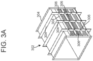
- FIGS. 3A and 3B illustrate ducting including heating tape.
- the ducting may by 1m x 1m, 3m x 3m, or some other size.
- Ducting includes an inside skin 302 and an outside skin 310.
- An insulation layer 308 may be located between the inside skin 302 and the outside skin 310.
- the insulation layer 308 may be located between protrusions 304 extending from the surface of the inside skin 302.
- Heating tape(s) 306 may be placed proximate to or coupled to at least one outer surface of the inside skin 302 of the ducting. In an example, the heating tape(s) 306 is located between an outer surface of the inside skin 302 and the insulation layer 308.
- heating tape 306 444 may be placed proximate to or coupled to the inside skin 302.
- the strips of heating tape 306 may be controlled as a single unit (e.g., may be selectively operated as a single unit) or a subset of the heating tape 306 may be selectively operated separate from other strips of the heating tape 306.
- the heating tape(s) 306 may be placed proximate to or coupled to the inside skin 302 of ducting located between the mixer 112 and the TAD/TAB 100 (and more particularly an air inlet of the hood 106). If the system includes more than one mixer 1 12, the heating tape(s) 306 may be placed proximate to or coupled to the inside skin 302 of ducting located after the last mixer 1 12 with respect to airflow (e.g., placed proximate to or coupled to the inside skin 302 of ducting located between the last mixer 112 and the TAD/TAB 100). However, one skilled in the art will appreciate that the heating tape(s) 306 may be implemented with other ducting of the system.
- the heating tape(s) 306 may be implemented along an entire distance (or implemented along a substantial distance) of the ducting between the mixer 112 and the TAD/TAB 100. Alternatively, the heating tape(s) 306 may only be placed proximate to or coupled to the ducting proximate to an air inlet of the hood 106.
- heating tape(s) 306 96+ placed proximate to or coupled to a particular section of ducting may depend on energy cost and/or a strategy for controlling the temperature of the boundary layer(s).
- heating tape(s) 306 may be uniformly implemented along all or nearly all of the length of the ducting from the mixer 112 to the TAD/TAB 100.
- the heating tape(s) 306 may maintain the boundary layer(s) at or substantially at a desired drying or bonding temperature over the duration of the ducting (e.g., the heating tape(s) 306 may be operated to maintain a desired uniform temperature distribution along the duration of the ducting).
- heating tape(s) 306 may only be placed proximate to or coupled to ducting proximate to the air inlet of the hood 106, or a thicker amount of heating tape(s) 306 may be placed proximate to or coupled to ducting proximate to the air inlet of the hood 106 than is implemented distant from the air inlet of the hood 106.
- the heating tape(s) 306 96+ may gradually increase the temperature of the boundary layer(s) of the air as the air gets closer to the air inlet of the hood 106 such that the air experiences a desired uniform temperature distribution by the time the air reaches the air inlet of the hood 106.
- heating tape(s) 306 may be implemented over the length of the ducting, as compared to simply implementing heating tape(s) 306 to ducting proximate to the air inlet of the hood 106.
- implementing heating tape(s) 306 over the entire length of the ducting between the last mixer 112 and the air inlet of the hood 106 may be beneficial because heat loss may be relatively constant along the length of the ducting.
- the cost of operating the heating tape(s) 306 may be a minimal consideration because the difference between the temperature of the boundary layer(s) and the desired temperature for drying or bonding material may only be a few degrees (e.g., +/- 2°C).
- the inside skin 302 may include four walls or surfaces that contact air traveling through the inside skin 302.
- the temperature profile of the air may be conical. That is, the boundary layers at or proximate each of the four walls of the inside skin 302 may have decreased temperature as compared to air located distant from the walls of the ducting.
- Heating tape(s) 306 may be placed proximate to or coupled to the outside surface of each of the four walls of the inside skin 302. Such implementation may result in the temperature profile of the air being completely planar (as illustrated by 206 in FIG. 2 ).
- heating tape(s) 306 may not be necessary to implement heating tape(s) 306 with respect to every wall of the inside skin 302.
- Two opposing (e.g., parallel) walls of the inside skin 302 may communicate with air that is ultimately exposed to edges of material to be dried or bonded on the foraminous cylinder 104 (as illustrated in FIG. 4 ).
- the other two opposing walls (that would extend along the plane of the paper on which FIG. 4 is illustrated) of the inside skin 302 may communicate with air that is ultimately exposed to non-edge portions of the material to be dried or bonded.
- heating tape(s) 306 may be beneficial to implement heating tape(s) 306 with respect to the walls of the inside skin 302 that communicate with the air that is exposed to the edges of the material to be dried or bonded, but may not be necessary to implement heating tape(s) 306 with respect to the walls of the inside skin 302 that communicate with air that is exposed to the non-edge portions of the material to be dried.
- the temperature profile of the air in the ducting may be arcuate.
- the arcuate temperature profile of the air may include two boundary layers, of decreased temperature, that extend along the plane of the paper on which FIG. 4 is illustrated.
- the boundary layers would extend parallel with the material to be dried or bonded on the foraminous cylinder 104.
- the entirety of the material (even the edges) would first be subject to a first boundary layer of decreased temperature, then subjected to the desired drying or bonding temperature, and then subjected to the second boundary layer of decreased temperature.
- the entirety of the material is subjected to the desired temperature for drying or bonding for a duration of time. Such may effectively dry or bond the material even though the material may also be subject to the decreased temperatures of the boundary layers.
- heating tape(s) 306 may be used to control the size of the decreased temperature boundary layers of the arcuate temperature profile and, as a result, change the amount of decreased temperature air and desired temperature air applied to the material to be dried or bonded.
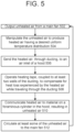
- FIG. 5 illustrates the use of heating tape(s) 306 to maintain a boundary layer(s) of air at or about a desired temperature for drying or bonding material while traveling through ducting.
- Unheated air is output (502) from the main fan 108.
- the unheated air is manipulated (504) to produce heated air having a desired uniform temperature distribution.
- the unheated air may be manipulated by passing the unheated air through at least one heater 110 and at least one mixer 112.
- the heated air having the desired uniform temperature distribution is sent (506), through ducting, to an air inlet of the hood 106.
- Heating tape(s) 306, coupled to at least two walls of the ducting, is operated (508) to compensate for heat loss experienced by the heated air while traveling through the ducting.
- the heating tape(s) 306 may be operated using at least one temperature sensor and a control loop.
- the at least one temperature sensor may be used to monitor the temperature of the heated air at or proximate at least one wall of the ducting.
- Heating tapes of different outputs may be used.
- the amount of heating tape(s) 306 used may depend on the output of the heating tape(s) 306, the amount of insulation in the ducting, material make-up of the ducting, etc.
- heating tape(s) 306 capable of producing stronger outputs may only need to cover about 50% of an area of ducting wall between the mixer 112 and the TAD/TAB 100, whereas heating tape(s) 306 capable of producing lesser outputs may need to cover more than about 50% (e.g., up to about 100%) of the area of the ducting to affect the boundary layer of the air in the same manner.
- heating tape(s) 306 need to maintain the boundary layer(s) at the desired temperature for drying or bonding may depend on the temperature of the air output by the mixer 112, the amount of insulation in the ducting, the material make-up of the ducting, etc.
- the heated air after passing through the ducting, is communicated (510) to material on the foraminous cylinder 104 in the hood 106.
- the heated air becomes unheated air after it passes through the material. At least some of this unheated air is circulated (512) to the main fan 108. This results in an airflow loop as illustrated in FIG. 1 .
Landscapes
- Engineering & Computer Science (AREA)
- Mechanical Engineering (AREA)
- General Engineering & Computer Science (AREA)
- Life Sciences & Earth Sciences (AREA)
- Microbiology (AREA)
- Sustainable Development (AREA)
- Textile Engineering (AREA)
- Drying Of Solid Materials (AREA)
Claims (15)
- Système de technologie aérienne (100), comprenant :un conduit qui reçoit de l'air chauffé,une hotte (106) conçue pour recevoir l'air chauffé provenant du conduit ; etun cylindre troué (104) entouré au moins partiellement par la hotte (106), le cylindre troué (104) conçu pour déplacer le matériau à travers la hotte (106), le matériau étant en contact avec l'air chauffé, caractérisé en ce que le conduit comporte au moins un ruban chauffant (306) situé à proximité de deux parois opposées du conduit, l'au moins un ruban chauffant (306) étant actionné de manière sélective pour compenser la perte de chaleur subie par l'air chauffé lors de son déplacement à travers le conduit.
- Système selon la revendication 1, dans lequel l'au moins un ruban chauffant (306) est :
situé le long d'une longueur du conduit depuis un premier emplacement où le conduit reçoit l'air chauffé jusqu'à un second emplacement où le conduit fournit l'air chauffé à la hotte (106). - Système selon la revendication 1, dans lequel l'au moins un ruban chauffant (306) est actionné de manière sélective pour chauffer les couches limites de l'air chauffé à une température subie par une partie de l'air chauffé située à l'écart des parois du conduit.
- Système selon la revendication 1, dans lequel les deux parois opposées du conduit sont en communication fluidique avec les bords extérieurs du matériau déplacé le long du cylindre troué (104).
- Système selon la revendication 1, dans lequel le conduit comprend :une peau intérieure (302),une peau extérieure (310), etune isolation (308) située entre la peau intérieure (302) et la peau extérieure (310),dans lequel l'au moins un ruban chauffant (306) est situé entre la peau intérieure (302) et l'isolation (308).
- Système selon la revendication 1, comprenant en outre :
un élément mélangeur (112) couplé au conduit, l'élément mélangeur (112) en communication fluidique avec un réchauffeur d'air (110), l'élément mélangeur (112) fonctionnant sur l'air chauffé pour générer un second air chauffé d'une distribution de température uniforme souhaitée, dans lequel au moins un ruban chauffant (306) est situé à partir d'un premier emplacement où le conduit se couple à l'élément mélangeur (112) jusqu'à un second emplacement où le conduit se couple à la hotte (106), l'au moins un ruban chauffant (306) fonctionnant sur toute la distance du conduit, du premier emplacement au second emplacement, pour compenser la perte de chaleur subie par l'air chauffé sur la distance. - Système selon la revendication 1, dans lequel l'au moins un ruban chauffant (306) est :
actionné à proximité de la hotte (106) pour compenser la perte de chaleur subie par l'air chauffé sur une distance du conduit. - Système selon la revendication 1, dans lequel les deux parois opposées du conduit sont en communication fluidique avec les bords extérieurs du matériau déplacé à travers la hotte (106) par le cylindre troué (104).
- Système selon la revendication 1, dans lequel la hotte (106) présente une largeur proportionnelle à la largeur du matériau déplacé à travers la hotte (106) par le cylindre troué (104).
- Système de technologie aérienne, comprenant :la sortie d'un premier air non chauffé à partir d'un ventilateur (108) ;la manipulation du premier air non chauffé pour produire de l'air chauffé présentant une distribution de température uniforme souhaitée ;l'envoi, à travers des canalisations, de l'air chauffé vers une entrée d'air d'une hotte (106) ;l'utilisation d'au moins un ruban chauffant (306), situé à proximité de deux parois parallèles du conduit, pour compenser la perte de chaleur subie par l'air chauffé lors de son déplacement à travers le conduit ;la communication de l'air chauffé à un matériau sur un cylindre troué (104) à l'intérieur de la hotte (106), l'air chauffé devenant un second air non chauffé à mesure qu'il sèche ou lie le matériau ; et faire circuler le second air non chauffé vers le ventilateur (108).
- Procédé selon la revendication 10, comprenant en outre :
le positionnement de l'au moins un ruban chauffant (306) entre une peau intérieure (302) du conduit et une couche d'isolation (308) du conduit. - Procédé selon la revendication 10, comprenant en outre :
le fait de faire fonctionner l'au moins un ruban chauffant (306) à proximité de la hotte (106) pour compenser la perte de chaleur subie par l'air chauffé sur une longueur du conduit. - Procédé selon la revendication 10,
dans lequel l'utilisation de l'au moins un ruban chauffant (306) comprend le fonctionnement sélectif de l'au moins un ruban chauffant (306) pour chauffer des couches limites de l'air chauffé à une température subie par une partie de l'air chauffé située à l'écart des surfaces du conduit. - Procédé selon la revendication 10, comprenant en outre :
la conception des deux parois parallèles du conduit pour qu'elles soient en communication fluidique avec les bords extérieurs du matériau déplacé le long du cylindre troué (104) . - Procédé selon la revendication 11, comprenant en outre :
la conception de la hotte (106) pour avoir une largeur proportionnelle à la largeur du matériau déplacé le long du cylindre troué (104).
Applications Claiming Priority (2)
| Application Number | Priority Date | Filing Date | Title |
|---|---|---|---|
| US201862678643P | 2018-05-31 | 2018-05-31 | |
| PCT/US2019/015357 WO2019231502A1 (fr) | 2018-05-31 | 2019-01-28 | Systèmes et procédés de séchage et de liaison à air traversant |
Publications (3)
| Publication Number | Publication Date |
|---|---|
| EP3802952A1 EP3802952A1 (fr) | 2021-04-14 |
| EP3802952A4 EP3802952A4 (fr) | 2022-07-06 |
| EP3802952B1 true EP3802952B1 (fr) | 2024-05-08 |
Family
ID=68694594
Family Applications (1)
| Application Number | Title | Priority Date | Filing Date |
|---|---|---|---|
| EP19810607.2A Active EP3802952B1 (fr) | 2018-05-31 | 2019-01-28 | Systèmes et procédés de séchage et de liaison à air traversant |
Country Status (4)
| Country | Link |
|---|---|
| US (1) | US10739072B2 (fr) |
| EP (1) | EP3802952B1 (fr) |
| CN (1) | CN112292489B (fr) |
| WO (1) | WO2019231502A1 (fr) |
Families Citing this family (4)
| Publication number | Priority date | Publication date | Assignee | Title |
|---|---|---|---|---|
| WO2019231502A1 (fr) * | 2018-05-31 | 2019-12-05 | Valmet, Inc. | Systèmes et procédés de séchage et de liaison à air traversant |
| US11662142B2 (en) | 2021-04-06 | 2023-05-30 | Cmpc Tissue S.A. | System for reheating air in dryers |
| CN115682422A (zh) * | 2021-07-22 | 2023-02-03 | 维美德公司 | 紧凑的高性能穿透式热风设备 |
| IT202200026457A1 (it) * | 2022-12-22 | 2024-06-22 | Toscotec S P A | Apparecchiatura per il trattamento di materiale cartaceo. |
Family Cites Families (27)
| Publication number | Priority date | Publication date | Assignee | Title |
|---|---|---|---|---|
| US3208158A (en) * | 1963-04-09 | 1965-09-28 | Hupp Corp | Dryers |
| GB1519265A (en) | 1975-04-09 | 1978-07-26 | Valmet Oy | Method and apparatus for treatment of a web in order to adjust the moisture content thereof |
| GB1589072A (en) * | 1977-04-05 | 1981-05-07 | Greenbank Cast Basalt Eng Co | Drying apparatus for paper making machines and other cylinder drying machines |
| DE3120738A1 (de) * | 1981-05-25 | 1982-12-09 | Windmöller & Hölscher, 4540 Lengerich | Verfahren und vorrichtung zum trocknen von bedruckten oder beschichteten bahnen. |
| US4501072A (en) * | 1983-07-11 | 1985-02-26 | Amjo, Inc. | Dryer and printed material and the like |
| DE4105978C2 (de) * | 1991-02-26 | 1997-01-30 | Escher Wyss Gmbh | Schutzhaube für Walzen |
| FI87669C (fi) * | 1992-03-02 | 1993-02-10 | Valmet Paper Machinery Inc | Foerfarande och tork vid torkning av papper |
| DE4342802C5 (de) * | 1993-12-15 | 2008-05-21 | Deutz Ag | Hubkolben-Brennkraftmaschine |
| US5657636A (en) * | 1996-02-01 | 1997-08-19 | Suggs; William G. | Supply air grill condensation elimination method and apparatus |
| DE69701148T2 (de) * | 1997-07-17 | 2000-09-21 | Hp-Chemie Pelzer Research And Development Ltd., Waterford | Diskontinuerliche Fertigung von geformten Verbundkörpern |
| FI116731B (fi) * | 2001-06-26 | 2006-02-15 | Metso Paper Inc | Päällepuhallusjärjestelmä paperikoneen tai vastaavan kuivatusosassa |
| US6668590B2 (en) * | 2001-10-23 | 2003-12-30 | Glasstech, Inc. | Forced convection heating furnace and method for heating glass sheets |
| US6964117B2 (en) * | 2002-12-20 | 2005-11-15 | Metso Paper Usa, Inc. | Method and apparatus for adjusting a moisture profile in a web |
| US20050085178A1 (en) * | 2003-08-26 | 2005-04-21 | Bruce Hall | System and method for preventing growth of mold or mildew in a building |
| US7225558B2 (en) * | 2004-07-30 | 2007-06-05 | Metso Paper Usa, Inc. | Cross-machine flow and profile control for through-air devices treating permeable webs |
| JP2006207847A (ja) * | 2005-01-25 | 2006-08-10 | Canon Inc | 温風乾燥装置 |
| US7861437B2 (en) * | 2006-02-27 | 2011-01-04 | Metso Paper Usa, Inc. | System and method for mixing distinct air streams |
| US8597555B2 (en) * | 2006-10-30 | 2013-12-03 | Ahlstrom Corporation | Method for manufacturing soft, resistant and bulky nonwoven and nonwoven thus obtained |
| DE102007006960A1 (de) * | 2007-02-13 | 2008-08-14 | Voith Patent Gmbh | Vorrichtung zur Trocknung einer Faserstoffbahn |
| AU2012301903B2 (en) * | 2011-08-30 | 2015-07-09 | Watlow Electric Manufacturing Company | High definition heater system having a fluid medium |
| US8869420B1 (en) * | 2012-11-19 | 2014-10-28 | Mousa Mohammad Nazhad | Energy-efficient process and apparatus for drying feedstock |
| EP3158130B1 (fr) * | 2014-07-29 | 2018-03-28 | Siemens Aktiengesellschaft | Procédé et dispositif de séchage d'un produit à sécher et installation industrielle |
| FR3030705A1 (fr) * | 2014-12-17 | 2016-06-24 | Andritz Perfojet Sas | Installation de sechage d'un voile de non-tisse humide |
| JP2017122514A (ja) * | 2016-01-05 | 2017-07-13 | 大阪瓦斯株式会社 | 暖房システム |
| US10533283B2 (en) * | 2017-07-18 | 2020-01-14 | Valmet, Inc. | Reduced diameter foraminous exhaust cylinder |
| JP7089911B2 (ja) * | 2018-03-22 | 2022-06-23 | 株式会社Screenホールディングス | 乾燥装置及びそれを備えたインクジェット印刷装置 |
| WO2019231502A1 (fr) * | 2018-05-31 | 2019-12-05 | Valmet, Inc. | Systèmes et procédés de séchage et de liaison à air traversant |
-
2019
- 2019-01-28 WO PCT/US2019/015357 patent/WO2019231502A1/fr not_active Ceased
- 2019-01-28 US US16/259,119 patent/US10739072B2/en active Active
- 2019-01-28 CN CN201980036462.XA patent/CN112292489B/zh active Active
- 2019-01-28 EP EP19810607.2A patent/EP3802952B1/fr active Active
Also Published As
| Publication number | Publication date |
|---|---|
| EP3802952A4 (fr) | 2022-07-06 |
| US20190368812A1 (en) | 2019-12-05 |
| WO2019231502A1 (fr) | 2019-12-05 |
| CN112292489B (zh) | 2021-11-09 |
| US10739072B2 (en) | 2020-08-11 |
| CN112292489A (zh) | 2021-01-29 |
| EP3802952A1 (fr) | 2021-04-14 |
Similar Documents
| Publication | Publication Date | Title |
|---|---|---|
| EP3802952B1 (fr) | Systèmes et procédés de séchage et de liaison à air traversant | |
| CN107421297B (zh) | 用于纺织织物幅面的具有经改进的用于热量输入的装置的烘干装置 | |
| US10113268B2 (en) | Installation for drying a damp non-woven web | |
| JP2005503279A (ja) | 石膏プラスタボードを乾燥させるための装置 | |
| US9885519B2 (en) | Method and installation for drying a damp web | |
| US6116895A (en) | Dual mode convection oven | |
| JP7723769B2 (ja) | 高温空気導入を用いたスルーエア乾燥システムおよび方法 | |
| JP6127723B2 (ja) | 乾燥制御システム、乾燥機、乾燥制御方法、乾燥方法 | |
| JP7621722B2 (ja) | 熱処理装置 | |
| CN103015249B (zh) | 烘干移动幅材的烘干设备和方法 | |
| EP1774235B1 (fr) | Commande de flux transversal et de profil pour des dispositifs a air traversant traitant des bandes permeables | |
| CA2644043C (fr) | Systeme et procede de melange de flux d'air distincts | |
| CN104583698A (zh) | 用于干燥施加到基材上的液体膜的方法和设备 | |
| CN117425803A (zh) | 用于减少环境空气的渗透的穿透式热风设备 | |
| KR20140068039A (ko) | 기판에 도포된 유체막을 건조하는 방법 및 장치 | |
| US8176650B2 (en) | Method for warming up or cooling down a through-air dryer | |
| US20020096804A1 (en) | Method for convectively heating permeable material | |
| RU2382306C1 (ru) | Автоматизированная установка для сушки нетканых материалов с волокнистой и пористой структурой | |
| WO2010043061A3 (fr) | Dispositif de récupération de chaleur sur une installation de traitement thermique de bandes textiles | |
| CN213873679U (zh) | 烘干机 | |
| US20220112661A1 (en) | Through-air apparatus with adjustable deckle | |
| JPH02110282A (ja) | 布帛又はシート状繊維材料の高周波乾燥装置 | |
| US20110185589A1 (en) | Device and method for thermally processing web-like fabric webs | |
| CN201517842U (zh) | 空气加热通道以及包含该通道的织物烘干设备 | |
| IT202200026445A1 (it) | Macchina per la produzione della carta. |
Legal Events
| Date | Code | Title | Description |
|---|---|---|---|
| STAA | Information on the status of an ep patent application or granted ep patent |
Free format text: STATUS: THE INTERNATIONAL PUBLICATION HAS BEEN MADE |
|
| PUAI | Public reference made under article 153(3) epc to a published international application that has entered the european phase |
Free format text: ORIGINAL CODE: 0009012 |
|
| STAA | Information on the status of an ep patent application or granted ep patent |
Free format text: STATUS: REQUEST FOR EXAMINATION WAS MADE |
|
| 17P | Request for examination filed |
Effective date: 20201230 |
|
| AK | Designated contracting states |
Kind code of ref document: A1 Designated state(s): AL AT BE BG CH CY CZ DE DK EE ES FI FR GB GR HR HU IE IS IT LI LT LU LV MC MK MT NL NO PL PT RO RS SE SI SK SM TR |
|
| AX | Request for extension of the european patent |
Extension state: BA ME |
|
| DAV | Request for validation of the european patent (deleted) | ||
| DAX | Request for extension of the european patent (deleted) | ||
| A4 | Supplementary search report drawn up and despatched |
Effective date: 20220603 |
|
| RIC1 | Information provided on ipc code assigned before grant |
Ipc: F26B 13/16 20060101ALI20220530BHEP Ipc: D21F 11/14 20060101ALI20220530BHEP Ipc: H05B 3/56 20060101ALI20220530BHEP Ipc: F26B 23/06 20060101ALI20220530BHEP Ipc: F26B 23/02 20060101ALI20220530BHEP Ipc: F26B 3/02 20060101ALI20220530BHEP Ipc: F24F 13/02 20060101ALI20220530BHEP Ipc: D21F 5/18 20060101ALI20220530BHEP Ipc: D21F 5/16 20060101ALI20220530BHEP Ipc: D21F 5/00 20060101AFI20220530BHEP |
|
| P01 | Opt-out of the competence of the unified patent court (upc) registered |
Effective date: 20230527 |
|
| GRAP | Despatch of communication of intention to grant a patent |
Free format text: ORIGINAL CODE: EPIDOSNIGR1 |
|
| STAA | Information on the status of an ep patent application or granted ep patent |
Free format text: STATUS: GRANT OF PATENT IS INTENDED |
|
| INTG | Intention to grant announced |
Effective date: 20240228 |
|
| RAP3 | Party data changed (applicant data changed or rights of an application transferred) |
Owner name: VALMET, INC. |
|
| GRAS | Grant fee paid |
Free format text: ORIGINAL CODE: EPIDOSNIGR3 |
|
| GRAA | (expected) grant |
Free format text: ORIGINAL CODE: 0009210 |
|
| STAA | Information on the status of an ep patent application or granted ep patent |
Free format text: STATUS: THE PATENT HAS BEEN GRANTED |
|
| AK | Designated contracting states |
Kind code of ref document: B1 Designated state(s): AL AT BE BG CH CY CZ DE DK EE ES FI FR GB GR HR HU IE IS IT LI LT LU LV MC MK MT NL NO PL PT RO RS SE SI SK SM TR |
|
| REG | Reference to a national code |
Ref country code: GB Ref legal event code: FG4D |
|
| REG | Reference to a national code |
Ref country code: CH Ref legal event code: EP |
|
| REG | Reference to a national code |
Ref country code: DE Ref legal event code: R096 Ref document number: 602019052021 Country of ref document: DE |
|
| REG | Reference to a national code |
Ref country code: IE Ref legal event code: FG4D |
|
| REG | Reference to a national code |
Ref country code: NL Ref legal event code: FP |
|
| REG | Reference to a national code |
Ref country code: LT Ref legal event code: MG9D |
|
| PG25 | Lapsed in a contracting state [announced via postgrant information from national office to epo] |
Ref country code: IS Free format text: LAPSE BECAUSE OF FAILURE TO SUBMIT A TRANSLATION OF THE DESCRIPTION OR TO PAY THE FEE WITHIN THE PRESCRIBED TIME-LIMIT Effective date: 20240908 |
|
| PG25 | Lapsed in a contracting state [announced via postgrant information from national office to epo] |
Ref country code: BG Free format text: LAPSE BECAUSE OF FAILURE TO SUBMIT A TRANSLATION OF THE DESCRIPTION OR TO PAY THE FEE WITHIN THE PRESCRIBED TIME-LIMIT Effective date: 20240508 |
|
| PG25 | Lapsed in a contracting state [announced via postgrant information from national office to epo] |
Ref country code: HR Free format text: LAPSE BECAUSE OF FAILURE TO SUBMIT A TRANSLATION OF THE DESCRIPTION OR TO PAY THE FEE WITHIN THE PRESCRIBED TIME-LIMIT Effective date: 20240508 Ref country code: FI Free format text: LAPSE BECAUSE OF FAILURE TO SUBMIT A TRANSLATION OF THE DESCRIPTION OR TO PAY THE FEE WITHIN THE PRESCRIBED TIME-LIMIT Effective date: 20240508 |
|
| PG25 | Lapsed in a contracting state [announced via postgrant information from national office to epo] |
Ref country code: GR Free format text: LAPSE BECAUSE OF FAILURE TO SUBMIT A TRANSLATION OF THE DESCRIPTION OR TO PAY THE FEE WITHIN THE PRESCRIBED TIME-LIMIT Effective date: 20240809 |
|
| PG25 | Lapsed in a contracting state [announced via postgrant information from national office to epo] |
Ref country code: PT Free format text: LAPSE BECAUSE OF FAILURE TO SUBMIT A TRANSLATION OF THE DESCRIPTION OR TO PAY THE FEE WITHIN THE PRESCRIBED TIME-LIMIT Effective date: 20240909 |
|
| REG | Reference to a national code |
Ref country code: AT Ref legal event code: MK05 Ref document number: 1685075 Country of ref document: AT Kind code of ref document: T Effective date: 20240508 |
|
| PG25 | Lapsed in a contracting state [announced via postgrant information from national office to epo] |
Ref country code: ES Free format text: LAPSE BECAUSE OF FAILURE TO SUBMIT A TRANSLATION OF THE DESCRIPTION OR TO PAY THE FEE WITHIN THE PRESCRIBED TIME-LIMIT Effective date: 20240508 |
|
| PG25 | Lapsed in a contracting state [announced via postgrant information from national office to epo] |
Ref country code: AT Free format text: LAPSE BECAUSE OF FAILURE TO SUBMIT A TRANSLATION OF THE DESCRIPTION OR TO PAY THE FEE WITHIN THE PRESCRIBED TIME-LIMIT Effective date: 20240508 |
|
| PG25 | Lapsed in a contracting state [announced via postgrant information from national office to epo] |
Ref country code: PL Free format text: LAPSE BECAUSE OF FAILURE TO SUBMIT A TRANSLATION OF THE DESCRIPTION OR TO PAY THE FEE WITHIN THE PRESCRIBED TIME-LIMIT Effective date: 20240508 |
|
| PG25 | Lapsed in a contracting state [announced via postgrant information from national office to epo] |
Ref country code: LV Free format text: LAPSE BECAUSE OF FAILURE TO SUBMIT A TRANSLATION OF THE DESCRIPTION OR TO PAY THE FEE WITHIN THE PRESCRIBED TIME-LIMIT Effective date: 20240508 |
|
| PG25 | Lapsed in a contracting state [announced via postgrant information from national office to epo] |
Ref country code: PT Free format text: LAPSE BECAUSE OF FAILURE TO SUBMIT A TRANSLATION OF THE DESCRIPTION OR TO PAY THE FEE WITHIN THE PRESCRIBED TIME-LIMIT Effective date: 20240909 Ref country code: PL Free format text: LAPSE BECAUSE OF FAILURE TO SUBMIT A TRANSLATION OF THE DESCRIPTION OR TO PAY THE FEE WITHIN THE PRESCRIBED TIME-LIMIT Effective date: 20240508 Ref country code: NO Free format text: LAPSE BECAUSE OF FAILURE TO SUBMIT A TRANSLATION OF THE DESCRIPTION OR TO PAY THE FEE WITHIN THE PRESCRIBED TIME-LIMIT Effective date: 20240808 Ref country code: LV Free format text: LAPSE BECAUSE OF FAILURE TO SUBMIT A TRANSLATION OF THE DESCRIPTION OR TO PAY THE FEE WITHIN THE PRESCRIBED TIME-LIMIT Effective date: 20240508 Ref country code: IS Free format text: LAPSE BECAUSE OF FAILURE TO SUBMIT A TRANSLATION OF THE DESCRIPTION OR TO PAY THE FEE WITHIN THE PRESCRIBED TIME-LIMIT Effective date: 20240908 Ref country code: HR Free format text: LAPSE BECAUSE OF FAILURE TO SUBMIT A TRANSLATION OF THE DESCRIPTION OR TO PAY THE FEE WITHIN THE PRESCRIBED TIME-LIMIT Effective date: 20240508 Ref country code: GR Free format text: LAPSE BECAUSE OF FAILURE TO SUBMIT A TRANSLATION OF THE DESCRIPTION OR TO PAY THE FEE WITHIN THE PRESCRIBED TIME-LIMIT Effective date: 20240809 Ref country code: FI Free format text: LAPSE BECAUSE OF FAILURE TO SUBMIT A TRANSLATION OF THE DESCRIPTION OR TO PAY THE FEE WITHIN THE PRESCRIBED TIME-LIMIT Effective date: 20240508 Ref country code: ES Free format text: LAPSE BECAUSE OF FAILURE TO SUBMIT A TRANSLATION OF THE DESCRIPTION OR TO PAY THE FEE WITHIN THE PRESCRIBED TIME-LIMIT Effective date: 20240508 Ref country code: BG Free format text: LAPSE BECAUSE OF FAILURE TO SUBMIT A TRANSLATION OF THE DESCRIPTION OR TO PAY THE FEE WITHIN THE PRESCRIBED TIME-LIMIT Effective date: 20240508 Ref country code: AT Free format text: LAPSE BECAUSE OF FAILURE TO SUBMIT A TRANSLATION OF THE DESCRIPTION OR TO PAY THE FEE WITHIN THE PRESCRIBED TIME-LIMIT Effective date: 20240508 Ref country code: RS Free format text: LAPSE BECAUSE OF FAILURE TO SUBMIT A TRANSLATION OF THE DESCRIPTION OR TO PAY THE FEE WITHIN THE PRESCRIBED TIME-LIMIT Effective date: 20240808 |
|
| PG25 | Lapsed in a contracting state [announced via postgrant information from national office to epo] |
Ref country code: DK Free format text: LAPSE BECAUSE OF FAILURE TO SUBMIT A TRANSLATION OF THE DESCRIPTION OR TO PAY THE FEE WITHIN THE PRESCRIBED TIME-LIMIT Effective date: 20240508 |
|
| PG25 | Lapsed in a contracting state [announced via postgrant information from national office to epo] |
Ref country code: EE Free format text: LAPSE BECAUSE OF FAILURE TO SUBMIT A TRANSLATION OF THE DESCRIPTION OR TO PAY THE FEE WITHIN THE PRESCRIBED TIME-LIMIT Effective date: 20240508 |
|
| PG25 | Lapsed in a contracting state [announced via postgrant information from national office to epo] |
Ref country code: CZ Free format text: LAPSE BECAUSE OF FAILURE TO SUBMIT A TRANSLATION OF THE DESCRIPTION OR TO PAY THE FEE WITHIN THE PRESCRIBED TIME-LIMIT Effective date: 20240508 |
|
| PG25 | Lapsed in a contracting state [announced via postgrant information from national office to epo] |
Ref country code: RO Free format text: LAPSE BECAUSE OF FAILURE TO SUBMIT A TRANSLATION OF THE DESCRIPTION OR TO PAY THE FEE WITHIN THE PRESCRIBED TIME-LIMIT Effective date: 20240508 Ref country code: SK Free format text: LAPSE BECAUSE OF FAILURE TO SUBMIT A TRANSLATION OF THE DESCRIPTION OR TO PAY THE FEE WITHIN THE PRESCRIBED TIME-LIMIT Effective date: 20240508 |
|
| PG25 | Lapsed in a contracting state [announced via postgrant information from national office to epo] |
Ref country code: SM Free format text: LAPSE BECAUSE OF FAILURE TO SUBMIT A TRANSLATION OF THE DESCRIPTION OR TO PAY THE FEE WITHIN THE PRESCRIBED TIME-LIMIT Effective date: 20240508 |
|
| PG25 | Lapsed in a contracting state [announced via postgrant information from national office to epo] |
Ref country code: SM Free format text: LAPSE BECAUSE OF FAILURE TO SUBMIT A TRANSLATION OF THE DESCRIPTION OR TO PAY THE FEE WITHIN THE PRESCRIBED TIME-LIMIT Effective date: 20240508 Ref country code: SK Free format text: LAPSE BECAUSE OF FAILURE TO SUBMIT A TRANSLATION OF THE DESCRIPTION OR TO PAY THE FEE WITHIN THE PRESCRIBED TIME-LIMIT Effective date: 20240508 Ref country code: RO Free format text: LAPSE BECAUSE OF FAILURE TO SUBMIT A TRANSLATION OF THE DESCRIPTION OR TO PAY THE FEE WITHIN THE PRESCRIBED TIME-LIMIT Effective date: 20240508 Ref country code: EE Free format text: LAPSE BECAUSE OF FAILURE TO SUBMIT A TRANSLATION OF THE DESCRIPTION OR TO PAY THE FEE WITHIN THE PRESCRIBED TIME-LIMIT Effective date: 20240508 Ref country code: DK Free format text: LAPSE BECAUSE OF FAILURE TO SUBMIT A TRANSLATION OF THE DESCRIPTION OR TO PAY THE FEE WITHIN THE PRESCRIBED TIME-LIMIT Effective date: 20240508 Ref country code: CZ Free format text: LAPSE BECAUSE OF FAILURE TO SUBMIT A TRANSLATION OF THE DESCRIPTION OR TO PAY THE FEE WITHIN THE PRESCRIBED TIME-LIMIT Effective date: 20240508 |
|
| REG | Reference to a national code |
Ref country code: DE Ref legal event code: R097 Ref document number: 602019052021 Country of ref document: DE |
|
| PLBE | No opposition filed within time limit |
Free format text: ORIGINAL CODE: 0009261 |
|
| STAA | Information on the status of an ep patent application or granted ep patent |
Free format text: STATUS: NO OPPOSITION FILED WITHIN TIME LIMIT |
|
| 26N | No opposition filed |
Effective date: 20250211 |
|
| PG25 | Lapsed in a contracting state [announced via postgrant information from national office to epo] |
Ref country code: SI Free format text: LAPSE BECAUSE OF FAILURE TO SUBMIT A TRANSLATION OF THE DESCRIPTION OR TO PAY THE FEE WITHIN THE PRESCRIBED TIME-LIMIT Effective date: 20240508 |
|
| REG | Reference to a national code |
Ref country code: CH Ref legal event code: PL |
|
| PG25 | Lapsed in a contracting state [announced via postgrant information from national office to epo] |
Ref country code: SE Free format text: LAPSE BECAUSE OF FAILURE TO SUBMIT A TRANSLATION OF THE DESCRIPTION OR TO PAY THE FEE WITHIN THE PRESCRIBED TIME-LIMIT Effective date: 20240508 |
|
| PG25 | Lapsed in a contracting state [announced via postgrant information from national office to epo] |
Ref country code: LU Free format text: LAPSE BECAUSE OF NON-PAYMENT OF DUE FEES Effective date: 20250128 Ref country code: MC Free format text: LAPSE BECAUSE OF FAILURE TO SUBMIT A TRANSLATION OF THE DESCRIPTION OR TO PAY THE FEE WITHIN THE PRESCRIBED TIME-LIMIT Effective date: 20240508 |
|
| GBPC | Gb: european patent ceased through non-payment of renewal fee |
Effective date: 20250128 |
|
| PG25 | Lapsed in a contracting state [announced via postgrant information from national office to epo] |
Ref country code: GB Free format text: LAPSE BECAUSE OF NON-PAYMENT OF DUE FEES Effective date: 20250128 Ref country code: BE Free format text: LAPSE BECAUSE OF NON-PAYMENT OF DUE FEES Effective date: 20250131 |
|
| PG25 | Lapsed in a contracting state [announced via postgrant information from national office to epo] |
Ref country code: FR Free format text: LAPSE BECAUSE OF NON-PAYMENT OF DUE FEES Effective date: 20250131 |
|
| PG25 | Lapsed in a contracting state [announced via postgrant information from national office to epo] |
Ref country code: CH Free format text: LAPSE BECAUSE OF NON-PAYMENT OF DUE FEES Effective date: 20250131 |
|
| REG | Reference to a national code |
Ref country code: BE Ref legal event code: MM Effective date: 20250131 |
|
| PG25 | Lapsed in a contracting state [announced via postgrant information from national office to epo] |
Ref country code: IE Free format text: LAPSE BECAUSE OF NON-PAYMENT OF DUE FEES Effective date: 20250128 |
|
| PGFP | Annual fee paid to national office [announced via postgrant information from national office to epo] |
Ref country code: NL Payment date: 20260126 Year of fee payment: 8 |
|
| PGFP | Annual fee paid to national office [announced via postgrant information from national office to epo] |
Ref country code: DE Payment date: 20260128 Year of fee payment: 8 |
|
| PGFP | Annual fee paid to national office [announced via postgrant information from national office to epo] |
Ref country code: IT Payment date: 20260121 Year of fee payment: 8 |