EP3803473B1 - Système de commande pour équipement marin remorqué dirigeable - Google Patents
Système de commande pour équipement marin remorqué dirigeable Download PDFInfo
- Publication number
- EP3803473B1 EP3803473B1 EP19733383.4A EP19733383A EP3803473B1 EP 3803473 B1 EP3803473 B1 EP 3803473B1 EP 19733383 A EP19733383 A EP 19733383A EP 3803473 B1 EP3803473 B1 EP 3803473B1
- Authority
- EP
- European Patent Office
- Prior art keywords
- piece
- marine equipment
- towed marine
- disturbance
- towed
- Prior art date
- Legal status (The legal status is an assumption and is not a legal conclusion. Google has not performed a legal analysis and makes no representation as to the accuracy of the status listed.)
- Active
Links
Images


Classifications
-
- G—PHYSICS
- G05—CONTROLLING; REGULATING
- G05D—SYSTEMS FOR CONTROLLING OR REGULATING NON-ELECTRIC VARIABLES
- G05D1/00—Control of position, course, altitude or attitude of land, water, air or space vehicles, e.g. using automatic pilots
- G05D1/60—Intended control result
- G05D1/69—Coordinated control of the position or course of two or more vehicles
-
- B—PERFORMING OPERATIONS; TRANSPORTING
- B63—SHIPS OR OTHER WATERBORNE VESSELS; RELATED EQUIPMENT
- B63B—SHIPS OR OTHER WATERBORNE VESSELS; EQUIPMENT FOR SHIPPING
- B63B21/00—Tying-up; Shifting, towing, or pushing equipment; Anchoring
- B63B21/56—Towing or pushing equipment
- B63B21/66—Equipment specially adapted for towing underwater objects or vessels, e.g. fairings for tow-cables
-
- B—PERFORMING OPERATIONS; TRANSPORTING
- B63—SHIPS OR OTHER WATERBORNE VESSELS; RELATED EQUIPMENT
- B63B—SHIPS OR OTHER WATERBORNE VESSELS; EQUIPMENT FOR SHIPPING
- B63B49/00—Arrangements of nautical instruments or navigational aids
-
- G—PHYSICS
- G01—MEASURING; TESTING
- G01V—GEOPHYSICS; GRAVITATIONAL MEASUREMENTS; DETECTING MASSES OR OBJECTS; TAGS
- G01V1/00—Seismology; Seismic or acoustic prospecting or detecting
- G01V1/38—Seismology; Seismic or acoustic prospecting or detecting specially adapted for water-covered areas
- G01V1/3817—Positioning of seismic devices
- G01V1/3826—Positioning of seismic devices dynamic steering, e.g. by paravanes or birds
-
- B—PERFORMING OPERATIONS; TRANSPORTING
- B63—SHIPS OR OTHER WATERBORNE VESSELS; RELATED EQUIPMENT
- B63B—SHIPS OR OTHER WATERBORNE VESSELS; EQUIPMENT FOR SHIPPING
- B63B2211/00—Applications
- B63B2211/02—Oceanography
-
- G—PHYSICS
- G01—MEASURING; TESTING
- G01V—GEOPHYSICS; GRAVITATIONAL MEASUREMENTS; DETECTING MASSES OR OBJECTS; TAGS
- G01V2210/00—Details of seismic processing or analysis
- G01V2210/10—Aspects of acoustic signal generation or detection
- G01V2210/12—Signal generation
- G01V2210/129—Source location
- G01V2210/1293—Sea
-
- G—PHYSICS
- G01—MEASURING; TESTING
- G01V—GEOPHYSICS; GRAVITATIONAL MEASUREMENTS; DETECTING MASSES OR OBJECTS; TAGS
- G01V2210/00—Details of seismic processing or analysis
- G01V2210/10—Aspects of acoustic signal generation or detection
- G01V2210/14—Signal detection
- G01V2210/142—Receiver location
- G01V2210/1423—Sea
Definitions
- Such towed equipment may include, but is not limited to, dynamically controlled foil and hydrofoil systems configured to position and maintain spacing between seismic sources and other elements of a marine seismic array.
- Seismic arrays with sources and streamers are used to study rock strata and other structures below the surface, for example, as described in U.S. Patent Publication No. 2014/0247691 .
- One or more marine vessels are typically used to tow the source and/or receiver arrays, in order to obtain relevant geological data covering a desired surface area of the ocean floor.
- a single surface vessel may simultaneously tow both a source array and an array of seismic streamers, or different vessels can be used to tow separate source and receiver arrays.
- a towed source array can be used in conjunction with stationary receivers, for example, an array of ocean-bottom nodes, or with ocean-bottom cables deployed on the seabed.
- acoustic shock waves generated by the source array propagate through the water to penetrate the ocean floor and are reflected from subsurface structures.
- the reflected acoustic waves are recorded as signals or seismic responses by the receivers, e.g., hydrophones and/or geophones towed behind a vessel or deployed on the ocean floor.
- the receivers e.g., hydrophones and/or geophones towed behind a vessel or deployed on the ocean floor.
- the receivers e.g., hydrophones and/or geophones towed behind a vessel or deployed on the ocean floor.
- the receivers e.g., hydrophones and/or geophones towed behind a vessel or deployed on the ocean floor.
- the receivers e.g., hydrophones and/or geophones towed behind a vessel or deployed on the ocean floor.
- the towed marine equipment such as cables with seismic sensors and other equipment closely follow a predetermined course, e.g., in order to accurately
- Lateral forces are applied to maintain position and spacing of the seismic sources and other array elements as they are towed behind the vessel.
- the spacing depends on the number of sources and/or streamer cables that are deployed, and on the spacing between adjacent source and/or receiver components.
- a number of source sub-arrays or strings are deployed behind the vessel using a tow rope configuration to spread the sources over lateral distances of approximately ten to one hundred meters or more.
- Streamer cables are typically deployed over much larger lateral distances, for example, from one hundred meters to a kilometer or more, and may extend for several kilometers behind the tow vessel.
- Lateral spacing can be achieved by deploying a paravane or diverter apparatus on a dedicated tow rope arrangement using a spreader or series of individual tether lines to provide the desired spacing between adjacent cables.
- Positioning devices can also be provided along each streamer cable, in order to maintain depth and/or lateral offset along the cable length.
- a dynamically controlled, steerable foil system such as described in U.S. Patent Application Publication No. 2017/0106946 , may be used for steering and positioning such towed equipment in a marine seismic array.
- control systems for the steering actuators on such steering devices attempt to correct for position errors by using feedback information from sensors on the steering devices.
- This feedback information is helpful for determining actual position and speed and direction of travel of the steering devices.
- such information is often not adequate to quickly counteract changes in forces that may affect the positions of cables and sensors, for example, changes in currents, changes in speed and direction of the tow vessel, or other disturbances.
- the cables and sensors in a marine array may be out of position from a desired position for a longer period of time than acceptable due to such disturbances, which take a longer period of time or more cycles to correct by reliance solely on feedback loopdata.
- a control system for providing steering control commands to a steering actuator of a steering device on a piece of towed marine equipment comprising a memory storing setpoint data including positional data for a desired position of the piece of towed marine equipment and/or one or more components of the piece of towed marine equipment; a control module configured to receive the setpoint data, receive process data representing a calculated actual position of the piece of towed marine equipment and/or one or more components of the piece of towed marine equipment, compute a difference between the received setpoint data and the received process data and calculate a control command for the steering actuator of the steering device if there is a difference between the setpoint data and the process data; a disturbance adjustment calculation module configured to combine a disturbance value based upon a measured disturbance with a value of the process data and output a disturbance adjustment value, wherein the disturbance adjustment value is a quotient with the disturbance value in the numerator and the process data value in the denominator; and a correction calculator module
- a method in a control system for providing steering control commands to a steering actuator of a steering device on a piece of towed marine equipment comprising accessing setpoint data including positional values for a desired position of the piece of towed marine equipment and/or one or more components of the piece of towed marine equipment stored within a memory in the control system; receiving process data representing a calculated actual position of the piece of towed marine equipment and/or one or more components of the piece of towed marine equipment; computing a difference between the received setpoint data and the received process data; calculating a control command for the steering actuator of the steering device if there is a difference between the setpoint data and the process data within acontroller; combining a disturbance value of a measured disturbance with a value of the process data to calculate a disturbance adjustment value, wherein the disturbance adjustment value is a quotient with the disturbance value in the numerator and the process data value in the denominator; adding the disturbance adjustment value to the control command create an
- the measured disturbance data may include one or more of the following: a heading of a vessel towing the piece of towed marine equipment; a speed of the vessel towing the piece of towed marine equipment; a speed of a current affecting the vessel or the piece of towed marine equipment in a body of water in which the vessel and piece of towed marine equipment are deployed; or a direction of a current affecting the vessel or the piece of towed marine equipment in a body of water in which the vessel and piece of towed marine equipment are deployed.
- FIG. 1A A schematic illustration of a representative towed seismic array 70 utilizing one or more dynamically controlled foil systems 20 for steering source and/or streamer components is depicted in FIG. 1A .
- the seismic array 70 includes a source array 10 and a streamer array 72 towed by a seismic survey craft or other vessel 12.
- Tow lines or cables 14 are coupled to the vessel 12 at one end and attached to a sub-array or string 16 of seismic sources at the other.
- each tow cable 14 can be coupled to a series of air guns or other sources suspended from a head float, buoy, or other flotation apparatus 18.
- the source array 10 is directed along a navigational course or sail line by the tow vessel 12. Within the source array 10, the relative positions of the individual sources (or sets of sources) can be controlled by providing a dynamically steerable foil system for each floatation apparatus 18, or for groupings of floatation apparatus 18, as described herein.
- the source array 10 includes a number of head/sausage type floats 18 from which individual seismic sources 22 are suspended with umbilical cables 28 for power, data, and pneumatic connections to the survey vessel 12.
- the streamer array 72 includes a plurality of individual streamer cables 73 with seismic receivers distributed along each cable length to observe the reflected signals from the seismic sources 22.
- the streamer cables 73 are coupled to tow lines or other submerged cables 44 along a spreader or separation rope 74, which is suspended at a streamer depth below corresponding head buoys 75 using tag lines or depth ropes 76.
- the streamers 73 may extend many kilometers from the head buoys 75 toward a corresponding number of tail buoys 77 at the aft end. (Thus, FIG. 1A is not to scale).
- the separation rope 74 is laterally extended by attachment to spur lines 78, which are coupled to paravanes or diverters 80 via deflector straps 81.
- Wide tow ropes 82 run between paravanes or diverters 80 and the tow vessel 12.
- the dynamically controllable foil system 20 may be provided on or in place of one or more streamer tag lines or depth ropes 76, extending from the head buoys 75 down to the forward end of the streamer cables 73.
- the steerable foil systems 20 may also be provided between the tail buoys 77 and the aft ends of the streamer cables 73 and in intermediate streamer locations.
- the seismic survey vessel 12 is provided with a navigational system 86 including one or more foil steering modules configured to communicate with the dynamically steerable foil systems 20 deployed variously in the source array 10 and the streamer array 72, and/or among the other components of the towed seismic array 70.
- the foil systems 20 can also be utilized, in addition to source steering, to independently steer and laterally position streamers 73 with or without a discrete spreader or separation rope 74.
- the steerable foil systems 20 can also be provided in lieu of diverters or paravanes 80, for example in the end streamer positions as shown in FIG. 1A , without the need for a separate spur line 78 and wide tow rope 82.
- the steerable foil systems 20 can be used within or provided in place of one or more diverters or paravanes 80 using a similar spur cable configuration.
- the foil system 20 can be utilized for steering a wide range of submerged cable and float arrangements, suitable not only to seismic source and streamer steering but also for ocean-bottom cable and node deployment, side scan surveys, and sonar applications.
- the dynamically steerable foil system 20 may also be adapted to more generalized (non-seismic) uses including generic paravane, diverter and hydrofoil systems. Use with the paravane/diverter cable or P-cable and ocean bottom cables are additional options.
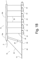
- FIG. 1B is a side view of a source array 10 illustrating representative configurations for dynamically controlled foil system 20.
- a sub-array or string 16 of individual air guns or other seismic sources 22 is suspended from the floatation apparatus 18 via suspension ropes 24, which determine the depth of sources 22 below surface S.
- Suspension ropes 24 are coupled to selected portions of the float 18, e.g., between head float section 18a and the trailing end of sausage float section 18b.
- the float 18 is towed along the surface S via the tow cable 14, which is coupled to the head float section 18 a via a tow leader 26.
- the tow cable 14 typically comprises an umbilical 28 with data and power connections for seismic sources 22 and is connected to the foil system 20 at a cable connector 29.
- the umbilical 28 may include a pneumatic hose or conduit configured to provide pressurized air to the seismic sources 22 in order to generate acoustic shock waves when fired in response to direction by a control system.
- the shock waves (or other seismic signals) propagate from the seismic sources 22 through the water or other medium, penetrating the ocean floor and reflecting back from subsurface features.
- the reflected signals are recorded by seismic sensors (e.g., hydrophones or geophones in a streamer cable or ocean-bottom array) and processed to generate geophysical image data representing the subsurface structures.
- the dynamically controlled foil system 20 can be coupled between the floatation apparatus 18 and a submerged portion of the tow cable 14, e.g., at the cable connector 29 between the head float 18 a and the umbilical portion 28 of the tow cable 14, aft of the tow leader 26 and forward of the seismic sources 22.
- the submerged end of the foil system 20 can be coupled to one of the seismic sources 22 (e.g., to the first gun plate in the string).
- the foil system 20 is configured to steer the head float 18a by generating hydrodynamic lift forces, which are controlled to achieve the desired lateral positioning of the seismic sources 22 within the source array 16 and with respect to the tow vessel 12.
- one or more foil systems 20 can be coupled to the sausage float section 18b and positioned along (or in place of) any of a number of suspension ropes or cables 24, for example, in a forward position at the lead seismic source 22, in an intermediate position between individual seismic sources 22, or in an aft position at (or trailing behind) the last seismic source 22.
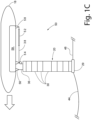
- FIG. 1C A schematic illustration of a representative the adjustment mechanism 50 for the dynamic foil system 20 is shown in greater detail in FIG. 1C .
- a turnbuckle 52 and a pulley 54, ratchet, winch, or similar cable guide and feed mechanism may be mounted to the floatation apparatus 18, e.g., between the top end of the aft control cable 38 and an aft anchor point 58 on the back or rear section of the floatation apparatus 18 (in the trailing edge direction of the foil sections 30).
- the forward cable 36 is mounted to a forward anchor 56 attached to the front section of the floatation apparatus 18 (in the leading edge direction of the foil sections 30).
- the adjustment mechanism 50 can be configured for adjusting either the forward cable 36 or the aft cable 38; both embodiments are encompassed. Another option is to use an adjustment mechanism 50 that provides differential adjustments to both forward and aft cabled 36, 38; e.g., by shortening one cable while lengthening the other at the same time. In some designs a single control cable may be used, extending from the forward cable anchor 56 down along a forward cable section 36, then passing through a cable return or wrapping or inflecting around a cable connector 29 attached to a submerged cable 44, and back up along an aft cable section 38 to the aft anchor 58 through the pulley 54.
- separate forward and aft control cables 36, 38 may be provided, e.g., individually attached at the submerged cable connector 29.
- the submerged cable 44 can be provided either as a tow line for a streamer cable 48 or as an umbilical for a source gun array.
- a control device 59 for the adjustment mechanism 50 may be located at either the top or bottom end of the foil system 20, for example, inside the floatation apparatus 18.
- Suitable control devices 59 include processor, memory, and software components configured to direct the adjustment mechanism 50 to selectively vary the length and/or tension in the forward and aft cables 36, 38, in order to regulate the lift and steering forces generated by the foil system 20 by changing the angle of attack along individual foil sections 30.
- the control device 59 may be configured to control an electric motor or similar drive in order to actuate the adjustment mechanism 50, providing for automated steering by adjustment of the relative length and tension in the forward and aft control cables 36, 38.
- Other control options include, but are not limited to, hydraulic and pneumatically controlled ram or piston mechanisms, electric winch drives, and motor-driven rack and pinion arrangements.
- a number of seismic energy source devices and/or a number of sensor nodes may be attached along the length of cables deployed and towed behind the marine vessel.
- Each of the cables, or the seismic equipment attached to the cables may have a steering device associated therewith in order to adjust the position of the cable or seismic devices within the water.
- a predetermined course e.g., in order to accurately map a subsurface formation.
- steering mechanisms may be attached to each cable and further or alternatively attached to the equipment towed by the cable.
- the foil systems 20 are just one exemplary implementation of a steering mechanism that may be employed to steer and position cables, seismic energy sources, sensor nodes, buoys and floats in the seismic array, etc.
- Other steering mechanisms for attachment to such sensor array components exist. These may include paravanes, hydrofoils, rudders, wings, elevators, and various other devices. The orientations of each of these devices while being towed through the water may be adjusted for steering. Such adjustments may be made by increasing or decreasing tension on control cables (i.e., making them more taught or more slack), engaging actuators to physically move a steering element; engaging motors to drive rotating elements, etc.
- the steering mechanisms are controlled by signals calculated to alter their orientation appropriately to maintain a proper course for the seismic array elements within the water. These signals are determined by sophisticated navigation and control systems that work in concert with the navigation of the marine vessel in order to ensure that the elements of the seismic array stay on course and maintain proper separation distances between adjacent elements.
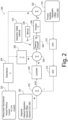
- FIG. 2 is a schematic diagram of an implementation of a control system 200 for use in steering towed marine equipment.
- a number of set points or control system input variable values may be defined and input into the control system 200 as a starting point as indicated by data input 202.
- set points may include desired separation distances between cables or other components of the steerable towed equipment, a desired offset or minimal offset from the plotted course of the center of the marine vessel towing the equipment, or a desired center-of-source/course-made-good (COS/CMG) identified as a center point of a towed seismic array.
- COS/CMG center-of-source/course-made-good
- the controller 204 may be any type of control module capable of incorporating feedback, for example, a state-variable controller, a proportional integral derivative (PID) controller, a multi-input/multi-output controller, etc.
- the controller 204 receives the input values for the course and calculates particular steering instructions that are translated into a specific control command for the particular steering mechanism attached to a cable or other marine equipment being towed.
- the steering instructions and control commands are specific to the type of steering mechanism being controlled, the type of towed equipment connected to the steering device, and the particular course that the towed equipment is intended to follow.
- the steering instructions generated by the controller 204 are then forwarded to a steering actuator 206.
- the steering actuator 206 may be any one of a number of devices used to control the orientation of or steering of towed marine equipment.
- the steering actuator 206 may be a switch to a motor driven propeller that is turned on and off and oriented in an appropriate direction to effect the steering command.
- the steering actuator 206 may be a mechanical device that orients a rudder, fin, or other hydrofoil in a certain direction to steer the associated cable or other marine equipment in a desired direction as the cable is pulled behind the vessel.
- the control system 200 may invoke a mathematical model to compute the anticipated results of the steering action as indicated by process module 208.
- the process (G) module 208 may compute as an output a process variable data set 210 of the same type as the set point variables 202.
- the process (G) module 208 may compute a modeled position and separation distance between elements of the towed equipment as expected in response to the prior steering input. Additionally or alternatively, an offset process variable may be computed to determine the likely actual course for the center of the vessel.
- the process (G) module 208 may calculate an anticipated COS/CMG position of a center of all towed equipment in an array behind the vessel after the steering command is implemented.
- Other process variables may similarly be calculated according to mathematical models programmed in the process (G) module 208.
- the values of the variables in the process variables data set 210 become the primary input into a feedback loop for the control system 200 in order to provide a basis for error correction.
- GPS global positioning satellite
- process variables data set 210 additional geographic positional information may be determined for use in error correction of course aberrations.
- GPS global positioning satellite
- the GPS information 212 and the process variables values 210 may be forwarded to a navigation system 214.
- the navigation system 214 uses the data from the GPS 212 and process variable information 210 to calculate an estimated geographic position of the towed marine equipment.
- the calculated estimated position may be compared to a pre-plotted course for the towed marine equipment within the navigation system 214.
- the calculated navigation information is then forwarded to an error calculator 216.
- the error calculator 216 also receives the original set point information and course information from the setpoint dataset 202 and computes a difference between the desired course and position of each of the towed marine equipment elements and the computed actual positions in process variable values output by the navigation system 214. If there is a difference between these values, an error is registered and the difference values are input in to the controller 204 for calculation of new control commands for the steering actuator 206 intended correct any differences between the planned course and the actual course. In this manner a feedback loop is created for error correction of the steering control of the towed marine equipment.
- control system 200 may also include a safety override.
- a separation safety interlock 218 may be connected with the steering actuator 206 in order to interrupt or deavtivate the steering actuator 206 in the event that two or more pieces of the towed marine equipment are determined to be too close together, in order to avoid a risk of entanglement between and potential damage to the towed marine equipment.
- a manual override module 220 may be provided within the control system 200 to allow manual control of the steering actuator 206.
- This portion of the control system 200 for use with steering towed marine equipment thus described provides steering control and error correction through a feedback loop.
- the control system 200 may not react quickly enough to changes in the environment or more significant course corrections of the marine vessel towing the marine equipment. Because of the slow reaction time of the feedback loop, it may take an excessive amount of time for the towed marine equipment to return to a pre-planned course position. In the context of conducting marine seismic surveys, source energy and sensing equipment that are substantially out of position can lead to poor survey results. For these reasons, a forward feedback control loop is further contemplated and implemented within the control system 200.
- a number of measurable disturbances that are separately notable and recordable may have significant impacts upon the course of a piece of steerable towed marine equipment.
- Such disturbances may include a significant change in the heading of the marine vessel towing the steerable towed marine equipment.
- Ocean currents can also create measurable effects on the course of the towed marine equipment as the equipment passes through the current.
- inline currents i.e., currents flowing in a parallel direction to the course of the towed equipment
- Crossline currents can push the towed marine equipment significantly off course either to starboard or to port.
- these and other kinds of disturbances may be known or noticed in advance of their imparting noticeable effect upon the steerable towed marine equipment.
- a vessel heading or speed changes e.g., to counteract currents or wind
- such information would be input into the marine vessel control system and may be made immediately available to each control system 200 for each of the steering actuators 206 for the steerable towed marine equipment.
- the marine vessel or the steerable towed equipment itself may include current sensors, for example, an acoustic Doppler profiler that measures the speed and direction of underwater currents which may have an effect on the steerable towed marine equipment.
- Such information can be collected and provided as an input into a forward feed control loop in the control system 200 as indicated by data set 222. This information may be provided as input variables to a mathematical model of disturbance (U) as indicated by disturbance module 224.
- U mathematical model of disturbance
- the disturbance module 224 may invoke preconfigured models to calculate the impact of any disturbance values on the process variables input into the feedback loop.
- models may be developed in advance, for example, through experimental trials and recordation of effects of changes in speed and heading of the vessel in response to wind and currents and the corresponding effects on sensor positions in a towed array.
- Artificial intelligence, neural networks, fuzzy logic, and other modeling techniques may be employed to build models responsive to various disturbance conditions encountered by or caused by vessels towing arrays in such trials.
- Output of the calculated disturbance values may be used as input for correction of control signals to the steering actuator 206 and as input within the feedback loop of the control system 200.
- a disturbance value may be used as an anticipatory action to immediately change the control input to the steering actuator 206.
- a quotient of a disturbance value (U) and the most recent process value (G) may be added to the output of the controller 204 by a correction calculator 228.
- a percentage or portion of the disturbance value (U) is thus used to immediately effect changes in the control signal to the steering actuator 206 to respond to measurable disturbances before the effects of the measurable disturbances are recognized in the standard feedback loop. This type of proactive correction thus helps better maintain the desired position of the steerable towed equipment.
- calculated disturbance values (U) may be output to enter the feedback loop and be added to corresponding calculated process values (G) by a feedback correction calculator 230. In this manner the effect of measurable disturbances is taken into account into the feedback loop to help more accurately calculate the navigational position of the steerable towed marine equipment.
- input values provided to the controller 204 may generate commands to the steering actuator 206 that will result in more stable and accurate steering and positioning of the steerable towed marine equipment.
- the computer system 300 may be a personal computer (PC), a workstation, a server, a mainframe computer, a distributed computer a portable notebook or tablet computer, or functionally distributed across a number of computers and pieces of specialized control equipment (e.g., the controller 204 and the navigation module 214), each with internal processing and memory components as well as interface components for connection with external input, output, storage, network, and other types of peripheral devices.
- the computer system 300 of FIG. 3 is intended to be a generic representation of computers and control equipment that may include some or all of the components depicted and described. Internal components of the computer system in FIG. 3 are shown within the dashed line and external components are shown outside of the dashed line. Components that may be internal or external are shown straddling the dashed line.
- the computer system 300 includes a processor 302 and a system memory 306 connected by a system bus 304 that also operatively couples various system components.
- processors 302 e.g., a single central processing unit (CPU), or a plurality of processing units, commonly referred to as a parallel processing environment (for example, a dual-core, quad-core, or other multi-core processing device).
- the system bus 304 may be any of several types of bus structures including a memory bus or memory controller, a peripheral bus, a switched-fabric, point-to-point connection, and a local bus using any of a variety of bus architectures.
- the system memory 306 includes read only memory (ROM) 308 and random access memory (RAM) 310.
- ROM read only memory
- RAM random access memory
- BIOS basic input/output system
- a cache 314 may be set aside in RAM 310 to provide a high speed memory store for frequently accessed data.
- a hard disk drive interface 316 may be connected with the system bus 304 to provide read and write access to a data storage device, e.g., a hard disk drive 318, for nonvolatile storage of applications, files, and data.
- a data storage device e.g., a hard disk drive 318
- a number of program modules and other data may be stored on the hard disk 318, including an operating system 320, one or more application programs 322, and data files 324 (for example, the setpoint values and the process values).
- the hard disk drive 318 may store the process calculation module 364, the disturbance calculation module 366, and any number of error correction calculators 326.
- the hard disk drive 318 may be either an internal component or an external component of the computer system 300 as indicated by the hard disk drive 318 straddling the dashed line in FIG. 3 . In some configurations, there may be both an internal and an external hard disk drive 318.
- the computer system 300 may further include a magnetic disk drive 330 for reading from or writing to a removable magnetic disk 332, tape, or other magnetic media.
- the magnetic disk drive 330 may be connected with the system bus 304 via a magnetic drive interface 328 to provide read and write access to the magnetic disk drive 330 initiated by other components or applications within the computer system 300.
- the magnetic disk drive 330 and the associated computer-readable media may be used to provide nonvolatile storage of computer-readable instructions, data structures, program modules, and other data for the computer system 300.
- the computer system 300 may additionally include an optical disk drive 336 for reading from or writing to a removable optical disk 338 such as a CD ROM or other optical media.
- the optical disk drive 336 may be connected with the system bus 304 via an optical drive interface 334 to provide read and write access to the optical disk drive 336 initiated by other components or applications within the computer system 300.
- the optical disk drive 330 and the associated computer-readable optical media may be used to provide nonvolatile storage of computer-readable instructions, data structures, program modules, and other data for the computer system 300.
- a display device 342 e.g., a monitor, a television, or a projector, or other type of presentation device may also be connected to the system bus 304 via an interface, such as a video adapter 340 or video card.
- audio devices for example, external speakers or a microphone (not shown), may be connected to the system bus 304 through an audio card or other audio interface (not shown).
- the computer system 300 may include other peripheral input and output devices, which are often connected to the processor 302 and memory 306 through the serial port interface 344 that is coupled to the system bus 306.
- Input and output devices may also or alternately be connected with the system bus 304 by other interfaces, for example, a universal serial bus (USB), an IEEE 1394 interface (“Firewire”), a parallel port, or any number of input/output hardware configurations and protocols.
- USB universal serial bus
- IEEE 1394 interface IEEE 1394 interface
- parallel port a parallel port
- a user may enter commands and information into the computer system 300 through various input devices including, for example, a keyboard 346 and pointing device 348, for example, a computer mouse.
- Other input devices may include, for example, a joystick, a game pad, a tablet, a touch screen device, a satellite dish, a scanner, antennae, GPS devices, a facsimile machine, a microphone, a digital camera, and a digital video camera.
- Other output devices may include a printer 350 and one or more loudspeakers 370 for presenting the audio performance of the sender.
- Further output devices may include, for example, a plotter, a photocopier, a photo printer, a facsimile machine, and a press. In some implementations, several of these input and output devices may be combined into single devices, for example, a printer/scanner/fax/photocopier.
- other types of computer-readable media and associated drives for storing data for example, magnetic cassettes or flash memory drives, may be accessed by the computer system 300 via the serial port interface 344 (e.g., USB) or similar port interface.
- the computer system 300 may operate in a networked environment using logical connections through a network interface 352 coupled with the system bus 304 to communicate with one or more remote devices.
- the logical connections depicted in FIG. 3 include a local-area network (LAN) 354 and a wide-area network (WAN) 360. These logical connections may be achieved by a communication device coupled to or integral with the computer system 300.
- the LAN 354 may use a router 356 or hub, either wired or wireless, internal or external, to connect with remote devices, e.g., a remote computer 358, similarly connected on the LAN 354.
- the remote computer 358 may be another personal computer, a server, a client, a peer device, or other common network node, and typically includes many or all of the elements described above relative to the computer system 300.
- each of the sensor nodes may be configured to wirelessly connect with the LAN 354 upon retrieval from deployment to download collected data for storage and processing.
- the computer system 300 typically includes a modem 362 for establishing communications over the WAN 360.
- the WAN 360 may be the Internet.
- the WAN 360 may be a large private network spread among multiple locations, or a virtual private network (VPN).
- the modem 362 may be a telephone modem, a high speed modem (e.g., a digital subscriber line (DSL) modem), a cable modem, a satellite modem, or similar type of communications device.
- the modem 362, which may be internal or external, is connected to the system bus 318 via the network interface 352. In alternate embodiments the modem 362 may be connected via the serial port interface 344.
- the network connections shown are exemplary and other means of and communications devices for establishing a network communications link between the computer system and other devices or networks may be used.
- the technology described herein may be implemented as logical operations and/or modules in one or more systems.
- the logical operations may be implemented as a sequence of processor-implemented steps executing in one or more computer systems and as interconnected machine or circuit modules within one or more computer systems.
- the descriptions of various component modules may be provided in terms of operations executed or effected by the modules.
- the resulting implementation is a matter of choice, dependent on the performance requirements of the underlying system implementing the described technology.
- the logical operations making up the embodiments of the technology described herein are referred to variously as operations, steps, objects, or modules.
- logical operations may be performed in any order, unless explicitly claimed otherwise or a specific order is inherently necessitated by the claim language.
- articles of manufacture are provided as computer program products that cause the instantiation of operations on a computer system to implement the procedural operations.
- One implementation of a computer program product provides a non-transitory computer program storage medium readable by a computer system and encoding a computer program. It should further be understood that the described technology may be employed in special purpose devices independent of a personal computer.
Landscapes
- Engineering & Computer Science (AREA)
- Life Sciences & Earth Sciences (AREA)
- Physics & Mathematics (AREA)
- Remote Sensing (AREA)
- Combustion & Propulsion (AREA)
- Mechanical Engineering (AREA)
- Ocean & Marine Engineering (AREA)
- Chemical & Material Sciences (AREA)
- General Physics & Mathematics (AREA)
- Radar, Positioning & Navigation (AREA)
- Geology (AREA)
- Environmental & Geological Engineering (AREA)
- General Life Sciences & Earth Sciences (AREA)
- Acoustics & Sound (AREA)
- Geophysics (AREA)
- Oceanography (AREA)
- Aviation & Aerospace Engineering (AREA)
- Automation & Control Theory (AREA)
- Position Fixing By Use Of Radio Waves (AREA)
- Control Of Position, Course, Altitude, Or Attitude Of Moving Bodies (AREA)
- Guiding Agricultural Machines (AREA)
Claims (11)
- Système de commande d'un actionneur de guidage (200) pour fournir des ordres de commande de guidage à un actionneur de guidage (206) d'un dispositif de guidage (20) sur une partie d'un équipement marin tracté (70), l'équipement marin tracté (70) étant composé de plusieurs parties,système de commande (200) comprenant :- une mémoire (202) contenant des données de point fixé comprenant des valeurs de position pour une position souhaitée pour chaque partie de l'équipement marin tracté (70) et,système de commande (200) caractérisé en ce qu'il comprend :- un modèle de calcul de données de procédé (208) pour appliquer un premier modèle mathématique pour calculer des données de procédé représentant la position actuelle calculée de chaque partie de l'équipement marin tracté en réponse à une commande d'un ordre de commande de guidage antérieur,- un module de commande (204) configuré pour* recevoir des données de point fixé,* recevoir des données de procédé représentant la position actuelle calculée de chaque partie de l'équipement marin tracté (70),* calculer la différence entre les données de point fixé, reçues et les données de procédé reçues ; et* calculer un ordre de commande de l'actionneur de guidage (206) de la partie guidée (20) s'il y a une différence entre la donnée de point fixé et la donnée de procédé ;- un module de calcul de réglage de dérangement (226) pour combiner une valeur de dérangement, fondée sur un dérangement mesuré avec une valeur de données de procédé et fournir en sortie une valeur de réglage de dérangement,* la valeur de réglage de dérangement étant le quotient de la valeur de dérangement au numérateur et de la valeur de la donnée de procédé au dénominateur ; et- un module de calculateur de correction (228) qui ajoute la valeur de réglage de dérangement à l'ordre de commande pour créer un ordre de commande ajusté pour être transmis à l'actionneur de guidage (206).
- Système de commande (200) selon la revendication 1,
comprenant en outre
un calculateur de réglage de retour de dérangement (230) pour ajouter la valeur de réglage de dérangement à la donnée de procédé pour régler la donnée de procédé comme entrée dans une boucle de réaction fournissant une donnée supplémentaire au module de commande (204). - Système de commande (200) selon la revendication 1,
dans lequel
le module de calcul de données de procédé (208) est configuré pour appliquer le premier modèle mathématique au calcul de la position actuelle, calculée, de chaque partie de l'équipement marin tracté (70) en se fondant sur la donnée de position géographique et l'ordre de commande ajusté. - Système de commande (200) selon la revendication 1,
comprenant en outre
un module de calcul de données de dérangement (224) configuré pour :- recevoir une information de dérangement mesuré,- calculer l'impact de l'information de dérangement mesuré sur la course de la partie de l'équipement marin tracté (70) et/ou sur un ou plusieurs composants de la partie d'équipement marin tracté (70) en appliquant un second modèle mathématique et- fournir en sortie, la valeur de dérangement représentant l'impact de l'information de dérangement. - Système de commande (200) selon la revendication 1,
comprenant en outre
un récepteur de satellite de positionnement global (GPS) pour fournir une information de position GPS à un système de navigation (214) utilisé pour déterminer la position géographique. - Système de commande (200) selon la revendication 1,
selon lequel
la mesure de dérangement comprend un ou plusieurs des éléments suivants :- une entête de vaisseau (12) tractant la partie de l'équipement marin tracté (70) et/ou un ou plusieurs composants de la partie de l'équipement marin tracté (70),- une vitesse de vaisseau (12) tractant la partie de l'équipement marin tracté (70) et/ou d'un ou plusieurs composants de la partie de l'équipement marin tracté (70), - une vitesse d'un courant influençant le vaisseau (12), la partie de l'équipement marin tracté (70) et/ou un ou plusieurs composants de la partie de l'équipement marin tracté (70) dans l'eau dans laquelle sont déployés le vaisseau (12) et la partie de l'équipement marin tracté (70) ; ou- la direction d'un courant appliquée au vaisseau (12) ou à la partie de l'équipement marin tracté (70) et/ou à un ou plusieurs composants de la partie de l'équipement marin tracté (70) dans l'eau dans laquelle sont déployés le vaisseau (12) et la partie de l'équipement marin tracté (70). - Procédé d'un système de commande actionneur de guidage (200) configuré pour fournir des ordres de commande de guidage à un actionneur de guidage (206) d'un dispositif de guidage (20) sur une partie d'un équipement marin tracté (70),cet équipement marin tracté (70) étant formé d'un ensemble de parties, procédé consistant à :- accéder aux données de point fixé comprenant les valeurs de position pour une position souhaitée pour chaque partie de l'équipement marin tracté (70) enregistrées dans une mémoire (202) d'un système de commande (200), etProcédé caractérisé en ce qu'il consiste à :- recevoir des données de procédé calculées par un premier modèle mathématique enregistré dans le système de commande (200), la donnée de procédé représentant une position actuelle calculée de chaque partie de l'équipement marin tracté (70) en réponse à un ordre de guidage antérieur ;- calculer la différence entre la donnée de point fixé, reçue et la donnée de procédé reçue ;- calculer un ordre de commande de l'actionneur de guidage (206) du dispositif de guidage (20) s'il y a une différence entre la donnée de point fixé et la donnée de procédé dans un module de commande (204) ;- combiner une valeur de dérangement d'un dérangement mesuré par une valeur de la données de procédé pour calculer une valeur de réglage de dérangement,* la valeur de réglage de dérangement étant le quotient de la valeur de dérangement au numérateur et de la valeur de données de procédé au dénominateur ;- ajouter la valeur de réglage de dérangement à l'ordre de commande pour obtenir un ordre de commande ajusté et ;- transmettre l'ordre de commande ajusté à l'actionneur de guidage (206).
- Procédé selon la revendication 7,
consistant en outre à :
ajouter la valeur de réglage de dérangement à la donnée de procédé pour ajuster la donnée de procédé pour être appliquée à une boucle de réaction fournissant une donnée supplémentaire au module de commande (204). - Procédé selon la revendication 7,
consistant en outre à:- calculer avec le premier modèle mathématique enregistré dans le système de commande (200), la position actuelle calculée de chaque partie de l'équipement marin tracté 70) en s'appuyant sur la donnée de position géographique et sur l'ordre de commande ajusté. - Procédé selon la revendication 7,
consistant en outre à:- calculer l'impact du dérangement mesuré sur la course de la partie d'équipement marin tracté (70) et/ou sur un ou plusieurs composants de chaque partie de l'équipement marin tracté (70) en appliquant un second modèle mathématique ; et- fournir en sortie la valeur de dérangement représentative de l'impact de l'information de dérangement mesuré. - Procédé selon la revendication 7,
selon lequel
le dérangement mesuré comprend un ou plusieurs des éléments suivants :- l'entête d'un vaisseau (12) tractant la partie d'équipement marin tracté (70) et/ou un ou plusieurs composants de la partie de l'équipement marin tracté (70) ;- la vitesse du vaisseau (12) tractant la partie d'équipement marin tracté (70) et/ou un ou plusieurs composants de la partie d'équipement marin tracté (70) ;- la vitesse du courant influençant le vaisseau (12), la partie d'équipement marin tracté (70) et/ou un ou plusieurs composants de la partie d'équipement marin tracté (70) dans l'eau dans laquelle sont déployés le vaisseau (12) et la partie de l'équipement marin tracté (70), ou- la direction d'un courant influençant le vaisseau (12), la partie d'équipement marin tracté (70) et/ou un ou plusieurs composants de la partie d'équipement marin tracté (70) dans l'eau dans laquelle sont déployés le vaisseau (12) et la partie de l'équipement marin tracté (70).
Applications Claiming Priority (2)
| Application Number | Priority Date | Filing Date | Title |
|---|---|---|---|
| US201862683007P | 2018-06-10 | 2018-06-10 | |
| PCT/US2019/036408 WO2019241164A1 (fr) | 2018-06-10 | 2019-06-10 | Système de commande pour équipement marin remorqué dirigeable |
Publications (2)
| Publication Number | Publication Date |
|---|---|
| EP3803473A1 EP3803473A1 (fr) | 2021-04-14 |
| EP3803473B1 true EP3803473B1 (fr) | 2024-09-25 |
Family
ID=67003787
Family Applications (1)
| Application Number | Title | Priority Date | Filing Date |
|---|---|---|---|
| EP19733383.4A Active EP3803473B1 (fr) | 2018-06-10 | 2019-06-10 | Système de commande pour équipement marin remorqué dirigeable |
Country Status (6)
| Country | Link |
|---|---|
| US (1) | US11940796B2 (fr) |
| EP (1) | EP3803473B1 (fr) |
| CA (1) | CA3100355A1 (fr) |
| DK (1) | DK3803473T3 (fr) |
| MX (1) | MX2020012779A (fr) |
| WO (1) | WO2019241164A1 (fr) |
Families Citing this family (5)
| Publication number | Priority date | Publication date | Assignee | Title |
|---|---|---|---|---|
| CA3100355A1 (fr) | 2018-06-10 | 2019-12-19 | Ion Geophysical Corporation | Systeme de commande pour equipement marin remorque dirigeable |
| US11048003B2 (en) * | 2018-12-18 | 2021-06-29 | Pgs Geophysical As | Bridle bite adjustment |
| NO345686B1 (en) * | 2020-03-11 | 2021-06-14 | Polarcus Shipholding As | Steering of marine equipment towed by a vessel by float with wings |
| US12043356B2 (en) * | 2020-08-07 | 2024-07-23 | Digicourse, Llc | Control system for steerable towed marine equipment |
| EP4036610A1 (fr) | 2021-01-29 | 2022-08-03 | Sercel | Procédé pour diriger un navire, système de navigation associé et procédé d'acquisition de données sismiques |
Family Cites Families (8)
| Publication number | Priority date | Publication date | Assignee | Title |
|---|---|---|---|---|
| US6691038B2 (en) * | 2001-06-15 | 2004-02-10 | Westerngeco L.L.C. | Active separation tracking and positioning system for towed seismic arrays |
| EP2793059A3 (fr) | 2004-03-17 | 2014-11-26 | WesternGeco Seismic Holdings Limited | Procédé et système d'étude sismique marine |
| US8391102B2 (en) | 2005-08-26 | 2013-03-05 | Westerngeco L.L.C. | Automatic systems and methods for positioning marine seismic equipment |
| US8483008B2 (en) | 2008-11-08 | 2013-07-09 | Westerngeco L.L.C. | Coil shooting mode |
| CA2856316C (fr) | 2011-10-28 | 2020-07-28 | Global Dynamics Incorporated | Cable carene dirigeable |
| NO338421B1 (no) | 2014-07-03 | 2016-08-15 | Kongsberg Seatex As | Fremgangsmåte og system for dynamisk posisjonering av instrumentert tauet kabel i vann |
| US10488541B2 (en) | 2015-10-15 | 2019-11-26 | Ion Geophysical Corporation | Dynamically controlled foil systems and methods |
| CA3100355A1 (fr) | 2018-06-10 | 2019-12-19 | Ion Geophysical Corporation | Systeme de commande pour equipement marin remorque dirigeable |
-
2019
- 2019-06-10 CA CA3100355A patent/CA3100355A1/fr active Pending
- 2019-06-10 DK DK19733383.4T patent/DK3803473T3/da active
- 2019-06-10 WO PCT/US2019/036408 patent/WO2019241164A1/fr not_active Ceased
- 2019-06-10 US US16/436,780 patent/US11940796B2/en active Active
- 2019-06-10 MX MX2020012779A patent/MX2020012779A/es unknown
- 2019-06-10 EP EP19733383.4A patent/EP3803473B1/fr active Active
Also Published As
| Publication number | Publication date |
|---|---|
| MX2020012779A (es) | 2021-02-15 |
| US11940796B2 (en) | 2024-03-26 |
| DK3803473T3 (da) | 2024-10-28 |
| US20190377348A1 (en) | 2019-12-12 |
| CA3100355A1 (fr) | 2019-12-19 |
| EP3803473A1 (fr) | 2021-04-14 |
| WO2019241164A1 (fr) | 2019-12-19 |
Similar Documents
| Publication | Publication Date | Title |
|---|---|---|
| US11940796B2 (en) | Control system for steerable towed marine equipment | |
| US10488541B2 (en) | Dynamically controlled foil systems and methods | |
| US7450467B2 (en) | Apparatus and methods for seismic streamer positioning | |
| US8483008B2 (en) | Coil shooting mode | |
| US7167412B2 (en) | Apparatus for steering a marine seismic streamer via controlled bending | |
| US6590831B1 (en) | Method and apparatus for controlling and optimizing seismic data acquisition | |
| US7203130B1 (en) | Methods for deriving shape of seismic data acquisition cables and streamers employing a force model | |
| US7933163B2 (en) | Method and system for controlling the position of marine seismic streamers | |
| AU2006203075B2 (en) | Automatic systems and methods for positioning marine seismic equipment | |
| US11077920B2 (en) | Modular foil system for towed marine array | |
| CA2801294C (fr) | Procede de deploiement, procede et dispositif de prospection sismique en milieu aquatique | |
| CN106471394B (zh) | 拖曳在水中的装备有仪器的缆线的动态定位方法和系统 | |
| US12043356B2 (en) | Control system for steerable towed marine equipment | |
| US20060133200A1 (en) | Apparatus for steering a marine seismic streamer via controlled water ejection | |
| EP1879053B1 (fr) | Procédé et système de contrôle de la position des flûtes sismiques marines |
Legal Events
| Date | Code | Title | Description |
|---|---|---|---|
| STAA | Information on the status of an ep patent application or granted ep patent |
Free format text: STATUS: UNKNOWN |
|
| STAA | Information on the status of an ep patent application or granted ep patent |
Free format text: STATUS: THE INTERNATIONAL PUBLICATION HAS BEEN MADE |
|
| PUAI | Public reference made under article 153(3) epc to a published international application that has entered the european phase |
Free format text: ORIGINAL CODE: 0009012 |
|
| STAA | Information on the status of an ep patent application or granted ep patent |
Free format text: STATUS: REQUEST FOR EXAMINATION WAS MADE |
|
| 17P | Request for examination filed |
Effective date: 20210111 |
|
| AK | Designated contracting states |
Kind code of ref document: A1 Designated state(s): AL AT BE BG CH CY CZ DE DK EE ES FI FR GB GR HR HU IE IS IT LI LT LU LV MC MK MT NL NO PL PT RO RS SE SI SK SM TR |
|
| AX | Request for extension of the european patent |
Extension state: BA ME |
|
| DAV | Request for validation of the european patent (deleted) | ||
| DAX | Request for extension of the european patent (deleted) | ||
| STAA | Information on the status of an ep patent application or granted ep patent |
Free format text: STATUS: EXAMINATION IS IN PROGRESS |
|
| 17Q | First examination report despatched |
Effective date: 20221215 |
|
| RAP1 | Party data changed (applicant data changed or rights of an application transferred) |
Owner name: DIGICOURSE LLC |
|
| GRAP | Despatch of communication of intention to grant a patent |
Free format text: ORIGINAL CODE: EPIDOSNIGR1 |
|
| STAA | Information on the status of an ep patent application or granted ep patent |
Free format text: STATUS: GRANT OF PATENT IS INTENDED |
|
| INTG | Intention to grant announced |
Effective date: 20240704 |
|
| GRAS | Grant fee paid |
Free format text: ORIGINAL CODE: EPIDOSNIGR3 |
|
| GRAA | (expected) grant |
Free format text: ORIGINAL CODE: 0009210 |
|
| STAA | Information on the status of an ep patent application or granted ep patent |
Free format text: STATUS: THE PATENT HAS BEEN GRANTED |
|
| P01 | Opt-out of the competence of the unified patent court (upc) registered |
Free format text: CASE NUMBER: APP_46894/2024 Effective date: 20240813 |
|
| AK | Designated contracting states |
Kind code of ref document: B1 Designated state(s): AL AT BE BG CH CY CZ DE DK EE ES FI FR GB GR HR HU IE IS IT LI LT LU LV MC MK MT NL NO PL PT RO RS SE SI SK SM TR |
|
| REG | Reference to a national code |
Ref country code: GB Ref legal event code: FG4D |
|
| REG | Reference to a national code |
Ref country code: CH Ref legal event code: EP |
|
| REG | Reference to a national code |
Ref country code: DE Ref legal event code: R096 Ref document number: 602019059422 Country of ref document: DE |
|
| REG | Reference to a national code |
Ref country code: IE Ref legal event code: FG4D |
|
| REG | Reference to a national code |
Ref country code: DK Ref legal event code: T3 Effective date: 20241023 |
|
| REG | Reference to a national code |
Ref country code: LT Ref legal event code: MG9D |
|
| PG25 | Lapsed in a contracting state [announced via postgrant information from national office to epo] |
Ref country code: GR Free format text: LAPSE BECAUSE OF FAILURE TO SUBMIT A TRANSLATION OF THE DESCRIPTION OR TO PAY THE FEE WITHIN THE PRESCRIBED TIME-LIMIT Effective date: 20241226 Ref country code: FI Free format text: LAPSE BECAUSE OF FAILURE TO SUBMIT A TRANSLATION OF THE DESCRIPTION OR TO PAY THE FEE WITHIN THE PRESCRIBED TIME-LIMIT Effective date: 20240925 |
|
| PG25 | Lapsed in a contracting state [announced via postgrant information from national office to epo] |
Ref country code: BG Free format text: LAPSE BECAUSE OF FAILURE TO SUBMIT A TRANSLATION OF THE DESCRIPTION OR TO PAY THE FEE WITHIN THE PRESCRIBED TIME-LIMIT Effective date: 20240925 |
|
| PG25 | Lapsed in a contracting state [announced via postgrant information from national office to epo] |
Ref country code: LV Free format text: LAPSE BECAUSE OF FAILURE TO SUBMIT A TRANSLATION OF THE DESCRIPTION OR TO PAY THE FEE WITHIN THE PRESCRIBED TIME-LIMIT Effective date: 20240925 |
|
| PG25 | Lapsed in a contracting state [announced via postgrant information from national office to epo] |
Ref country code: RS Free format text: LAPSE BECAUSE OF FAILURE TO SUBMIT A TRANSLATION OF THE DESCRIPTION OR TO PAY THE FEE WITHIN THE PRESCRIBED TIME-LIMIT Effective date: 20241225 |
|
| REG | Reference to a national code |
Ref country code: NL Ref legal event code: MP Effective date: 20240925 |
|
| PG25 | Lapsed in a contracting state [announced via postgrant information from national office to epo] |
Ref country code: RS Free format text: LAPSE BECAUSE OF FAILURE TO SUBMIT A TRANSLATION OF THE DESCRIPTION OR TO PAY THE FEE WITHIN THE PRESCRIBED TIME-LIMIT Effective date: 20241225 Ref country code: LV Free format text: LAPSE BECAUSE OF FAILURE TO SUBMIT A TRANSLATION OF THE DESCRIPTION OR TO PAY THE FEE WITHIN THE PRESCRIBED TIME-LIMIT Effective date: 20240925 Ref country code: GR Free format text: LAPSE BECAUSE OF FAILURE TO SUBMIT A TRANSLATION OF THE DESCRIPTION OR TO PAY THE FEE WITHIN THE PRESCRIBED TIME-LIMIT Effective date: 20241226 Ref country code: FI Free format text: LAPSE BECAUSE OF FAILURE TO SUBMIT A TRANSLATION OF THE DESCRIPTION OR TO PAY THE FEE WITHIN THE PRESCRIBED TIME-LIMIT Effective date: 20240925 Ref country code: BG Free format text: LAPSE BECAUSE OF FAILURE TO SUBMIT A TRANSLATION OF THE DESCRIPTION OR TO PAY THE FEE WITHIN THE PRESCRIBED TIME-LIMIT Effective date: 20240925 |
|
| REG | Reference to a national code |
Ref country code: AT Ref legal event code: MK05 Ref document number: 1727093 Country of ref document: AT Kind code of ref document: T Effective date: 20240925 |
|
| PG25 | Lapsed in a contracting state [announced via postgrant information from national office to epo] |
Ref country code: NL Free format text: LAPSE BECAUSE OF FAILURE TO SUBMIT A TRANSLATION OF THE DESCRIPTION OR TO PAY THE FEE WITHIN THE PRESCRIBED TIME-LIMIT Effective date: 20240925 |
|
| PG25 | Lapsed in a contracting state [announced via postgrant information from national office to epo] |
Ref country code: PT Free format text: LAPSE BECAUSE OF FAILURE TO SUBMIT A TRANSLATION OF THE DESCRIPTION OR TO PAY THE FEE WITHIN THE PRESCRIBED TIME-LIMIT Effective date: 20250127 Ref country code: IS Free format text: LAPSE BECAUSE OF FAILURE TO SUBMIT A TRANSLATION OF THE DESCRIPTION OR TO PAY THE FEE WITHIN THE PRESCRIBED TIME-LIMIT Effective date: 20250125 |
|
| PG25 | Lapsed in a contracting state [announced via postgrant information from national office to epo] |
Ref country code: RO Free format text: LAPSE BECAUSE OF FAILURE TO SUBMIT A TRANSLATION OF THE DESCRIPTION OR TO PAY THE FEE WITHIN THE PRESCRIBED TIME-LIMIT Effective date: 20240925 Ref country code: SM Free format text: LAPSE BECAUSE OF FAILURE TO SUBMIT A TRANSLATION OF THE DESCRIPTION OR TO PAY THE FEE WITHIN THE PRESCRIBED TIME-LIMIT Effective date: 20240925 |
|
| PG25 | Lapsed in a contracting state [announced via postgrant information from national office to epo] |
Ref country code: ES Free format text: LAPSE BECAUSE OF FAILURE TO SUBMIT A TRANSLATION OF THE DESCRIPTION OR TO PAY THE FEE WITHIN THE PRESCRIBED TIME-LIMIT Effective date: 20240925 |
|
| PG25 | Lapsed in a contracting state [announced via postgrant information from national office to epo] |
Ref country code: EE Free format text: LAPSE BECAUSE OF FAILURE TO SUBMIT A TRANSLATION OF THE DESCRIPTION OR TO PAY THE FEE WITHIN THE PRESCRIBED TIME-LIMIT Effective date: 20240925 Ref country code: AT Free format text: LAPSE BECAUSE OF FAILURE TO SUBMIT A TRANSLATION OF THE DESCRIPTION OR TO PAY THE FEE WITHIN THE PRESCRIBED TIME-LIMIT Effective date: 20240925 |
|
| PG25 | Lapsed in a contracting state [announced via postgrant information from national office to epo] |
Ref country code: CZ Free format text: LAPSE BECAUSE OF FAILURE TO SUBMIT A TRANSLATION OF THE DESCRIPTION OR TO PAY THE FEE WITHIN THE PRESCRIBED TIME-LIMIT Effective date: 20240925 Ref country code: PL Free format text: LAPSE BECAUSE OF FAILURE TO SUBMIT A TRANSLATION OF THE DESCRIPTION OR TO PAY THE FEE WITHIN THE PRESCRIBED TIME-LIMIT Effective date: 20240925 |
|
| PG25 | Lapsed in a contracting state [announced via postgrant information from national office to epo] |
Ref country code: IT Free format text: LAPSE BECAUSE OF FAILURE TO SUBMIT A TRANSLATION OF THE DESCRIPTION OR TO PAY THE FEE WITHIN THE PRESCRIBED TIME-LIMIT Effective date: 20240925 Ref country code: SK Free format text: LAPSE BECAUSE OF FAILURE TO SUBMIT A TRANSLATION OF THE DESCRIPTION OR TO PAY THE FEE WITHIN THE PRESCRIBED TIME-LIMIT Effective date: 20240925 |
|
| REG | Reference to a national code |
Ref country code: DE Ref legal event code: R097 Ref document number: 602019059422 Country of ref document: DE |
|
| PGFP | Annual fee paid to national office [announced via postgrant information from national office to epo] |
Ref country code: DE Payment date: 20250618 Year of fee payment: 7 |
|
| PGFP | Annual fee paid to national office [announced via postgrant information from national office to epo] |
Ref country code: GB Payment date: 20250617 Year of fee payment: 7 Ref country code: DK Payment date: 20250625 Year of fee payment: 7 |
|
| PGFP | Annual fee paid to national office [announced via postgrant information from national office to epo] |
Ref country code: NO Payment date: 20250624 Year of fee payment: 7 |
|
| PGFP | Annual fee paid to national office [announced via postgrant information from national office to epo] |
Ref country code: FR Payment date: 20250626 Year of fee payment: 7 |
|
| PLBE | No opposition filed within time limit |
Free format text: ORIGINAL CODE: 0009261 |
|
| STAA | Information on the status of an ep patent application or granted ep patent |
Free format text: STATUS: NO OPPOSITION FILED WITHIN TIME LIMIT |
|
| 26N | No opposition filed |
Effective date: 20250626 |
|
| PG25 | Lapsed in a contracting state [announced via postgrant information from national office to epo] |
Ref country code: SE Free format text: LAPSE BECAUSE OF FAILURE TO SUBMIT A TRANSLATION OF THE DESCRIPTION OR TO PAY THE FEE WITHIN THE PRESCRIBED TIME-LIMIT Effective date: 20240925 |
|
| PG25 | Lapsed in a contracting state [announced via postgrant information from national office to epo] |
Ref country code: HR Free format text: LAPSE BECAUSE OF FAILURE TO SUBMIT A TRANSLATION OF THE DESCRIPTION OR TO PAY THE FEE WITHIN THE PRESCRIBED TIME-LIMIT Effective date: 20240925 |
|
| REG | Reference to a national code |
Ref country code: CH Ref legal event code: H13 Free format text: ST27 STATUS EVENT CODE: U-0-0-H10-H13 (AS PROVIDED BY THE NATIONAL OFFICE) Effective date: 20260127 |
|
| PG25 | Lapsed in a contracting state [announced via postgrant information from national office to epo] |
Ref country code: MC Free format text: LAPSE BECAUSE OF FAILURE TO SUBMIT A TRANSLATION OF THE DESCRIPTION OR TO PAY THE FEE WITHIN THE PRESCRIBED TIME-LIMIT Effective date: 20240925 |
|
| PG25 | Lapsed in a contracting state [announced via postgrant information from national office to epo] |
Ref country code: LU Free format text: LAPSE BECAUSE OF NON-PAYMENT OF DUE FEES Effective date: 20250610 |
|
| REG | Reference to a national code |
Ref country code: BE Ref legal event code: MM Effective date: 20250630 |
|
| PG25 | Lapsed in a contracting state [announced via postgrant information from national office to epo] |
Ref country code: IE Free format text: LAPSE BECAUSE OF NON-PAYMENT OF DUE FEES Effective date: 20250610 |
|
| PG25 | Lapsed in a contracting state [announced via postgrant information from national office to epo] |
Ref country code: BE Free format text: LAPSE BECAUSE OF NON-PAYMENT OF DUE FEES Effective date: 20250630 |
|
| PG25 | Lapsed in a contracting state [announced via postgrant information from national office to epo] |
Ref country code: CH Free format text: LAPSE BECAUSE OF NON-PAYMENT OF DUE FEES Effective date: 20250630 |