EP3805636A1 - Positionnement d'un corps de lentille silicone sur une del - Google Patents
Positionnement d'un corps de lentille silicone sur une del Download PDFInfo
- Publication number
- EP3805636A1 EP3805636A1 EP20200321.6A EP20200321A EP3805636A1 EP 3805636 A1 EP3805636 A1 EP 3805636A1 EP 20200321 A EP20200321 A EP 20200321A EP 3805636 A1 EP3805636 A1 EP 3805636A1
- Authority
- EP
- European Patent Office
- Prior art keywords
- led
- lens body
- lighting device
- cover
- circuit board
- Prior art date
- Legal status (The legal status is an assumption and is not a legal conclusion. Google has not performed a legal analysis and makes no representation as to the accuracy of the status listed.)
- Granted
Links
Images


Classifications
-
- F—MECHANICAL ENGINEERING; LIGHTING; HEATING; WEAPONS; BLASTING
- F21—LIGHTING
- F21V—FUNCTIONAL FEATURES OR DETAILS OF LIGHTING DEVICES OR SYSTEMS THEREOF; STRUCTURAL COMBINATIONS OF LIGHTING DEVICES WITH OTHER ARTICLES, NOT OTHERWISE PROVIDED FOR
- F21V3/00—Globes; Bowls; Cover glasses
- F21V3/02—Globes; Bowls; Cover glasses characterised by the shape
-
- F—MECHANICAL ENGINEERING; LIGHTING; HEATING; WEAPONS; BLASTING
- F21—LIGHTING
- F21V—FUNCTIONAL FEATURES OR DETAILS OF LIGHTING DEVICES OR SYSTEMS THEREOF; STRUCTURAL COMBINATIONS OF LIGHTING DEVICES WITH OTHER ARTICLES, NOT OTHERWISE PROVIDED FOR
- F21V17/00—Fastening of component parts of lighting devices, e.g. shades, globes, refractors, reflectors, filters, screens, grids or protective cages
- F21V17/005—Fastening of component parts of lighting devices, e.g. shades, globes, refractors, reflectors, filters, screens, grids or protective cages with keying means, i.e. for enabling the assembling of component parts in distinctive positions, e.g. for preventing wrong mounting
-
- F—MECHANICAL ENGINEERING; LIGHTING; HEATING; WEAPONS; BLASTING
- F21—LIGHTING
- F21V—FUNCTIONAL FEATURES OR DETAILS OF LIGHTING DEVICES OR SYSTEMS THEREOF; STRUCTURAL COMBINATIONS OF LIGHTING DEVICES WITH OTHER ARTICLES, NOT OTHERWISE PROVIDED FOR
- F21V5/00—Refractors for light sources
- F21V5/007—Array of lenses or refractors for a cluster of light sources, e.g. for arrangement of multiple light sources in one plane
-
- F—MECHANICAL ENGINEERING; LIGHTING; HEATING; WEAPONS; BLASTING
- F21—LIGHTING
- F21V—FUNCTIONAL FEATURES OR DETAILS OF LIGHTING DEVICES OR SYSTEMS THEREOF; STRUCTURAL COMBINATIONS OF LIGHTING DEVICES WITH OTHER ARTICLES, NOT OTHERWISE PROVIDED FOR
- F21V7/00—Reflectors for light sources
- F21V7/0091—Reflectors for light sources using total internal reflection
-
- B—PERFORMING OPERATIONS; TRANSPORTING
- B29—WORKING OF PLASTICS; WORKING OF SUBSTANCES IN A PLASTIC STATE IN GENERAL
- B29D—PRODUCING PARTICULAR ARTICLES FROM PLASTICS OR FROM SUBSTANCES IN A PLASTIC STATE
- B29D11/00—Producing optical elements, e.g. lenses or prisms
- B29D11/00009—Production of simple or compound lenses
- B29D11/00278—Lenticular sheets
- B29D11/00298—Producing lens arrays
-
- F—MECHANICAL ENGINEERING; LIGHTING; HEATING; WEAPONS; BLASTING
- F21—LIGHTING
- F21V—FUNCTIONAL FEATURES OR DETAILS OF LIGHTING DEVICES OR SYSTEMS THEREOF; STRUCTURAL COMBINATIONS OF LIGHTING DEVICES WITH OTHER ARTICLES, NOT OTHERWISE PROVIDED FOR
- F21V3/00—Globes; Bowls; Cover glasses
- F21V3/04—Globes; Bowls; Cover glasses characterised by materials, surface treatments or coatings
- F21V3/06—Globes; Bowls; Cover glasses characterised by materials, surface treatments or coatings characterised by the material
- F21V3/061—Globes; Bowls; Cover glasses characterised by materials, surface treatments or coatings characterised by the material the material being glass
-
- F—MECHANICAL ENGINEERING; LIGHTING; HEATING; WEAPONS; BLASTING
- F21—LIGHTING
- F21V—FUNCTIONAL FEATURES OR DETAILS OF LIGHTING DEVICES OR SYSTEMS THEREOF; STRUCTURAL COMBINATIONS OF LIGHTING DEVICES WITH OTHER ARTICLES, NOT OTHERWISE PROVIDED FOR
- F21V3/00—Globes; Bowls; Cover glasses
- F21V3/04—Globes; Bowls; Cover glasses characterised by materials, surface treatments or coatings
- F21V3/06—Globes; Bowls; Cover glasses characterised by materials, surface treatments or coatings characterised by the material
- F21V3/062—Globes; Bowls; Cover glasses characterised by materials, surface treatments or coatings characterised by the material the material being plastics
-
- F—MECHANICAL ENGINEERING; LIGHTING; HEATING; WEAPONS; BLASTING
- F21—LIGHTING
- F21V—FUNCTIONAL FEATURES OR DETAILS OF LIGHTING DEVICES OR SYSTEMS THEREOF; STRUCTURAL COMBINATIONS OF LIGHTING DEVICES WITH OTHER ARTICLES, NOT OTHERWISE PROVIDED FOR
- F21V31/00—Gas-tight or water-tight arrangements
- F21V31/005—Sealing arrangements therefor
-
- F—MECHANICAL ENGINEERING; LIGHTING; HEATING; WEAPONS; BLASTING
- F21—LIGHTING
- F21Y—INDEXING SCHEME ASSOCIATED WITH SUBCLASSES F21K, F21L, F21S and F21V, RELATING TO THE FORM OR THE KIND OF THE LIGHT SOURCES OR OF THE COLOUR OF THE LIGHT EMITTED
- F21Y2103/00—Elongate light sources, e.g. fluorescent tubes
- F21Y2103/10—Elongate light sources, e.g. fluorescent tubes comprising a linear array of point-like light-generating elements
-
- F—MECHANICAL ENGINEERING; LIGHTING; HEATING; WEAPONS; BLASTING
- F21—LIGHTING
- F21Y—INDEXING SCHEME ASSOCIATED WITH SUBCLASSES F21K, F21L, F21S and F21V, RELATING TO THE FORM OR THE KIND OF THE LIGHT SOURCES OR OF THE COLOUR OF THE LIGHT EMITTED
- F21Y2105/00—Planar light sources
- F21Y2105/10—Planar light sources comprising a two-dimensional [2D] array of point-like light-generating elements
-
- F—MECHANICAL ENGINEERING; LIGHTING; HEATING; WEAPONS; BLASTING
- F21—LIGHTING
- F21Y—INDEXING SCHEME ASSOCIATED WITH SUBCLASSES F21K, F21L, F21S and F21V, RELATING TO THE FORM OR THE KIND OF THE LIGHT SOURCES OR OF THE COLOUR OF THE LIGHT EMITTED
- F21Y2115/00—Light-generating elements of semiconductor light sources
- F21Y2115/10—Light-emitting diodes [LED]
Definitions
- the present invention relates to lighting devices, in particular indoor or outdoor lights or LED modules, which are used in such lights, the lighting device having at least one LED as a light source and a lighting cover which is arranged opposite the LED.
- a lens to the LEDs (which here means any form of semiconductor light sources including organic semiconductor light sources) in order to adjust the light distribution of the LED for the desired application of the lighting device.
- Such lenses are usually produced inexpensively from plastic, in particular PC or PMMA, and positioned on or above the LED with the aid of screws or snap-in connections.
- the object of the present invention is therefore to provide a lighting device in which it is possible to position optics for LEDs precisely to the LEDs, without damaging the LEDs or adjacent electronic components.
- the object is achieved by a lighting device according to claim 1.
- a special feature of the lighting device according to the invention comprises a lens body made of silicone, which a cover is attached to a surface opposite the LED and makes mechanical contact with the LED or the circuit board on which the LED is positioned for correct positioning opposite the LED.
- a lens body made of silicone, which a cover is attached to a surface opposite the LED and makes mechanical contact with the LED or the circuit board on which the LED is positioned for correct positioning opposite the LED.
- the silicone lens body is firmly attached to the cover, preferably printed on it using the 3D printing process, and is only pressed onto the one or more LEDs when the cover is positioned in the lighting device, so that mechanical contact between the lens body and the LED or the LED board is formed so that the lens body is precisely aligned with respect to the LED, although it is mechanically only firmly connected to the cover. Since silicone is soft, the lens body can also be pressed onto the light exit surface of the LED without the formation of air bubbles, so that a continuous optical connection is established between the LED and the lens body.
- the lens body and the LED define a contact area with one another.
- the lens body touches the LED directly, so that the positioning of the lens body with respect to the LED is always maintained, even in the event of mechanical vibrations.
- the lens body has at least one run-on bevel on the side of the contact surface, which is set up so that when the lens body and the LED are joined together, the LED is guided to the contact surface.
- the contact bevel automatically pushes the lens body into the correct position with respect to the LED.
- the lens body is formed from at least two different silicone materials which differ in their hardness, and the lens body has the softer of the two silicone materials in the area of the contact surface. Due to the softer of the two silicone materials, the LED is protected against mechanical influences.
- the contact surface on the LED side is formed by a light exit surface of the LED.
- the contact surface on the light exit surface of the LED Through the contact surface on the light exit surface of the LED, the light from the LED can enter the lens body directly without having to be passed through an air gap beforehand. This has the advantage that any losses due to reflection at interfaces can be avoided.
- this embodiment is advantageous in connection with a soft silicone material because when the components are joined together, no air bubbles can form between the LED and the lens body, which can cause uncontrolled light reflection or refraction.
- a section of the lens body engages with a projection in an opening in the circuit board.
- the lens body is not in direct contact with the LED but with the circuit board.
- this also enables precise alignment of the lens body with respect to the LED.
- This embodiment is particularly preferred if an air gap is desired between the light exit surface of the LED and the light entry surface of the lens body in order to enable further light guidance by refraction at the light entry surface of the lens body.
- the positioning hole is a through hole and the projection on the section of the lens body engages through the through hole in the direction of a housing section of the lighting device and interacts positively with the housing section.
- a projection of the lens body can engage with a fixing pin on the bottom of the housing.
- the projection of the lens body positions not only the lens body with respect to the LED but also the lens body with respect to the housing section. This allows the housing, the LED circuit board and the lens body with the cover to be positioned against one another in one production step.
- the lens body directly or indirectly presses the circuit board onto a housing section of the lighting device.
- the housing section directly or indirectly presses the circuit board onto a housing section of the lighting device.
- a good thermal contact can also be achieved, so that the housing section can also serve as a heat sink for the circuit board or the LEDs arranged on it.
- the optical cover has a seal, preferably a circumferential seal, and the seal seals the cover against a housing section of the lighting device.
- the seal like the lens body, can be printed directly onto the cover using silicone, for example.
- the cover is held in the housing section in a frictionally engaged manner by means of the seal. This embodiment eliminates the need for separate fastening means in order to mount the cover in the housing on the lighting device.
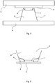
- Figure 1 shows the lighting device in cross section in the area through an LED 1. It is to be understood that the lamp can have several LEDs 1 and Figure 1 represents only one of these areas as an example.
- the LED 1 is attached to a circuit board 2, also referred to as a PCB, and electrically contacted thereon.
- the circuit board 2 is attached to a housing section 5 of the lighting device.
- a photometric cover 4 is provided, which protects the LED.
- the cover 4 is made transparent or at least partially transparent, for example made of a transparent plastic or glass.
- the entire area between the cover 4 and the LED 1 is formed by a lens body 3 made of silicone.
- the lens body 3 is firmly connected to the cover 4.
- the lens body 3 has side surfaces 7 which are positioned opposite the LED 1 in such a way that light radiation from the LED 1 is totally reflected on the side walls 7 before it enters the cover 4. For this, however, it is necessary for the lens body 3 to be precisely aligned with respect to the LED 1 is. According to the invention, mechanical contact is established between the lens body 3 and the LED 1 for this purpose. In the embodiment shown, the lens body 3 has a contact surface on the side facing the LED 1, with which the lens body 3 touches the LED 1 directly.
- the material of the lens body 3 is relatively soft because any mechanical stresses that can be compensated, for example, by different thermal expansion of the PCB 2 with respect to the cover 4, are thereby.
- the soft silicone material also has the advantage that no air inclusions arise between the LED 1 and the lens body 3 when the components are joined together.
- the lens body 3 also has run-on bevels 6 which are arranged in such a way that the lens body 3 is automatically aligned correctly with respect to the LED 1 when the components are joined together, ie In the embodiment shown, the LED 1 rests precisely in the middle on the lens body 3.
- the side walls 7 are also precisely aligned with respect to the LED 1, so that the desired light guidance can take place in the lens body 3.
- Figure 2 shows a variant of the embodiment according to Figure 1 .
- the lens body 3 is formed from two different silicone materials, a softer material 8 and a harder material 9. These materials can easily be produced using the 3D printing process.
- the softer lens material 8 is arranged in the region of the lens body 3 which is in contact with the LED 1. As a result, the LED 1 is protected, while the harder lens material 9 remains dimensionally stable, so that the desired direction of light can be achieved.
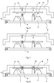
- the Figures 3 and 4 show the assembly of a lighting device in an embodiment similar to those in FIG Figures 1 and 2 illustrated embodiments.
- the lighting device has a housing 5 in which the cover 4 is positioned.
- the cover 4 is provided with a circumferential sealing ring 10 which has a plurality of ribs in order to be able to be mounted in the housing 5 with a friction fit.
- the lens body 3 are already firmly connected to the cover 4 before the device is assembled. Due to the shape of the lens body 3 in the area of the LED 1, the components are precisely aligned with one another when the lens bodies 3 are pushed onto the LEDs 1.
- the circuit board 2 of the LEDs 1 is held on the housing 5 solely by the pressing force of the lens body 3 on the LEDs 1.
- the lens material 3 is elastic enough to apply flexible contact pressure to the LEDs 1 or the circuit board 2, so that the circuit board 2 is held in the housing 5.
- a contact pressure is constantly applied to the circuit board 2 in the direction of the housing base, so that the circuit board 2 is in thermal contact with the housing base. As a result, a good heat exchange can take place between LEDs 1, the circuit board 2 and the housing 5, so that the housing 5 can serve as a heat sink for the LEDs 1.
- Figure 5 shows a variant of the embodiment according to Figures 3 and 4 .
- the optical cover 4 itself has sections which act in the form of a lens body similar to the lens body 3.
- the cover has 4 side surfaces on which total reflection of the light from the LEDs can also take place.
- a soft silicone material 8 is provided which, on the one hand, acts as a lens body 3 and, on the other hand, acts as a printing material between the cover 4 and the LED 1.
- the Figures 6 to 8 show a further embodiment in which the LEDs 1 are not in direct contact with the lens body 3, but an air gap is formed between the LED 1 and the lens body 3.
- the lens body 3 has a section 12 which is laterally formed from the material 9 of the lens body 3 and is directly connected to it.
- the section 12 On a side facing the circuit board 2, the section 12 has projections 14 which are formed from a softer silicone material 8.
- the projections 14 are guided through openings in the circuit board 2 (see FIG Figure 7 ) and further pushed onto fixing pins 13 on the bottom of the housing 5 (see Figure 8 ).
- the lens bodies 3 are precisely aligned with respect to the LEDs 1 due to the form fit between the projections and the through openings of the circuit board 2.
- both the circuit board 2 and the cover 4 are aligned in the housing 5 of the lighting device due to the form fit of the projections 14 with the fixing pins 13. In this embodiment, too, no further connection between the circuit board 2 and the housing 5 is necessary.
- the cover 4 with the lens bodies 3 and the circuit board 2 with the LEDs 1 can be held in the housing 5 of the lighting device solely due to the frictional connection between the lamellae of a seal 10 on the cover 4 and the frictional connection between the projections 14 and the fixing pins 13.
- the Figure 9 shows a variant of the embodiment according to Figures 6 to 8 .
- several pins are provided on section 12 of lens body 3.
- the pins are formed from the same harder silicone material 9 as the other sections of the lens body 3.
- the individual pins allow the section 12 of the lens body to be better clamped to the circuit board 2 and the fixing pin 13 of the housing 5. It should be understood that the pins of the section 12 of the lens body can be produced in the same 3D printing process as the other areas of the lens body 3.
- the shape of the lens body 3 can be designed differently.
- the lens body 3 always has a recess with respect to the LED 1, with side surfaces 7 serving as sections for total reflection.
- lens bodies can also be provided which have a spherical surface. This can arise in contact with the LED or in contact with the circuit board of the LED.
- the cover 4 can also assume different shapes.
- the cover 4 can not only be formed by a flat plate, as in FIG Figures 1 to 4 and 6 to 8 shown. It can itself form a free-form lens with various sections that serve to direct light. Sections can also be provided at which light is totally reflected.
- spherical sections can also be formed which serve to focus light or to expand light.
- a section of a lens body made of silicone is always provided between the cover and the LED or between the cover and a section of the circuit board 2 adjoining the LED.
Landscapes
- Engineering & Computer Science (AREA)
- General Engineering & Computer Science (AREA)
- Fastening Of Light Sources Or Lamp Holders (AREA)
- Securing Globes, Refractors, Reflectors Or The Like (AREA)
Priority Applications (1)
| Application Number | Priority Date | Filing Date | Title |
|---|---|---|---|
| EP22195165.0A EP4123219A1 (fr) | 2019-10-07 | 2020-10-06 | Positionnement d'un corps de lentille silicone sur une del |
Applications Claiming Priority (1)
| Application Number | Priority Date | Filing Date | Title |
|---|---|---|---|
| DE102019126892.3A DE102019126892A1 (de) | 2019-10-07 | 2019-10-07 | Positionierung eines silikonlinsenkörpers an einer led |
Related Child Applications (1)
| Application Number | Title | Priority Date | Filing Date |
|---|---|---|---|
| EP22195165.0A Division EP4123219A1 (fr) | 2019-10-07 | 2020-10-06 | Positionnement d'un corps de lentille silicone sur une del |
Publications (2)
| Publication Number | Publication Date |
|---|---|
| EP3805636A1 true EP3805636A1 (fr) | 2021-04-14 |
| EP3805636B1 EP3805636B1 (fr) | 2022-09-21 |
Family
ID=72752797
Family Applications (2)
| Application Number | Title | Priority Date | Filing Date |
|---|---|---|---|
| EP20200321.6A Active EP3805636B1 (fr) | 2019-10-07 | 2020-10-06 | Positionnement d'un corps de lentille silicone sur une del |
| EP22195165.0A Pending EP4123219A1 (fr) | 2019-10-07 | 2020-10-06 | Positionnement d'un corps de lentille silicone sur une del |
Family Applications After (1)
| Application Number | Title | Priority Date | Filing Date |
|---|---|---|---|
| EP22195165.0A Pending EP4123219A1 (fr) | 2019-10-07 | 2020-10-06 | Positionnement d'un corps de lentille silicone sur une del |
Country Status (2)
| Country | Link |
|---|---|
| EP (2) | EP3805636B1 (fr) |
| DE (1) | DE102019126892A1 (fr) |
Families Citing this family (1)
| Publication number | Priority date | Publication date | Assignee | Title |
|---|---|---|---|---|
| US11428398B1 (en) * | 2021-06-21 | 2022-08-30 | Troy-CSL Lighting Inc. | Adjustable lighting device with further optic |
Citations (4)
| Publication number | Priority date | Publication date | Assignee | Title |
|---|---|---|---|---|
| WO2010119580A1 (fr) * | 2009-04-16 | 2010-10-21 | 株式会社光波 | Module de source lumineuse |
| WO2012031703A1 (fr) | 2010-09-06 | 2012-03-15 | Heraeus Noblelight Gmbh | Procédé pour recouvrir un module puce-sur-plaque optoélectronique d'un revêtement |
| DE102017221844A1 (de) * | 2017-12-04 | 2019-06-06 | Osram Gmbh | Linsenkörper mit Aufweitungsvolumen und benachbarter Aussenkontur zum Positionieren |
| US20190285244A1 (en) * | 2018-03-14 | 2019-09-19 | Optic Arts, Inc. | Luminaire lens and housing system |
Family Cites Families (5)
| Publication number | Priority date | Publication date | Assignee | Title |
|---|---|---|---|---|
| ITUD20080145A1 (it) * | 2008-06-20 | 2009-12-21 | Laboratorio Bs S R L | Procedimento per la fabbricazione di una lente e relativa lente |
| GB2473185B (en) * | 2009-08-28 | 2012-05-30 | Ocean Led Ltd | Luminaire |
| GB2484713A (en) * | 2010-10-21 | 2012-04-25 | Optovate Ltd | Illumination apparatus |
| WO2014080398A1 (fr) * | 2012-11-26 | 2014-05-30 | Magic Lighting Optics | Dispositif d'éclairage extérieur |
| US10816165B2 (en) * | 2015-11-19 | 2020-10-27 | Lsi Industries, Inc. | LED luminaire assembly |
-
2019
- 2019-10-07 DE DE102019126892.3A patent/DE102019126892A1/de not_active Withdrawn
-
2020
- 2020-10-06 EP EP20200321.6A patent/EP3805636B1/fr active Active
- 2020-10-06 EP EP22195165.0A patent/EP4123219A1/fr active Pending
Patent Citations (4)
| Publication number | Priority date | Publication date | Assignee | Title |
|---|---|---|---|---|
| WO2010119580A1 (fr) * | 2009-04-16 | 2010-10-21 | 株式会社光波 | Module de source lumineuse |
| WO2012031703A1 (fr) | 2010-09-06 | 2012-03-15 | Heraeus Noblelight Gmbh | Procédé pour recouvrir un module puce-sur-plaque optoélectronique d'un revêtement |
| DE102017221844A1 (de) * | 2017-12-04 | 2019-06-06 | Osram Gmbh | Linsenkörper mit Aufweitungsvolumen und benachbarter Aussenkontur zum Positionieren |
| US20190285244A1 (en) * | 2018-03-14 | 2019-09-19 | Optic Arts, Inc. | Luminaire lens and housing system |
Also Published As
| Publication number | Publication date |
|---|---|
| EP3805636B1 (fr) | 2022-09-21 |
| EP4123219A1 (fr) | 2023-01-25 |
| DE102019126892A1 (de) | 2021-04-08 |
Similar Documents
| Publication | Publication Date | Title |
|---|---|---|
| EP3004724B1 (fr) | Dispositif d'éclairage pour phare de véhicule | |
| EP2863114B1 (fr) | Lampe de surface à DEL | |
| EP2521876A1 (fr) | Dispositif d'éclairage à del et procédé de production d'un dispositif d'éclairage à del | |
| EP2309296A1 (fr) | Structure de support pour une multitude de lentilles, lentille, système de lentilles et système optique | |
| DE202015009561U1 (de) | LED-Lampe und LED-Lichtquellenmodul dafür | |
| DE102006039705A1 (de) | Linsenvorsatz für einen Scheinwerfer | |
| EP2805106B1 (fr) | Luminaire pour locaux humides pourvu de del | |
| DE10016714C2 (de) | Strahlungsemittierende Vorrichtung | |
| DE102009042615A1 (de) | Anschlusselement zur elektrischen Anbindung einer LED | |
| EP3805636B1 (fr) | Positionnement d'un corps de lentille silicone sur une del | |
| EP3056805B1 (fr) | Optique allongée pour module à del | |
| EP2871411A1 (fr) | Élément optique pour un dispositif d'éclairage, et dispositif d'éclairage | |
| DE202010004874U1 (de) | LED-Modul mit Passiv-LED | |
| AT18709U1 (de) | Rettungszeichenleuchte mit Lichtleitelement | |
| EP1247690A2 (fr) | Feux de véhicule | |
| DE102015222187A1 (de) | Wannenleuchte | |
| CH715292B1 (de) | Optikrohling, Verfahren und Linearleuchte. | |
| EP2352045B1 (fr) | Agencement doté d'un élément de guidage de la lumière et d'un élément réflecteur | |
| DE102014005459B4 (de) | Beleuchtungsvorrichtung | |
| EP3088796B1 (fr) | Rail profile destine au positionnement de modules a del dans des condensateurs lumineux | |
| DE102020102005B4 (de) | Leuchte für die Automatisierungstechnik und Verfahren zur Herstellung der Leuchte | |
| DE202015103290U1 (de) | LED-Linse mit integrierter Verbindungstechnik | |
| DE102011102645B4 (de) | Operationsleuchte mit eingesetzter Lichteinheit, die eine nach außen abdichtende Abschlussplatte aufweist | |
| EP3376100A1 (fr) | Module d'éclairage led doté du support plat pour led | |
| EP4481718A1 (fr) | Lampe de signalisation de sécurité et/ou de sauvetage |
Legal Events
| Date | Code | Title | Description |
|---|---|---|---|
| PUAI | Public reference made under article 153(3) epc to a published international application that has entered the european phase |
Free format text: ORIGINAL CODE: 0009012 |
|
| STAA | Information on the status of an ep patent application or granted ep patent |
Free format text: STATUS: THE APPLICATION HAS BEEN PUBLISHED |
|
| AK | Designated contracting states |
Kind code of ref document: A1 Designated state(s): AL AT BE BG CH CY CZ DE DK EE ES FI FR GB GR HR HU IE IS IT LI LT LU LV MC MK MT NL NO PL PT RO RS SE SI SK SM TR |
|
| AX | Request for extension of the european patent |
Extension state: BA ME |
|
| STAA | Information on the status of an ep patent application or granted ep patent |
Free format text: STATUS: REQUEST FOR EXAMINATION WAS MADE |
|
| 17P | Request for examination filed |
Effective date: 20211013 |
|
| RBV | Designated contracting states (corrected) |
Designated state(s): AL AT BE BG CH CY CZ DE DK EE ES FI FR GB GR HR HU IE IS IT LI LT LU LV MC MK MT NL NO PL PT RO RS SE SI SK SM TR |
|
| GRAP | Despatch of communication of intention to grant a patent |
Free format text: ORIGINAL CODE: EPIDOSNIGR1 |
|
| STAA | Information on the status of an ep patent application or granted ep patent |
Free format text: STATUS: GRANT OF PATENT IS INTENDED |
|
| RIC1 | Information provided on ipc code assigned before grant |
Ipc: B29D 11/00 20060101ALN20220310BHEP Ipc: F21Y 115/10 20160101ALN20220310BHEP Ipc: F21Y 105/10 20160101ALN20220310BHEP Ipc: F21Y 103/10 20160101ALN20220310BHEP Ipc: F21V 31/00 20060101ALN20220310BHEP Ipc: F21V 3/06 20180101ALN20220310BHEP Ipc: F21V 17/00 20060101ALI20220310BHEP Ipc: F21V 7/00 20060101ALI20220310BHEP Ipc: F21V 5/00 20180101ALI20220310BHEP Ipc: F21V 3/02 20060101AFI20220310BHEP |
|
| INTG | Intention to grant announced |
Effective date: 20220411 |
|
| GRAS | Grant fee paid |
Free format text: ORIGINAL CODE: EPIDOSNIGR3 |
|
| GRAA | (expected) grant |
Free format text: ORIGINAL CODE: 0009210 |
|
| STAA | Information on the status of an ep patent application or granted ep patent |
Free format text: STATUS: THE PATENT HAS BEEN GRANTED |
|
| AK | Designated contracting states |
Kind code of ref document: B1 Designated state(s): AL AT BE BG CH CY CZ DE DK EE ES FI FR GB GR HR HU IE IS IT LI LT LU LV MC MK MT NL NO PL PT RO RS SE SI SK SM TR |
|
| REG | Reference to a national code |
Ref country code: GB Ref legal event code: FG4D Free format text: NOT ENGLISH |
|
| REG | Reference to a national code |
Ref country code: CH Ref legal event code: EP |
|
| REG | Reference to a national code |
Ref country code: IE Ref legal event code: FG4D Free format text: LANGUAGE OF EP DOCUMENT: GERMAN |
|
| REG | Reference to a national code |
Ref country code: DE Ref legal event code: R096 Ref document number: 502020001732 Country of ref document: DE |
|
| REG | Reference to a national code |
Ref country code: AT Ref legal event code: REF Ref document number: 1520111 Country of ref document: AT Kind code of ref document: T Effective date: 20221015 |
|
| REG | Reference to a national code |
Ref country code: LT Ref legal event code: MG9D |
|
| REG | Reference to a national code |
Ref country code: NL Ref legal event code: MP Effective date: 20220921 |
|
| PG25 | Lapsed in a contracting state [announced via postgrant information from national office to epo] |
Ref country code: SE Free format text: LAPSE BECAUSE OF FAILURE TO SUBMIT A TRANSLATION OF THE DESCRIPTION OR TO PAY THE FEE WITHIN THE PRESCRIBED TIME-LIMIT Effective date: 20220921 Ref country code: RS Free format text: LAPSE BECAUSE OF FAILURE TO SUBMIT A TRANSLATION OF THE DESCRIPTION OR TO PAY THE FEE WITHIN THE PRESCRIBED TIME-LIMIT Effective date: 20220921 Ref country code: NO Free format text: LAPSE BECAUSE OF FAILURE TO SUBMIT A TRANSLATION OF THE DESCRIPTION OR TO PAY THE FEE WITHIN THE PRESCRIBED TIME-LIMIT Effective date: 20221221 Ref country code: LV Free format text: LAPSE BECAUSE OF FAILURE TO SUBMIT A TRANSLATION OF THE DESCRIPTION OR TO PAY THE FEE WITHIN THE PRESCRIBED TIME-LIMIT Effective date: 20220921 Ref country code: LT Free format text: LAPSE BECAUSE OF FAILURE TO SUBMIT A TRANSLATION OF THE DESCRIPTION OR TO PAY THE FEE WITHIN THE PRESCRIBED TIME-LIMIT Effective date: 20220921 Ref country code: FI Free format text: LAPSE BECAUSE OF FAILURE TO SUBMIT A TRANSLATION OF THE DESCRIPTION OR TO PAY THE FEE WITHIN THE PRESCRIBED TIME-LIMIT Effective date: 20220921 |
|
| PG25 | Lapsed in a contracting state [announced via postgrant information from national office to epo] |
Ref country code: HR Free format text: LAPSE BECAUSE OF FAILURE TO SUBMIT A TRANSLATION OF THE DESCRIPTION OR TO PAY THE FEE WITHIN THE PRESCRIBED TIME-LIMIT Effective date: 20220921 Ref country code: GR Free format text: LAPSE BECAUSE OF FAILURE TO SUBMIT A TRANSLATION OF THE DESCRIPTION OR TO PAY THE FEE WITHIN THE PRESCRIBED TIME-LIMIT Effective date: 20221222 |
|
| PG25 | Lapsed in a contracting state [announced via postgrant information from national office to epo] |
Ref country code: SM Free format text: LAPSE BECAUSE OF FAILURE TO SUBMIT A TRANSLATION OF THE DESCRIPTION OR TO PAY THE FEE WITHIN THE PRESCRIBED TIME-LIMIT Effective date: 20220921 Ref country code: RO Free format text: LAPSE BECAUSE OF FAILURE TO SUBMIT A TRANSLATION OF THE DESCRIPTION OR TO PAY THE FEE WITHIN THE PRESCRIBED TIME-LIMIT Effective date: 20220921 Ref country code: PT Free format text: LAPSE BECAUSE OF FAILURE TO SUBMIT A TRANSLATION OF THE DESCRIPTION OR TO PAY THE FEE WITHIN THE PRESCRIBED TIME-LIMIT Effective date: 20230123 Ref country code: ES Free format text: LAPSE BECAUSE OF FAILURE TO SUBMIT A TRANSLATION OF THE DESCRIPTION OR TO PAY THE FEE WITHIN THE PRESCRIBED TIME-LIMIT Effective date: 20220921 Ref country code: CZ Free format text: LAPSE BECAUSE OF FAILURE TO SUBMIT A TRANSLATION OF THE DESCRIPTION OR TO PAY THE FEE WITHIN THE PRESCRIBED TIME-LIMIT Effective date: 20220921 |
|
| PG25 | Lapsed in a contracting state [announced via postgrant information from national office to epo] |
Ref country code: SK Free format text: LAPSE BECAUSE OF FAILURE TO SUBMIT A TRANSLATION OF THE DESCRIPTION OR TO PAY THE FEE WITHIN THE PRESCRIBED TIME-LIMIT Effective date: 20220921 Ref country code: PL Free format text: LAPSE BECAUSE OF FAILURE TO SUBMIT A TRANSLATION OF THE DESCRIPTION OR TO PAY THE FEE WITHIN THE PRESCRIBED TIME-LIMIT Effective date: 20220921 Ref country code: IS Free format text: LAPSE BECAUSE OF FAILURE TO SUBMIT A TRANSLATION OF THE DESCRIPTION OR TO PAY THE FEE WITHIN THE PRESCRIBED TIME-LIMIT Effective date: 20230121 Ref country code: EE Free format text: LAPSE BECAUSE OF FAILURE TO SUBMIT A TRANSLATION OF THE DESCRIPTION OR TO PAY THE FEE WITHIN THE PRESCRIBED TIME-LIMIT Effective date: 20220921 |
|
| REG | Reference to a national code |
Ref country code: DE Ref legal event code: R097 Ref document number: 502020001732 Country of ref document: DE |
|
| REG | Reference to a national code |
Ref country code: BE Ref legal event code: MM Effective date: 20221031 |
|
| PG25 | Lapsed in a contracting state [announced via postgrant information from national office to epo] |
Ref country code: NL Free format text: LAPSE BECAUSE OF FAILURE TO SUBMIT A TRANSLATION OF THE DESCRIPTION OR TO PAY THE FEE WITHIN THE PRESCRIBED TIME-LIMIT Effective date: 20220921 Ref country code: MC Free format text: LAPSE BECAUSE OF FAILURE TO SUBMIT A TRANSLATION OF THE DESCRIPTION OR TO PAY THE FEE WITHIN THE PRESCRIBED TIME-LIMIT Effective date: 20220921 Ref country code: LU Free format text: LAPSE BECAUSE OF NON-PAYMENT OF DUE FEES Effective date: 20221006 Ref country code: AL Free format text: LAPSE BECAUSE OF FAILURE TO SUBMIT A TRANSLATION OF THE DESCRIPTION OR TO PAY THE FEE WITHIN THE PRESCRIBED TIME-LIMIT Effective date: 20220921 |
|
| PLBE | No opposition filed within time limit |
Free format text: ORIGINAL CODE: 0009261 |
|
| STAA | Information on the status of an ep patent application or granted ep patent |
Free format text: STATUS: NO OPPOSITION FILED WITHIN TIME LIMIT |
|
| PG25 | Lapsed in a contracting state [announced via postgrant information from national office to epo] |
Ref country code: DK Free format text: LAPSE BECAUSE OF FAILURE TO SUBMIT A TRANSLATION OF THE DESCRIPTION OR TO PAY THE FEE WITHIN THE PRESCRIBED TIME-LIMIT Effective date: 20220921 |
|
| 26N | No opposition filed |
Effective date: 20230622 |
|
| PG25 | Lapsed in a contracting state [announced via postgrant information from national office to epo] |
Ref country code: SI Free format text: LAPSE BECAUSE OF FAILURE TO SUBMIT A TRANSLATION OF THE DESCRIPTION OR TO PAY THE FEE WITHIN THE PRESCRIBED TIME-LIMIT Effective date: 20220921 |
|
| PG25 | Lapsed in a contracting state [announced via postgrant information from national office to epo] |
Ref country code: BE Free format text: LAPSE BECAUSE OF NON-PAYMENT OF DUE FEES Effective date: 20221031 |
|
| PG25 | Lapsed in a contracting state [announced via postgrant information from national office to epo] |
Ref country code: IE Free format text: LAPSE BECAUSE OF NON-PAYMENT OF DUE FEES Effective date: 20221006 |
|
| PG25 | Lapsed in a contracting state [announced via postgrant information from national office to epo] |
Ref country code: CY Free format text: LAPSE BECAUSE OF FAILURE TO SUBMIT A TRANSLATION OF THE DESCRIPTION OR TO PAY THE FEE WITHIN THE PRESCRIBED TIME-LIMIT Effective date: 20220921 |
|
| PG25 | Lapsed in a contracting state [announced via postgrant information from national office to epo] |
Ref country code: MK Free format text: LAPSE BECAUSE OF FAILURE TO SUBMIT A TRANSLATION OF THE DESCRIPTION OR TO PAY THE FEE WITHIN THE PRESCRIBED TIME-LIMIT Effective date: 20220921 Ref country code: IT Free format text: LAPSE BECAUSE OF FAILURE TO SUBMIT A TRANSLATION OF THE DESCRIPTION OR TO PAY THE FEE WITHIN THE PRESCRIBED TIME-LIMIT Effective date: 20220921 |
|
| PG25 | Lapsed in a contracting state [announced via postgrant information from national office to epo] |
Ref country code: HU Free format text: LAPSE BECAUSE OF FAILURE TO SUBMIT A TRANSLATION OF THE DESCRIPTION OR TO PAY THE FEE WITHIN THE PRESCRIBED TIME-LIMIT; INVALID AB INITIO Effective date: 20201006 Ref country code: BG Free format text: LAPSE BECAUSE OF FAILURE TO SUBMIT A TRANSLATION OF THE DESCRIPTION OR TO PAY THE FEE WITHIN THE PRESCRIBED TIME-LIMIT Effective date: 20220921 |
|
| PG25 | Lapsed in a contracting state [announced via postgrant information from national office to epo] |
Ref country code: MT Free format text: LAPSE BECAUSE OF FAILURE TO SUBMIT A TRANSLATION OF THE DESCRIPTION OR TO PAY THE FEE WITHIN THE PRESCRIBED TIME-LIMIT Effective date: 20220921 |
|
| REG | Reference to a national code |
Ref country code: CH Ref legal event code: U11 Free format text: ST27 STATUS EVENT CODE: U-0-0-U10-U11 (AS PROVIDED BY THE NATIONAL OFFICE) Effective date: 20251101 |
|
| PG25 | Lapsed in a contracting state [announced via postgrant information from national office to epo] |
Ref country code: TR Free format text: LAPSE BECAUSE OF FAILURE TO SUBMIT A TRANSLATION OF THE DESCRIPTION OR TO PAY THE FEE WITHIN THE PRESCRIBED TIME-LIMIT Effective date: 20220921 |
|
| PGFP | Annual fee paid to national office [announced via postgrant information from national office to epo] |
Ref country code: DE Payment date: 20251020 Year of fee payment: 6 |
|
| PGFP | Annual fee paid to national office [announced via postgrant information from national office to epo] |
Ref country code: GB Payment date: 20251024 Year of fee payment: 6 |
|
| PGFP | Annual fee paid to national office [announced via postgrant information from national office to epo] |
Ref country code: AT Payment date: 20251021 Year of fee payment: 6 |
|
| PGFP | Annual fee paid to national office [announced via postgrant information from national office to epo] |
Ref country code: FR Payment date: 20251027 Year of fee payment: 6 |
|
| PGFP | Annual fee paid to national office [announced via postgrant information from national office to epo] |
Ref country code: CH Payment date: 20251101 Year of fee payment: 6 |