EP3805643A1 - Dispositif de commande pour un appareil électroménager destiné à la détection tactile et sans contact du changement de capacité, appareil électroménager ainsi que procédé - Google Patents
Dispositif de commande pour un appareil électroménager destiné à la détection tactile et sans contact du changement de capacité, appareil électroménager ainsi que procédé Download PDFInfo
- Publication number
- EP3805643A1 EP3805643A1 EP20197454.0A EP20197454A EP3805643A1 EP 3805643 A1 EP3805643 A1 EP 3805643A1 EP 20197454 A EP20197454 A EP 20197454A EP 3805643 A1 EP3805643 A1 EP 3805643A1
- Authority
- EP
- European Patent Office
- Prior art keywords
- operating
- user
- designed
- detection device
- user interface
- Prior art date
- Legal status (The legal status is an assumption and is not a legal conclusion. Google has not performed a legal analysis and makes no representation as to the accuracy of the status listed.)
- Granted
Links
Images

Classifications
-
- H—ELECTRICITY
- H03—ELECTRONIC CIRCUITRY
- H03K—PULSE TECHNIQUE
- H03K17/00—Electronic switching or gating, i.e. not by contact-making and –breaking
- H03K17/94—Electronic switching or gating, i.e. not by contact-making and –breaking characterised by the way in which the control signals are generated
- H03K17/96—Touch switches
- H03K17/962—Capacitive touch switches
-
- H—ELECTRICITY
- H03—ELECTRONIC CIRCUITRY
- H03K—PULSE TECHNIQUE
- H03K17/00—Electronic switching or gating, i.e. not by contact-making and –breaking
- H03K17/94—Electronic switching or gating, i.e. not by contact-making and –breaking characterised by the way in which the control signals are generated
- H03K17/96—Touch switches
- H03K17/962—Capacitive touch switches
- H03K17/9622—Capacitive touch switches using a plurality of detectors, e.g. keyboard
-
- F—MECHANICAL ENGINEERING; LIGHTING; HEATING; WEAPONS; BLASTING
- F24—HEATING; RANGES; VENTILATING
- F24C—DOMESTIC STOVES OR RANGES ; DETAILS OF DOMESTIC STOVES OR RANGES, OF GENERAL APPLICATION
- F24C7/00—Stoves or ranges heated by electric energy
- F24C7/08—Arrangement or mounting of control or safety devices
-
- F—MECHANICAL ENGINEERING; LIGHTING; HEATING; WEAPONS; BLASTING
- F24—HEATING; RANGES; VENTILATING
- F24C—DOMESTIC STOVES OR RANGES ; DETAILS OF DOMESTIC STOVES OR RANGES, OF GENERAL APPLICATION
- F24C7/00—Stoves or ranges heated by electric energy
- F24C7/08—Arrangement or mounting of control or safety devices
- F24C7/082—Arrangement or mounting of control or safety devices on ranges, e.g. control panels, illumination
-
- H—ELECTRICITY
- H03—ELECTRONIC CIRCUITRY
- H03K—PULSE TECHNIQUE
- H03K17/00—Electronic switching or gating, i.e. not by contact-making and –breaking
- H03K17/94—Electronic switching or gating, i.e. not by contact-making and –breaking characterised by the way in which the control signals are generated
- H03K17/965—Switches controlled by moving an element forming part of the switch
- H03K17/967—Switches controlled by moving an element forming part of the switch having a plurality of control members, e.g. keyboard
-
- H—ELECTRICITY
- H03—ELECTRONIC CIRCUITRY
- H03K—PULSE TECHNIQUE
- H03K17/00—Electronic switching or gating, i.e. not by contact-making and –breaking
- H03K17/94—Electronic switching or gating, i.e. not by contact-making and –breaking characterised by the way in which the control signals are generated
- H03K17/965—Switches controlled by moving an element forming part of the switch
- H03K17/975—Switches controlled by moving an element forming part of the switch using a capacitive movable element
-
- H—ELECTRICITY
- H03—ELECTRONIC CIRCUITRY
- H03K—PULSE TECHNIQUE
- H03K2217/00—Indexing scheme related to electronic switching or gating, i.e. not by contact-making or -breaking covered by H03K17/00
- H03K2217/94—Indexing scheme related to electronic switching or gating, i.e. not by contact-making or -breaking covered by H03K17/00 characterised by the way in which the control signal is generated
- H03K2217/94057—Rotary switches
- H03K2217/94073—Rotary switches with capacitive detection
-
- H—ELECTRICITY
- H03—ELECTRONIC CIRCUITRY
- H03K—PULSE TECHNIQUE
- H03K2217/00—Indexing scheme related to electronic switching or gating, i.e. not by contact-making or -breaking covered by H03K17/00
- H03K2217/94—Indexing scheme related to electronic switching or gating, i.e. not by contact-making or -breaking covered by H03K17/00 characterised by the way in which the control signal is generated
- H03K2217/96—Touch switches
- H03K2217/96054—Double function: touch detection combined with detection of a movable element
-
- H—ELECTRICITY
- H03—ELECTRONIC CIRCUITRY
- H03K—PULSE TECHNIQUE
- H03K2217/00—Indexing scheme related to electronic switching or gating, i.e. not by contact-making or -breaking covered by H03K17/00
- H03K2217/94—Indexing scheme related to electronic switching or gating, i.e. not by contact-making or -breaking covered by H03K17/00 characterised by the way in which the control signal is generated
- H03K2217/96—Touch switches
- H03K2217/9607—Capacitive touch switches
- H03K2217/960755—Constructional details of capacitive touch and proximity switches
- H03K2217/96077—Constructional details of capacitive touch and proximity switches comprising an electrode which is floating
Definitions
- the invention relates to an operating device for a household appliance with a user interface, which is designed to set at least one operating condition of the household appliance when operated by a user of the operating device, wherein a capacitive detection device for capacitive detection of the operation is formed on an underside of the user interface Underside opposite an upper side, which faces the user during operation and forms an outside of the operating device.
- the invention also relates to a household appliance with an operating device and a method for operating an operating device.
- a large number of operating devices for operating a household appliance are already sufficiently known from the prior art.
- different touch-sensitive operating devices are known for this purpose, which can be used in an operating panel.
- Corresponding detection devices for detecting the touch are located in particular on electronics of the operating device.
- detachable operating elements are already known for, in particular, troughs as household appliances, for example a so-called "twist pad”.
- the object of the present invention is to create an operating device, a household appliance and a method by means of which a household appliance can be operated in a highly functional manner.
- One aspect of the invention relates to an operating device for a household appliance with a user interface which is designed to be used when operated by a user Control device to set at least one operating condition of the household appliance, with a capacitive detection device for capacitive detection of the operation being formed on an underside of the user interface, the underside being formed opposite an upper side which faces the user during operation and forms an outside of the operating device.
- the detection device is designed as a touch-sensitive detection device and is designed to detect the operation of the user by touching the upper side by the user on the basis of a touch-based capacity change and is also designed to detect the operation of the user by one of the To detect user-operated control element of the control device on the user interface on the basis of a contactless change in capacitance by the control element.
- an operation on the touch-sensitive detection device can be carried out in a touch-based manner.
- a corresponding operation can take place by means of an operating element which can be arranged on the operating surface. This makes it possible for the user to operate the operating device in a highly functional manner. In particular, the user can thus decide in a personalized manner whether he or she would like to operate the household appliance in a touch-based or non-contact manner with the control element.
- a robust operating device for use in a household appliance when using / evaluating capacitive detection devices which can also be referred to as touch sensors
- a stable and defined mechanical structure is necessary, since the touch Sensor technology is sensitive to material and / or distance tolerances between the sensor and the finger. This also minimizes mechanical tolerances between the sensor and the finger.
- a corresponding operating device can thereby be provided with fewer variants.
- a panel design for example a switch front of the household appliance, that has a brand and product-specific expression of the operating device, which is also known as a User interface are referred to, or the control panel has, can be made possible without complex hardware changes.
- control elements are arranged both on the user interface, in particular "on-screen", so to speak, that is, the operation takes place via or on the display or also outside the display, so to speak "off-screen” - that means individual keys and sliders are next to the display.
- the user interface can also have a display device on which corresponding symbols or input options can be displayed.
- the user interface is preferably made of glass or polymethyl methacrylate.
- the polymethyl methacrylate can also be referred to as PMMA.
- these are user interfaces that are easy to process. In particular, these can be easily produced and easy operation by the user is made possible. Furthermore, easy cleaning by the user is possible, for example.
- the operating device has a microcontroller which is designed to generate a control signal for setting the operating condition as a function of the detected change in capacitance.
- the microcontroller can be a so-called “micro C logic”, for example.
- different circuits and electronic components can be formed within the microcontroller in order to be able to carry out a corresponding evaluation and generation of the control signal.
- the microcontroller is preferably designed to generate the control signal when the predetermined change in capacitance threshold value of the detected change in capacitance is exceeded.
- the control signal and the The operating condition is only set when the capacity change threshold is exceeded. This makes it possible, for example, for an operation to take place if the user interface is touched unintentionally. This enables reliable operation of the operating device.
- the user interface is preferably designed without a break.
- the user interface does not have any openings or holes.
- the electronics in particular a film sensor, can be better protected from environmental influences.
- the electronics are better protected against ESD (Electro-Static-Discharge) and thus also have electrical robustness, in particular with regard to electromagnetic compatibility.
- electrical air and creepage distances can be avoided, whereby the operating device is also better protected against ESD.
- this makes the user interface easier to clean for the user.
- the capacitive detection device is designed as a film sensor.
- the film sensor is a so-called two-dimensional film sensor.
- the film sensor is in particular a one-piece film sensor.
- the film sensor is thus arranged directly behind the user interface.
- the film sensor is glued to the user interface, that is, the sensor is firmly connected to the user interface.
- the film sensor has the particular advantage that it can be produced using a roll-to-roll process (R2R process), for example.
- the film sensor is designed to evaluate both the position and the setting of a mechanical operating element, for example an incremental encoder or program selector, and to carry out the operation with the human finger itself.
- the film sensor is thus designed in particular as a touch-sensitive film sensor.
- the film sensor has a diamond-like structure of detection elements of the capacitive detection device, in particular the film sensor thus has a so-called diamond pattern.
- a self-capacitance and a counter-capacitance can be detected by means of the diamond pattern.
- a diamond pattern creates a so-called multi-finger gesture recognition, which can also be referred to as "multi-touch" capability. This also enables different inputs to be evaluated at the same time. This makes it possible for an operation by the user to be recorded in a simple and yet reliable, highly functional manner.
- the film sensor has a multiplicity of detection elements lying next to one another, which are evaluated independently of one another by means of the capacitive detection device.
- a kind of backgammon structure of the sensor can thereby be provided.
- the detection elements thus have a structure which corresponds to a backgammon board.
- these detection elements have a corresponding backgammon geometry. This enables a simple self-capacitance measurement to be carried out.
- the backgammon structure or the large number of detection elements lying next to one another can be divided into so-called logical areas, so that these can be evaluated independently of one another. This enables a simple yet reliable recording of the operation by the user.
- the touch-sensitive detection device is designed as a touch-sensitive display device and is designed to display at least one symbol and to detect the touch.
- the capacitive detection device or the touch-sensitive detection device can be provided as a touchscreen.
- both the display of symbols and the touch detection can be carried out with the touch-sensitive display device.
- the corresponding operating condition can be set by the user by touching the corresponding symbol.
- the film sensor is designed to be larger than the touch-sensitive display device, in other words than the touch-sensitive touchscreen.
- this enables a further area to be arranged in addition to the touch-sensitive display area (off-screen), on which the control element is arranged, for example for operation can without impairing the view of the touchscreen (on-screen).
- an operating area can thus be overlapped with the operating element and with the touchscreen. This realizes a highly functional operating device.
- control element is designed to be placed on and removed from the control surface in a non-destructive manner.
- the operating element is not permanently connected to the operating device, but can be removed. If the control element is defective, it can simply be replaced.
- such an operating element can be a so-called “twist pad”.
- the operating element can, for example, be mechanically latched to the operating surface and yet be removable again.
- control element can have electrodes for this purpose, for example metal surfaces, which are arranged near the control surface so that they are connected to the touchable control surface, so that a single electrode, for example, in self-capacitance mode or the electrode pattern in a mutual capacitance mode, whereby, for example, a multi-capacitance mode can also be used.
- Touch capability is provided, when the control element is touched / operated on the touch sensor, a corresponding intensity pattern is generated, which is evaluated by, for example, a microcontroller and converted into an operating operation, in particular into setting the operating condition.
- the operating element can be designed to be moved freely movably on the operating surface. This enables, in particular, individual operation by the user. The user can move the control element freely on the user interface and choose where a corresponding operation can be carried out.
- the film sensor configuration makes it possible, in particular, that the operator interface can be configured to be relatively large, so that the operator can operate the operator control device at different points.
- the operating element is designed to be magnetic, and the operating element is by means of a magnetic device Control device held on the user interface.
- the operating element can be fixed magnetically on the operating surface.
- both the operating element and the operating surface can have corresponding magnetic elements, so that a corresponding fixing is made possible.
- a free mobility of the operating element relative to the operating surface can be realized by the magnet device.
- the operating element can also be prevented from falling down, for example when the operating device is aligned vertically when used as intended.
- the capacitive detection device is designed to detect a self-capacitance and / or a mutual capacitance for detecting the change in capacitance.
- the capacitive detection device is capable of both "self-capacitance” and "mutual capacitance”. This makes it possible to operate the operating device in different ways. In particular, this enables operation to be carried out reliably both by touch and without contact.
- Complex operating elements can be implemented in particular in the acquisition of mutual capacitance.
- different functions within the operating device or within the household appliance can thereby be operated with the one operating element.
- An electrical functionality of the operating element is thereby largely decoupled, in particular from mechanical influences.
- the capacitive detection device is used to detect a relative position of the operating element and the at least one operating condition is set as a function of the detected position.
- the operating condition can be set as a function of the position relative to the user interface. For example, it can be provided that if the control element is located on a first side of the user interface, for example on a left side of the user interface, a first operating condition can be set. If the control element is located on a second side of the user interface, for example on a right side of the user interface, a second operating condition can be set.
- the intensity pattern measured by the detection device can be implemented depending on the size and shape of the respective electrodes within the operating element parallel to the operating surface, whereby the absolute position, in particular the absolute angular position, of the operating element can be determined.
- the operating condition can then be set as a function of this.
- the capacitive detection device is designed to detect a relative position of the operating element with respect to the user interface and the at least one operating condition is set as a function of the detected position.
- the detection device can detect a corresponding change in capacitance depending on the measured intensity pattern depending on the distance between the electrodes and the user interface; in particular, this allows the distance changes to be carried out, such as when a button is pressed, for example a "tactile switch".
- a twist pad can also be used, for example.
- a corresponding operating condition can be set. This makes it possible, in a highly functional manner, to use different operating elements and to set the different operating conditions of the household appliance in a highly functional manner.
- the capacitive detection device is designed to detect a multi-finger gesture control.
- this enables different operating conditions of the household appliance to be set for different gestures with the finger.
- a first operating condition can be set by touching with two fingers, while a further operating condition can be set by touching only one finger.
- a higher-level menu of the operating device can be selected by means of a “zoom out movement”. By "zooming in” you can again go to a submenu.
- the operating element has a multiplicity of electrodes which interact with the capacitive detection device and the contactless operation is detected on the basis of this interaction.
- both the position of the control element and the position of the control element can thus be evaluated.
- a large number of electrodes which can be arranged in a ring shape within the operating element, for example, a large number of different settings can be made, which in turn can set a large number of different operating conditions on the household appliance.
- a large number of different operating conditions can thus be set by means of the one operating element.
- the operating device can be operated by the user in a highly functional manner.
- the capacitive detection device is designed to simultaneously detect the touch-based change in capacitance and the non-contact change in capacitance.
- the user touches the user interface with his finger and sets an operating condition and at the same time sets a corresponding additional operating condition with the control element or can set the operating condition both by touch and by means of the control element.
- the operating device can be provided in a highly functional and user-friendly manner.
- Another aspect of the invention relates to a household appliance with an operating device, the household appliance in particular a cooking appliance according to the preceding aspect.
- the cooking device can be designed as an oven or hob.
- the user interface is arranged horizontally and / or vertically on the household appliance when the household appliance is used as intended.
- the operating device can be arranged both horizontally and vertically on the household appliance. Different possible uses for the operating device are thereby realized.
- Yet another aspect of the invention relates to a method for operating an operating device for a household appliance, in which by means of a user interface at Operation by a user of the operating device, at least one operating condition of the household appliance is set, with a capacitive detection device for capacitive detection of the operation being provided on an underside of the operating surface, by means of which the operation is capacitively detected, the underside being made available opposite an upper side, which at Operation is facing the user and forms an outside of the operating device, so that the detection device is provided as a touch-sensitive detection device, and the operation of the user is detected by touching the upper side by the user on the basis of a touch-based capacity change and, in addition, the operation of the user by a Operating element of the operating device operated by the user is detected on the basis of a contactless change in capacitance by the operating element.
- Advantageous embodiments of the operating device are to be regarded as advantageous embodiments of the household appliance and of the method.
- the operating device and the household appliance have objective features which enable the method or an advantageous embodiment thereof to be carried out.
- top, bottom, rear, horizontal, vertical, depth direction, “width direction”, “height direction” etc. are given positions when the control device or household appliance is used and arranged as intended and orientations indicated.
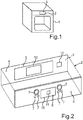
- Fig. 1 shows an embodiment of a household appliance 1 in a schematic perspective view.
- the household appliance 1 is designed in particular as a cooking appliance.
- the household appliance 1 can be designed as an oven.
- the household appliance 1 can also be designed as a hob, for example in a combination device.
- the household appliance 1 has an operating device 2.
- the operating device 2 can have a user interface 3.
- the user interface 3 is arranged in particular horizontally and / or vertically of the household appliance 1, in the present case arranged horizontally.
- Fig. 2 shows an embodiment of the operating device 2 in a schematic exploded view.
- the operating device 2 has the operating surface 3, which is designed to be used when operated by a user 14 (not shown) Fig. 4 ) of the operating device 2 to set at least one operating condition of the household appliance 1, with a capacitive detection device 5 for capacitive detection of the operation being formed on an underside 4 of the operating surface 3, the underside 4 of an upper side 6, which faces the user 14 during operation, and a Forms outside of the operating device 2 is formed.
- the capacitive detection device 5 is designed as a touch-sensitive detection device 5 and is designed to detect the operation of the user 14 by touching the top 6 by the user 14 on the basis of a touch-based change in capacitance and is also designed to perform the operation of the user 14 through an operating element 7 of the operating device 2 operated by the user 14 on the operating surface 6 of a contactless change in capacitance through the operating element 7.
- a robust operating device 2 for use in a household appliance 1 when using / evaluating capacitive detection devices 5, which can also be referred to as touch sensors is achieved in which a stable and defined mechanical construction is necessary, since the touch sensors are sensitive to material and / or distance tolerances between the sensor and the finger. This also minimizes mechanical tolerances between the sensor and the finger.
- a corresponding operating device 2 can thereby be provided with fewer variants.
- a panel design for example a switch front of the household appliance 1, which has a brand and product-specific form of the operating device 2, which can also be referred to as a user interface, or the operating panel, can be made possible without complex hardware changes.
- the operating elements 7 are arranged both on the user interface 3, in particular "on-screen", so to speak, that is, the operation takes place via or on the display or also outside the display, so to speak "off-screen” - that means individual buttons and sliders are next to the display.
- the user interface 3 can also have a display device 9 on which corresponding symbols 11 or input options can be displayed.
- mechanical operating elements 7, such as, for example, a "rotary encoder", a program selector or button elements, which in particular have no electrical openings, can be selected as the operating element 7.
- EMC electromagnetic compatibility
- operating elements 7 are arranged on the user interface 3, in particular on the upper side 6.
- it can be both so-called rotary switches and toggle switches or key switches.
- the operating element 7 can also be a so-called twist pad.
- the capacitive detection device 5 is designed as a film sensor 8.
- the film sensor 8 is arranged as a two-dimensional film sensor directly behind the user interface 3.
- the film sensor 8 is glued directly onto the user interface 3, so that the film sensor 8 is firmly connected to the user interface 3.
- the film sensor can be a film sensor 8 which was produced using the so-called roll-to-roll method.
- the user interface 3 is formed in particular from glass or polymethyl methacrylate.
- the polymethyl methacrylate (PMMA) is also referred to as Plexiglas.
- PMMA polymethyl methacrylate
- a simple yet reliable user interface 3 can thereby be provided.
- the capacitive detection device 5 is designed to detect a self-capacitance and / or a counter-capacitance for detecting the change in capacitance.
- the capacitive detection device 5 is capable of both "self-capacitance” and "mutual capacitance”. This makes it possible to operate the operating device 2 in different ways. In particular, this enables operation to be carried out reliably both by touch and without contact.
- complex operating elements 7 can be implemented in the mutual capacitance detection. In particular, different functions within the operating device 2 or within the household appliance 1 can thereby be operated with the one operating element 7. An electrical functionality of the operating element 7 is thereby largely decoupled, in particular from mechanical influences.
- the touch-sensitive detection device 5 can in particular also be designed as a touch-sensitive display device 9.
- the touch-sensitive detection device has a display area 10.
- the display area 10 is also touch-sensitive. This enables, for example, at least one symbol 11 to be displayed on the display area 10. By touching the symbol 11, for example, the operating condition can be set.
- the film sensor 8 is made larger than the display area 10.
- the operating element 7 can thus be provided next to the display area 10. It is thus made possible that, in addition to the display area 10, a corresponding operation of the operating device 2 can also be carried out by the operating elements 7 in addition to the display area 10.
- the operating device 2 can have a microcontroller 12 which is designed to generate a control signal for setting the operating condition as a function of the detected change in capacitance.
- the microcontroller 12 is designed to generate the control signal when a predetermined change in capacitance threshold value of the detected change in capacitance is exceeded.
- At least one operating condition of the household appliance 1 is set by means of the user interface 3 when operated by the user 14 of the operating device 2, with the capacitive detection device 5 for capacitive detection on the underside 4 of the user interface 3 the operation is provided, by means of which the operation is capacitively recorded, the underside 3 being provided opposite the upper side 6, which faces the user 14 during operation and forms an outside of the operating device 2, the detection device 5 being provided as a touch-sensitive detection device 5 and the operation of the user 14 is detected by the user 14 touching the top 6 on the basis of a contactless change in capacitance and, in addition, the operation of the user 14 by the operating element 7 of the operating device 2 operated by the user 14 is detected on the basis of the contactless change in capacitance by the operating element 7.
- FIG. 3 shows an embodiment of the operating device 2 in a schematic perspective view.
- the film sensor 8 is designed, in particular, like a diamond.
- the film sensor 8 has a diamond-like structure of detection elements 13 of the capacitive detection device 5. Due to the diamond-like structure, in particular a self-capacitance measurement can be carried out.
- the diamond-like structure can in particular also be referred to as a diamond pattern. This enables so-called multi-finger gesture recognition in particular. In other words, different inputs can be evaluated at the same time.
- Fig. 4 shows an embodiment of the operating device 2 in a further schematic view Fig. 4 that the operating device 2 is designed so that the operating element 7 can be placed on and removed from the user interface 3 without being destroyed.
- the operating element 7 is designed to be magnetic, and the operating element 7 can be held on the operating surface 3 by means of a magnetic device 15 of the operating device 2.
- the Fig. 4 Furthermore, that the operating element 7 is designed to be moved freely on the operating surface 3.
- the capacitive detection device 5 is designed to detect a relative position of the operating element 7 with respect to the user interface 3 and the at least one operating condition is set as a function of the detected position. In particular, this can be carried out in the mutual capacitance measurement, in particular in the mutual capacitance mode, of the operating device 2.
- the intensity pattern measured by the detection device 5 can be measured parallel to the user interface 3 depending on the size and shape of the electrodes 16, whereby the absolute position, in particular the absolute angular position, of the operating element 7 can be determined.
- the operating condition of the household appliance 1 can in turn be set.
- the capacitive detection device 5 is designed to detect multi-finger gesture recognition.
- it is User interface 3 designed to be multi-touch capable.
- the operating device 2 can in particular be designed in the mutual capacitance mode. By touching or operating the operating element 7, a corresponding intensity pattern is generated, which can be evaluated by the microcontroller 12 and converted into a corresponding operating operation.
- the Fig. 4 in particular that the user interface 3 is designed without a break.
- the user interface 3 has no openings, so that in particular the electronics behind the user interface 3 are protected from weather conditions.
- the capacitive detection device 5 is designed to simultaneously detect the contact-based change in capacitance and the non-contact change in capacitance.
- hybrid operation can be performed.
- both the operation by means of the operating element 7 and by touching the user 14 on the display area 10 can thus be implemented.
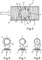
- Fig. 5 shows an embodiment of the operating device 2 in a further schematic view Fig. 5 the user interface 3.
- the film sensor 8 has a multiplicity of detection elements 13 lying next to one another, which are evaluated independently of one another by means of the capacitive detection device 5.
- the film sensor 8 can be designed with a so-called backgammon structure.
- the backgammon structure is a structure of the film sensor 8 which corresponds to a backgammon board.
- a self-capacitance can thereby be reliably detected.
- the user interface 3 can be divided into logical areas depending on the geometry, so that these logical areas can be evaluated independently of one another.
- the Fig. 5 the control element 7, which can have a plurality of electrodes 16, is shown in dashed lines. A corresponding evaluation of the control signal can thereby be carried out as a function of the respective electrodes 16, in particular as a function of the respective position of the electrodes 16.
- Figures 6 to 8 show an operating element 7 in different variants or in different positions, the different positions being carried out by different movements B.
- the different movements B the Figures 6 to 8 can be carried out both individually and together, whereby different operating conditions can also be set.
- Fig. 6 shows that the operating element 7 can be rotated, for example, whereby a corresponding operation or an operational setting can be set.
- Fig. 7 shows that, for example, by touching a side area of the operating element 7, the operating element 7 can be tilted, whereby an operating condition of the household appliance 3 can also be set.
- Fig. 8 shows that an operating condition can also be set by pressing the control element 7 in the center. In particular, a push movement can thereby be implemented, for example.
- the capacitive detection device 5 is designed to detect a relative position of the operating element 7 with respect to the user interface 3, and at least one operating condition is set as a function of the detected position. Furthermore, it can be provided that the operating element 7 has a plurality of the electrodes 16, which interact with the capacitive detection device 5 and the contactless operation is detected on the basis of this interaction.
Landscapes
- Engineering & Computer Science (AREA)
- Chemical & Material Sciences (AREA)
- Combustion & Propulsion (AREA)
- Mechanical Engineering (AREA)
- General Engineering & Computer Science (AREA)
- Switches That Are Operated By Magnetic Or Electric Fields (AREA)
- User Interface Of Digital Computer (AREA)
- Push-Button Switches (AREA)
Applications Claiming Priority (1)
| Application Number | Priority Date | Filing Date | Title |
|---|---|---|---|
| DE102019215463.8A DE102019215463A1 (de) | 2019-10-09 | 2019-10-09 | Bedienvorrichtung für ein Haushaltsgerät zur berührungsbasierten und zur berührungslosen Kapazitätsänderungserfassung, Haushaltsgerät sowie Verfahren |
Publications (2)
| Publication Number | Publication Date |
|---|---|
| EP3805643A1 true EP3805643A1 (fr) | 2021-04-14 |
| EP3805643B1 EP3805643B1 (fr) | 2025-02-26 |
Family
ID=72615586
Family Applications (1)
| Application Number | Title | Priority Date | Filing Date |
|---|---|---|---|
| EP20197454.0A Active EP3805643B1 (fr) | 2019-10-09 | 2020-09-22 | Dispositif de commande pour un appareil électroménager destiné à la détection tactile et sans contact du changement de capacité, appareil électroménager ainsi que procédé |
Country Status (3)
| Country | Link |
|---|---|
| EP (1) | EP3805643B1 (fr) |
| CN (1) | CN112653442B (fr) |
| DE (1) | DE102019215463A1 (fr) |
Citations (3)
| Publication number | Priority date | Publication date | Assignee | Title |
|---|---|---|---|---|
| DE102014200888A1 (de) * | 2014-01-20 | 2015-07-23 | BSH Hausgeräte GmbH | Bedienvorrichtung für ein Haushaltsgerät mit einem Kratzschutzelement an einer Unterseite eines abnehmbaren Bedienelements sowie Haushaltsgerät mit einer derartigen Bedienvorrichtung |
| DE102014223371A1 (de) * | 2014-11-17 | 2016-05-19 | BSH Hausgeräte GmbH | Bedienung eines Haushaltsgeräts mittels eines abnehmbaren Bedienelements |
| US20180217690A1 (en) * | 2015-04-02 | 2018-08-02 | Jörg R. Bauer | Touchpad and system for detecting an object on a detection surface, and generating and outputting object-specific information |
Family Cites Families (6)
| Publication number | Priority date | Publication date | Assignee | Title |
|---|---|---|---|---|
| DE102011119137A1 (de) * | 2010-11-25 | 2012-05-31 | Marquardt Gmbh | Bedienvorrichtung |
| EP2493077B1 (fr) * | 2011-02-24 | 2016-09-28 | Miele & Cie. KG | Dispositif de commande d'un appareil ménager |
| DE102014115285A1 (de) * | 2014-10-21 | 2016-04-21 | Miele & Cie. Kg | Bedienungshilfe für ein Sensorbedienelement, Haushaltsgerät und Verfahren zum Betreiben eines Sensorbedienelements |
| DE102016223476A1 (de) * | 2016-11-25 | 2018-05-30 | BSH Hausgeräte GmbH | Haptisches Bedienelement für ein Haushaltsgerät |
| DE102018202740A1 (de) * | 2018-02-23 | 2019-08-29 | BSH Hausgeräte GmbH | Bedienelement mit integriertem Gestenerkennungssensor, Bedienvorrichtung und Haushaltsgerät |
| DE102018209552A1 (de) * | 2018-06-14 | 2019-12-19 | BSH Hausgeräte GmbH | Tragbares Bedienelement mit Basiseinheit, Dreherkennungsteil und auf der Basiseinheit kippbar angeordnetem Bedienteil sowie Bedienvorrichtung für ein Gargerät |
-
2019
- 2019-10-09 DE DE102019215463.8A patent/DE102019215463A1/de not_active Ceased
-
2020
- 2020-09-22 EP EP20197454.0A patent/EP3805643B1/fr active Active
- 2020-10-09 CN CN202011071916.8A patent/CN112653442B/zh active Active
Patent Citations (3)
| Publication number | Priority date | Publication date | Assignee | Title |
|---|---|---|---|---|
| DE102014200888A1 (de) * | 2014-01-20 | 2015-07-23 | BSH Hausgeräte GmbH | Bedienvorrichtung für ein Haushaltsgerät mit einem Kratzschutzelement an einer Unterseite eines abnehmbaren Bedienelements sowie Haushaltsgerät mit einer derartigen Bedienvorrichtung |
| DE102014223371A1 (de) * | 2014-11-17 | 2016-05-19 | BSH Hausgeräte GmbH | Bedienung eines Haushaltsgeräts mittels eines abnehmbaren Bedienelements |
| US20180217690A1 (en) * | 2015-04-02 | 2018-08-02 | Jörg R. Bauer | Touchpad and system for detecting an object on a detection surface, and generating and outputting object-specific information |
Also Published As
| Publication number | Publication date |
|---|---|
| EP3805643B1 (fr) | 2025-02-26 |
| DE102019215463A1 (de) | 2021-04-15 |
| CN112653442A (zh) | 2021-04-13 |
| CN112653442B (zh) | 2025-08-26 |
Similar Documents
| Publication | Publication Date | Title |
|---|---|---|
| DE112008000906T5 (de) | Zweidimensionaler Positionssensor | |
| DE69534404T2 (de) | Verfahren zum kompensieren von unbeabsichtigten Bewegungen bei einer Antipgeste auf einer Berührungssensorfläche | |
| DE102011075276B4 (de) | Kapazitive Sensoreinrichtung sowie Verfahren zum Betrieb einer Eingabeeinrichtung | |
| DE102010027732A1 (de) | Zweidimensionaler Positionssensor | |
| DE102012103030B3 (de) | Verfahren zur Bedienung eines Industrieroboters | |
| DE112008001800T5 (de) | Zweidimensionales Touchpanel | |
| DE112014004615T5 (de) | Erfassen und Differenzieren von Berührungen von leitfähigen Gegenständen unterschiedlicher Größe auf einem kapazitiven Taster | |
| DE102006031376A1 (de) | Zweidimensionaler Positionssensor | |
| DE112008001966T5 (de) | Zweidimensionaler Positionssensor | |
| EP2019983A2 (fr) | Dispositif de saisie | |
| DE202005021427U1 (de) | Elektronische Vorrichtung mit berührungsempfindlicher Eingabeeinrichtung | |
| DE102012107761A1 (de) | Elektronisches Gerät und zugehöriges Betriebsverfahren | |
| DE102011010914A1 (de) | Eingabegerät, insbesondere in Form einer Computertastatur | |
| DE202007017303U1 (de) | Computermaus | |
| DE69902896T2 (de) | Positionierung eines cursors auf einem rechnerbildschirm | |
| DE112012003889T5 (de) | Verfahren, Vorrichtung und Computerprogramm, die zum Zeigen auf ein Objekt dienen | |
| EP2748368B1 (fr) | Appareil électroménager équipé d'un dispositif de commande et d'affichage tactile | |
| EP4121841A1 (fr) | Ensemble actionneur rotatif | |
| EP3805643B1 (fr) | Dispositif de commande pour un appareil électroménager destiné à la détection tactile et sans contact du changement de capacité, appareil électroménager ainsi que procédé | |
| DE102011006733A1 (de) | Bedienvorrichtung mit verbesserter taktiler Bedienbarkeit für eine tontechnische Anlage | |
| WO2004109491A2 (fr) | Dispositif de commande | |
| DE102009019910B4 (de) | Gestenerkennung | |
| DE102016014507A1 (de) | Bedienanordnung für ein Kraftfahrzeug und Verfahren zur Auswahl eines Listenelements aus einer auf einem Display angezeigten Liste | |
| EP3224696B1 (fr) | Procédé permettant l'interaction tactile entre un utilisateur et un appareil électronique, et appareil électronique associé | |
| DE102020201735A1 (de) | Vorrichtung und Verfahren zur Erkennung von Berührungsbefehlen |
Legal Events
| Date | Code | Title | Description |
|---|---|---|---|
| PUAI | Public reference made under article 153(3) epc to a published international application that has entered the european phase |
Free format text: ORIGINAL CODE: 0009012 |
|
| STAA | Information on the status of an ep patent application or granted ep patent |
Free format text: STATUS: THE APPLICATION HAS BEEN PUBLISHED |
|
| AK | Designated contracting states |
Kind code of ref document: A1 Designated state(s): AL AT BE BG CH CY CZ DE DK EE ES FI FR GB GR HR HU IE IS IT LI LT LU LV MC MK MT NL NO PL PT RO RS SE SI SK SM TR |
|
| AX | Request for extension of the european patent |
Extension state: BA ME |
|
| STAA | Information on the status of an ep patent application or granted ep patent |
Free format text: STATUS: REQUEST FOR EXAMINATION WAS MADE |
|
| 17P | Request for examination filed |
Effective date: 20211014 |
|
| RBV | Designated contracting states (corrected) |
Designated state(s): AL AT BE BG CH CY CZ DE DK EE ES FI FR GB GR HR HU IE IS IT LI LT LU LV MC MK MT NL NO PL PT RO RS SE SI SK SM TR |
|
| STAA | Information on the status of an ep patent application or granted ep patent |
Free format text: STATUS: EXAMINATION IS IN PROGRESS |
|
| 17Q | First examination report despatched |
Effective date: 20230829 |
|
| GRAP | Despatch of communication of intention to grant a patent |
Free format text: ORIGINAL CODE: EPIDOSNIGR1 |
|
| STAA | Information on the status of an ep patent application or granted ep patent |
Free format text: STATUS: GRANT OF PATENT IS INTENDED |
|
| INTG | Intention to grant announced |
Effective date: 20241021 |
|
| GRAS | Grant fee paid |
Free format text: ORIGINAL CODE: EPIDOSNIGR3 |
|
| GRAA | (expected) grant |
Free format text: ORIGINAL CODE: 0009210 |
|
| STAA | Information on the status of an ep patent application or granted ep patent |
Free format text: STATUS: THE PATENT HAS BEEN GRANTED |
|
| AK | Designated contracting states |
Kind code of ref document: B1 Designated state(s): AL AT BE BG CH CY CZ DE DK EE ES FI FR GB GR HR HU IE IS IT LI LT LU LV MC MK MT NL NO PL PT RO RS SE SI SK SM TR |
|
| REG | Reference to a national code |
Ref country code: GB Ref legal event code: FG4D Free format text: NOT ENGLISH |
|
| REG | Reference to a national code |
Ref country code: CH Ref legal event code: EP |
|
| REG | Reference to a national code |
Ref country code: DE Ref legal event code: R096 Ref document number: 502020010472 Country of ref document: DE |
|
| REG | Reference to a national code |
Ref country code: IE Ref legal event code: FG4D Free format text: LANGUAGE OF EP DOCUMENT: GERMAN |
|
| REG | Reference to a national code |
Ref country code: NL Ref legal event code: MP Effective date: 20250226 |
|
| PG25 | Lapsed in a contracting state [announced via postgrant information from national office to epo] |
Ref country code: RS Free format text: LAPSE BECAUSE OF FAILURE TO SUBMIT A TRANSLATION OF THE DESCRIPTION OR TO PAY THE FEE WITHIN THE PRESCRIBED TIME-LIMIT Effective date: 20250526 |
|
| PG25 | Lapsed in a contracting state [announced via postgrant information from national office to epo] |
Ref country code: FI Free format text: LAPSE BECAUSE OF FAILURE TO SUBMIT A TRANSLATION OF THE DESCRIPTION OR TO PAY THE FEE WITHIN THE PRESCRIBED TIME-LIMIT Effective date: 20250226 |
|
| PG25 | Lapsed in a contracting state [announced via postgrant information from national office to epo] |
Ref country code: PL Free format text: LAPSE BECAUSE OF FAILURE TO SUBMIT A TRANSLATION OF THE DESCRIPTION OR TO PAY THE FEE WITHIN THE PRESCRIBED TIME-LIMIT Effective date: 20250226 |
|
| PG25 | Lapsed in a contracting state [announced via postgrant information from national office to epo] |
Ref country code: ES Free format text: LAPSE BECAUSE OF FAILURE TO SUBMIT A TRANSLATION OF THE DESCRIPTION OR TO PAY THE FEE WITHIN THE PRESCRIBED TIME-LIMIT Effective date: 20250226 |
|
| REG | Reference to a national code |
Ref country code: LT Ref legal event code: MG9D |
|
| PG25 | Lapsed in a contracting state [announced via postgrant information from national office to epo] |
Ref country code: NO Free format text: LAPSE BECAUSE OF FAILURE TO SUBMIT A TRANSLATION OF THE DESCRIPTION OR TO PAY THE FEE WITHIN THE PRESCRIBED TIME-LIMIT Effective date: 20250526 Ref country code: IS Free format text: LAPSE BECAUSE OF FAILURE TO SUBMIT A TRANSLATION OF THE DESCRIPTION OR TO PAY THE FEE WITHIN THE PRESCRIBED TIME-LIMIT Effective date: 20250626 |
|
| PG25 | Lapsed in a contracting state [announced via postgrant information from national office to epo] |
Ref country code: NL Free format text: LAPSE BECAUSE OF FAILURE TO SUBMIT A TRANSLATION OF THE DESCRIPTION OR TO PAY THE FEE WITHIN THE PRESCRIBED TIME-LIMIT Effective date: 20250226 |
|
| PG25 | Lapsed in a contracting state [announced via postgrant information from national office to epo] |
Ref country code: HR Free format text: LAPSE BECAUSE OF FAILURE TO SUBMIT A TRANSLATION OF THE DESCRIPTION OR TO PAY THE FEE WITHIN THE PRESCRIBED TIME-LIMIT Effective date: 20250226 |
|
| PG25 | Lapsed in a contracting state [announced via postgrant information from national office to epo] |
Ref country code: LV Free format text: LAPSE BECAUSE OF FAILURE TO SUBMIT A TRANSLATION OF THE DESCRIPTION OR TO PAY THE FEE WITHIN THE PRESCRIBED TIME-LIMIT Effective date: 20250226 Ref country code: PT Free format text: LAPSE BECAUSE OF FAILURE TO SUBMIT A TRANSLATION OF THE DESCRIPTION OR TO PAY THE FEE WITHIN THE PRESCRIBED TIME-LIMIT Effective date: 20250626 |
|
| PG25 | Lapsed in a contracting state [announced via postgrant information from national office to epo] |
Ref country code: BG Free format text: LAPSE BECAUSE OF FAILURE TO SUBMIT A TRANSLATION OF THE DESCRIPTION OR TO PAY THE FEE WITHIN THE PRESCRIBED TIME-LIMIT Effective date: 20250226 Ref country code: GR Free format text: LAPSE BECAUSE OF FAILURE TO SUBMIT A TRANSLATION OF THE DESCRIPTION OR TO PAY THE FEE WITHIN THE PRESCRIBED TIME-LIMIT Effective date: 20250527 |
|
| PG25 | Lapsed in a contracting state [announced via postgrant information from national office to epo] |
Ref country code: SE Free format text: LAPSE BECAUSE OF FAILURE TO SUBMIT A TRANSLATION OF THE DESCRIPTION OR TO PAY THE FEE WITHIN THE PRESCRIBED TIME-LIMIT Effective date: 20250226 |
|
| PG25 | Lapsed in a contracting state [announced via postgrant information from national office to epo] |
Ref country code: SM Free format text: LAPSE BECAUSE OF FAILURE TO SUBMIT A TRANSLATION OF THE DESCRIPTION OR TO PAY THE FEE WITHIN THE PRESCRIBED TIME-LIMIT Effective date: 20250226 |
|
| PG25 | Lapsed in a contracting state [announced via postgrant information from national office to epo] |
Ref country code: DK Free format text: LAPSE BECAUSE OF FAILURE TO SUBMIT A TRANSLATION OF THE DESCRIPTION OR TO PAY THE FEE WITHIN THE PRESCRIBED TIME-LIMIT Effective date: 20250226 |
|
| PGFP | Annual fee paid to national office [announced via postgrant information from national office to epo] |
Ref country code: DE Payment date: 20250930 Year of fee payment: 6 |
|
| PG25 | Lapsed in a contracting state [announced via postgrant information from national office to epo] |
Ref country code: IT Free format text: LAPSE BECAUSE OF FAILURE TO SUBMIT A TRANSLATION OF THE DESCRIPTION OR TO PAY THE FEE WITHIN THE PRESCRIBED TIME-LIMIT Effective date: 20250226 |
|
| PGFP | Annual fee paid to national office [announced via postgrant information from national office to epo] |
Ref country code: GB Payment date: 20250923 Year of fee payment: 6 |
|
| PGFP | Annual fee paid to national office [announced via postgrant information from national office to epo] |
Ref country code: FR Payment date: 20250926 Year of fee payment: 6 |
|
| PG25 | Lapsed in a contracting state [announced via postgrant information from national office to epo] |
Ref country code: EE Free format text: LAPSE BECAUSE OF FAILURE TO SUBMIT A TRANSLATION OF THE DESCRIPTION OR TO PAY THE FEE WITHIN THE PRESCRIBED TIME-LIMIT Effective date: 20250226 Ref country code: CZ Free format text: LAPSE BECAUSE OF FAILURE TO SUBMIT A TRANSLATION OF THE DESCRIPTION OR TO PAY THE FEE WITHIN THE PRESCRIBED TIME-LIMIT Effective date: 20250226 |
|
| PG25 | Lapsed in a contracting state [announced via postgrant information from national office to epo] |
Ref country code: RO Free format text: LAPSE BECAUSE OF FAILURE TO SUBMIT A TRANSLATION OF THE DESCRIPTION OR TO PAY THE FEE WITHIN THE PRESCRIBED TIME-LIMIT Effective date: 20250226 |
|
| PG25 | Lapsed in a contracting state [announced via postgrant information from national office to epo] |
Ref country code: SK Free format text: LAPSE BECAUSE OF FAILURE TO SUBMIT A TRANSLATION OF THE DESCRIPTION OR TO PAY THE FEE WITHIN THE PRESCRIBED TIME-LIMIT Effective date: 20250226 |
|
| REG | Reference to a national code |
Ref country code: DE Ref legal event code: R097 Ref document number: 502020010472 Country of ref document: DE |
|
| PLBE | No opposition filed within time limit |
Free format text: ORIGINAL CODE: 0009261 |
|
| STAA | Information on the status of an ep patent application or granted ep patent |
Free format text: STATUS: NO OPPOSITION FILED WITHIN TIME LIMIT |
|
| 26N | No opposition filed |
Effective date: 20251127 |