EP3807501B1 - Système et procédé d'exécution d'opérations sur un moteur - Google Patents
Système et procédé d'exécution d'opérations sur un moteur Download PDFInfo
- Publication number
- EP3807501B1 EP3807501B1 EP19746204.7A EP19746204A EP3807501B1 EP 3807501 B1 EP3807501 B1 EP 3807501B1 EP 19746204 A EP19746204 A EP 19746204A EP 3807501 B1 EP3807501 B1 EP 3807501B1
- Authority
- EP
- European Patent Office
- Prior art keywords
- robotic arm
- engine
- component
- laser beam
- interior
- Prior art date
- Legal status (The legal status is an assumption and is not a legal conclusion. Google has not performed a legal analysis and makes no representation as to the accuracy of the status listed.)
- Active
Links
Images



Classifications
-
- F—MECHANICAL ENGINEERING; LIGHTING; HEATING; WEAPONS; BLASTING
- F01—MACHINES OR ENGINES IN GENERAL; ENGINE PLANTS IN GENERAL; STEAM ENGINES
- F01D—NON-POSITIVE DISPLACEMENT MACHINES OR ENGINES, e.g. STEAM TURBINES
- F01D25/00—Component parts, details, or accessories, not provided for in, or of interest apart from, other groups
- F01D25/28—Supporting or mounting arrangements, e.g. for turbine casing
- F01D25/285—Temporary support structures, e.g. for testing, assembling, installing, repairing; Assembly methods using such structures
-
- B—PERFORMING OPERATIONS; TRANSPORTING
- B64—AIRCRAFT; AVIATION; COSMONAUTICS
- B64F—GROUND OR AIRCRAFT-CARRIER-DECK INSTALLATIONS SPECIALLY ADAPTED FOR USE IN CONNECTION WITH AIRCRAFT; DESIGNING, MANUFACTURING, ASSEMBLING, CLEANING, MAINTAINING OR REPAIRING AIRCRAFT, NOT OTHERWISE PROVIDED FOR; HANDLING, TRANSPORTING, TESTING OR INSPECTING AIRCRAFT COMPONENTS, NOT OTHERWISE PROVIDED FOR
- B64F5/00—Designing, manufacturing, assembling, cleaning, maintaining or repairing aircraft, not otherwise provided for; Handling, transporting, testing or inspecting aircraft components, not otherwise provided for
- B64F5/40—Maintaining or repairing aircraft
-
- B—PERFORMING OPERATIONS; TRANSPORTING
- B23—MACHINE TOOLS; METAL-WORKING NOT OTHERWISE PROVIDED FOR
- B23B—TURNING; BORING
- B23B39/00—General-purpose boring or drilling machines or devices; Sets of boring and/or drilling machines
- B23B39/14—General-purpose boring or drilling machines or devices; Sets of boring and/or drilling machines with special provision to enable the machine or the drilling or boring head to be moved into any desired position, e.g. with respect to immovable work
-
- B—PERFORMING OPERATIONS; TRANSPORTING
- B23—MACHINE TOOLS; METAL-WORKING NOT OTHERWISE PROVIDED FOR
- B23P—METAL-WORKING NOT OTHERWISE PROVIDED FOR; COMBINED OPERATIONS; UNIVERSAL MACHINE TOOLS
- B23P6/00—Restoring or reconditioning objects
- B23P6/002—Repairing turbine components, e.g. moving or stationary blades, rotors
-
- B—PERFORMING OPERATIONS; TRANSPORTING
- B25—HAND TOOLS; PORTABLE POWER-DRIVEN TOOLS; MANIPULATORS
- B25J—MANIPULATORS; CHAMBERS PROVIDED WITH MANIPULATION DEVICES
- B25J11/00—Manipulators not otherwise provided for
- B25J11/005—Manipulators for mechanical processing tasks
-
- B—PERFORMING OPERATIONS; TRANSPORTING
- B25—HAND TOOLS; PORTABLE POWER-DRIVEN TOOLS; MANIPULATORS
- B25J—MANIPULATORS; CHAMBERS PROVIDED WITH MANIPULATION DEVICES
- B25J13/00—Controls for manipulators
- B25J13/08—Controls for manipulators by means of sensing devices, e.g. viewing or touching devices
- B25J13/087—Controls for manipulators by means of sensing devices, e.g. viewing or touching devices for sensing other physical parameters, e.g. electrical or chemical properties
-
- B—PERFORMING OPERATIONS; TRANSPORTING
- B25—HAND TOOLS; PORTABLE POWER-DRIVEN TOOLS; MANIPULATORS
- B25J—MANIPULATORS; CHAMBERS PROVIDED WITH MANIPULATION DEVICES
- B25J13/00—Controls for manipulators
- B25J13/08—Controls for manipulators by means of sensing devices, e.g. viewing or touching devices
- B25J13/088—Controls for manipulators by means of sensing devices, e.g. viewing or touching devices with position, velocity or acceleration sensors
-
- B—PERFORMING OPERATIONS; TRANSPORTING
- B25—HAND TOOLS; PORTABLE POWER-DRIVEN TOOLS; MANIPULATORS
- B25J—MANIPULATORS; CHAMBERS PROVIDED WITH MANIPULATION DEVICES
- B25J15/00—Gripping heads and other end effectors
- B25J15/0019—End effectors other than grippers
-
- B—PERFORMING OPERATIONS; TRANSPORTING
- B25—HAND TOOLS; PORTABLE POWER-DRIVEN TOOLS; MANIPULATORS
- B25J—MANIPULATORS; CHAMBERS PROVIDED WITH MANIPULATION DEVICES
- B25J15/00—Gripping heads and other end effectors
- B25J15/0052—Gripping heads and other end effectors multiple gripper units or multiple end effectors
- B25J15/0066—Gripping heads and other end effectors multiple gripper units or multiple end effectors with different types of end effectors, e.g. gripper and welding gun
-
- B—PERFORMING OPERATIONS; TRANSPORTING
- B25—HAND TOOLS; PORTABLE POWER-DRIVEN TOOLS; MANIPULATORS
- B25J—MANIPULATORS; CHAMBERS PROVIDED WITH MANIPULATION DEVICES
- B25J9/00—Program-controlled manipulators
- B25J9/06—Program-controlled manipulators characterised by multi-articulated arms
-
- B—PERFORMING OPERATIONS; TRANSPORTING
- B25—HAND TOOLS; PORTABLE POWER-DRIVEN TOOLS; MANIPULATORS
- B25J—MANIPULATORS; CHAMBERS PROVIDED WITH MANIPULATION DEVICES
- B25J9/00—Program-controlled manipulators
- B25J9/16—Program controls
- B25J9/1679—Program controls characterised by the tasks executed
- B25J9/1682—Dual arm manipulator; Coordination of several manipulators
-
- F—MECHANICAL ENGINEERING; LIGHTING; HEATING; WEAPONS; BLASTING
- F01—MACHINES OR ENGINES IN GENERAL; ENGINE PLANTS IN GENERAL; STEAM ENGINES
- F01D—NON-POSITIVE DISPLACEMENT MACHINES OR ENGINES, e.g. STEAM TURBINES
- F01D5/00—Blades; Blade-carrying members; Heating, heat-insulating, cooling or antivibration means on the blades or the members
- F01D5/005—Repairing methods or devices
-
- F—MECHANICAL ENGINEERING; LIGHTING; HEATING; WEAPONS; BLASTING
- F01—MACHINES OR ENGINES IN GENERAL; ENGINE PLANTS IN GENERAL; STEAM ENGINES
- F01D—NON-POSITIVE DISPLACEMENT MACHINES OR ENGINES, e.g. STEAM TURBINES
- F01D25/00—Component parts, details, or accessories, not provided for in, or of interest apart from, other groups
-
- F—MECHANICAL ENGINEERING; LIGHTING; HEATING; WEAPONS; BLASTING
- F01—MACHINES OR ENGINES IN GENERAL; ENGINE PLANTS IN GENERAL; STEAM ENGINES
- F01D—NON-POSITIVE DISPLACEMENT MACHINES OR ENGINES, e.g. STEAM TURBINES
- F01D25/00—Component parts, details, or accessories, not provided for in, or of interest apart from, other groups
- F01D25/002—Cleaning of turbomachines
-
- F—MECHANICAL ENGINEERING; LIGHTING; HEATING; WEAPONS; BLASTING
- F01—MACHINES OR ENGINES IN GENERAL; ENGINE PLANTS IN GENERAL; STEAM ENGINES
- F01D—NON-POSITIVE DISPLACEMENT MACHINES OR ENGINES, e.g. STEAM TURBINES
- F01D25/00—Component parts, details, or accessories, not provided for in, or of interest apart from, other groups
- F01D25/007—Preventing corrosion
-
- F—MECHANICAL ENGINEERING; LIGHTING; HEATING; WEAPONS; BLASTING
- F05—INDEXING SCHEMES RELATING TO ENGINES OR PUMPS IN VARIOUS SUBCLASSES OF CLASSES F01-F04
- F05D—INDEXING SCHEME FOR ASPECTS RELATING TO NON-POSITIVE-DISPLACEMENT MACHINES OR ENGINES, GAS-TURBINES OR JET-PROPULSION PLANTS
- F05D2220/00—Application
- F05D2220/30—Application in turbines
- F05D2220/32—Application in turbines in gas turbines
- F05D2220/323—Application in turbines in gas turbines for aircraft propulsion, e.g. jet engines
-
- F—MECHANICAL ENGINEERING; LIGHTING; HEATING; WEAPONS; BLASTING
- F05—INDEXING SCHEMES RELATING TO ENGINES OR PUMPS IN VARIOUS SUBCLASSES OF CLASSES F01-F04
- F05D—INDEXING SCHEME FOR ASPECTS RELATING TO NON-POSITIVE-DISPLACEMENT MACHINES OR ENGINES, GAS-TURBINES OR JET-PROPULSION PLANTS
- F05D2230/00—Manufacture
- F05D2230/10—Manufacture by removing material
- F05D2230/12—Manufacture by removing material by spark erosion methods
-
- F—MECHANICAL ENGINEERING; LIGHTING; HEATING; WEAPONS; BLASTING
- F05—INDEXING SCHEMES RELATING TO ENGINES OR PUMPS IN VARIOUS SUBCLASSES OF CLASSES F01-F04
- F05D—INDEXING SCHEME FOR ASPECTS RELATING TO NON-POSITIVE-DISPLACEMENT MACHINES OR ENGINES, GAS-TURBINES OR JET-PROPULSION PLANTS
- F05D2230/00—Manufacture
- F05D2230/10—Manufacture by removing material
- F05D2230/13—Manufacture by removing material using lasers
-
- F—MECHANICAL ENGINEERING; LIGHTING; HEATING; WEAPONS; BLASTING
- F05—INDEXING SCHEMES RELATING TO ENGINES OR PUMPS IN VARIOUS SUBCLASSES OF CLASSES F01-F04
- F05D—INDEXING SCHEME FOR ASPECTS RELATING TO NON-POSITIVE-DISPLACEMENT MACHINES OR ENGINES, GAS-TURBINES OR JET-PROPULSION PLANTS
- F05D2230/00—Manufacture
- F05D2230/10—Manufacture by removing material
- F05D2230/14—Micromachining
-
- F—MECHANICAL ENGINEERING; LIGHTING; HEATING; WEAPONS; BLASTING
- F05—INDEXING SCHEMES RELATING TO ENGINES OR PUMPS IN VARIOUS SUBCLASSES OF CLASSES F01-F04
- F05D—INDEXING SCHEME FOR ASPECTS RELATING TO NON-POSITIVE-DISPLACEMENT MACHINES OR ENGINES, GAS-TURBINES OR JET-PROPULSION PLANTS
- F05D2230/00—Manufacture
- F05D2230/20—Manufacture essentially without removing material
- F05D2230/23—Manufacture essentially without removing material by permanently joining parts together
- F05D2230/232—Manufacture essentially without removing material by permanently joining parts together by welding
- F05D2230/233—Electron beam welding
-
- F—MECHANICAL ENGINEERING; LIGHTING; HEATING; WEAPONS; BLASTING
- F05—INDEXING SCHEMES RELATING TO ENGINES OR PUMPS IN VARIOUS SUBCLASSES OF CLASSES F01-F04
- F05D—INDEXING SCHEME FOR ASPECTS RELATING TO NON-POSITIVE-DISPLACEMENT MACHINES OR ENGINES, GAS-TURBINES OR JET-PROPULSION PLANTS
- F05D2230/00—Manufacture
- F05D2230/20—Manufacture essentially without removing material
- F05D2230/23—Manufacture essentially without removing material by permanently joining parts together
- F05D2230/232—Manufacture essentially without removing material by permanently joining parts together by welding
- F05D2230/234—Laser welding
-
- F—MECHANICAL ENGINEERING; LIGHTING; HEATING; WEAPONS; BLASTING
- F05—INDEXING SCHEMES RELATING TO ENGINES OR PUMPS IN VARIOUS SUBCLASSES OF CLASSES F01-F04
- F05D—INDEXING SCHEME FOR ASPECTS RELATING TO NON-POSITIVE-DISPLACEMENT MACHINES OR ENGINES, GAS-TURBINES OR JET-PROPULSION PLANTS
- F05D2230/00—Manufacture
- F05D2230/20—Manufacture essentially without removing material
- F05D2230/23—Manufacture essentially without removing material by permanently joining parts together
- F05D2230/232—Manufacture essentially without removing material by permanently joining parts together by welding
- F05D2230/235—TIG or MIG welding
-
- F—MECHANICAL ENGINEERING; LIGHTING; HEATING; WEAPONS; BLASTING
- F05—INDEXING SCHEMES RELATING TO ENGINES OR PUMPS IN VARIOUS SUBCLASSES OF CLASSES F01-F04
- F05D—INDEXING SCHEME FOR ASPECTS RELATING TO NON-POSITIVE-DISPLACEMENT MACHINES OR ENGINES, GAS-TURBINES OR JET-PROPULSION PLANTS
- F05D2230/00—Manufacture
- F05D2230/80—Repairing, retrofitting or upgrading methods
-
- F—MECHANICAL ENGINEERING; LIGHTING; HEATING; WEAPONS; BLASTING
- F05—INDEXING SCHEMES RELATING TO ENGINES OR PUMPS IN VARIOUS SUBCLASSES OF CLASSES F01-F04
- F05D—INDEXING SCHEME FOR ASPECTS RELATING TO NON-POSITIVE-DISPLACEMENT MACHINES OR ENGINES, GAS-TURBINES OR JET-PROPULSION PLANTS
- F05D2260/00—Function
- F05D2260/60—Fluid transfer
- F05D2260/607—Preventing clogging or obstruction of flow paths by dirt, dust, or foreign particles
Definitions
- the present subject matter relates generally to a system for performing an operation on a component of an engine, and a method for performing the same.
- At least one known gas turbine engine includes, in serial flow arrangement, a compressor for compressing air flowing through the engine, a combustor for mixing fuel with the compressed air such that the mixture may be ignited, a turbine for providing power to the compressor.
- the compressor, combustor and turbine are sometimes collectively referred to as the core engine.
- one or more the components of the gas turbine engine may become worn or damaged.
- cracks may form in or beneath a surface of one or more of the components due to, e.g., repeated stress during operation, exposure to temperatures in excess of a designed temperature limit, etc.
- the gas turbine engine is typically removed from the aircraft (e.g., uninstalled from beneath a wing of an aircraft) and disassembled to expose the component.
- the component may be repaired, and the engine reassembled and reinstalled, such that the engine may be used further.
- US 2005/0224474 A1 relates to a cleaning system and method that utilizes a portable workhead to direct a pulsed laser beam to a surface of a generator, turbine or boiler component.
- US 9,073,156 B2 relates to a method of supporting a tool in an assembled apparatus.
- US 2005/0235493 A1 relates to a method for in-frame repairing of thermal barrier coating on a gas turbine component.
- US 8,927,897 B2 relates to a maintenance device including a flexible member with an inspection end sized to be inserted through an inspection port of a workpiece such as a gas turbine engine or a blade of a gas turbine engine.
- US 2012/0275873 A1 relates to a method of drilling one or more holes, substantially in situ, in a turbomachine casing.
- EP 3222751 A1 relates to methods for repairing a surface of a component within a gas turbine engine.
- EP 2116340 A1 relates to a synchronous robotic operation on a structure having a confined space.
- first, second, and third may be used interchangeably to distinguish one component from another and are not intended to signify location or importance of the individual components.
- forward and aft refer to relative positions within a component or system, and refer to the normal operational attitude of the component or system.
- forward refers to a position closer to a distal end of the robotic arm and aft refers to a position closer to a root end of the robotic arm.
- Coupled refers to both direct coupling, fixing, or attaching, as well as indirect coupling, fixing, or attaching through one or more intermediate components or features, unless otherwise specified herein.
- Approximating language is applied to modify any quantitative representation that could permissibly vary without resulting in a change in the basic function to which it is related. Accordingly, a value modified by a term or terms, such as “about”, “approximately”, and “substantially”, are not to be limited to the precise value specified. In at least some instances, the approximating language may correspond to the precision of an instrument for measuring the value, or the precision of the methods or machines for constructing or manufacturing the components and/or systems. For example, the approximating language may refer to being within a 10 percent margin.
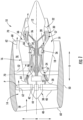
- Fig. 1 is a schematic, cross-sectional view of a turbine engine in accordance with an exemplary embodiment of the present disclosure. More particularly, for the embodiment of Fig. 1 , the turbine engine is a high-bypass turbofan jet engine 10, referred to herein as "turbofan engine 10." As shown in Fig. 1 , the turbofan engine 10 defines an axial direction A (extending parallel to a longitudinal centerline 12 provided for reference) and a radial direction R. In general, the turbofan engine 10 includes a fan section 14 and a turbomachine 16 disposed downstream from the fan section 14.
- the exemplary turbomachine 16 depicted generally includes an outer casing 18 that defines an annular inlet 20. Within the outer casing 18 may be considered an interior 19 of the turbomachine 16, and more specifically, of the turbofan engine 10.
- the outer casing 18 encases, in serial flow relationship, a compressor section including a booster or low pressure (LP) compressor 22 and a high pressure (HP) compressor 24; a combustion section 26; a turbine section including a high pressure (HP) turbine 28 and a low pressure (LP) turbine 30; and a jet exhaust nozzle section 32.
- the compressor section, combustion section 26, turbine section, and exhaust nozzle section 32 together define at least in part a core air flowpath 37 through the turbomachine 16.
- a high pressure (HP) shaft or spool 34 (or rather a high pressure spool assembly, as described below) drivingly connects the HP turbine 28 to the HP compressor 24.
- a low pressure (LP) shaft or spool 36 drivingly connects the LP turbine 30 to the LP compressor 22.
- the fan section 14 includes a variable pitch fan 38 having a plurality of fan blades 40 coupled to a disk 42 in a spaced apart manner.
- the fan blades 40 extend outwardly from disk 42 generally along the radial direction R.
- Each fan blade 40 is rotatable relative to the disk 42 about a pitch axis P by virtue of the fan blades 40 being operatively coupled to a suitable actuation member 44 configured to collectively vary the pitch of the fan blades 40 in unison.
- the fan blades 40, disk 42, and actuation member 44 are together rotatable about the longitudinal centerline 12 by LP shaft 36 across a power gear box 46.
- the power gear box 46 includes a plurality of gears for stepping down the rotational speed of the LP shaft 36 to a more efficient rotational fan speed.
- the disk 42 is covered by rotatable front hub 48 aerodynamically contoured to promote an airflow through the plurality of fan blades 40.
- the exemplary fan section 14 includes an annular fan casing or outer nacelle 50 that circumferentially surrounds the fan 38 and/or at least a portion of the turbomachine 16.
- the nacelle 50 is supported relative to the turbomachine 16 by a plurality of circumferentially-spaced outlet guide vanes 52.
- the nacelle 50 extends over an outer portion of the turbomachine 16 so as to define a bypass airflow passage 56 therebetween.
- a volume of air 58 enters the turbofan 10 through an associated inlet 60 of the nacelle 50 and/or fan section 14.
- a first portion of the air 58 as indicated by arrows 62 is directed or routed into the bypass airflow passage 56 and a second portion of the air 58 as indicated by arrow 64 is directed or routed into the LP compressor 22.
- the ratio between the first portion of air 62 and the second portion of air 64 is commonly known as a bypass ratio.
- the pressure of the second portion of air 64 is then increased as it is routed through the high pressure (HP) compressor 24 and into the combustion section 26, where it is mixed with fuel and burned to provide combustion gases 66. Subsequently, the combustion gases 66 are routed through the HP turbine 28 and the LP turbine 30, where a portion of thermal and/or kinetic energy from the combustion gases 66 is extracted.
- the combustion gases 66 are then routed through the jet exhaust nozzle section 32 of the turbomachine 16 to provide propulsive thrust. Simultaneously, the pressure of the first portion of air 62 is substantially increased as the first portion of air 62 is routed through the bypass airflow passage 56 before it is exhausted from a fan nozzle exhaust section 68 of the turbofan 10, also providing propulsive thrust.
- the exemplary turbofan engine 10 defines a plurality of openings.
- the exemplary turbofan engine 10, and more specifically, turbomachine 16 defines a plurality of borescope openings 70 arranged along the axial direction A, the inlet 20, the exhaust nozzle 32, etc.
- the turbofan engine 10, or more specifically, the turbomachine 16 may define one or more igniter openings, fuel air mixer openings, fuel nozzle openings, etc.
- the exemplary turbofan engine 10 depicted in Fig. 1 is provided by way of example only.
- the turbofan engine 10 may have any other suitable configuration, such as any other suitable number of compressors or turbines, or any geared or direct drive system, variable pitch or fixed pitch fan, etc.
- any other suitable turbine engine may be provided.
- the turbine engine may be a turbojet engine, a turboprop engine, etc.
- the turbine engine may not be an aeronautical gas turbine engine, such as the engine depicted in Fig.
- any other suitable type of engine may be provided, such as a rotary engine, such as an internal combustion engine.
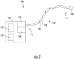
- the exemplary robotic arm assembly 100 depicted generally includes a base 102, a robotic arm 104, and a utility member 106.
- the base 102 generally includes an actuator pack 108 and a controller 110.
- the controller 110 is operably coupled to the actuator pack 108 for controlling operation of the robotic arm assembly 100.
- the controller 110 may be operably coupled to the utility member 106 and/or one or more sensors (not shown) attached to or embedded in the robotic arm 104 and/or utility member 106.
- the robotic arm 104 extends generally between a root end 112 and a distal end 114.
- the robotic arm 104 includes an attachment section 116 at the root end 112, with the attachment section 116, for the embodiment depicted, attached to the actuator pack 108 of the base 102. Additionally, the robotic arm 104 includes the utility member 106 at the distal end 114. The utility member 106 includes laser drill.
- the robotic arm 104 of the exemplary robotic arm assembly 100 depicted is generally formed of a plurality of links 118 and a plurality of joints 120, with the plurality of links 118 sequentially arranged and movably coupled to one another with the plurality of joints 120. At least certain of the plurality of links 118 are operable with the actuator pack 108, such that one or more actuators or motors (not shown) of the actuator pack 108 may control operation (such as a position and/or orientation) of the robotic arm 104. However, in other embodiments, any other suitable configuration may be provided for manipulating or otherwise controlling the plurality of links 118 of the robotic arm 104 of the exemplary robotic arm assembly 100.
- the base 102 includes one or more support structures 122 operable with the utility member 106 for assisting the utility member 106 and performing certain operations.
- the robotic arm 104 may define certain parameters to further enable it to reach the relatively remote positions within the interior of the turbomachine 16. More specifically, for the embodiment shown, the robotic arm 116 defines a length between the root end 112 in the distal end 114 of least about 91 cm (thirty-six (36) inches), such as at least about 122 cm (forty-eight (48) inches), such as at least about 152 cm (sixty (60) inches), such as up to about 1524 cm (600 inches).
- the robotic arm 116 defines a maximum diameter between the root end 120 and the distal end 122, which for the embodiment depicted is a maximum diameter of each of the individual segments 118 of the robotic arm 104, less than about 13 cm (five (5) inches).
- the maximum diameter of the robotic arm 104 may be less than about 8 cm (three (3) inches), such as less than about 6 cm (2.5 inches), such as less than about 3 cm (one (1) inch). Such may further allow the robotic arm 104 to reach the relatively remote locations within the interior of the turbomachine 16.
- a close-up, schematic view is provided of a turbine engine assembly 200 having a turbine engine 202 and a system 204 for performing an operation on a component 206 of the turbine engine 202.
- the turbine engine 202 may be a turbomachine of a gas turbine engine, such as the exemplary turbomachine 16 of the turbofan engine 10 described above with reference to Fig. 1 .
- the component 206 of the turbine engine 202 may be, e.g., one or more of an airfoil, a liner, or a shroud of the turbine engine 202.
- the component 206 is more particularly an airfoil.
- the component 206 may be one or more of a compressor rotor blade, a compressor stator vane, a turbine rotor blade, a turbine stator vane, an inlet guide vane, an outlet guide vane, an inner or outer turbine shroud, an inner or outer compressor shroud, a compressor section liner, a turbine section liner, an inner combustion chamber liner, an outer combustion chamber liner, etc.
- the component 206 may be positioned within an interior 208 of the turbine engine 202 (i.e., within an outer casing 210 of the turbine engine 202, similar to the exemplary outer casing 18 of the turbomachine 16 described above with reference to Fig. 1 ).
- the component 206 is exposed to a core air flowpath 212 of the turbine engine 202 (similar to the exemplary core air flowpath 37 of the exemplary turbomachine 16 described above with reference to Fig. 1 ).
- the component 206 generally includes a first side 214 positioned within the interior 208 of the turbine engine 202, and more specifically, exposed to the core air flowpath 212 of the turbine engine 202, and an opposite, second side 216 (not shown in Fig. 3 ).
- the second side 216 is also positioned within the interior 208 of the turbine engine 202, and more specifically, exposed to the core air flowpath 212 of the turbine engine 202.
- the component 206 may be positioned proximate one or more openings of the turbine engine 202.
- the exemplary turbine engine 202 within which the component 206 of Fig. 3 is positioned includes a first opening 218A and a second opening 218B.
- the first opening 218A and the second opening 218B extend through, e.g., the casing 210 of the turbine engine 202 and an outer shroud 219 surrounding the component 206.
- the first opening 218A and/or the second opening 218B may be, e.g., borescope openings (see, e.g., exemplary borescope openings 70 of Fig. 1 ).
- the turbine engine 10 may have any other suitable position and/or configuration of openings.
- the exemplary system 204 depicted in Fig. 3 includes a first robotic arm 220 and a second robotic arm 222, and more specifically, a first robotic arm assembly 224 including the first robotic arm 220 and a second robotic arm assembly 226 including the second robotic arm 222.
- the first robotic arm assembly 224 and second robotic arm assembly 226 may each be configured in a similar manner as the exemplary robotic arm assembly 100 described above with reference to Fig. 2 .
- the first robotic arm 220 of the first robotic arm assembly 224 extends between a first root end 228 and a first distal end 230, and the first robotic arm 220 generally includes a first utility member 232 positioned at the first distal end 230.
- the first robotic arm 220 is movable to the interior 208 of the engine to a location operably adjacent to the first side 214 of the component 206.
- the first robotic arm 220 is positioned through at least one of a plurality of openings of the turbine engine 202, and more specifically, through the first opening 218A of the turbine engine 202, such that the first utility member 232 of the first robotic arm 220 is positioned operably adjacent to the first side 214 of the component 206 during operation.
- the term "operably adjacent to" with reference to a utility member and a surface of the component refers to the utility member being positioned such that it may perform the operation for which it was designed on the component.
- the second robotic arm 222 of the second robotic arm assembly 226 extends between a second root end 234 and a second distal end 236, and the second robotic arm 222 generally includes a second utility member 238 positioned at the second distal end 236.
- the second robotic arm 222 is also movable to the interior 208 of the turbine engine 202 to facilitate the first utility member 232 and the second utility member 238 performing the operation on the component 206 of the turbine engine 202.
- the second robotic arm 222 is also positioned through at least one of a plurality of openings of the turbine engine 202, and more specifically, through the second opening 218B of the turbine engine 202, to facilitate the first and second utility members 232, 238 performing the operation on the component 206 of the turbine engine 202.
- first robotic arm assembly 224 and second robotic arm assembly 226 may be configured in a manner similar to the exemplary robotic arm assembly 100 described above with reference to, e.g., Fig. 2 .
- first robotic arm assembly 224 further includes a first base 240 with the first robotic arm 220 operably connected to the first base 240.
- the first base 240 includes one or more motors 242, or actuators (such as an actuator pack), for controlling the first robotic arm 220, and the first base 240 is configured for positioning outside of the interior 208 of the turbine engine 202.
- the second robotic arm assembly 226 further includes a second base 244 with the second robotic arm 222 operably connected to the second base 244.
- the second base 244 also includes one or more motors 246, or actuators (such as an actuator pack), for controlling the second robotic arm 222 and the second base 244 is configured for positioning outside of the interior 208 of the turbine engine 202. Accordingly, the first and second bases 240, 244 are each positioned outside of the interior 208 of the turbine engine 202 during operation of the system 204 (e.g., during the performance of the operation on the component 206 of the turbine engine 202 by the system 204).
- the first robotic arm assembly 224, the second robotic arm assembly 226, or both may have any other suitable configuration.
- the first base 240 of the first robotic arm assembly 224 is depicted as being positioned physically separate from the second base 244 of the second robotic arm assembly 226, in other exemplary embodiments, the first base 240 and second base 244 may be integrated as a single, contained unit.
- one or both of the first robotic arm 220 and second robotic arm 222 may be constructed in any suitable manner, and one or both of the first base 240 and second base 244 may have any other suitable structure for controlling such robotic arms (e.g., any suitable motor/actuator configuration, etc.).
- the system 204 includes a controller 246.
- the exemplary controller 246 is operably connected to the first base 240 of the first robotic arm assembly 224 and the second base 244 of the second robotic arm assembly 226 for controlling the first robotic arm 220 and the second robotic arm 222.
- the controller 246 may be positioned, or otherwise integrated into, the first base 240 of the first robotic arm assembly 224, the second base 244 of the second robotic arm assembly 226, or both. Additionally, or alternatively, the controller 246 may be integrated into, and/or operable with, any other suitable system.
- the controller 246 generally includes a network interface 248.
- the network interface 248 may be operable with any suitable wired or wireless communications network for communicating data with other components of, e.g., the robotic arm assembly 100, and/or other components or systems not depicted.
- the network interface 248 utilizes a wireless communication network 250 to communicate data with other components.
- the controller 246 is operably coupled to the first base 240 of the first robotic arm assembly 224 and the second base 244 of the second robotic arm assembly 226.
- the controller 246 may be operably coupled to the one or more motors 242 of the first base 240 and/or the one or more motors 246 of the second base 244. In such a manner, the controller 246 may control operation of the first robotic arm 220 and the second robotic arm 222.
- the network interface 248 utilizes the wireless communication network 250 for the embodiment of Fig. 3
- the network interface 248 may instead utilize a wired communication network, or a combination of wired and wireless communication networks.
- the controller 246 further includes one or more processors 252 and memory 254.
- the memory 254 stores data 256 accessible by the one or more processors 252.
- the one or more processor(s) 252 can include any suitable processing device, such as a microprocessor, microcontroller, integrated circuit, logic device, and/or other suitable processing device.
- the one or more memory device(s) 254 can include one or more computer-readable media, including, but not limited to, non-transitory computer-readable media, RAM, ROM, hard drives, flash drives, and/or other memory devices.
- the data 256 may include instructions that when executed by the one or more processors 252 cause the system 204 to perform functions.
- the instructions within the data 256 can be any set of instructions that when executed by the one or more processor(s) 252, cause the one or more processor(s) 252 to perform operations.
- the instructions within the data 256 can be software written in any suitable programming language or can be implemented in hardware. Additionally, and/or alternatively, the instructions can be executed in logically and/or virtually separate threads on processor(s) 252.
- the memory device(s) 254 can further store other data 256 that can be accessed by the processor(s) 252.
- Fig. 4 a close-up, schematic view of the exemplary system 204 of Fig. 3 is depicted.
- the operation being performed by the system 204 on the component 206 is a physical operation on the component (i.e., physically modifying the component). More particularly, for the embodiment depicted, the operation is a material removal operation, and more specifically still is a drilling operation.
- drilling operation refers generally to any operation used to make a hole in or through a component, whether the hole is circular in cross-section or defines some other shape.
- the first utility member 232 of the first robotic arm 220 includes a mechanical drill having a drill bit 258.
- the first utility member 232 may be configured to rotate the drill (and drill bit 258) to drill a hole 260 in or through the component 206, i.e., from the first side 214 of the component 206 towards or to the second side 216 of the component 206.
- the hole 260 may be, e.g. a cooling hole, or may be provided for any other purpose. Additionally, it will be appreciated that the hole 260 may be a new hole drilled by the mechanical drill of the first utility member 232, or alternatively, may be an existing hole that is, e.g. clogged, needs to be widened, etc.
- the second utility member 238 includes at least one of a container or a suction member. More specifically, for the embodiment of Fig. 4 , the second utility member 238 includes a container 262 for positioning over the hole 260 on the second side 216 of the component 206 to capture or otherwise contain debris and/or other materials resulting from the operation of the mechanical drill of the first utility member 232 to drill the hole 260 in the component 206. More particularly, for the embodiment of Fig. 4 , the container 262 is positioned completely around/over the hole 260 on the second side 216 of the component 206, contacting the second side 216 of the component 206. However, in other embodiments, the container 262 may instead be positioned elsewhere to capture debris from the drilling operation.
- the container 262 may be positioned underneath the mechanical drill of the first utility member 232 on the first side 214 of the component 206 to catch debris falling from the mechanical drill.
- the container 262 may be positioned underneath the opening on the second side 216 of the component 206 of the hole 260 being drilled by the mechanical drill to catch the debris when the mechanical drill breaks through the second side 216 of the component 206, or otherwise completes drilling operations of the hole 260.
- any other suitable component 206 or feature may be provided for catching the debris resulting from the drilling operation.
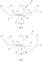
- a close-up, schematic view is provided of a system 204 in accordance with another exemplary embodiment of the present disclosure.
- the exemplary system 204 of Fig. 5 may be configured in substantially the same manner as the exemplary system 204 described above with reference to Fig. 4 .
- a second utility member 238 of a second robotic arm 222 instead includes a suction member 264.
- the suction member 264 generally defines a suction nozzle for capturing debris or other particles resulting from the drilling operation.
- the second robotic arm 222 may include one or more vacuum lines (not shown; e.g., supported by support structures 122, see Fig. 2 ) extending therethrough in airflow communication with the suction member 264 for providing a desired suction to the suction member.
- any other suitable component 206 or feature may be provided for facilitating the drilling operation.
- a close-up, schematic view is provided of a system 204 in accordance with yet another exemplary embodiment of the present disclosure.
- the exemplary system 204 of Fig. 6 may be configured in substantially the same manner as exemplary system 204 described above with reference to Fig. 4 .
- the first utility member 232 includes a laser drill 266.
- the laser drill 266 of the first utility member 232 is similarly configured to be positioned operably adjacent to the first side 214 of the component 206, and oriented towards the first side 214 of the component 206 during drilling operations.
- the laser drill 266 of the first utility member 232 defines a line of sight of access to the first side 214 of the component 206, and is separated by a distance of no more than a distance at which the laser drill 266 may effectively operate (i.e., drill into, or through, the component 206), such that it may drill a hole 260 in the component 206 at a desired position and orientation into/ through the component 206.
- the laser drill 266 is generally configured to direct a laser beam 268 towards the component 206 to drill the hole 260 therethrough.
- the laser drill 266 may be configured as any suitable laser drill.
- the laser drill may be a Nd:YAG laser drill or any other suitable laser drill.
- a second utility member 238 of a second robotic arm 222 positioned at a second distal end 236 thereof may not be configured as at least one of a container ( Fig. 4 ) or a suction member ( Fig. 5 ).
- the second utility member 238 of the second robotic arm 222 includes a laser beam receiver 270.
- the laser beam receiver 270 of the second utility member 238 is aligned with an axis 272 of the laser beam 268 from the laser drill 266 of the first utility member 232 during drilling operations of the system 204.
- the laser beam receiver 270 may be any suitable material or component capable of absorbing or dissipating a laser beam 268 from the laser drill 266 after such laser beam 268 has broken through the second side 216 of the component 206, preventing an amount of potential damage to various other components within the interior 208 of the turbine engine 202.
- the laser beam receiver 270 may also be referred to as a back strike protection member or a "beam dump.”
- the laser beam receiver 270 may be a plate comprising a metal or other sufficiently robust material capable of withstanding drilling from the laser beam 268 of the laser drill 266 for at least a minimal amount of time. It will be appreciated, however, that in other embodiments, the laser beam receiver 270 may have any other suitable configuration for performing the functions described herein.
- the laser beam receiver 270 may further include suction features (similar to the suction member 264 discussed above) for removing cutting debris (e.g., vapor, hot liquid droplets, etc.) from the environment to prevent damage to adjacent surfaces, and/or air blowing features, such as an air curtain or other wide jet of pressurized air to deflect debris to a relatively less sensitive location.
- suction features similar to the suction member 264 discussed above
- air blowing features such as an air curtain or other wide jet of pressurized air to deflect debris to a relatively less sensitive location.
- the laser beam receiver 270 may include one or more sensors coupled thereto, operable therewith, and/or embedded therein.
- the laser beam receiver 270 includes a sensor 274 coupled thereto.
- the sensor 274 may be configured to sense when the laser beam 268 of the laser drill 266 contacts the laser beam receiver 270. In such a manner, the sensor 274 may be capable of sensing data indicative of a breakthrough of the laser beam 268 through the component 206.
- the sensor 274 may be operably coupled to the controller 246 through, e.g., the wireless communication network 250 (see Fig. 3 ).
- the sensor 274 may be any suitable sensor for sensing data indicative of the laser beam 268 contacting the laser beam receiver 270.
- the sensor 274 may be one or more of, e.g., a temperature sensor, an accelerometer, an optical sensor, and acoustic sensor, etc.
- each of the exemplary systems 204 of Figs. 7 and 8 may each be configured in substantially the same manner as exemplary system 204 described above with reference to Fig. 4 .
- each of the exemplary systems 204 of Figs. 7 and 8 includes a first robotic arm 220 including a first utility member 232 positioned at a first distal end 230 of the first robotic arm 220 and a second robotic arm 222 including a second utility member 238 positioned at a second distal end 236 of the second robotic arm 222.
- the operation performed by the system 204 is a welding operation.
- the first utility member 232 includes an electrode 276 and the second utility member 238 includes an electrical connector 278 configured for electrical connection to the component 206.
- the second utility member 238, or rather, the electrical connector 278 of the second utility member 238, is configured to contact the component 206.
- the system 204 may provide for an electrical path through the component 206 during welding operations that avoids any sensitive components, such as bearings, that may otherwise be damaged by electrical paths extending therethrough.
- the electrical connector 278 of the second utility member 238 is directly contacting the actual component 206, in other embodiments, the electrical connector 278 may instead contact any other suitable components of the turbine engine 202 capable of providing an electrical connection with the component 206 without any substantial risk of the electrical path extending through undesirable, sensitive components.
- first robotic arm 220 and second robotic arm 222 may include additional components, features, etc.
- the system 204 may be configured for gas metal arc welding, tungsten inert gas welding, arc welding, etc.
- one or both of the first robotic arm 220 and second robotic arm 222 may include a gas line, or alternatively, an additional robotic arm (not shown) may be included with a gas line, to provide a working gas for the welding.
- the operation performed by the system 204 is, again, a drilling operation.
- the first utility member 232 includes an electric discharge machine tool 280 positioned operably adjacent to the first side 214 of the component 206, and oriented towards the first side 214 of the component 206 during drilling operations.
- the electric discharge machine tool 280 of the first utility member 232 is positioned in a relatively close proximity to the first side 214 of the component 206 such that it may drill a hole in the component 206 at a desired position and orientation through the component 206.
- the electric discharge machine tool 280 may be a tool electrode configured to discharge a current to the first side 214 of the component 206 (or along a hole through the component 206), across a discharge gap 282 defined with the first side 214 of the component 206.
- the second utility member 238 includes an electrical connector 278 configured for electrical connection to the component 206. More specifically, for the embodiment of Fig. 8 , the electrical connector 278 of the second utility member 238 is configured to contact the component 206 to create a charge differential between, e.g., the tool electrode 276 of the electric machine tool of the first utility member 232 and the component 206.
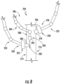
- the exemplary system 204 of Fig. 8 further includes a third robotic arm 284 of a third robotic arm assembly 286.
- the third robotic arm assembly 286, and third robotic arm 284 may also be configured in substantially the same manner as the exemplary robotic arm assembly 100 described above with reference to Fig. 2 .
- the third robotic arm 284 extends generally between a root end (not shown) and a distal end 288 and includes a third utility member 290 positioned at the third distal end 288.
- the third utility member 290 includes a dielectric fluid nozzle 292 for providing a dielectric fluid to a location between the first utility member 232 (i.e., the electric discharge machine tool 280 for the embodiment depicted) and the component 206. Providing the dielectric fluid may facilitate the electric discharge machine tooling by the system 204.
- exemplary system 204 depicted in Fig. 8 is the only system 204 described herein as including three robotic arms for facilitating the operations, in other exemplary embodiments, one or more of the embodiments described above with reference to, e.g., Figs. 3 through 7 may additionally include a third robotic arm, and optionally may include any other suitable number of robotic arms.
- electric discharge machine operations are depicted using three separate robotic arms, in other exemplary embodiments, the features and functionality of one of the exemplary robotic arms depicted may instead be integrated into one of the other robotic arms, such that only two robotic arms are utilized to provide electric discharge machine tooling.
- any other suitable physical operations may be performed using a system 204 in accordance with one or more the exemplary embodiments described herein.
- the operation may additionally, or alternatively, include one or more cutting operations, brazing operations, coating or slurry repair operations, etc.
- the operations may be a coating repair process (such as a thermal barrier coating repair process), whereby a first robotic arm is operable to remove at least a portion of an existing coating and a second robotic arm is operable to apply a new coating.
- the operation may be a slurry repair operation for a ceramic matrix composite (CMC) component, such as a CMC liner , CMC shroud, etc.
- CMC ceramic matrix composite
- a first robotic arm may be operable to apply a slurry and a second robotic arm is operable to cure the slurry. Additionally, one or both of the first and second robotic arms (or additional robotic arms) may be operable to contour and/or level the slurry.
- the term "facilitate” may refer to performing a function simultaneously (e.g., first and second robotic arms working together simultaneously to perform the operation), or alternatively may refer to performing functions sequentially.
- any other suitable non-physical operations may be performed by the system.
- the operations may be cleaning operations (such as sandblasting, pressure washing, steam washing), etc.
- the exemplary system 204 described herein is depicted performing operations on a turbine engine 202, in other exemplary embodiments, the system 204 may instead be utilized to perform operations on any other suitable engine, such as a rotary engine. Further, the system 204 described herein may additionally, or alternatively, may be utilized outside of the context of an engine in, e.g., relatively dangerous environments to perform operations. For example, in certain embodiments, the system 204 may be utilized within the oil and gas industry to, e.g., weld, cut, drill, etc. in, e.g., explosive atmospheres. Further, still, in certain embodiments, the system 204 may be utilized in the nuclear industry to, e.g., drill, cut, weld, etc. in a reactor or other container.
- a flow diagram of a method 300 for performing an operation on a component of an engine in accordance with an exemplary aspect of the present disclosure is provided.
- the exemplary method 300 may utilize one or more of the exemplary systems described above.
- the component includes a first side positioned within an interior of the engine.
- the exemplary method 300 generally includes at (302) positioning a first robotic arm including a first utility member at a first distal end within the interior of the engine to a location operably adjacent to the first side of the component.
- the engine defines a plurality of openings.
- the plurality of openings may include one or more of a borescope opening, a fuel nozzle opening, an igniter opening, an inlet opening, an exhaust opening, etc.
- positioning the first robotic arm within the interior of the engine at (302) includes at (304) extending the first robotic arm through a first opening of the engine.
- the exemplary method 300 further includes at (306) positioning a second robotic arm including a second utility member at a second distal end within the interior of the engine. Similarly, for the exemplary aspect depicted, positioning the second robotic arm within the interior of the engine at (306) includes at (308) extending the second robotic arm through a second opening of the engine.
- the exemplary method 300 includes at (310) performing the operation on the component of the engine utilizing the first utility member of the first robotic arm and the second utility member of the second robotic arm within the interior of the engine.
- Performing the operation on the component of the engine at (310) includes at (312) performing a drilling operation on the component of the engine.
Landscapes
- Engineering & Computer Science (AREA)
- Mechanical Engineering (AREA)
- Robotics (AREA)
- Human Computer Interaction (AREA)
- General Engineering & Computer Science (AREA)
- Manufacturing & Machinery (AREA)
- Transportation (AREA)
- Aviation & Aerospace Engineering (AREA)
- Manipulator (AREA)
- Structures Of Non-Positive Displacement Pumps (AREA)
Claims (15)
- Système (204) permettant de mettre en oeuvre une opération sur un composant (206) d'un moteur, le composant (206) comportant un premier côté (214) positionné au sein d'un intérieur (208) du moteur, le système comprenant :un premier bras robotisé (220) définissant une première extrémité distale (230) et comportant un premier élément d'utilité (232) positionné au niveau de la première extrémité distale (230), le premier bras robotisé (220) pouvant être déplacé vers l'intérieur (208) du moteur jusqu'à une localisation opérationnellement adjacente au premier côté (214) du composant (206) ; etun second bras robotisé (222) définissant une seconde extrémité distale (236) et comportant un second élément d'utilité (238) positionné au niveau de la seconde extrémité distale (236), le second bras robotisé (222) pouvant également être déplacé vers l'intérieur (208) du moteur pour aider les premier et second éléments d'utilité (232, 238) à mettre en oeuvre l'opération sur le composant (206) du moteur,dans lequel l'opération est une opération de forage, etdans lequel le premier élément d'utilité (232) comporte une foreuse laser (266) conçue pour une orientation en direction du premier côté (214) du composant (206), et caractérisé en ce que le second élément d'utilité (238) comporte un récepteur de faisceau laser (270).
- Système selon la revendication 1, dans lequel le moteur est un moteur à turbine à gaz, et dans lequel le composant est l'un parmi un profil aérodynamique, une chemise ou un carénage.
- Système selon la revendication 1, dans lequel le premier bras robotisé (220) est relié opérationnellement à une première base (240), dans lequel la première base (240) comporte un ou plusieurs mécanismes moteurs (242) permettant de commander le premier bras robotisé (220), dans lequel la première base (240) est conçue pour un positionnement à l'extérieur de l'intérieur (208) du moteur, dans lequel le second bras robotisé (222) est relié opérationnellement à une seconde base (244), dans lequel la seconde base (244) comporte un ou plusieurs mécanismes moteurs permettant de commander le second bras robotisé (222), et dans lequel la seconde base (244) est conçue pour un positionnement à l'extérieur de l'intérieur (208) du moteur.
- Système selon la revendication 3, comprenant en outre :
un organe de commande (246) relié opérationnellement à la première base (240) et à la seconde base (244) permettant de commander le premier bras robotisé (220) et le second bras robotisé (222). - Système selon la revendication 1, dans lequel le récepteur de faisceau laser (270) est aligné avec un axe (272) d'un faisceau laser (268) provenant de la foreuse laser (266) pendant l'opération de forage du système (204).
- Système selon la revendication 1, dans lequel le récepteur de faisceau laser (270) est une plaque comprenant un métal ou un autre matériau capable de supporter un forage par un faisceau laser (268) de la foreuse laser 266 pendant au moins une quantité minimale de temps.
- Système selon la revendication 1, dans lequel le récepteur de faisceau laser (270) comporte des fonctionnalités d'aspiration permettant de retirer des débris de coupe.
- Système selon la revendication 1, dans lequel le récepteur de faisceau laser (270) comporte des fonctionnalités de soufflage d'air pour dévier des débris de coupe.
- Système selon la revendication 1, dans lequel le récepteur de faisceau laser (270) comporte un ou plusieurs capteurs (274) couplés à celui-ci, opérationnels avec celui-ci, et/ou intégrés dans celui-ci, le ou les capteurs (274) étant configurés pour capter lorsqu'un faisceau laser (268) de la foreuse laser (266) vient en contact avec le récepteur de faisceau laser (270).
- Système selon la revendication 9, dans lequel le ou les capteurs (274) comprennent un ou plusieurs parmi un capteur de température, un accéléromètre, un capteur optique ou un capteur acoustique.
- Procédé (300) permettant de mettre en oeuvre une opération sur un composant (206) d'un moteur, le composant (206) comportant un premier côté (214) positionné au sein d'un intérieur (208) du moteur, le procédé (300) comprenant :le positionnement (302) d'un premier bras robotisé comportant un premier élément d'utilité au niveau d'une première extrémité distale au sein de l'intérieur du moteur au niveau d'une localisation opérationnellement adjacente au premier côté du composant ;le positionnement (306) d'un second bras robotisé comportant un second élément d'utilité au niveau d'une seconde extrémité distale au sein de l'intérieur du moteur ; etla mise en oeuvre (310) de l'opération sur le composant du moteur en utilisant le premier élément d'utilité du premier bras robotisé et le second élément d'utilité du second bras robotisé au sein de l'intérieur du moteur ;dans lequel la mise en oeuvre de l'opération sur le composant du moteur comprend la mise en oeuvre d'une opération de forage sur le composant du moteur, dans lequel l'opération de forage est mise en oeuvre avec une foreuse laser en guise de premier élément d'utilité et avec un récepteur de faisceau laser en guise de second élément d'utilité.
- Procédé selon la revendication 11, dans lequel le positionnement du premier bras robotisé au sein de l'intérieur du moteur comprend l'extension du premier bras robotisé à travers une première ouverture du moteur, et dans lequel le positionnement du second bras robotisé au sein de l'intérieur du moteur comprend l'extension du second bras robotisé à travers une seconde ouverture du moteur.
- Procédé selon la revendication 11, comprenant en outre l'alignement du récepteur de faisceau laser (270) avec un axe (272) d'un faisceau laser (268) provenant de la foreuse laser (266) pendant les opérations de forage.
- Procédé selon la revendication 11, comprenant en outre le fait de retirer des débris de coupe à l'aide d'une fonctionnalité d'aspiration du récepteur (270).
- Procédé selon la revendication 11, comprenant en outre le fait de dévier des débris de coupe à l'aide d'une fonctionnalité de soufflage d'air du récepteur (270).
Priority Applications (1)
| Application Number | Priority Date | Filing Date | Title |
|---|---|---|---|
| EP24201736.6A EP4459108A3 (fr) | 2018-06-14 | 2019-06-13 | Système et procédé pour effectuer des opérations sur un moteur |
Applications Claiming Priority (2)
| Application Number | Priority Date | Filing Date | Title |
|---|---|---|---|
| US16/008,510 US10988268B2 (en) | 2018-06-14 | 2018-06-14 | System and method for performing operations on an engine |
| PCT/US2019/037026 WO2019241541A1 (fr) | 2018-06-14 | 2019-06-13 | Système et procédé d'exécution d'opérations sur un moteur |
Related Child Applications (2)
| Application Number | Title | Priority Date | Filing Date |
|---|---|---|---|
| EP24201736.6A Division EP4459108A3 (fr) | 2018-06-14 | 2019-06-13 | Système et procédé pour effectuer des opérations sur un moteur |
| EP24201736.6A Division-Into EP4459108A3 (fr) | 2018-06-14 | 2019-06-13 | Système et procédé pour effectuer des opérations sur un moteur |
Publications (3)
| Publication Number | Publication Date |
|---|---|
| EP3807501A1 EP3807501A1 (fr) | 2021-04-21 |
| EP3807501B1 true EP3807501B1 (fr) | 2024-11-27 |
| EP3807501B8 EP3807501B8 (fr) | 2025-01-01 |
Family
ID=67480276
Family Applications (2)
| Application Number | Title | Priority Date | Filing Date |
|---|---|---|---|
| EP24201736.6A Pending EP4459108A3 (fr) | 2018-06-14 | 2019-06-13 | Système et procédé pour effectuer des opérations sur un moteur |
| EP19746204.7A Active EP3807501B8 (fr) | 2018-06-14 | 2019-06-13 | Système et procédé d'exécution d'opérations sur un moteur |
Family Applications Before (1)
| Application Number | Title | Priority Date | Filing Date |
|---|---|---|---|
| EP24201736.6A Pending EP4459108A3 (fr) | 2018-06-14 | 2019-06-13 | Système et procédé pour effectuer des opérations sur un moteur |
Country Status (6)
| Country | Link |
|---|---|
| US (1) | US10988268B2 (fr) |
| EP (2) | EP4459108A3 (fr) |
| CN (1) | CN112292512B (fr) |
| CA (2) | CA3101621C (fr) |
| SG (1) | SG11202011546XA (fr) |
| WO (1) | WO2019241541A1 (fr) |
Families Citing this family (1)
| Publication number | Priority date | Publication date | Assignee | Title |
|---|---|---|---|---|
| CN111531202B (zh) * | 2020-05-12 | 2021-09-03 | 航天特种材料及工艺技术研究所 | 一种飞机蒙皮装配孔的定位方法、加工方法 |
Citations (2)
| Publication number | Priority date | Publication date | Assignee | Title |
|---|---|---|---|---|
| EP2116340A1 (fr) * | 2008-05-08 | 2009-11-11 | The Boeing Company | Fonctionnement robotique synchrone sur une structure ayant un espace confiné |
| EP3222751A1 (fr) * | 2016-03-22 | 2017-09-27 | General Electric Company | Vessies gonflables de turbine à gaz in situ pour réparation sur l'aile |
Family Cites Families (50)
| Publication number | Priority date | Publication date | Assignee | Title |
|---|---|---|---|---|
| US4260941A (en) | 1975-10-28 | 1981-04-07 | Unimation, Inc. | Programmable automatic assembly system |
| US4267424A (en) * | 1978-05-22 | 1981-05-12 | Nissan Motor Company, Limited | Spot welding machine for heavy-duty operations on surface contoured workpieces |
| US5608847A (en) | 1981-05-11 | 1997-03-04 | Sensor Adaptive Machines, Inc. | Vision target based assembly |
| JPH01274981A (ja) * | 1988-04-26 | 1989-11-02 | Fuji Heavy Ind Ltd | 工業用ロボットの位置補正装置 |
| FR2647696B1 (fr) | 1989-06-06 | 1991-09-27 | Dassault Avions | Ensemble d'outillage pour rivetage de pieces |
| US5318254A (en) | 1991-06-28 | 1994-06-07 | Conceptual Solutions, Inc. | Aircraft maintenance robot |
| SE515396C2 (sv) * | 1999-05-12 | 2001-07-30 | Abb Ab | En svivel för flexibel transport av en fluid |
| GB0020461D0 (en) * | 2000-08-18 | 2000-10-11 | Oliver Crispin Consulting Ltd | Improvements in and relating to the robotic positioning of a work tool to a sensor |
| US6442451B1 (en) * | 2000-12-28 | 2002-08-27 | Robotic Workspace Technologies, Inc. | Versatile robot control system |
| US20050224474A1 (en) | 2002-10-17 | 2005-10-13 | Kilburn Chris A | Method and apparatus for removing a thermal barrier coating from a power generation component |
| KR100494938B1 (ko) * | 2003-07-07 | 2005-06-13 | 현대자동차주식회사 | 클램핑 장치 |
| EP1704073B1 (fr) * | 2004-01-14 | 2008-04-02 | Bayerische Motoren Werke Aktiengesellschaft | Transfert d'au moins un reglage, relatif aux personnes, d'un vehicule |
| US7509735B2 (en) | 2004-04-22 | 2009-03-31 | Siemens Energy, Inc. | In-frame repairing system of gas turbine components |
| DE102004037355A1 (de) | 2004-07-30 | 2006-03-23 | Patent-Treuhand-Gesellschaft für elektrische Glühlampen mbH | Goniophotometer |
| DE102004050426B4 (de) * | 2004-10-15 | 2010-05-20 | Mtu Aero Engines Gmbh | Verfahren und System zur Winkelsynchronisation |
| ITTO20050513A1 (it) * | 2005-07-25 | 2007-01-26 | Comau Spa | Cella per l'assemblaggio automatizzato di componenti e/o l'esecuzione di operazioni su un pezzo in una linea di produzione industriale, e robot manipolatore utilizzato in tale cella. |
| US7394040B2 (en) * | 2006-03-31 | 2008-07-01 | General Electric Company | Electromachining process and apparatus |
| DE102006020924B4 (de) | 2006-05-05 | 2009-03-19 | Thyssenkrupp Drauz Nothelfer Gmbh | Vorrichtung zum Bearbeiten von Bauteilen, insbesondere einer Kraftfahrzeugkarosserie |
| ES2325433B1 (es) * | 2006-07-31 | 2010-06-21 | Airbus Operations, S.L. | Robot trepador equipado con una unidad de trabajo, y equipo de gobierno de tales robots trepadores. |
| US8127423B2 (en) | 2007-10-05 | 2012-03-06 | Hirotec America, Inc. | Roller hemming system |
| GB2455804A (en) * | 2007-12-21 | 2009-06-24 | Oliver Crispin Robotics Ltd | A robotic arm for use with a rotary machine |
| US8157155B2 (en) * | 2008-04-03 | 2012-04-17 | Caterpillar Inc. | Automated assembly and welding of structures |
| US8286320B2 (en) | 2008-09-18 | 2012-10-16 | Automatic Handling International | Apparatus and method for the robotic plugging/unplugging of rolls |
| JP2010076006A (ja) * | 2008-09-24 | 2010-04-08 | Mitsubishi Heavy Ind Ltd | 加工ラインモジュール及び加工設備 |
| US8927897B2 (en) | 2010-11-17 | 2015-01-06 | Rolls-Royce Corporation | Laser maintenance tool |
| US8636449B2 (en) * | 2011-04-27 | 2014-01-28 | General Electric Company | Inner casing vacuum system for a gas turbine engine casing |
| GB2504612B (en) | 2011-05-09 | 2014-09-24 | Rolls Royce Plc | An apparatus for supporting a tool in an assembled apparatus |
| PL2554459T3 (pl) | 2011-08-01 | 2017-07-31 | Comau Spa | System montażu części składowej na konstrukcji nadwozia pojazdu samochodowego |
| US9349234B2 (en) * | 2012-03-14 | 2016-05-24 | Autoconnect Holdings Llc | Vehicle to vehicle social and business communications |
| GB201215989D0 (en) * | 2012-09-07 | 2012-10-24 | Rolls Royce Plc | A boroscope and a method of processing a component within an assembled apparatus using a boroscope |
| US20140138358A1 (en) * | 2012-11-21 | 2014-05-22 | General Electric Company | Component repair arrangement and method |
| US20150066246A1 (en) * | 2013-08-30 | 2015-03-05 | U-Me Holdings LLC | Making a user's information available in a vehicle |
| DE102013220798A1 (de) * | 2013-10-15 | 2015-04-16 | Kuka Laboratories Gmbh | Verfahren zum Handhaben von Objekten mittels wenigstens zweier Industrieroboter, und zugehöriger Industrieroboter |
| US10022867B2 (en) * | 2014-11-11 | 2018-07-17 | X Development Llc | Dynamically maintaining a map of a fleet of robotic devices in an environment to facilitate robotic action |
| US10041371B1 (en) * | 2015-02-06 | 2018-08-07 | Siemens Energy, Inc. | In-situ measurement of blade tip-to-shroud gap in turbine engine |
| US9514653B2 (en) * | 2015-04-09 | 2016-12-06 | Elwha Llc | Systems, methods, and devices for providing assistance to an unmanned aerial vehicle |
| US9789549B2 (en) * | 2015-07-07 | 2017-10-17 | The Boeing Company | Robotic system and drilling end effector for robotic system |
| US10252421B2 (en) * | 2015-10-06 | 2019-04-09 | Mtm Robotics Llc | Self-contained modular manufacturing tool |
| US10232897B2 (en) * | 2015-10-16 | 2019-03-19 | The Boeing Company | Walking robot |
| DE102016004788A1 (de) * | 2016-04-20 | 2017-10-26 | Kastanienbaum GmbH | Verfahren zur Herstellung eines Roboters und Vorrichtung zur Durchführung dieses Verfahrens |
| US10268177B2 (en) * | 2016-05-19 | 2019-04-23 | The Boeing Company | Method and apparatus of coordinating independent automated systems |
| US9981382B1 (en) * | 2016-06-03 | 2018-05-29 | X Development Llc | Support stand to reorient the grasp of an object by a robot |
| JP6811635B2 (ja) * | 2017-02-10 | 2021-01-13 | 川崎重工業株式会社 | ロボットシステム及びその制御方法 |
| JP6470336B2 (ja) * | 2017-03-27 | 2019-02-13 | ファナック株式会社 | 工作機械システムおよび移動方法 |
| JP6705976B2 (ja) * | 2017-05-11 | 2020-06-03 | 株式会社安川電機 | ロボット、ロボットの制御方法、ワークの製造方法 |
| GB201713277D0 (en) * | 2017-08-18 | 2017-10-04 | Rolls Royce Plc | Hyper-redundant manipulators |
| CN109866220B (zh) * | 2017-12-05 | 2021-07-23 | 财团法人工业技术研究院 | 机械手臂的校正装置及其校正方法 |
| US10967749B2 (en) * | 2017-12-29 | 2021-04-06 | Irobot Corporation | Electrostatic discharge systems for autonomous mobile robots |
| US11203318B2 (en) * | 2018-06-18 | 2021-12-21 | Waymo Llc | Airbag extension system |
| US11046273B2 (en) * | 2019-01-22 | 2021-06-29 | GM Global Technology Operations LLC | Seat belt status determining system and method |
-
2018
- 2018-06-14 US US16/008,510 patent/US10988268B2/en active Active
-
2019
- 2019-06-13 WO PCT/US2019/037026 patent/WO2019241541A1/fr not_active Ceased
- 2019-06-13 EP EP24201736.6A patent/EP4459108A3/fr active Pending
- 2019-06-13 CN CN201980038795.6A patent/CN112292512B/zh active Active
- 2019-06-13 CA CA3101621A patent/CA3101621C/fr active Active
- 2019-06-13 CA CA3253229A patent/CA3253229A1/fr active Pending
- 2019-06-13 SG SG11202011546XA patent/SG11202011546XA/en unknown
- 2019-06-13 EP EP19746204.7A patent/EP3807501B8/fr active Active
Patent Citations (2)
| Publication number | Priority date | Publication date | Assignee | Title |
|---|---|---|---|---|
| EP2116340A1 (fr) * | 2008-05-08 | 2009-11-11 | The Boeing Company | Fonctionnement robotique synchrone sur une structure ayant un espace confiné |
| EP3222751A1 (fr) * | 2016-03-22 | 2017-09-27 | General Electric Company | Vessies gonflables de turbine à gaz in situ pour réparation sur l'aile |
Also Published As
| Publication number | Publication date |
|---|---|
| CA3253229A1 (fr) | 2025-02-24 |
| CA3101621A1 (fr) | 2019-12-19 |
| CN112292512A (zh) | 2021-01-29 |
| WO2019241541A1 (fr) | 2019-12-19 |
| EP4459108A3 (fr) | 2025-01-29 |
| SG11202011546XA (en) | 2020-12-30 |
| EP3807501B8 (fr) | 2025-01-01 |
| US20190382138A1 (en) | 2019-12-19 |
| CN112292512B (zh) | 2023-04-11 |
| CA3101621C (fr) | 2025-12-16 |
| EP3807501A1 (fr) | 2021-04-21 |
| EP4459108A2 (fr) | 2024-11-06 |
| US10988268B2 (en) | 2021-04-27 |
Similar Documents
| Publication | Publication Date | Title |
|---|---|---|
| EP3208432B1 (fr) | Système et procédé de réparation d'un matériau abradable | |
| CN113803123B (zh) | 检查和维修工具 | |
| US10822997B2 (en) | Inspection tool and method | |
| EP3165712A1 (fr) | Moteur à turbine à gaz présentant une surface de régulation de flux avec un conduit de refroidissement | |
| US10436068B2 (en) | Flowpath contouring | |
| JP2017141830A (ja) | ターボ機械の流路表面用のリブレット | |
| US10495309B2 (en) | Surface contouring of a flowpath wall of a gas turbine engine | |
| JP7516399B2 (ja) | Tbcシート破砕の程度の制御 | |
| US20190337102A1 (en) | Interlocking Stage of Airfoils | |
| CN108386869B (zh) | 用于燃气涡轮发动机的燃烧器组件 | |
| US11377957B2 (en) | Gas turbine engine with a diffuser cavity cooled compressor | |
| EP3807501B1 (fr) | Système et procédé d'exécution d'opérations sur un moteur | |
| EP3748133B1 (fr) | Joint à air extérieur d'aube résistant à la fatigue | |
| US12000296B2 (en) | Seal for a rotor | |
| EP3667016B1 (fr) | Aube de soufflante comportant un dispositif de mesure intégré pour régler la pression du gaz à l'intérieur de l'aube de soufflante et procedé associé de fabrication d'une aube de soufflante | |
| CN108999644B (zh) | 涡轮发动机的冷却部件 | |
| EP3163015A1 (fr) | Réparation de buse de puissance avec matériel de refroidissement installé |
Legal Events
| Date | Code | Title | Description |
|---|---|---|---|
| STAA | Information on the status of an ep patent application or granted ep patent |
Free format text: STATUS: UNKNOWN |
|
| STAA | Information on the status of an ep patent application or granted ep patent |
Free format text: STATUS: THE INTERNATIONAL PUBLICATION HAS BEEN MADE |
|
| PUAI | Public reference made under article 153(3) epc to a published international application that has entered the european phase |
Free format text: ORIGINAL CODE: 0009012 |
|
| STAA | Information on the status of an ep patent application or granted ep patent |
Free format text: STATUS: REQUEST FOR EXAMINATION WAS MADE |
|
| 17P | Request for examination filed |
Effective date: 20201112 |
|
| AK | Designated contracting states |
Kind code of ref document: A1 Designated state(s): AL AT BE BG CH CY CZ DE DK EE ES FI FR GB GR HR HU IE IS IT LI LT LU LV MC MK MT NL NO PL PT RO RS SE SI SK SM TR |
|
| AX | Request for extension of the european patent |
Extension state: BA ME |
|
| DAV | Request for validation of the european patent (deleted) | ||
| DAX | Request for extension of the european patent (deleted) | ||
| STAA | Information on the status of an ep patent application or granted ep patent |
Free format text: STATUS: EXAMINATION IS IN PROGRESS |
|
| 17Q | First examination report despatched |
Effective date: 20221213 |
|
| GRAP | Despatch of communication of intention to grant a patent |
Free format text: ORIGINAL CODE: EPIDOSNIGR1 |
|
| STAA | Information on the status of an ep patent application or granted ep patent |
Free format text: STATUS: GRANT OF PATENT IS INTENDED |
|
| INTG | Intention to grant announced |
Effective date: 20240626 |
|
| GRAS | Grant fee paid |
Free format text: ORIGINAL CODE: EPIDOSNIGR3 |
|
| GRAA | (expected) grant |
Free format text: ORIGINAL CODE: 0009210 |
|
| STAA | Information on the status of an ep patent application or granted ep patent |
Free format text: STATUS: THE PATENT HAS BEEN GRANTED |
|
| AK | Designated contracting states |
Kind code of ref document: B1 Designated state(s): AL AT BE BG CH CY CZ DE DK EE ES FI FR GB GR HR HU IE IS IT LI LT LU LV MC MK MT NL NO PL PT RO RS SE SI SK SM TR |
|
| REG | Reference to a national code |
Ref country code: DE Ref legal event code: R081 Ref document number: 602019062587 Country of ref document: DE Owner name: GENERAL ELECTRIC COMPANY, EVENDALE, US Free format text: FORMER OWNER: GENERAL ELECTRIC COMPANY, SCHENECTADY, NY, US Ref country code: GB Ref legal event code: FG4D |
|
| REG | Reference to a national code |
Ref country code: CH Ref legal event code: EP |
|
| REG | Reference to a national code |
Ref country code: CH Ref legal event code: PK Free format text: BERICHTIGUNG B8 |
|
| RAP4 | Party data changed (patent owner data changed or rights of a patent transferred) |
Owner name: GENERAL ELECTRIC COMPANY |
|
| REG | Reference to a national code |
Ref country code: IE Ref legal event code: FG4D |
|
| REG | Reference to a national code |
Ref country code: DE Ref legal event code: R096 Ref document number: 602019062587 Country of ref document: DE |
|
| P01 | Opt-out of the competence of the unified patent court (upc) registered |
Free format text: CASE NUMBER: APP_61264/2024 Effective date: 20241115 |
|
| REG | Reference to a national code |
Ref country code: LT Ref legal event code: MG9D |
|
| REG | Reference to a national code |
Ref country code: NL Ref legal event code: MP Effective date: 20241127 |
|
| PG25 | Lapsed in a contracting state [announced via postgrant information from national office to epo] |
Ref country code: IS Free format text: LAPSE BECAUSE OF FAILURE TO SUBMIT A TRANSLATION OF THE DESCRIPTION OR TO PAY THE FEE WITHIN THE PRESCRIBED TIME-LIMIT Effective date: 20250327 Ref country code: HR Free format text: LAPSE BECAUSE OF FAILURE TO SUBMIT A TRANSLATION OF THE DESCRIPTION OR TO PAY THE FEE WITHIN THE PRESCRIBED TIME-LIMIT Effective date: 20241127 Ref country code: PT Free format text: LAPSE BECAUSE OF FAILURE TO SUBMIT A TRANSLATION OF THE DESCRIPTION OR TO PAY THE FEE WITHIN THE PRESCRIBED TIME-LIMIT Effective date: 20250327 |
|
| PG25 | Lapsed in a contracting state [announced via postgrant information from national office to epo] |
Ref country code: FI Free format text: LAPSE BECAUSE OF FAILURE TO SUBMIT A TRANSLATION OF THE DESCRIPTION OR TO PAY THE FEE WITHIN THE PRESCRIBED TIME-LIMIT Effective date: 20241127 Ref country code: NL Free format text: LAPSE BECAUSE OF FAILURE TO SUBMIT A TRANSLATION OF THE DESCRIPTION OR TO PAY THE FEE WITHIN THE PRESCRIBED TIME-LIMIT Effective date: 20241127 |
|
| REG | Reference to a national code |
Ref country code: AT Ref legal event code: MK05 Ref document number: 1745893 Country of ref document: AT Kind code of ref document: T Effective date: 20241127 |
|
| PG25 | Lapsed in a contracting state [announced via postgrant information from national office to epo] |
Ref country code: BG Free format text: LAPSE BECAUSE OF FAILURE TO SUBMIT A TRANSLATION OF THE DESCRIPTION OR TO PAY THE FEE WITHIN THE PRESCRIBED TIME-LIMIT Effective date: 20241127 |
|
| PG25 | Lapsed in a contracting state [announced via postgrant information from national office to epo] |
Ref country code: ES Free format text: LAPSE BECAUSE OF FAILURE TO SUBMIT A TRANSLATION OF THE DESCRIPTION OR TO PAY THE FEE WITHIN THE PRESCRIBED TIME-LIMIT Effective date: 20241127 |
|
| PG25 | Lapsed in a contracting state [announced via postgrant information from national office to epo] |
Ref country code: NO Free format text: LAPSE BECAUSE OF FAILURE TO SUBMIT A TRANSLATION OF THE DESCRIPTION OR TO PAY THE FEE WITHIN THE PRESCRIBED TIME-LIMIT Effective date: 20250227 |
|
| PG25 | Lapsed in a contracting state [announced via postgrant information from national office to epo] |
Ref country code: GR Free format text: LAPSE BECAUSE OF FAILURE TO SUBMIT A TRANSLATION OF THE DESCRIPTION OR TO PAY THE FEE WITHIN THE PRESCRIBED TIME-LIMIT Effective date: 20250228 Ref country code: LV Free format text: LAPSE BECAUSE OF FAILURE TO SUBMIT A TRANSLATION OF THE DESCRIPTION OR TO PAY THE FEE WITHIN THE PRESCRIBED TIME-LIMIT Effective date: 20241127 Ref country code: AT Free format text: LAPSE BECAUSE OF FAILURE TO SUBMIT A TRANSLATION OF THE DESCRIPTION OR TO PAY THE FEE WITHIN THE PRESCRIBED TIME-LIMIT Effective date: 20241127 |
|
| PG25 | Lapsed in a contracting state [announced via postgrant information from national office to epo] |
Ref country code: PL Free format text: LAPSE BECAUSE OF FAILURE TO SUBMIT A TRANSLATION OF THE DESCRIPTION OR TO PAY THE FEE WITHIN THE PRESCRIBED TIME-LIMIT Effective date: 20241127 |
|
| PG25 | Lapsed in a contracting state [announced via postgrant information from national office to epo] |
Ref country code: RS Free format text: LAPSE BECAUSE OF FAILURE TO SUBMIT A TRANSLATION OF THE DESCRIPTION OR TO PAY THE FEE WITHIN THE PRESCRIBED TIME-LIMIT Effective date: 20250227 |
|
| PG25 | Lapsed in a contracting state [announced via postgrant information from national office to epo] |
Ref country code: SM Free format text: LAPSE BECAUSE OF FAILURE TO SUBMIT A TRANSLATION OF THE DESCRIPTION OR TO PAY THE FEE WITHIN THE PRESCRIBED TIME-LIMIT Effective date: 20241127 |
|
| PGFP | Annual fee paid to national office [announced via postgrant information from national office to epo] |
Ref country code: DE Payment date: 20250520 Year of fee payment: 7 |
|
| PG25 | Lapsed in a contracting state [announced via postgrant information from national office to epo] |
Ref country code: DK Free format text: LAPSE BECAUSE OF FAILURE TO SUBMIT A TRANSLATION OF THE DESCRIPTION OR TO PAY THE FEE WITHIN THE PRESCRIBED TIME-LIMIT Effective date: 20241127 |
|
| PGFP | Annual fee paid to national office [announced via postgrant information from national office to epo] |
Ref country code: GB Payment date: 20250520 Year of fee payment: 7 |
|
| PGFP | Annual fee paid to national office [announced via postgrant information from national office to epo] |
Ref country code: FR Payment date: 20250520 Year of fee payment: 7 |
|
| PG25 | Lapsed in a contracting state [announced via postgrant information from national office to epo] |
Ref country code: RO Free format text: LAPSE BECAUSE OF FAILURE TO SUBMIT A TRANSLATION OF THE DESCRIPTION OR TO PAY THE FEE WITHIN THE PRESCRIBED TIME-LIMIT Effective date: 20241127 |
|
| PG25 | Lapsed in a contracting state [announced via postgrant information from national office to epo] |
Ref country code: SK Free format text: LAPSE BECAUSE OF FAILURE TO SUBMIT A TRANSLATION OF THE DESCRIPTION OR TO PAY THE FEE WITHIN THE PRESCRIBED TIME-LIMIT Effective date: 20241127 |
|
| PG25 | Lapsed in a contracting state [announced via postgrant information from national office to epo] |
Ref country code: CZ Free format text: LAPSE BECAUSE OF FAILURE TO SUBMIT A TRANSLATION OF THE DESCRIPTION OR TO PAY THE FEE WITHIN THE PRESCRIBED TIME-LIMIT Effective date: 20241127 |
|
| PG25 | Lapsed in a contracting state [announced via postgrant information from national office to epo] |
Ref country code: IT Free format text: LAPSE BECAUSE OF FAILURE TO SUBMIT A TRANSLATION OF THE DESCRIPTION OR TO PAY THE FEE WITHIN THE PRESCRIBED TIME-LIMIT Effective date: 20241127 |
|
| REG | Reference to a national code |
Ref country code: DE Ref legal event code: R097 Ref document number: 602019062587 Country of ref document: DE |
|
| PG25 | Lapsed in a contracting state [announced via postgrant information from national office to epo] |
Ref country code: SE Free format text: LAPSE BECAUSE OF FAILURE TO SUBMIT A TRANSLATION OF THE DESCRIPTION OR TO PAY THE FEE WITHIN THE PRESCRIBED TIME-LIMIT Effective date: 20241127 |
|
| PLBE | No opposition filed within time limit |
Free format text: ORIGINAL CODE: 0009261 |
|
| STAA | Information on the status of an ep patent application or granted ep patent |
Free format text: STATUS: NO OPPOSITION FILED WITHIN TIME LIMIT |
|
| REG | Reference to a national code |
Ref country code: CH Ref legal event code: L10 Free format text: ST27 STATUS EVENT CODE: U-0-0-L10-L00 (AS PROVIDED BY THE NATIONAL OFFICE) Effective date: 20251008 |
|
| 26N | No opposition filed |
Effective date: 20250828 |
|
| REG | Reference to a national code |
Ref country code: CH Ref legal event code: H13 Free format text: ST27 STATUS EVENT CODE: U-0-0-H10-H13 (AS PROVIDED BY THE NATIONAL OFFICE) Effective date: 20260127 |
|
| PG25 | Lapsed in a contracting state [announced via postgrant information from national office to epo] |
Ref country code: MC Free format text: LAPSE BECAUSE OF FAILURE TO SUBMIT A TRANSLATION OF THE DESCRIPTION OR TO PAY THE FEE WITHIN THE PRESCRIBED TIME-LIMIT Effective date: 20241127 |
|
| PG25 | Lapsed in a contracting state [announced via postgrant information from national office to epo] |
Ref country code: LU Free format text: LAPSE BECAUSE OF NON-PAYMENT OF DUE FEES Effective date: 20250613 |
|
| REG | Reference to a national code |
Ref country code: BE Ref legal event code: MM Effective date: 20250630 |
|
| PG25 | Lapsed in a contracting state [announced via postgrant information from national office to epo] |
Ref country code: IE Free format text: LAPSE BECAUSE OF NON-PAYMENT OF DUE FEES Effective date: 20250613 |
|
| PG25 | Lapsed in a contracting state [announced via postgrant information from national office to epo] |
Ref country code: BE Free format text: LAPSE BECAUSE OF NON-PAYMENT OF DUE FEES Effective date: 20250630 |
|
| PG25 | Lapsed in a contracting state [announced via postgrant information from national office to epo] |
Ref country code: CH Free format text: LAPSE BECAUSE OF NON-PAYMENT OF DUE FEES Effective date: 20250630 |