EP3808549A1 - Pneus de véhicule comprenant une surface structurée contrastée et procédé de fabrication d'un outil de moulage - Google Patents
Pneus de véhicule comprenant une surface structurée contrastée et procédé de fabrication d'un outil de moulage Download PDFInfo
- Publication number
- EP3808549A1 EP3808549A1 EP20196638.9A EP20196638A EP3808549A1 EP 3808549 A1 EP3808549 A1 EP 3808549A1 EP 20196638 A EP20196638 A EP 20196638A EP 3808549 A1 EP3808549 A1 EP 3808549A1
- Authority
- EP
- European Patent Office
- Prior art keywords
- hatching
- rib
- ribs
- vehicle tire
- groove
- Prior art date
- Legal status (The legal status is an assumption and is not a legal conclusion. Google has not performed a legal analysis and makes no representation as to the accuracy of the status listed.)
- Granted
Links
Images


Classifications
-
- B—PERFORMING OPERATIONS; TRANSPORTING
- B29—WORKING OF PLASTICS; WORKING OF SUBSTANCES IN A PLASTIC STATE IN GENERAL
- B29D—PRODUCING PARTICULAR ARTICLES FROM PLASTICS OR FROM SUBSTANCES IN A PLASTIC STATE
- B29D30/00—Producing pneumatic or solid tyres or parts thereof
- B29D30/06—Pneumatic tyres or parts thereof (e.g. produced by casting, moulding, compression moulding, injection moulding, centrifugal casting)
- B29D30/72—Side-walls
-
- B—PERFORMING OPERATIONS; TRANSPORTING
- B29—WORKING OF PLASTICS; WORKING OF SUBSTANCES IN A PLASTIC STATE IN GENERAL
- B29D—PRODUCING PARTICULAR ARTICLES FROM PLASTICS OR FROM SUBSTANCES IN A PLASTIC STATE
- B29D30/00—Producing pneumatic or solid tyres or parts thereof
- B29D30/06—Pneumatic tyres or parts thereof (e.g. produced by casting, moulding, compression moulding, injection moulding, centrifugal casting)
- B29D30/0601—Vulcanising tyres; Vulcanising presses for tyres
- B29D30/0606—Vulcanising moulds not integral with vulcanising presses
-
- B—PERFORMING OPERATIONS; TRANSPORTING
- B29—WORKING OF PLASTICS; WORKING OF SUBSTANCES IN A PLASTIC STATE IN GENERAL
- B29D—PRODUCING PARTICULAR ARTICLES FROM PLASTICS OR FROM SUBSTANCES IN A PLASTIC STATE
- B29D30/00—Producing pneumatic or solid tyres or parts thereof
- B29D30/06—Pneumatic tyres or parts thereof (e.g. produced by casting, moulding, compression moulding, injection moulding, centrifugal casting)
- B29D30/0681—Parts of pneumatic tyres; accessories, auxiliary operations
-
- B—PERFORMING OPERATIONS; TRANSPORTING
- B60—VEHICLES IN GENERAL
- B60C—VEHICLE TYRES; TYRE INFLATION; TYRE CHANGING; CONNECTING VALVES TO INFLATABLE ELASTIC BODIES IN GENERAL; DEVICES OR ARRANGEMENTS RELATED TO TYRES
- B60C13/00—Tyre sidewalls; Protecting, decorating, marking, or the like, thereof
- B60C13/001—Decorating, marking or the like
-
- B—PERFORMING OPERATIONS; TRANSPORTING
- B29—WORKING OF PLASTICS; WORKING OF SUBSTANCES IN A PLASTIC STATE IN GENERAL
- B29D—PRODUCING PARTICULAR ARTICLES FROM PLASTICS OR FROM SUBSTANCES IN A PLASTIC STATE
- B29D30/00—Producing pneumatic or solid tyres or parts thereof
- B29D30/06—Pneumatic tyres or parts thereof (e.g. produced by casting, moulding, compression moulding, injection moulding, centrifugal casting)
- B29D30/0601—Vulcanising tyres; Vulcanising presses for tyres
- B29D30/0606—Vulcanising moulds not integral with vulcanising presses
- B29D2030/0607—Constructional features of the moulds
- B29D2030/0616—Surface structure of the mould, e.g. roughness, arrangement of slits, grooves or channels
-
- B—PERFORMING OPERATIONS; TRANSPORTING
- B29—WORKING OF PLASTICS; WORKING OF SUBSTANCES IN A PLASTIC STATE IN GENERAL
- B29D—PRODUCING PARTICULAR ARTICLES FROM PLASTICS OR FROM SUBSTANCES IN A PLASTIC STATE
- B29D30/00—Producing pneumatic or solid tyres or parts thereof
- B29D30/06—Pneumatic tyres or parts thereof (e.g. produced by casting, moulding, compression moulding, injection moulding, centrifugal casting)
- B29D30/72—Side-walls
- B29D2030/726—Decorating or marking the sidewalls before tyre vulcanization
Definitions
- the invention relates to a vehicle tire with side walls and a tread and with at least one contrast structure surface on an outer surface, in particular on one of the side walls and / or the tread, with a contrast structure with hatched ribs each having a ridge and opposing flanks being formed on the contrast structure surface.
- contrast structure surfaces are generally embossed in the tire in the course of the vulcanization of the tire by means of a shaping vulcanization mold having a negative contour of the contrast structure surface.
- a structured surface of an already vulcanized tire can also be achieved by removal, e.g. by means of engraving, or by an additive process.
- contrast structure surfaces are known. On the tire sidewall and / or on the tread, they are used, for example, to represent a marking.
- a marking can include an image, a character, a company name, a company logo, an identification, a code, an area, etc.
- the contrast structure surface can be part of the marking and / or completely or partially surround it.
- the task is therefore to influence the contrast effect even more specifically and to further improve the contrast effect.
- a corresponding molding tool should be easy to manufacture.
- the contrast structure has intersection areas, with an intersection area being precisely the area in which a second hatching rib of the hatching ribs is arranged so as to overlap a first hatching rib of the hatching ribs so that the ridge of the second hatching rib and the ridge of the first hatching rib are arranged cross in the plan view and that a contour of the second hatching rib has a local maximum within the crossing area.
- the first and the second hatching ribs each have a ridge and two opposing flanks arranged laterally of the ridge.
- the flanks can merge into the ridge, for example, at a largely acute angle or in a kink or in a rounding.
- the rib or the elevation in the area of the ridge can be largely pointed or flattened or provided with a rounding.
- the contrast structure has at least a first and a second hatching rib.
- the area in which a second hatching rib superimposes a first hatching rib in such a way that the ridges of the two hatching ribs intersect and the contour of the second hatching rib has a local maximum is an intersection area.
- the ridge of the one hatching rib thus extends in plan view on both sides of the ridge of the respective other hatching rib of the intersection area.
- the crossed arrangement of the ridges and the associated angled arrangement of flanks of the first and second hatching ribs increase the scattering, multiple reflection and absorption of light falling on the hatching ribs.
- the second hatching rib superimposes the first hatching rib in the intersection area.
- the height profile of the contrast structure in the intersection area has a greater height than is given by the height of the contour of the first hatching rib, as a result of which a greatly improved contrast effect can be achieved.
- the contour of the second hatching rib which forms the contour of the contrast structure in the intersection area, has a local maximum in the intersection area. Local maxima of this type in the height profile of the contrast structure enable, via additional shading, reflection and / or scattering, a particularly strong influencing and improvement of the contrast effect while at the same time reducing the height of the remaining areas of the hatching ribs.
- each intersection area having a local maximum Due to the intersection areas of the contrast structure, each intersection area having a local maximum, the contrast effect can thus be influenced and improved in an even more targeted manner.
- connection of the first hatching rib and the second hatching rib in the intersection areas also enables the contrast structure surface to be advantageously ventilated in tire construction. Furthermore, the hatching ribs stabilize each other in the intersection area, so that the hatching ribs are more resistant to abrasion when the tire is in use.
- contrast structures can be embossed into the surface, in particular into the side wall and / or the tread, of the vehicle tire by means of a molding tool of a vulcanization device for shaping vulcanization of the vehicle tire.
- the molding tool has on a molding surface a negative contrast structure that is complementary to the contrast structure of the vehicle tire.
- the molding tool can be produced in a simple manner by means of the method according to the invention.
- the second hatching rib largely follows a contour of the first hatching rib in at least one of the intersection areas.
- the second hatching rib thus superimposes the contour of the first hatching rib like a caterpillar.
- the local maximum overlaps the ridge of the first hatching rib.
- an advantageous embodiment is given that in at least one intersection area the local maximum extends the ridge of the first hatching rib by an overlap height of 0.05 mm to 0.4 mm, preferably 0.1 mm to 0.4 mm, particularly preferably 0.2 mm to 0.3 mm, protrudes.
- the overlay height is measured perpendicular to the flat extension of the contrast structure surface.
- Such an overlay height enables excellent fissures and thus a significant improvement in the contrast.
- first hatching rib and / or the second hatching rib of at least one intersection area outside the intersection area has a height of 0.1 mm to 1.0 mm, preferably 0.2 mm to 0.8 mm, particularly preferred from 0.25 mm to 0.5 mm.
- the height of a hatching rib can be the averaged height outside the intersection areas along the longitudinal extent of the hatching rib. If a hatched rib has several intersection areas, the height can be the minimum height between two adjacent intersection areas. Heights can be measured relative to a level that corresponds to a mean level of the entire hatching base of the contrast structure area. Heights can also be measured with respect to a level which corresponds to a base level which is formed, for example, by part of the outer surface of the vehicle tire, in particular a bottom of a shallow depression formed on the surface of the tire.
- Mean values usually correspond to the arithmetic mean.
- first hatching ribs and the second hatching ribs can differ in their height.
- At least one first hatching rib and / or at least one second hatching rib has a large number of intersection areas.
- the contrast can be further intensified and influenced in a targeted manner.
- a multiplicity is at least 4.
- the at least one first hatching rib has a multiplicity of intersection areas
- the at least one first hatching rib is made up of a multiplicity of second hatching ribs crossed and superimposed in intersection areas.
- the local maxima of the intersection areas are arranged along the extent of the at least one first hatching rib.
- At least one second hatching rib has a large number of intersection areas, the at least one second hatching rib crosses and overlays a large number of first hatching ribs.
- the local maxima of the intersection areas are arranged along the extent of the at least one second hatching rib.
- a preferred embodiment is a parallelogram-shaped grid of first hatching ribs arranged parallel to one another and second hatching ribs arranged parallel to one another, which are arranged crossing one another and wherein at least some of the grid points of the parallelogram-shaped grid are designed as a crossing area.
- First hatching ribs can each be arranged largely parallel to one another. Additionally or alternatively, second hatching ribs can also be arranged largely parallel to one another.
- first hatching rib or a second hatching rib has several intersection areas, it can be interrupted between the intersection areas.
- a further advantageous embodiment is given by the fact that the first hatching rib and / or the second hatching rib of at least one intersection area each crosses exactly one hatching rib.
- the respective first hatching rib and / or second hatching rib exactly crosses the other hatching rib of the intersection area. It therefore has no further intersection with another hatching rib. Exactly one intersection of the respective hatching rib is designed as an intersection area.
- the respective hatching rib thus ends in theirs Longitudinal extent usually within the contrast structure area and thus has additional areas at its ends that are oriented transversely to the flanks. As a result, the contrast can be further influenced and strengthened.
- One embodiment consists in that at least one first hatching rib is crossed by a plurality of second hatching ribs in intersection areas, the second hatching rib in each case exactly crossing the one first hatching rib.
- Such a structure has a particularly advantageous contrast effect, since the second hatching ribs can each fall in their longitudinal extension from the local maximum to the hatching base.
- Another exemplary embodiment consists in that both a first hatching rib and a second hatching rib form an intersection area, but each do not cross any other hatching rib. This results in a small-scale structure that can be distributed over the structure surface for targeted influencing of the contrast effect.
- first hatching ribs and / or the second hatching ribs are arranged parallel to one another. In this way, particularly uniform contrast effects can be achieved.
- the contrast structure has a large number of first hatching ribs and / or a large number of second hatching ribs, each with a distance of 0.2 mm to 1.0 mm, preferably with a distance of 0.2 mm to 0.5 mm, particularly preferably at a distance of 0.25 mm to 0.35 mm, are arranged largely parallel to one another.
- Such a distance of 0.2 mm to 1.0 mm, preferably from 0.2 mm to 0.5 mm, particularly preferably from 0.25 mm to 0.35 mm, enables an improved contrast effect with, at the same time, low manufacturing costs.
- the distance can be measured between and perpendicular to the ridges, measured parallel to the flat extension of the contrast structure surface.
- first hatching ribs arranged parallel to one another and second hatching ribs crossing these in intersection areas and arranged parallel to one another form a parallelogram-shaped grid and that within one of the parallelogram-shaped surfaces at least one further elevation, preferably a fiber-shaped further elevation and / or one on one of the first hatching ribs or further elevation connected to one of the second hatching ribs.
- the density of surfaces aligned with the flat extension of the contrast structure surface can be further increased, as a result of which the contrast effect is further intensified.
- a connection of such a further elevation enables better ventilation in the manufacture of the tire.
- At least one of the first hatching ribs has mutually opposite flanks which enclose a flank angle of at least 50 °, preferably from 55 ° to 65 °, with one another.
- flank angles show a good contrast effect.
- a corresponding negative shape of a molding tool such as a vulcanization mold can be created, for example, by means of a machining process or laser engraving.
- the angle can be measured between the intersection areas. It is particularly advantageous if the mutually opposite flanks have such an angle over a height extension which corresponds to at least a quarter of the height of the first hatched rib.
- At least one of the first hatching ribs and / or at least one of the second hatching ribs has mutually opposite flanks which enclose a flank angle of 2 ° to 10 °, preferably 6 ° to 8 °, with one another.
- a corresponding negative shape of a molding tool such as a vulcanization mold can be created by means of laser engraving of the molding tool.
- the angle can be measured outside the intersection area, in particular between two intersection areas. It is particularly advantageous if the mutually opposite flanks have such an angle over a height extension which corresponds to at least a quarter of the height of the first hatched rib.
- the first hatching rib has mutually opposite flanks which enclose an angle of at least 50 ° with one another and the second hatching rib of the same intersection area has mutually opposite flanks which form an angle of 2 ° to 10 °, preferably 6 ° to 8 °, enclose with each other.
- both the first hatching rib and the second hatching rib of the same intersection area each have opposing flanks which enclose an angle of 2 ° to 10 °, preferably 6 ° to 8 °, with one another.
- a longitudinal direction of the first hatching rib with a longitudinal direction of the second hatching rib of at least one intersection area enclose an angle of 30 ° to 90 °, preferably 45 ° to 90 °, particularly preferably 60 ° to 90 °, with one another .
- the angle influences the local density distribution on inclined flanks following the intersection area. At an angle of less than 30 °, however, it is more difficult to remove the tire from the mold. An angle of 45 ° to 90 ° enables an improved contrast effect with good demoldability at the same time. The demoldability is further improved at an angle of 60 ° to 90 °.
- the contrast structure surface can have a hatching base which separates adjacent first hatching ribs and / or adjacent second hatching ribs from one another by means of the hatching base.
- the vehicle tire has several contrast structure surfaces which are arranged in such a way that they represent a machine-readable code, preferably a two-dimensional code, particularly preferably a QR code.
- the vehicle tire has several such contrast structure surfaces which are arranged in such a way that they represent a machine-readable code, preferably a two-dimensional code, particularly preferably a QR code. Due to the excellent contrast effect of the contrast structure surfaces, such an arrangement is outstandingly suitable for displaying a machine-readable code, in particular for displaying the areas of the code that are usually shown dark.
- contrast structure surface is formed on a side wall and / or a tread, in particular in the case of a pneumatic vehicle tire.
- the contrast structure surface is formed on one of the side walls of the vehicle tire. This makes it possible to improve the visibility of markings on the side wall.
- the contrast structure surface is formed on the tread of the vehicle tire.
- the contrasting structure surface can in particular also be on the groove flanks and / or groove bottoms of grooves running in the tread or at the tread outlet, i.e. on the shoulder flanks running outside the ground contact area to the side walls, or on the outer surface of the tread, i.e. on the tread that comes into contact with the ground, to be appropriate.
- the tire is a pneumatic vehicle tire. It can be a pneumatic vehicle tire for a bicycle, for a passenger car, a van, an SUV, a light truck, a utility vehicle, a motorcycle or a bus. It is particularly preferably a pneumatic vehicle tire for a passenger car.
- pneumatic vehicle tires generally have a low side wall height. As a result, the space for attaching characters such as writing or images is usually limited. A high contrast effect is therefore particularly advantageous for good readability and / or recognizability.
- the tire according to the invention can, however, also be a solid tire.
- step c) takes place after the first hatched groove has already been generated in step b).
- step c) the energy is introduced by means of the laser beam onto the surface of the molding tool that has already been lowered in step b) by material removal.
- the mold surface is thus further lowered in step c).
- the downstream laser engraving in step c) enables the second hatching rib to overlap the contour of the first hatching rib in the intersection area and also to have a local maximum there.
- a laser beam generated by a laser is directed onto a surface to be engraved.
- the engraving is carried out by means of the energy input onto the surface caused by the laser beam.
- the laser beam and the surface are usually moved relative to one another, so that the laser beam is guided over the surface depending on the structure to be engraved.
- the speed of this relative movement and parameters of the laser beam such as the intensity and / or focus of the laser beam, the resulting engraved structure and the engraving time can be optimized. It can be a continuous or a pulsed laser.
- the laser beam can be guided along one or more linear engraved paths over the surface of the molding tool.
- the several linear engraving sections are generally arranged adjacent and largely parallel to one another. This means that the width of the second hatching groove can be selected to be variable.
- the laser beam can also be guided several times along the same linear engraving path. This allows the depth of the first transverse depression to be adjusted.
- a simple and inexpensive way of removing material in step b) can be carried out by a chip-removing method such as, for example, milling using a milling head.
- step b) can also be done by laser engraving.
- step b) and step c) can be generated with the same laser or at least on the same production machine.
- step c) the laser beam for generating the second hatching groove is guided along at least one linear engraving section and that the laser beam is guided at a constant speed and / or constant intensity of the laser beam along the respective at least one linear engraving section becomes.
- step c) the laser beam for generating the second hatching groove is guided along at least one linear engraving section and that the laser beam is at a constant speed and / or constant intensity of the laser beam along the respective at least one linear engraving section to be led.
- the Figure 1 shows a vehicle tire 1 with side walls 2 and a tread 3 and with at least one contrast structure surface 4 on its outer surface, in particular on at least one of the side walls 2 and / or the tread 3.
- the contrast structure surface 4 can in particular also on Groove flanks and / or groove bottoms of grooves running in the tread 3 or at the tread outlet, i.e. on the shoulder flanks extending outside the ground contact area to the side walls, or on the outer surface of the tread, i.e. on the tread in contact with the ground.
- it is a pneumatic vehicle tire.
- the contrast structure surfaces 4 according to the invention are excellently suited for displaying markings in that they form them entirely or in part or in that they completely or partially surround them.
- the contrast structure surface 4 is also suitable for displaying a code 41, in particular a two-dimensional code such as a QR code.
- a code 41 in particular a two-dimensional code such as a QR code.
- the areas of the code which are usually shown dark, can be formed by a contrast structure area 4 according to the invention.
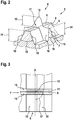
- a contrast structure 5 with hatching ribs 6, 7 each having a ridge 8, 9 and mutually opposite flanks 10 is formed on the contrast structure surface 4.
- the contrast structure 5 has intersection areas 11, with an intersection area 11 being precisely the area in which a second hatching rib 7 of the hatching ribs 6, 7 a first hatching rib 6 of the hatching ribs 6, 7 is arranged so that the ridge 9 of the second hatching rib 7 and the ridge 8 of the first hatching rib 6 cross in the top view and wherein a contour of the second hatching rib 7 has a local maximum 12 within the intersection area 11.
- FIG. 11 shows a top view of the FIG Fig. 2 shown section.
- the intersection area 11 is shown hatched.
- the second hatching rib 7 can largely follow a contour of the first hatching rib 6.
- the local maximum 12 can cut the ridge 8 of the first hatching rib 6 by an overlap height 13 of 0.05 mm to 0.4 mm, preferably 0.1 mm to 0.4 mm, particularly preferably 0.2 mm to 0.3 mm, overlay.
- the first hatching rib 6 and / or the second hatching rib 7 can have a height 14 from 0.1 mm to 1.0 mm, preferably from 0.2 mm to 0.8 mm, particularly preferably from 0.25 mm to 0.5 mm. As shown, the heights 14 of the two hatching ribs 6, 7 crossing in the intersection area 11 can differ from one another. In the figures, the height H is measured relative to the hatching base.
- the first hatching rib 6 can have mutually opposite flanks 10 which enclose a flank angle 15 of at least 50 °, preferably from 55 ° to 65 °, with one another.
- the second hatching rib 7 can have mutually opposite flanks 10 which enclose a flank angle 16 of 2 ° to 10 °, preferably 6 ° to 8 °, with one another.
- the first hatching rib 6 and the second hatching rib 7 can both enclose a flank angle 15, 16 of 2 ° to 10 °, preferably 6 ° to 8 °, with one another.
- the contrast structure 5 has several intersection areas 11. Preferably, several, particularly preferably all, intersection areas 11 are designed largely the same. The intersection areas can, however, differ from one another, in particular in terms of their overlap height 13.
- the contrast structure 5 accordingly has a plurality of first hatching ribs 6 and / or second hatching ribs 7.
- First hatching ribs 6 or second hatching ribs 7 can each be aligned largely parallel to one another.
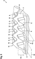
- FIGS. 4 to 6 show examples of arrangements of intersection areas 11 of a contrast structure 5 of a vehicle tire 1 according to the invention.
- the contrast structures 5 are outstandingly suitable for the in FIG Fig. 1 illustrated vehicle pneumatic tires 1.
- the individual intersection areas 11 can as with respect to Figures 2 and 3 be designed as described.
- the Fig. 4 shows a contrast structure 5 in which a large number of first hatching ribs 6 arranged largely parallel to one another each have a large number of intersection regions 11. Shown are two first hatching ribs 6 each with two intersection areas 11. The second hatching ribs 7 are each arranged parallel to one another. Every second hatching rib 7 of the intersection areas 11 crosses exactly one first hatching rib 6.
- the first hatching ribs 6 and / or the second hatching ribs 7 are each with a distance 18 of 0.2 mm to 1.0 mm, preferably with a distance of 0, 2 mm to 0.5 mm, particularly preferably at a distance of 0.25 mm to 0.35 mm, arranged from one another.
- the second hatching ribs 7 have a greater height 14 than the first hatching ribs 6.
- the Fig. 5 shows a section of a contrast structure 5 in which a second hatching rib 7 crosses a plurality of first hatching ribs 7 in intersection areas 11.
- the first hatching ribs 7 exactly cross the shown second hatching rib 7.
- the contrast structure 5 preferably has a large number of such structures, the second hatching ribs 7 preferably being arranged parallel to one another.
- the first hatching ribs 6 and / or the second hatching ribs 7 are each with a distance 18 of 0.2 mm to 1.0 mm, preferably with a distance of 0.2 mm to 0.5 mm, particularly preferably with a distance of 0 , 25 mm to 0.35 mm, arranged to one another.
- a direction of longitudinal extent of the first hatching ribs 6 with a direction of longitudinal extent of the second hatching ribs 7 can enclose an angle 17 of 30 ° to 90 °, preferably 45 ° to 90 °, particularly preferably 60 ° to 90 °, with one another.
- At least one further elevation 19, 19 ' preferably a fibrous further elevation 19 and / or a further elevation 19' connected to one of the first hatching ribs 6 or to one of the second hatching ribs 7, can be arranged within one of the parallelogram-shaped surfaces can.
- Several or all of the parallelogram-shaped surfaces can be formed with such a further elevation 19, 19 '.
- none of the areas can have a further elevation.
- the height 14 of the second hatching ribs 7 can be the minimum height between two intersection areas.
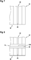
- the Figures 7 and 8 show a plan view of a molding tool 40 for producing the in FIGS Figures 2 and 3 illustrated intersection area 11.
- the Fig. 7 shows the molding tool 40 between steps b and c.
- the Fig. 8 shows the same molding tool after step c.
- the material removal in step c also takes place in the area of the first hatched groove 60 previously generated by material removal in step b, in particular in the area of the groove base 80. This results in a local minimum 120 in the intersection area, which is designed as a complementary negative structure to the local maximum 12 is.
- a linear engraving section 90 along which the laser beam was guided to generate the second hatched groove 70 in step c.
- the laser beam was preferably guided at constant speed and / or constant intensity along the respective at least one linear engraving section 90.
Landscapes
- Engineering & Computer Science (AREA)
- Mechanical Engineering (AREA)
- Moulds For Moulding Plastics Or The Like (AREA)
- Tires In General (AREA)
Applications Claiming Priority (1)
| Application Number | Priority Date | Filing Date | Title |
|---|---|---|---|
| DE102019215727.0A DE102019215727A1 (de) | 2019-10-14 | 2019-10-14 | Fahrzeugreifen aufweisend eine Kontraststrukturfläche und Verfahren zur Herstellung eines Formwerkzeugs |
Publications (2)
| Publication Number | Publication Date |
|---|---|
| EP3808549A1 true EP3808549A1 (fr) | 2021-04-21 |
| EP3808549B1 EP3808549B1 (fr) | 2022-11-09 |
Family
ID=72560439
Family Applications (1)
| Application Number | Title | Priority Date | Filing Date |
|---|---|---|---|
| EP20196638.9A Active EP3808549B1 (fr) | 2019-10-14 | 2020-09-17 | Pneus de véhicule comprenant une surface structurée contrastée et procédé de fabrication d'un outil de moulage |
Country Status (2)
| Country | Link |
|---|---|
| EP (1) | EP3808549B1 (fr) |
| DE (1) | DE102019215727A1 (fr) |
Cited By (1)
| Publication number | Priority date | Publication date | Assignee | Title |
|---|---|---|---|---|
| WO2023104259A1 (fr) * | 2021-12-06 | 2023-06-15 | Continental Reifen Deutschland Gmbh | Pneu de véhicule |
Citations (4)
| Publication number | Priority date | Publication date | Assignee | Title |
|---|---|---|---|---|
| EP1260387A2 (fr) * | 2001-05-25 | 2002-11-27 | The Goodyear Tire & Rubber Company | Flanc de pneumatique |
| EP2090444A1 (fr) * | 2006-12-04 | 2009-08-19 | Bridgestone Corporation | Pneu |
| JP2011037387A (ja) * | 2009-08-12 | 2011-02-24 | Yokohama Rubber Co Ltd:The | 空気入りタイヤ |
| US20120227879A1 (en) | 2009-09-28 | 2012-09-13 | Michelin Recherche Et Technique S.A. | High-contrast tire pattern and method for producing same |
-
2019
- 2019-10-14 DE DE102019215727.0A patent/DE102019215727A1/de not_active Withdrawn
-
2020
- 2020-09-17 EP EP20196638.9A patent/EP3808549B1/fr active Active
Patent Citations (4)
| Publication number | Priority date | Publication date | Assignee | Title |
|---|---|---|---|---|
| EP1260387A2 (fr) * | 2001-05-25 | 2002-11-27 | The Goodyear Tire & Rubber Company | Flanc de pneumatique |
| EP2090444A1 (fr) * | 2006-12-04 | 2009-08-19 | Bridgestone Corporation | Pneu |
| JP2011037387A (ja) * | 2009-08-12 | 2011-02-24 | Yokohama Rubber Co Ltd:The | 空気入りタイヤ |
| US20120227879A1 (en) | 2009-09-28 | 2012-09-13 | Michelin Recherche Et Technique S.A. | High-contrast tire pattern and method for producing same |
Cited By (2)
| Publication number | Priority date | Publication date | Assignee | Title |
|---|---|---|---|---|
| WO2023104259A1 (fr) * | 2021-12-06 | 2023-06-15 | Continental Reifen Deutschland Gmbh | Pneu de véhicule |
| US12485708B2 (en) | 2021-12-06 | 2025-12-02 | Continental Reifen Deutschland Gmbh | Pneumatic vehicle tire |
Also Published As
| Publication number | Publication date |
|---|---|
| EP3808549B1 (fr) | 2022-11-09 |
| DE102019215727A1 (de) | 2021-04-15 |
Similar Documents
| Publication | Publication Date | Title |
|---|---|---|
| DE69933260T2 (de) | Verfahren zum Gestalten eines Laufflächenprofils für Fahrzeugreifen | |
| AT394337B (de) | Radialreifen fuer lastkraftwagen | |
| DE10032372B4 (de) | Fahrzeugreifen | |
| EP3976396B1 (fr) | Pneumatique de véhicule présentant une surface hachurée | |
| DE102019217511A1 (de) | Fahrzeugluftreifen aufweisend eine Kontraststruktur | |
| EP2809528B1 (fr) | Pneu de véhicule | |
| EP3808549B1 (fr) | Pneus de véhicule comprenant une surface structurée contrastée et procédé de fabrication d'un outil de moulage | |
| DE60017184T2 (de) | Reifenlaufflächenprofil für fahrzeuge mit hoher belastungsfähigkeit | |
| EP4178813B1 (fr) | Pneus de véhicule ayant une structure de surface de contraste | |
| EP3808576B1 (fr) | Pneus de véhicule comportant une surface hachurée et un procédé de fabrication d'un outil de moulage | |
| DE10049936B4 (de) | Fahrzeugreifen | |
| DE102019214958A1 (de) | Fahrzeugreifen aufweisend eine Kontraststrukturfläche | |
| EP2372236A1 (fr) | Elément optique destiné à l'agencement dans un phare de véhicule | |
| AT400554B (de) | Fahrzeugreifen | |
| EP3976395B1 (fr) | Pneumatique de véhicule présentant une surface de marquage | |
| EP3792082B1 (fr) | Pneus de véhicule comprenant une zone de marquage | |
| EP4255740B1 (fr) | Pneumatique de véhicule comprenant une surface hachurée, moule de vulcanisation et procédé de production | |
| EP4028253B1 (fr) | Procédé de production combinée pour un outil de moulage pour la vulcanisation par moulage d'un pneumatique de véhicule et pneumatique de véhicule | |
| EP3838629B1 (fr) | Pneumatiques de véhicule comportant une structure de surface à contraste pourvue de nervures | |
| DE19844437A1 (de) | Fahrzeugreifen | |
| DE102022202534A1 (de) | Fahrzeugreifen mit Fahrzeugreifenkennzeichnung | |
| DE102018211146A1 (de) | Lamelle zur Verwendung in einer Vulkanisationsform zur Herstellung eines Fahrzeugreifens, eine entsprechende Vulkanisationsform, sowie ein Fahrzeugluftreifen und Verfahren zur Herstellung des Fahrzeugluftreifens |
Legal Events
| Date | Code | Title | Description |
|---|---|---|---|
| PUAI | Public reference made under article 153(3) epc to a published international application that has entered the european phase |
Free format text: ORIGINAL CODE: 0009012 |
|
| STAA | Information on the status of an ep patent application or granted ep patent |
Free format text: STATUS: THE APPLICATION HAS BEEN PUBLISHED |
|
| AK | Designated contracting states |
Kind code of ref document: A1 Designated state(s): AL AT BE BG CH CY CZ DE DK EE ES FI FR GB GR HR HU IE IS IT LI LT LU LV MC MK MT NL NO PL PT RO RS SE SI SK SM TR |
|
| AX | Request for extension of the european patent |
Extension state: BA ME |
|
| STAA | Information on the status of an ep patent application or granted ep patent |
Free format text: STATUS: REQUEST FOR EXAMINATION WAS MADE |
|
| 17P | Request for examination filed |
Effective date: 20211021 |
|
| RBV | Designated contracting states (corrected) |
Designated state(s): AL AT BE BG CH CY CZ DE DK EE ES FI FR GB GR HR HU IE IS IT LI LT LU LV MC MK MT NL NO PL PT RO RS SE SI SK SM TR |
|
| GRAP | Despatch of communication of intention to grant a patent |
Free format text: ORIGINAL CODE: EPIDOSNIGR1 |
|
| STAA | Information on the status of an ep patent application or granted ep patent |
Free format text: STATUS: GRANT OF PATENT IS INTENDED |
|
| INTG | Intention to grant announced |
Effective date: 20220426 |
|
| GRAJ | Information related to disapproval of communication of intention to grant by the applicant or resumption of examination proceedings by the epo deleted |
Free format text: ORIGINAL CODE: EPIDOSDIGR1 |
|
| STAA | Information on the status of an ep patent application or granted ep patent |
Free format text: STATUS: REQUEST FOR EXAMINATION WAS MADE |
|
| INTC | Intention to grant announced (deleted) | ||
| GRAP | Despatch of communication of intention to grant a patent |
Free format text: ORIGINAL CODE: EPIDOSNIGR1 |
|
| STAA | Information on the status of an ep patent application or granted ep patent |
Free format text: STATUS: GRANT OF PATENT IS INTENDED |
|
| INTG | Intention to grant announced |
Effective date: 20220809 |
|
| GRAS | Grant fee paid |
Free format text: ORIGINAL CODE: EPIDOSNIGR3 |
|
| GRAA | (expected) grant |
Free format text: ORIGINAL CODE: 0009210 |
|
| STAA | Information on the status of an ep patent application or granted ep patent |
Free format text: STATUS: THE PATENT HAS BEEN GRANTED |
|
| AK | Designated contracting states |
Kind code of ref document: B1 Designated state(s): AL AT BE BG CH CY CZ DE DK EE ES FI FR GB GR HR HU IE IS IT LI LT LU LV MC MK MT NL NO PL PT RO RS SE SI SK SM TR |
|
| REG | Reference to a national code |
Ref country code: GB Ref legal event code: FG4D Free format text: NOT ENGLISH |
|
| REG | Reference to a national code |
Ref country code: CH Ref legal event code: EP Ref country code: AT Ref legal event code: REF Ref document number: 1530084 Country of ref document: AT Kind code of ref document: T Effective date: 20221115 |
|
| REG | Reference to a national code |
Ref country code: DE Ref legal event code: R096 Ref document number: 502020001956 Country of ref document: DE |
|
| REG | Reference to a national code |
Ref country code: IE Ref legal event code: FG4D Free format text: LANGUAGE OF EP DOCUMENT: GERMAN |
|
| REG | Reference to a national code |
Ref country code: NL Ref legal event code: FP |
|
| REG | Reference to a national code |
Ref country code: LT Ref legal event code: MG9D |
|
| PG25 | Lapsed in a contracting state [announced via postgrant information from national office to epo] |
Ref country code: SE Free format text: LAPSE BECAUSE OF FAILURE TO SUBMIT A TRANSLATION OF THE DESCRIPTION OR TO PAY THE FEE WITHIN THE PRESCRIBED TIME-LIMIT Effective date: 20221109 Ref country code: PT Free format text: LAPSE BECAUSE OF FAILURE TO SUBMIT A TRANSLATION OF THE DESCRIPTION OR TO PAY THE FEE WITHIN THE PRESCRIBED TIME-LIMIT Effective date: 20230309 Ref country code: NO Free format text: LAPSE BECAUSE OF FAILURE TO SUBMIT A TRANSLATION OF THE DESCRIPTION OR TO PAY THE FEE WITHIN THE PRESCRIBED TIME-LIMIT Effective date: 20230209 Ref country code: LT Free format text: LAPSE BECAUSE OF FAILURE TO SUBMIT A TRANSLATION OF THE DESCRIPTION OR TO PAY THE FEE WITHIN THE PRESCRIBED TIME-LIMIT Effective date: 20221109 Ref country code: FI Free format text: LAPSE BECAUSE OF FAILURE TO SUBMIT A TRANSLATION OF THE DESCRIPTION OR TO PAY THE FEE WITHIN THE PRESCRIBED TIME-LIMIT Effective date: 20221109 Ref country code: ES Free format text: LAPSE BECAUSE OF FAILURE TO SUBMIT A TRANSLATION OF THE DESCRIPTION OR TO PAY THE FEE WITHIN THE PRESCRIBED TIME-LIMIT Effective date: 20221109 |
|
| PG25 | Lapsed in a contracting state [announced via postgrant information from national office to epo] |
Ref country code: RS Free format text: LAPSE BECAUSE OF FAILURE TO SUBMIT A TRANSLATION OF THE DESCRIPTION OR TO PAY THE FEE WITHIN THE PRESCRIBED TIME-LIMIT Effective date: 20221109 Ref country code: PL Free format text: LAPSE BECAUSE OF FAILURE TO SUBMIT A TRANSLATION OF THE DESCRIPTION OR TO PAY THE FEE WITHIN THE PRESCRIBED TIME-LIMIT Effective date: 20221109 Ref country code: LV Free format text: LAPSE BECAUSE OF FAILURE TO SUBMIT A TRANSLATION OF THE DESCRIPTION OR TO PAY THE FEE WITHIN THE PRESCRIBED TIME-LIMIT Effective date: 20221109 Ref country code: IS Free format text: LAPSE BECAUSE OF FAILURE TO SUBMIT A TRANSLATION OF THE DESCRIPTION OR TO PAY THE FEE WITHIN THE PRESCRIBED TIME-LIMIT Effective date: 20230309 Ref country code: HR Free format text: LAPSE BECAUSE OF FAILURE TO SUBMIT A TRANSLATION OF THE DESCRIPTION OR TO PAY THE FEE WITHIN THE PRESCRIBED TIME-LIMIT Effective date: 20221109 Ref country code: GR Free format text: LAPSE BECAUSE OF FAILURE TO SUBMIT A TRANSLATION OF THE DESCRIPTION OR TO PAY THE FEE WITHIN THE PRESCRIBED TIME-LIMIT Effective date: 20230210 |
|
| P01 | Opt-out of the competence of the unified patent court (upc) registered |
Effective date: 20230602 |
|
| PG25 | Lapsed in a contracting state [announced via postgrant information from national office to epo] |
Ref country code: SM Free format text: LAPSE BECAUSE OF FAILURE TO SUBMIT A TRANSLATION OF THE DESCRIPTION OR TO PAY THE FEE WITHIN THE PRESCRIBED TIME-LIMIT Effective date: 20221109 Ref country code: RO Free format text: LAPSE BECAUSE OF FAILURE TO SUBMIT A TRANSLATION OF THE DESCRIPTION OR TO PAY THE FEE WITHIN THE PRESCRIBED TIME-LIMIT Effective date: 20221109 Ref country code: EE Free format text: LAPSE BECAUSE OF FAILURE TO SUBMIT A TRANSLATION OF THE DESCRIPTION OR TO PAY THE FEE WITHIN THE PRESCRIBED TIME-LIMIT Effective date: 20221109 Ref country code: DK Free format text: LAPSE BECAUSE OF FAILURE TO SUBMIT A TRANSLATION OF THE DESCRIPTION OR TO PAY THE FEE WITHIN THE PRESCRIBED TIME-LIMIT Effective date: 20221109 Ref country code: CZ Free format text: LAPSE BECAUSE OF FAILURE TO SUBMIT A TRANSLATION OF THE DESCRIPTION OR TO PAY THE FEE WITHIN THE PRESCRIBED TIME-LIMIT Effective date: 20221109 |
|
| REG | Reference to a national code |
Ref country code: DE Ref legal event code: R097 Ref document number: 502020001956 Country of ref document: DE |
|
| PG25 | Lapsed in a contracting state [announced via postgrant information from national office to epo] |
Ref country code: SK Free format text: LAPSE BECAUSE OF FAILURE TO SUBMIT A TRANSLATION OF THE DESCRIPTION OR TO PAY THE FEE WITHIN THE PRESCRIBED TIME-LIMIT Effective date: 20221109 Ref country code: AL Free format text: LAPSE BECAUSE OF FAILURE TO SUBMIT A TRANSLATION OF THE DESCRIPTION OR TO PAY THE FEE WITHIN THE PRESCRIBED TIME-LIMIT Effective date: 20221109 |
|
| PLBE | No opposition filed within time limit |
Free format text: ORIGINAL CODE: 0009261 |
|
| STAA | Information on the status of an ep patent application or granted ep patent |
Free format text: STATUS: NO OPPOSITION FILED WITHIN TIME LIMIT |
|
| 26N | No opposition filed |
Effective date: 20230810 |
|
| PG25 | Lapsed in a contracting state [announced via postgrant information from national office to epo] |
Ref country code: SI Free format text: LAPSE BECAUSE OF FAILURE TO SUBMIT A TRANSLATION OF THE DESCRIPTION OR TO PAY THE FEE WITHIN THE PRESCRIBED TIME-LIMIT Effective date: 20221109 |
|
| REG | Reference to a national code |
Ref country code: DE Ref legal event code: R081 Ref document number: 502020001956 Country of ref document: DE Owner name: CONTINENTAL REIFEN DEUTSCHLAND GMBH, DE Free format text: FORMER OWNER: CONTINENTAL REIFEN DEUTSCHLAND GMBH, 30165 HANNOVER, DE |
|
| REG | Reference to a national code |
Ref country code: CH Ref legal event code: PL |
|
| PG25 | Lapsed in a contracting state [announced via postgrant information from national office to epo] |
Ref country code: LU Free format text: LAPSE BECAUSE OF NON-PAYMENT OF DUE FEES Effective date: 20230917 |
|
| REG | Reference to a national code |
Ref country code: BE Ref legal event code: MM Effective date: 20230930 |
|
| PG25 | Lapsed in a contracting state [announced via postgrant information from national office to epo] |
Ref country code: LU Free format text: LAPSE BECAUSE OF NON-PAYMENT OF DUE FEES Effective date: 20230917 Ref country code: IT Free format text: LAPSE BECAUSE OF FAILURE TO SUBMIT A TRANSLATION OF THE DESCRIPTION OR TO PAY THE FEE WITHIN THE PRESCRIBED TIME-LIMIT Effective date: 20221109 Ref country code: MC Free format text: LAPSE BECAUSE OF FAILURE TO SUBMIT A TRANSLATION OF THE DESCRIPTION OR TO PAY THE FEE WITHIN THE PRESCRIBED TIME-LIMIT Effective date: 20221109 |
|
| REG | Reference to a national code |
Ref country code: IE Ref legal event code: MM4A |
|
| PG25 | Lapsed in a contracting state [announced via postgrant information from national office to epo] |
Ref country code: IE Free format text: LAPSE BECAUSE OF NON-PAYMENT OF DUE FEES Effective date: 20230917 |
|
| PG25 | Lapsed in a contracting state [announced via postgrant information from national office to epo] |
Ref country code: CH Free format text: LAPSE BECAUSE OF NON-PAYMENT OF DUE FEES Effective date: 20230930 |
|
| PG25 | Lapsed in a contracting state [announced via postgrant information from national office to epo] |
Ref country code: IE Free format text: LAPSE BECAUSE OF NON-PAYMENT OF DUE FEES Effective date: 20230917 Ref country code: CH Free format text: LAPSE BECAUSE OF NON-PAYMENT OF DUE FEES Effective date: 20230930 |
|
| PG25 | Lapsed in a contracting state [announced via postgrant information from national office to epo] |
Ref country code: BE Free format text: LAPSE BECAUSE OF NON-PAYMENT OF DUE FEES Effective date: 20230930 |
|
| PG25 | Lapsed in a contracting state [announced via postgrant information from national office to epo] |
Ref country code: BG Free format text: LAPSE BECAUSE OF FAILURE TO SUBMIT A TRANSLATION OF THE DESCRIPTION OR TO PAY THE FEE WITHIN THE PRESCRIBED TIME-LIMIT Effective date: 20221109 |
|
| PG25 | Lapsed in a contracting state [announced via postgrant information from national office to epo] |
Ref country code: BG Free format text: LAPSE BECAUSE OF FAILURE TO SUBMIT A TRANSLATION OF THE DESCRIPTION OR TO PAY THE FEE WITHIN THE PRESCRIBED TIME-LIMIT Effective date: 20221109 |
|
| GBPC | Gb: european patent ceased through non-payment of renewal fee |
Effective date: 20240917 |
|
| PG25 | Lapsed in a contracting state [announced via postgrant information from national office to epo] |
Ref country code: GB Free format text: LAPSE BECAUSE OF NON-PAYMENT OF DUE FEES Effective date: 20240917 |
|
| PG25 | Lapsed in a contracting state [announced via postgrant information from national office to epo] |
Ref country code: CY Free format text: LAPSE BECAUSE OF FAILURE TO SUBMIT A TRANSLATION OF THE DESCRIPTION OR TO PAY THE FEE WITHIN THE PRESCRIBED TIME-LIMIT; INVALID AB INITIO Effective date: 20200917 |
|
| PG25 | Lapsed in a contracting state [announced via postgrant information from national office to epo] |
Ref country code: HU Free format text: LAPSE BECAUSE OF FAILURE TO SUBMIT A TRANSLATION OF THE DESCRIPTION OR TO PAY THE FEE WITHIN THE PRESCRIBED TIME-LIMIT; INVALID AB INITIO Effective date: 20200917 |
|
| PGFP | Annual fee paid to national office [announced via postgrant information from national office to epo] |
Ref country code: DE Payment date: 20250930 Year of fee payment: 6 |
|
| PGFP | Annual fee paid to national office [announced via postgrant information from national office to epo] |
Ref country code: NL Payment date: 20250918 Year of fee payment: 6 |
|
| PGFP | Annual fee paid to national office [announced via postgrant information from national office to epo] |
Ref country code: AT Payment date: 20251020 Year of fee payment: 5 Ref country code: FR Payment date: 20250922 Year of fee payment: 6 |
|
| PG25 | Lapsed in a contracting state [announced via postgrant information from national office to epo] |
Ref country code: TR Free format text: LAPSE BECAUSE OF FAILURE TO SUBMIT A TRANSLATION OF THE DESCRIPTION OR TO PAY THE FEE WITHIN THE PRESCRIBED TIME-LIMIT Effective date: 20221109 |