EP3810903B1 - Fussplatte eines turbinenmotors - Google Patents
Fussplatte eines turbinenmotors Download PDFInfo
- Publication number
- EP3810903B1 EP3810903B1 EP19731293.7A EP19731293A EP3810903B1 EP 3810903 B1 EP3810903 B1 EP 3810903B1 EP 19731293 A EP19731293 A EP 19731293A EP 3810903 B1 EP3810903 B1 EP 3810903B1
- Authority
- EP
- European Patent Office
- Prior art keywords
- assembly
- orifices
- section
- flanges
- sections
- Prior art date
- Legal status (The legal status is an assumption and is not a legal conclusion. Google has not performed a legal analysis and makes no representation as to the accuracy of the status listed.)
- Active
Links
Images
Classifications
-
- F—MECHANICAL ENGINEERING; LIGHTING; HEATING; WEAPONS; BLASTING
- F01—MACHINES OR ENGINES IN GENERAL; ENGINE PLANTS IN GENERAL; STEAM ENGINES
- F01D—NON-POSITIVE DISPLACEMENT MACHINES OR ENGINES, e.g. STEAM TURBINES
- F01D17/00—Regulating or controlling by varying flow
- F01D17/10—Final actuators
- F01D17/12—Final actuators arranged in stator parts
- F01D17/14—Final actuators arranged in stator parts varying effective cross-sectional area of nozzles or guide conduits
- F01D17/16—Final actuators arranged in stator parts varying effective cross-sectional area of nozzles or guide conduits by means of nozzle vanes
- F01D17/162—Final actuators arranged in stator parts varying effective cross-sectional area of nozzles or guide conduits by means of nozzle vanes for axial flow, i.e. the vanes turning around axes which are essentially perpendicular to the rotor centre line
-
- F—MECHANICAL ENGINEERING; LIGHTING; HEATING; WEAPONS; BLASTING
- F04—POSITIVE - DISPLACEMENT MACHINES FOR LIQUIDS; PUMPS FOR LIQUIDS OR ELASTIC FLUIDS
- F04D—NON-POSITIVE-DISPLACEMENT PUMPS
- F04D29/00—Details, component parts, or accessories
- F04D29/40—Casings; Connections of working fluid
- F04D29/52—Casings; Connections of working fluid for axial pumps
- F04D29/54—Fluid-guiding means, e.g. diffusers
- F04D29/56—Fluid-guiding means, e.g. diffusers adjustable
- F04D29/563—Fluid-guiding means, e.g. diffusers adjustable specially adapted for elastic fluid pumps
-
- F—MECHANICAL ENGINEERING; LIGHTING; HEATING; WEAPONS; BLASTING
- F04—POSITIVE - DISPLACEMENT MACHINES FOR LIQUIDS; PUMPS FOR LIQUIDS OR ELASTIC FLUIDS
- F04D—NON-POSITIVE-DISPLACEMENT PUMPS
- F04D29/00—Details, component parts, or accessories
- F04D29/60—Mounting; Assembling; Disassembling
- F04D29/64—Mounting; Assembling; Disassembling of axial pumps
- F04D29/644—Mounting; Assembling; Disassembling of axial pumps especially adapted for elastic fluid pumps
-
- F—MECHANICAL ENGINEERING; LIGHTING; HEATING; WEAPONS; BLASTING
- F05—INDEXING SCHEMES RELATING TO ENGINES OR PUMPS IN VARIOUS SUBCLASSES OF CLASSES F01-F04
- F05D—INDEXING SCHEME FOR ASPECTS RELATING TO NON-POSITIVE-DISPLACEMENT MACHINES OR ENGINES, GAS-TURBINES OR JET-PROPULSION PLANTS
- F05D2220/00—Application
- F05D2220/30—Application in turbines
- F05D2220/32—Application in turbines in gas turbines
-
- F—MECHANICAL ENGINEERING; LIGHTING; HEATING; WEAPONS; BLASTING
- F05—INDEXING SCHEMES RELATING TO ENGINES OR PUMPS IN VARIOUS SUBCLASSES OF CLASSES F01-F04
- F05D—INDEXING SCHEME FOR ASPECTS RELATING TO NON-POSITIVE-DISPLACEMENT MACHINES OR ENGINES, GAS-TURBINES OR JET-PROPULSION PLANTS
- F05D2220/00—Application
- F05D2220/30—Application in turbines
- F05D2220/32—Application in turbines in gas turbines
- F05D2220/323—Application in turbines in gas turbines for aircraft propulsion, e.g. jet engines
-
- F—MECHANICAL ENGINEERING; LIGHTING; HEATING; WEAPONS; BLASTING
- F05—INDEXING SCHEMES RELATING TO ENGINES OR PUMPS IN VARIOUS SUBCLASSES OF CLASSES F01-F04
- F05D—INDEXING SCHEME FOR ASPECTS RELATING TO NON-POSITIVE-DISPLACEMENT MACHINES OR ENGINES, GAS-TURBINES OR JET-PROPULSION PLANTS
- F05D2230/00—Manufacture
- F05D2230/60—Assembly methods
-
- F—MECHANICAL ENGINEERING; LIGHTING; HEATING; WEAPONS; BLASTING
- F05—INDEXING SCHEMES RELATING TO ENGINES OR PUMPS IN VARIOUS SUBCLASSES OF CLASSES F01-F04
- F05D—INDEXING SCHEME FOR ASPECTS RELATING TO NON-POSITIVE-DISPLACEMENT MACHINES OR ENGINES, GAS-TURBINES OR JET-PROPULSION PLANTS
- F05D2240/00—Components
- F05D2240/10—Stators
- F05D2240/12—Fluid guiding means, e.g. vanes
- F05D2240/128—Nozzles
-
- Y—GENERAL TAGGING OF NEW TECHNOLOGICAL DEVELOPMENTS; GENERAL TAGGING OF CROSS-SECTIONAL TECHNOLOGIES SPANNING OVER SEVERAL SECTIONS OF THE IPC; TECHNICAL SUBJECTS COVERED BY FORMER USPC CROSS-REFERENCE ART COLLECTIONS [XRACs] AND DIGESTS
- Y02—TECHNOLOGIES OR APPLICATIONS FOR MITIGATION OR ADAPTATION AGAINST CLIMATE CHANGE
- Y02T—CLIMATE CHANGE MITIGATION TECHNOLOGIES RELATED TO TRANSPORTATION
- Y02T50/00—Aeronautics or air transport
- Y02T50/60—Efficient propulsion technologies, e.g. for aircraft
Definitions
- the invention relates to the field of axial turbomachines and more particularly aircraft turbojets. More specifically, the invention relates to an assembly for an axial turbomachine, in particular for an aircraft turbojet, the assembly comprising an annular row of steerable stator blades, a device for actuating the pivoting of the blades and an external shroud having a cylindrical surface forming a seat for the actuating device.
- the invention also relates to a turbomachine equipped with such an assembly.
- the document US 2016/0160675 describes an axial turbomachine with a particular arrangement of the journals of variable-orientation stator blades in an external compressor shell.
- the blade orientation actuation system is positioned downstream of each blade.
- a connecting rod, denoted 80, is used to adjust the pivoting of the blades.
- This connecting rod can be manipulated by a synchronizing ring, so that all the blades of a given stage are oriented identically.
- the synchronizing ring is also called a maneuvering ring, actuation ring or control ring. Such a ring can sometimes rest directly on the external shell.
- EP 0 636 766 A1 , US 4 130 375 A , GB 805 015 A , US 3,314,654 A And WO 2014/143445 A2 disclose other examples of steerable stator blade devices.
- the invention aims to solve at least one of the problems posed by the prior art.
- the invention also aims to propose a simpler and more compact design, allowing easier assembly of the blades at variable orientation and the orientation actuation mechanism.
- the invention also aims to provide a lightweight solution.
- the invention relates to an assembly according to claim 1.
- ferrule is meant a part substantially of revolution around an axis.
- the axial sections of a ferrule are portions of a ferrule.
- the cylindrical surface surrounds the flanges and makes the whole more compact.
- the invention also relates to an axial turbomachine, in particular an aircraft turbojet, with a low-pressure compressor, a high-pressure compressor and an intermediate vein between the low-pressure compressor and the high-pressure compressor, remarkable in that the low-pressure compressor, the intermediate vein and/or the high-pressure compressor comprises/comprise an assembly as described above.
- a method of assembling such an assembly using such a kit comprising the following steps: introducing the heads of the blades into the radial orifices of the first section; assembling the pads, rods and connecting rods to the ring; assembling a control connecting rod to the head of each blade; fixing, preferably by screwing, the flanges of the two sections together.
- the method comprises a step of assembling the half-sections carried out after the step of assembling the connecting rods to the blades.
- the invention proposes a specific geometry which is particularly compact.
- the positioning of the cylindrical surface above the flanges allows good rigidity of the seat of the actuating device.
- the terms “internal” and “external” refer to a positioning relative to the axis of rotation of an axial turbomachine.
- the axial direction corresponds to the direction along the axis of rotation of the turbomachine.
- the radial direction is perpendicular to the axis of rotation.
- the upstream and downstream refer to the main flow direction of the flow in the turbomachine.
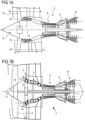
- FIG. 1A represents in a simplified manner an axial turbomachine.
- This is a dual-flow turbojet.
- the turbojet 2 comprises a first compression level, called low-pressure compressor 4, a second compression level, called high-pressure compressor 6, a combustion chamber 8 and one or more turbine levels 10.
- the mechanical power of the turbine 10 transmitted via the central shaft to the rotor 12 sets the two compressors 4 and 6 in motion.
- the latter comprise several rows of rotor blades associated with rows of stator blades.
- the rotation of the rotor about its axis of rotation 14 thus makes it possible to generate an air flow and to gradually compress the latter up to the inlet of the combustion chamber 8.
- An inlet fan commonly referred to as a fan or blower 16 is coupled to the rotor 12 via a gear train 17, and generates an air flow which is divided into a primary flow 18 passing through the various aforementioned levels of the turbomachine, and into a secondary flow 20 passing through an annular duct (partially shown) along the machine to then join the primary flow at the turbine outlet.
- the secondary flow can be accelerated so as to generate a thrust reaction necessary for the flight of an aircraft.
- the primary flow 18 and secondary flow 20 are coaxial annular flows fitted into each other.
- FIG. 1B represents an axial turbomachine 2 with an alternative architecture to that of the Figure 1A .
- the same reference numbers represent the same elements.
- the difference between the two architectures is the presence of a casing 11 carrying the reducer 17, in particular via radial arms (called “struts") 13.
- the radial arms 13 can be directly downstream of a row of stator blades 15.
- the illustrated embodiment is related to the architecture of the Figure 1A but all the technical characteristics of the invention can also be provided on a turbomachine with an architecture according to the Figure 1B .
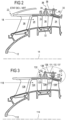
- FIG 2 is a sectional view of a compressor of an axial turbomachine such as that of the figure 1 , with an external shroud according to the state of the art.
- the compressor may be a low-pressure compressor 4.
- the rotor 12 comprises several rows of rotor blades 24. It may consist of a single-piece bladed drum or single-piece bladed discs. Alternatively, it may comprise blades with dovetail attachment.
- the low-pressure compressor 4 comprises several rectifiers, for example four, which each contain a row of stator blades 26. Some stator blades may have adjustable orientation, also called variable-pitch blades.
- the rectifiers are respectively associated with a row of rotor blades to straighten the air flow, so as to convert the speed of the flow into pressure, in particular into static pressure.
- a nozzle 22 which may have defrosting functions may be mounted on a housing which supports a row of inlet stator vanes 28.
- the stator vanes 26 extend substantially radially from an outer shroud 30 to inner rings 32.
- the vanes 26 may be secured to the outer shroud 30 by pins or journals 34.
- the shroud 30 defines an inner surface 29 that guides the gas flow.
- the compressor may have a plurality of adjacent axial sections to form the shroud 30.
- journal 34 is pivotally driven by a connecting rod 36 around the axis 38 of the journal 34.
- the connecting rod 36 is secured to the journal 34, fixed for example by a nut.
- the connecting rods of the annular row of blades 26 are all connected to a synchronizing ring 40 by means of rods 42.
- the ring 40 rests on a cylindrical or conical surface 37.
- FIG. 3 partially represents the compressor assembled from an assembly according to the invention.
- the numbers are incremented by 100 to designate technical characteristics corresponding to those of the figure 2 .
- the shell of the invention comprises a first section 130 and a second section 230.
- the sections describe an internal gas flow guiding surface 129, 229.
- the sections comprise respective flanges 131, 231 placed opposite each other to assemble the compressor.
- the first section 130 has a tubular wall 132 defining a cylindrical external surface 137.
- the blade 126 comprises a vane 142 having a leading edge 144 and a trailing edge 146.
- the head of the blade 126 may comprise a shoulder 148 for centering and positioning the blade 126 in the shroud 130 as well as a groove for receiving a seal.
- the connecting rod 136 for operating the pivoting of the blade is fixed by a nut 150 on a threaded portion 152 of the head of the blade.
- a centering chamfer 154 may be provided at the end of the journal 134.
- the head of the blade is received at the right of an excess thickness of the ferrule 130, which can be in the form of a boss 133.
- the connecting rod 136 may comprise a conical orifice 160 corresponding to the chamfer 154, a body 162 and a lug 164.
- the orifice 160 may comprise a groove for receiving a key and thus making the blade 126 and the connecting rod 136 rotationally integral.
- tubular wall 132 is integral with the flange 131. Together, these form a “T” profile. Alternatively, the tubular wall may be radially spaced from the flange.
- An axis 135 schematizes the junction between the flanges 131, 231 which can be made by screwed elements.
- the cylindrical surface 137 acts as a support for pads 166 carried by the ring 140.
- a rod 168 provides the connection between the connecting rod 136 and the ring 140.
- a sleeve 170 provides the connection of the pads 166 to the rod 168 and/or to the ring 140.
- the ring 140 is in the form of a full ring or two half-rings, with a plurality of radial orifices penetrated by the rods 168. These orifices can be threaded.
- the 140 ring may have annular grooves on its upstream and downstream face in order to optimize its weight without compromising its rigidity.
- the synchronizing ring 140 cooperates with as many rods 168 as there are connecting rods 136 distributed annularly.
- the ring 140 can be actuated in pivoting about the axis 114 by suitable means such as for example a toothed wheel cooperating with a rack provided on the ring 140.
- the rack can be housed in one of the grooves of the ring 140.
- the pivoting of the ring 140 causes a corresponding movement of the rods 168 along the surface 137 and these thus pivot the connecting rods 136 and the blades 126 about their axes 138.
- the pads 166 can be directly connected to the ring 140 or to the rod 168.
- an intermediate sleeve 170 may be provided for each rod 168 and each pad 166.
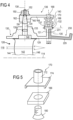
- the sleeve 170 is described on the figure 5 .
- This comprises a tubular portion 172 which can be threaded on the outside to be inserted into the ring 140 and/or on the inside to receive the rod 168.
- the sleeve also comprises a rectangular portion 174 which makes it possible to hold the pad 166 by gluing, shrinking or screwing - for example using a countersunk screw 180 inserted from below and the head of which will be embedded in the pad 166.
- the portion 174 can alternatively be cylindrical to accommodate a cylindrical pad.
- the external ferrule 130 has an orifice 139 receiving the journal 134.
- the journal 134 is inserted into the orifice 139 from below (in the direction of the figure 4 ), then the connecting rod 136 is screwed using thread 52.
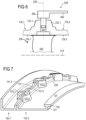
- the blade 226 is in one piece with the connecting rod 236 and the orifice of the ferrule 130 receiving the journal 234 is made of two half-orifices (139.1, 139.2 on the figure 7 ).
- Two half-sections 130.1 and 130.2 form the shroud 130.
- Each of the half-sections 130.1, 130.2 comprises a tubular wall defining an internal guide surface 129.1, 129.2 and an annular series of half-orifices 139.1, 139.2, formed in half-bosses 133.1, 133.2.
- the two half-orifices 139.1, 139.2 form the orifice 139 which receives the journal 234 of the blade 226.
- the two half-sections 130.1, 130.2 are assembled via screwed elements which hold two adjacent flanges 131.1, 131.2 together.
- the flanges 131.1, 131.2 may extend from one boss to the adjacent boss circumferentially.
- the connecting rod 236 is integral with the blade head.
- the connecting rod may be forged or cast with the rest of the blade.
- the functional surfaces (journal, extrados/intrados) are then machined.
- a welded assembly may be made. This is done before the blade is mounted in the shroud. Since the orifice 139 results from the combination of the two half-sections 130.1, 130.2, the journal 234 can be positioned in a half-orifice 139.1, 139.2 of the half-section 130.1 despite the dimension of the connecting rod which is greater than the diameter of the orifice 139, then the other half-section 130.2 is fixed to grip the journal 234 in the orifice 139.
- the synchronizing ring provided with its pads can be mounted on the second section of the shell before the blades are mounted in the half-orifices 139.1, 139.2.
- FIG. 7 represents a partial isometric view of the shell 130 of this second embodiment.
- the bosses 133.1, 133.2 as well as the flanges 131.1, 131.2 and their assembly holes can be seen (only the holes 235 of the downstream half-section 130.2 are visible).
- the flanges can completely connect each of the bosses 133.1, 133.2 to the neighboring boss.
- the upstream half-section 130.1 comprises a flange 131.3 which makes it possible to connect the shell to the compressor nozzle.
- the downstream half-section 130.2 comprises the bearing surface 137 on the tubular wall 132, which forms a “T” profile with the flange 131.
- the surface 137 is presented as cylindrical but in an unclaimed embodiment it is also possible to provide any profile for the surface 137, in particular conical or with a profile complementary to that of the pads such as in particular an external groove making it possible to guide pads provided with a pin extending radially inwards.
Landscapes
- Engineering & Computer Science (AREA)
- Mechanical Engineering (AREA)
- General Engineering & Computer Science (AREA)
- Structures Of Non-Positive Displacement Pumps (AREA)
Claims (12)
- Eine Baugruppe für eine Axialturbomaschine (2), insbesondere für Flugzeug-Turbotriebwerke, wobei die Baugruppe Folgendes umfasst:- eine ringförmige Anordnung von Statorschaufeln (126), die jeweils eine Schaufel (142) und einen radialen Kopf (134, 148, 154) aufweisen, der eine zylindrische Nabe (134) enthält; wobei die Schaufeln (126) um die Nabenachse (138) schwenkbar sind;- eine Betätigungsvorrichtung (136, 140, 166, 168, 170) zum Schwenken der Schaufeln (126), die einen Synchronisierungsring (140) und Betätigungsstangen (136) umfasst, die den Synchronisierungsring (140) mit jeder der Schaufeln (126) verbinden;- einen äußeren Ring (130, 230), der eine rohrförmige Wand umfasst und eine ringförmige Anordnung von Radialöffnungen (139) aufweist, in die die Enden (134, 148, 154) der Schaufeln (126) eingreifen,wobei der Ring (130, 230) zwei axial benachbarte rohrförmige Abschnitte (130, 230) umfasst, wobei die Abschnitte (130, 230) mittels entsprechender Flansche (131, 231) zusammengefügt sind, dadurch gekennzeichnet, dass der erste Abschnitt (130) eine zylindrische Fläche (137) aufweist, die koaxial zu dem Abschnitt (130) ist und eine Aussparung für das Betätigungselement (136, 140, 166, 168, 170) bildet, und dadurch, dass die zylindrische Fläche (137) eine Außenfläche einer rohrförmigen Wand (132) ist, die die beiden Flansche (131, 231) axial überlappt.
- Die Baugruppe nach Anspruch 1, dadurch gekennzeichnet, dass die rohrförmige Wand (132) und der Flansch (131) des ersten Abschnitts (130) ein "T"-Profil bilden.
- Die Baugruppe nach einem der Ansprüche 1 oder 2, dadurch gekennzeichnet, dass die rohrförmige Wand (132) und der Flansch (131) des ersten Abschnitts (130) aus einem Stück gefertigt sind.
- Die Baugruppe nach einem der Ansprüche 1 bis 3, dadurch gekennzeichnet, dass sie Schuhe (166) umfasst, die an dem Ring (140) befestigt sind und mit der zylindrischen Fläche (137) in Kontakt kommen.
- Die Baugruppe nach dem vorhergehenden Anspruch, dadurch gekennzeichnet, dass sie Hülsen (170) umfasst, die jeweils einen rohrförmigen Teil (172) für das Zusammenwirken mit einer Stange (168) oder einem Ring (140) und einen rechteckigen (174) oder zylindrischen Teil für das Zusammenwirken mit einem Schuh (166) aufweisen.
- Die Baugruppe nach einem der Ansprüche 1 bis 5, dadurch gekennzeichnet, dass sie eine Vielzahl von Schrauben-Bolzen-Paaren umfasst, wobei die Flansche (131, 231) Öffnungen aufweisen, durch die die Bolzen hindurchgehen können, um die Abschnitte (130, 230) durch Verschraubung zusammenzuhalten.
- Die Baugruppe nach dem vorhergehenden Anspruch, dadurch gekennzeichnet, dass die Löcher axial sind und die Muttern parallel zur zylindrischen Oberfläche (137) sind.
- Die Baugruppe nach einem der Ansprüche 1 bis 7, dadurch gekennzeichnet, dass mindestens einer der Flansche (131, 231) und/oder die rohrförmige Wand (132) und/oder die Abschnitte (130, 230) aus einer Titan-, Aluminium- oder Magnesiumlegierung und/oder einem Verbundwerkstoff hergestellt ist/sind.
- Die Baugruppe nach einem der Ansprüche 1 bis 8, dadurch gekennzeichnet, dass der erste Abschnitt (130) aus einer Baugruppe von zwei Halbabschnitten (130.1, 130.2) hergestellt ist, wobei jeder der Halbabschnitte (130.1, 130.2) eine ringförmige Anordnung von halbzylindrischen radialen Halböffnungen (139.1, 139.2) aufweist, wobei die Halböffnungen (139.1, 139.2) so angeordnet sind, dass jede der Halböffnungen (139.1, 139.2) eines Halbabschnitts (130.1, 130.2) in axiale und umfängliche Übereinstimmung mit einer Halböffnung (139.1, 139.2) des anderen Halbabschnitts (130.1, 130.2) gebracht werden kann, um die ringförmige Reihe von Radialöffnungen (139) zu bilden.
- Die Baugruppe nach dem vorhergehenden Anspruch, dadurch gekennzeichnet, dass die Halbabschnitte (130.1, 130.2) mittels jeweiliger Flansche (131.1, 131.2) zusammengefügt werden, die in Umfangsrichtung zwischen zwei benachbarten Halblöchern (139.1, 139.2) angeordnet sind, wobei jeder Umfangsabstand zwischen zwei benachbarten Halblöchern (139.1, 139.2) einen der Flansche (131.1, 131.2) enthält.
- Die Baugruppe nach einem der Ansprüche 1 bis 10, dadurch gekennzeichnet, dass die Flansche (131, 231) senkrecht zur Symmetrieachse (114) der Hülse verlaufende Flansche mit einer axialen Dicke (E1, E2) sind, wobei sich die zylindrische Fläche (137) axial über eine Länge (L) erstreckt, die größer ist als das Dreifache der Summe der axialen Dicken (E1, E2) der beiden Flansche (131, 231).
- Eine Axialturbomaschine (2), insbesondere Flugzeug-Turbotriebwerk, mit einem Niederdruckverdichter (4), einem Hochdruckverdichter (6) und einem Zwischenkanal zwischen dem Niederdruckverdichter (4) und dem Hochdruckverdichter (6), dadurch gekennzeichnet, dass der Niederdruckverdichter (4), der Zwischenkanal und/oder der Hochdruckverdichter (6) eine Baugruppe nach einem der Ansprüche 1 oder 11 umfassen.
Applications Claiming Priority (2)
| Application Number | Priority Date | Filing Date | Title |
|---|---|---|---|
| BE20185429A BE1026411B1 (fr) | 2018-06-21 | 2018-06-21 | Virole extérieure de turbomachine |
| PCT/EP2019/066318 WO2019243484A1 (fr) | 2018-06-21 | 2019-06-20 | Virole extérieure de turbomachine |
Publications (2)
| Publication Number | Publication Date |
|---|---|
| EP3810903A1 EP3810903A1 (de) | 2021-04-28 |
| EP3810903B1 true EP3810903B1 (de) | 2025-02-12 |
Family
ID=62985847
Family Applications (1)
| Application Number | Title | Priority Date | Filing Date |
|---|---|---|---|
| EP19731293.7A Active EP3810903B1 (de) | 2018-06-21 | 2019-06-20 | Fussplatte eines turbinenmotors |
Country Status (5)
| Country | Link |
|---|---|
| US (1) | US11236634B2 (de) |
| EP (1) | EP3810903B1 (de) |
| CN (1) | CN111051652B (de) |
| BE (1) | BE1026411B1 (de) |
| WO (1) | WO2019243484A1 (de) |
Families Citing this family (5)
| Publication number | Priority date | Publication date | Assignee | Title |
|---|---|---|---|---|
| BE1026199B1 (fr) * | 2018-04-10 | 2019-11-12 | Safran Aero Boosters S.A. | Virole exterieure en deux parties |
| BE1027280B1 (fr) | 2019-05-16 | 2020-12-15 | Safran Aero Boosters Sa | Carter de compresseur pour turbomachine |
| DE102021121462A1 (de) | 2021-08-18 | 2023-02-23 | MTU Aero Engines AG | Verstellbare Leitschaufel für eine Gasturbine, Gasturbine und Verfahren zur Montage einer verstellbaren Leitschaufel für eine Gasturbine |
| EP4534806A1 (de) | 2023-10-02 | 2025-04-09 | Safran Aero Boosters | Vorrichtung zur steuerung der schaufelausrichtung eines schaufelgitters mit veränderbarer ausrichtung einer flugzeugturbomaschine |
| BE1032726B1 (fr) * | 2024-06-28 | 2026-02-03 | Safran Aero Boosters | Ensemble redresseur pour compresseur basse pression de turbomachine |
Family Cites Families (20)
| Publication number | Priority date | Publication date | Assignee | Title |
|---|---|---|---|---|
| BE514728A (de) * | 1951-10-10 | |||
| NL86599C (de) * | 1955-06-17 | |||
| US3314654A (en) * | 1965-07-30 | 1967-04-18 | Gen Electric | Variable area turbine nozzle for axial flow gas turbine engines |
| CA1034509A (en) * | 1975-10-14 | 1978-07-11 | Westinghouse Canada Limited | Vane rotator assembly for a gas turbine |
| US4363600A (en) * | 1981-04-06 | 1982-12-14 | General Motors Corporation | Variable vane mounting |
| GB2210935B (en) * | 1987-10-10 | 1992-05-27 | Rolls Royce Plc | Variable stator vane assembly |
| US4834613A (en) * | 1988-02-26 | 1989-05-30 | United Technologies Corporation | Radially constrained variable vane shroud |
| FR2708311B1 (fr) * | 1993-07-28 | 1995-09-01 | Snecma | Stator de turbomachine à aubes pivotantes et anneau de commande. |
| DE10161292A1 (de) * | 2001-12-13 | 2003-06-26 | Rolls Royce Deutschland | Lagerring zur Lagerung von Schaufelfüßen von verstellbaren Statorschaufeln im Hochdruckverdichter einer Gasturbine |
| US7510369B2 (en) * | 2005-09-02 | 2009-03-31 | United Technologies Corporation | Sacrificial inner shroud liners for gas turbine engines |
| FR2922257B1 (fr) * | 2007-10-12 | 2014-03-28 | Snecma | Perfectionnement a un anneau de commande de calage des aubes fixes d'une turbomachine |
| WO2014143445A2 (en) * | 2013-02-10 | 2014-09-18 | United Technologies Corporation | Variable vane overlap shroud |
| US9932988B2 (en) * | 2013-02-15 | 2018-04-03 | United Technologies Corporation | Bushing arranged between a body and a shaft, and connected to the shaft |
| FR3007069B1 (fr) * | 2013-06-12 | 2015-07-17 | Snecma | Tourillon pour turbine haute pression, et turboreacteur incluant un tel tourillon |
| FR3014152B1 (fr) * | 2013-11-29 | 2015-12-25 | Snecma | Dispositif de guidage d'aubes de redresseur a angle de calage variable de turbomachine et procede d'assemblage d'un tel dispositif |
| JP6118721B2 (ja) * | 2013-12-20 | 2017-04-19 | 株式会社Ihi | ファンケース及びファンケースの製造方法 |
| BE1022364B1 (fr) * | 2014-10-27 | 2016-03-17 | Techspace Aero S.A. | Compresseur de turbomachine axiale avec double rotors contrarotatifs |
| US10047765B2 (en) * | 2014-12-03 | 2018-08-14 | General Electric Company | Bushing for a variable stator vane and method of making same |
| US20180045218A1 (en) * | 2016-08-11 | 2018-02-15 | United Technologies Corporation | Shim for gas turbine engine |
| US10526911B2 (en) * | 2017-06-22 | 2020-01-07 | United Technologies Corporation | Split synchronization ring for variable vane assembly |
-
2018
- 2018-06-21 BE BE20185429A patent/BE1026411B1/fr active IP Right Grant
-
2019
- 2019-06-20 US US16/650,622 patent/US11236634B2/en active Active
- 2019-06-20 EP EP19731293.7A patent/EP3810903B1/de active Active
- 2019-06-20 CN CN201980004144.5A patent/CN111051652B/zh active Active
- 2019-06-20 WO PCT/EP2019/066318 patent/WO2019243484A1/fr not_active Ceased
Also Published As
| Publication number | Publication date |
|---|---|
| WO2019243484A1 (fr) | 2019-12-26 |
| EP3810903A1 (de) | 2021-04-28 |
| US20200392862A1 (en) | 2020-12-17 |
| US11236634B2 (en) | 2022-02-01 |
| CN111051652B (zh) | 2022-08-09 |
| BE1026411B1 (fr) | 2020-01-30 |
| BE1026411A1 (fr) | 2020-01-23 |
| CN111051652A (zh) | 2020-04-21 |
Similar Documents
| Publication | Publication Date | Title |
|---|---|---|
| EP3810903B1 (de) | Fussplatte eines turbinenmotors | |
| EP4453399A1 (de) | Turbinenmotormodul mit schaufeln mit variabler neigung und ringförmiger schnittstellenabdeckung | |
| EP4185767B1 (de) | Turbinenmotormodul mit propeller- und leitschaufeln mit haltevorrichtung und zugehöriger turbinenmotor | |
| EP4222052B1 (de) | Turbinenmotormodul mit einem propeller und von zwei gehäusen getragenen leitschaufeln und zugehöriger turbinenmotor | |
| WO2022069835A1 (fr) | Module de turbomachine equipe d'une helice et d'aubes de stator deportees | |
| EP3091201A1 (de) | Verbund-trennwandspitze eines kompressors einer axialen turbomaschine | |
| EP4143421B1 (de) | Gleichrichter-zwischengehäuse mit arm aus monoblock-struktur | |
| EP3412876B1 (de) | Kompressor mit variabler geometrie einer axialen strömungsmaschine | |
| EP4077880B1 (de) | Turbomaschinenmodul | |
| EP3553322B1 (de) | Einheit für ein axiales turbotriebwerk mit einem zweiteiligen aussenring | |
| EP3290657B1 (de) | Stator mit verstellbaren schaufeln fürden kompressor eines axialen gasturbinenmotors | |
| EP3382242B1 (de) | Bürstendichtung für rotor einer turbomaschine | |
| WO2017187093A1 (fr) | Ensemble de redressement de flux d'air et turbomachine comprenant un tel ensemble | |
| BE1025131B1 (fr) | Arbre de transmission à double cannelure pour turbomachine | |
| FR3109796A1 (fr) | Carter intermediaire de redressement avec bras structural rapporte | |
| EP3715638B1 (de) | Hybridrotor mit einem aussenmantel, der an der ringgförmigen verbundwand anliegt | |
| BE1025984B1 (fr) | Veine de compresseur basse-pression pour turbomachine | |
| FR3135747A1 (fr) | Ensemble propulsif pour un aeronef | |
| BE1023031B1 (fr) | Bec de separation composite de compresseur de turbomachine axiale |
Legal Events
| Date | Code | Title | Description |
|---|---|---|---|
| STAA | Information on the status of an ep patent application or granted ep patent |
Free format text: STATUS: UNKNOWN |
|
| STAA | Information on the status of an ep patent application or granted ep patent |
Free format text: STATUS: THE INTERNATIONAL PUBLICATION HAS BEEN MADE |
|
| PUAI | Public reference made under article 153(3) epc to a published international application that has entered the european phase |
Free format text: ORIGINAL CODE: 0009012 |
|
| STAA | Information on the status of an ep patent application or granted ep patent |
Free format text: STATUS: REQUEST FOR EXAMINATION WAS MADE |
|
| 17P | Request for examination filed |
Effective date: 20200210 |
|
| AK | Designated contracting states |
Kind code of ref document: A1 Designated state(s): AL AT BE BG CH CY CZ DE DK EE ES FI FR GB GR HR HU IE IS IT LI LT LU LV MC MK MT NL NO PL PT RO RS SE SI SK SM TR |
|
| AX | Request for extension of the european patent |
Extension state: BA ME |
|
| DAV | Request for validation of the european patent (deleted) | ||
| DAX | Request for extension of the european patent (deleted) | ||
| STAA | Information on the status of an ep patent application or granted ep patent |
Free format text: STATUS: EXAMINATION IS IN PROGRESS |
|
| 17Q | First examination report despatched |
Effective date: 20230323 |
|
| GRAP | Despatch of communication of intention to grant a patent |
Free format text: ORIGINAL CODE: EPIDOSNIGR1 |
|
| STAA | Information on the status of an ep patent application or granted ep patent |
Free format text: STATUS: GRANT OF PATENT IS INTENDED |
|
| INTG | Intention to grant announced |
Effective date: 20240830 |
|
| GRAS | Grant fee paid |
Free format text: ORIGINAL CODE: EPIDOSNIGR3 |
|
| GRAA | (expected) grant |
Free format text: ORIGINAL CODE: 0009210 |
|
| STAA | Information on the status of an ep patent application or granted ep patent |
Free format text: STATUS: THE PATENT HAS BEEN GRANTED |
|
| AK | Designated contracting states |
Kind code of ref document: B1 Designated state(s): AL AT BE BG CH CY CZ DE DK EE ES FI FR GB GR HR HU IE IS IT LI LT LU LV MC MK MT NL NO PL PT RO RS SE SI SK SM TR |
|
| REG | Reference to a national code |
Ref country code: GB Ref legal event code: FG4D Free format text: NOT ENGLISH |
|
| REG | Reference to a national code |
Ref country code: CH Ref legal event code: EP |
|
| REG | Reference to a national code |
Ref country code: DE Ref legal event code: R096 Ref document number: 602019065764 Country of ref document: DE |
|
| REG | Reference to a national code |
Ref country code: IE Ref legal event code: FG4D Free format text: LANGUAGE OF EP DOCUMENT: FRENCH |
|
| REG | Reference to a national code |
Ref country code: NL Ref legal event code: MP Effective date: 20250212 |
|
| PG25 | Lapsed in a contracting state [announced via postgrant information from national office to epo] |
Ref country code: RS Free format text: LAPSE BECAUSE OF FAILURE TO SUBMIT A TRANSLATION OF THE DESCRIPTION OR TO PAY THE FEE WITHIN THE PRESCRIBED TIME-LIMIT Effective date: 20250512 |
|
| PG25 | Lapsed in a contracting state [announced via postgrant information from national office to epo] |
Ref country code: FI Free format text: LAPSE BECAUSE OF FAILURE TO SUBMIT A TRANSLATION OF THE DESCRIPTION OR TO PAY THE FEE WITHIN THE PRESCRIBED TIME-LIMIT Effective date: 20250212 |
|
| PG25 | Lapsed in a contracting state [announced via postgrant information from national office to epo] |
Ref country code: PL Free format text: LAPSE BECAUSE OF FAILURE TO SUBMIT A TRANSLATION OF THE DESCRIPTION OR TO PAY THE FEE WITHIN THE PRESCRIBED TIME-LIMIT Effective date: 20250212 |
|
| PGFP | Annual fee paid to national office [announced via postgrant information from national office to epo] |
Ref country code: DE Payment date: 20250618 Year of fee payment: 7 |
|
| PG25 | Lapsed in a contracting state [announced via postgrant information from national office to epo] |
Ref country code: ES Free format text: LAPSE BECAUSE OF FAILURE TO SUBMIT A TRANSLATION OF THE DESCRIPTION OR TO PAY THE FEE WITHIN THE PRESCRIBED TIME-LIMIT Effective date: 20250212 |
|
| PGFP | Annual fee paid to national office [announced via postgrant information from national office to epo] |
Ref country code: GB Payment date: 20250625 Year of fee payment: 7 |
|
| REG | Reference to a national code |
Ref country code: LT Ref legal event code: MG9D |
|
| PG25 | Lapsed in a contracting state [announced via postgrant information from national office to epo] |
Ref country code: IS Free format text: LAPSE BECAUSE OF FAILURE TO SUBMIT A TRANSLATION OF THE DESCRIPTION OR TO PAY THE FEE WITHIN THE PRESCRIBED TIME-LIMIT Effective date: 20250612 Ref country code: NO Free format text: LAPSE BECAUSE OF FAILURE TO SUBMIT A TRANSLATION OF THE DESCRIPTION OR TO PAY THE FEE WITHIN THE PRESCRIBED TIME-LIMIT Effective date: 20250512 |
|
| PG25 | Lapsed in a contracting state [announced via postgrant information from national office to epo] |
Ref country code: NL Free format text: LAPSE BECAUSE OF FAILURE TO SUBMIT A TRANSLATION OF THE DESCRIPTION OR TO PAY THE FEE WITHIN THE PRESCRIBED TIME-LIMIT Effective date: 20250212 |
|
| PGFP | Annual fee paid to national office [announced via postgrant information from national office to epo] |
Ref country code: BE Payment date: 20250624 Year of fee payment: 7 |
|
| PG25 | Lapsed in a contracting state [announced via postgrant information from national office to epo] |
Ref country code: HR Free format text: LAPSE BECAUSE OF FAILURE TO SUBMIT A TRANSLATION OF THE DESCRIPTION OR TO PAY THE FEE WITHIN THE PRESCRIBED TIME-LIMIT Effective date: 20250212 |
|
| PG25 | Lapsed in a contracting state [announced via postgrant information from national office to epo] |
Ref country code: PT Free format text: LAPSE BECAUSE OF FAILURE TO SUBMIT A TRANSLATION OF THE DESCRIPTION OR TO PAY THE FEE WITHIN THE PRESCRIBED TIME-LIMIT Effective date: 20250612 Ref country code: LV Free format text: LAPSE BECAUSE OF FAILURE TO SUBMIT A TRANSLATION OF THE DESCRIPTION OR TO PAY THE FEE WITHIN THE PRESCRIBED TIME-LIMIT Effective date: 20250212 |
|
| PGFP | Annual fee paid to national office [announced via postgrant information from national office to epo] |
Ref country code: FR Payment date: 20250623 Year of fee payment: 7 |
|
| PG25 | Lapsed in a contracting state [announced via postgrant information from national office to epo] |
Ref country code: BG Free format text: LAPSE BECAUSE OF FAILURE TO SUBMIT A TRANSLATION OF THE DESCRIPTION OR TO PAY THE FEE WITHIN THE PRESCRIBED TIME-LIMIT Effective date: 20250212 Ref country code: GR Free format text: LAPSE BECAUSE OF FAILURE TO SUBMIT A TRANSLATION OF THE DESCRIPTION OR TO PAY THE FEE WITHIN THE PRESCRIBED TIME-LIMIT Effective date: 20250513 |
|
| REG | Reference to a national code |
Ref country code: AT Ref legal event code: MK05 Ref document number: 1766209 Country of ref document: AT Kind code of ref document: T Effective date: 20250212 |
|
| PG25 | Lapsed in a contracting state [announced via postgrant information from national office to epo] |
Ref country code: SE Free format text: LAPSE BECAUSE OF FAILURE TO SUBMIT A TRANSLATION OF THE DESCRIPTION OR TO PAY THE FEE WITHIN THE PRESCRIBED TIME-LIMIT Effective date: 20250212 |
|
| PG25 | Lapsed in a contracting state [announced via postgrant information from national office to epo] |
Ref country code: SM Free format text: LAPSE BECAUSE OF FAILURE TO SUBMIT A TRANSLATION OF THE DESCRIPTION OR TO PAY THE FEE WITHIN THE PRESCRIBED TIME-LIMIT Effective date: 20250212 |
|
| PG25 | Lapsed in a contracting state [announced via postgrant information from national office to epo] |
Ref country code: DK Free format text: LAPSE BECAUSE OF FAILURE TO SUBMIT A TRANSLATION OF THE DESCRIPTION OR TO PAY THE FEE WITHIN THE PRESCRIBED TIME-LIMIT Effective date: 20250212 |
|
| PG25 | Lapsed in a contracting state [announced via postgrant information from national office to epo] |
Ref country code: IT Free format text: LAPSE BECAUSE OF FAILURE TO SUBMIT A TRANSLATION OF THE DESCRIPTION OR TO PAY THE FEE WITHIN THE PRESCRIBED TIME-LIMIT Effective date: 20250212 |
|
| PG25 | Lapsed in a contracting state [announced via postgrant information from national office to epo] |
Ref country code: AT Free format text: LAPSE BECAUSE OF FAILURE TO SUBMIT A TRANSLATION OF THE DESCRIPTION OR TO PAY THE FEE WITHIN THE PRESCRIBED TIME-LIMIT Effective date: 20250212 |
|
| PG25 | Lapsed in a contracting state [announced via postgrant information from national office to epo] |
Ref country code: EE Free format text: LAPSE BECAUSE OF FAILURE TO SUBMIT A TRANSLATION OF THE DESCRIPTION OR TO PAY THE FEE WITHIN THE PRESCRIBED TIME-LIMIT Effective date: 20250212 Ref country code: CZ Free format text: LAPSE BECAUSE OF FAILURE TO SUBMIT A TRANSLATION OF THE DESCRIPTION OR TO PAY THE FEE WITHIN THE PRESCRIBED TIME-LIMIT Effective date: 20250212 |
|
| PG25 | Lapsed in a contracting state [announced via postgrant information from national office to epo] |
Ref country code: RO Free format text: LAPSE BECAUSE OF FAILURE TO SUBMIT A TRANSLATION OF THE DESCRIPTION OR TO PAY THE FEE WITHIN THE PRESCRIBED TIME-LIMIT Effective date: 20250212 |
|
| PG25 | Lapsed in a contracting state [announced via postgrant information from national office to epo] |
Ref country code: SK Free format text: LAPSE BECAUSE OF FAILURE TO SUBMIT A TRANSLATION OF THE DESCRIPTION OR TO PAY THE FEE WITHIN THE PRESCRIBED TIME-LIMIT Effective date: 20250212 |
|
| REG | Reference to a national code |
Ref country code: DE Ref legal event code: R097 Ref document number: 602019065764 Country of ref document: DE |
|
| PLBE | No opposition filed within time limit |
Free format text: ORIGINAL CODE: 0009261 |
|
| STAA | Information on the status of an ep patent application or granted ep patent |
Free format text: STATUS: NO OPPOSITION FILED WITHIN TIME LIMIT |
|
| REG | Reference to a national code |
Ref country code: CH Ref legal event code: L10 Free format text: ST27 STATUS EVENT CODE: U-0-0-L10-L00 (AS PROVIDED BY THE NATIONAL OFFICE) Effective date: 20251224 |
|
| 26N | No opposition filed |
Effective date: 20251113 |
|
| REG | Reference to a national code |
Ref country code: CH Ref legal event code: H13 Free format text: ST27 STATUS EVENT CODE: U-0-0-H10-H13 (AS PROVIDED BY THE NATIONAL OFFICE) Effective date: 20260127 |
|
| PG25 | Lapsed in a contracting state [announced via postgrant information from national office to epo] |
Ref country code: MC Free format text: LAPSE BECAUSE OF FAILURE TO SUBMIT A TRANSLATION OF THE DESCRIPTION OR TO PAY THE FEE WITHIN THE PRESCRIBED TIME-LIMIT Effective date: 20250212 |
|
| PG25 | Lapsed in a contracting state [announced via postgrant information from national office to epo] |
Ref country code: LU Free format text: LAPSE BECAUSE OF NON-PAYMENT OF DUE FEES Effective date: 20250620 |
|
| PG25 | Lapsed in a contracting state [announced via postgrant information from national office to epo] |
Ref country code: IE Free format text: LAPSE BECAUSE OF NON-PAYMENT OF DUE FEES Effective date: 20250620 |
|
| PG25 | Lapsed in a contracting state [announced via postgrant information from national office to epo] |
Ref country code: CH Free format text: LAPSE BECAUSE OF NON-PAYMENT OF DUE FEES Effective date: 20250630 |