EP3810903B1 - Virole extérieure de turbomachine - Google Patents
Virole extérieure de turbomachine Download PDFInfo
- Publication number
- EP3810903B1 EP3810903B1 EP19731293.7A EP19731293A EP3810903B1 EP 3810903 B1 EP3810903 B1 EP 3810903B1 EP 19731293 A EP19731293 A EP 19731293A EP 3810903 B1 EP3810903 B1 EP 3810903B1
- Authority
- EP
- European Patent Office
- Prior art keywords
- assembly
- orifices
- section
- flanges
- sections
- Prior art date
- Legal status (The legal status is an assumption and is not a legal conclusion. Google has not performed a legal analysis and makes no representation as to the accuracy of the status listed.)
- Active
Links
Images
Classifications
-
- F—MECHANICAL ENGINEERING; LIGHTING; HEATING; WEAPONS; BLASTING
- F01—MACHINES OR ENGINES IN GENERAL; ENGINE PLANTS IN GENERAL; STEAM ENGINES
- F01D—NON-POSITIVE DISPLACEMENT MACHINES OR ENGINES, e.g. STEAM TURBINES
- F01D17/00—Regulating or controlling by varying flow
- F01D17/10—Final actuators
- F01D17/12—Final actuators arranged in stator parts
- F01D17/14—Final actuators arranged in stator parts varying effective cross-sectional area of nozzles or guide conduits
- F01D17/16—Final actuators arranged in stator parts varying effective cross-sectional area of nozzles or guide conduits by means of nozzle vanes
- F01D17/162—Final actuators arranged in stator parts varying effective cross-sectional area of nozzles or guide conduits by means of nozzle vanes for axial flow, i.e. the vanes turning around axes which are essentially perpendicular to the rotor centre line
-
- F—MECHANICAL ENGINEERING; LIGHTING; HEATING; WEAPONS; BLASTING
- F04—POSITIVE - DISPLACEMENT MACHINES FOR LIQUIDS; PUMPS FOR LIQUIDS OR ELASTIC FLUIDS
- F04D—NON-POSITIVE-DISPLACEMENT PUMPS
- F04D29/00—Details, component parts, or accessories
- F04D29/40—Casings; Connections of working fluid
- F04D29/52—Casings; Connections of working fluid for axial pumps
- F04D29/54—Fluid-guiding means, e.g. diffusers
- F04D29/56—Fluid-guiding means, e.g. diffusers adjustable
- F04D29/563—Fluid-guiding means, e.g. diffusers adjustable specially adapted for elastic fluid pumps
-
- F—MECHANICAL ENGINEERING; LIGHTING; HEATING; WEAPONS; BLASTING
- F04—POSITIVE - DISPLACEMENT MACHINES FOR LIQUIDS; PUMPS FOR LIQUIDS OR ELASTIC FLUIDS
- F04D—NON-POSITIVE-DISPLACEMENT PUMPS
- F04D29/00—Details, component parts, or accessories
- F04D29/60—Mounting; Assembling; Disassembling
- F04D29/64—Mounting; Assembling; Disassembling of axial pumps
- F04D29/644—Mounting; Assembling; Disassembling of axial pumps especially adapted for elastic fluid pumps
-
- F—MECHANICAL ENGINEERING; LIGHTING; HEATING; WEAPONS; BLASTING
- F05—INDEXING SCHEMES RELATING TO ENGINES OR PUMPS IN VARIOUS SUBCLASSES OF CLASSES F01-F04
- F05D—INDEXING SCHEME FOR ASPECTS RELATING TO NON-POSITIVE-DISPLACEMENT MACHINES OR ENGINES, GAS-TURBINES OR JET-PROPULSION PLANTS
- F05D2220/00—Application
- F05D2220/30—Application in turbines
- F05D2220/32—Application in turbines in gas turbines
-
- F—MECHANICAL ENGINEERING; LIGHTING; HEATING; WEAPONS; BLASTING
- F05—INDEXING SCHEMES RELATING TO ENGINES OR PUMPS IN VARIOUS SUBCLASSES OF CLASSES F01-F04
- F05D—INDEXING SCHEME FOR ASPECTS RELATING TO NON-POSITIVE-DISPLACEMENT MACHINES OR ENGINES, GAS-TURBINES OR JET-PROPULSION PLANTS
- F05D2220/00—Application
- F05D2220/30—Application in turbines
- F05D2220/32—Application in turbines in gas turbines
- F05D2220/323—Application in turbines in gas turbines for aircraft propulsion, e.g. jet engines
-
- F—MECHANICAL ENGINEERING; LIGHTING; HEATING; WEAPONS; BLASTING
- F05—INDEXING SCHEMES RELATING TO ENGINES OR PUMPS IN VARIOUS SUBCLASSES OF CLASSES F01-F04
- F05D—INDEXING SCHEME FOR ASPECTS RELATING TO NON-POSITIVE-DISPLACEMENT MACHINES OR ENGINES, GAS-TURBINES OR JET-PROPULSION PLANTS
- F05D2230/00—Manufacture
- F05D2230/60—Assembly methods
-
- F—MECHANICAL ENGINEERING; LIGHTING; HEATING; WEAPONS; BLASTING
- F05—INDEXING SCHEMES RELATING TO ENGINES OR PUMPS IN VARIOUS SUBCLASSES OF CLASSES F01-F04
- F05D—INDEXING SCHEME FOR ASPECTS RELATING TO NON-POSITIVE-DISPLACEMENT MACHINES OR ENGINES, GAS-TURBINES OR JET-PROPULSION PLANTS
- F05D2240/00—Components
- F05D2240/10—Stators
- F05D2240/12—Fluid guiding means, e.g. vanes
- F05D2240/128—Nozzles
-
- Y—GENERAL TAGGING OF NEW TECHNOLOGICAL DEVELOPMENTS; GENERAL TAGGING OF CROSS-SECTIONAL TECHNOLOGIES SPANNING OVER SEVERAL SECTIONS OF THE IPC; TECHNICAL SUBJECTS COVERED BY FORMER USPC CROSS-REFERENCE ART COLLECTIONS [XRACs] AND DIGESTS
- Y02—TECHNOLOGIES OR APPLICATIONS FOR MITIGATION OR ADAPTATION AGAINST CLIMATE CHANGE
- Y02T—CLIMATE CHANGE MITIGATION TECHNOLOGIES RELATED TO TRANSPORTATION
- Y02T50/00—Aeronautics or air transport
- Y02T50/60—Efficient propulsion technologies, e.g. for aircraft
Definitions
- the invention relates to the field of axial turbomachines and more particularly aircraft turbojets. More specifically, the invention relates to an assembly for an axial turbomachine, in particular for an aircraft turbojet, the assembly comprising an annular row of steerable stator blades, a device for actuating the pivoting of the blades and an external shroud having a cylindrical surface forming a seat for the actuating device.
- the invention also relates to a turbomachine equipped with such an assembly.
- the document US 2016/0160675 describes an axial turbomachine with a particular arrangement of the journals of variable-orientation stator blades in an external compressor shell.
- the blade orientation actuation system is positioned downstream of each blade.
- a connecting rod, denoted 80, is used to adjust the pivoting of the blades.
- This connecting rod can be manipulated by a synchronizing ring, so that all the blades of a given stage are oriented identically.
- the synchronizing ring is also called a maneuvering ring, actuation ring or control ring. Such a ring can sometimes rest directly on the external shell.
- EP 0 636 766 A1 , US 4 130 375 A , GB 805 015 A , US 3,314,654 A And WO 2014/143445 A2 disclose other examples of steerable stator blade devices.
- the invention aims to solve at least one of the problems posed by the prior art.
- the invention also aims to propose a simpler and more compact design, allowing easier assembly of the blades at variable orientation and the orientation actuation mechanism.
- the invention also aims to provide a lightweight solution.
- the invention relates to an assembly according to claim 1.
- ferrule is meant a part substantially of revolution around an axis.
- the axial sections of a ferrule are portions of a ferrule.
- the cylindrical surface surrounds the flanges and makes the whole more compact.
- the invention also relates to an axial turbomachine, in particular an aircraft turbojet, with a low-pressure compressor, a high-pressure compressor and an intermediate vein between the low-pressure compressor and the high-pressure compressor, remarkable in that the low-pressure compressor, the intermediate vein and/or the high-pressure compressor comprises/comprise an assembly as described above.
- a method of assembling such an assembly using such a kit comprising the following steps: introducing the heads of the blades into the radial orifices of the first section; assembling the pads, rods and connecting rods to the ring; assembling a control connecting rod to the head of each blade; fixing, preferably by screwing, the flanges of the two sections together.
- the method comprises a step of assembling the half-sections carried out after the step of assembling the connecting rods to the blades.
- the invention proposes a specific geometry which is particularly compact.
- the positioning of the cylindrical surface above the flanges allows good rigidity of the seat of the actuating device.
- the terms “internal” and “external” refer to a positioning relative to the axis of rotation of an axial turbomachine.
- the axial direction corresponds to the direction along the axis of rotation of the turbomachine.
- the radial direction is perpendicular to the axis of rotation.
- the upstream and downstream refer to the main flow direction of the flow in the turbomachine.
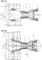
- FIG. 1A represents in a simplified manner an axial turbomachine.
- This is a dual-flow turbojet.
- the turbojet 2 comprises a first compression level, called low-pressure compressor 4, a second compression level, called high-pressure compressor 6, a combustion chamber 8 and one or more turbine levels 10.
- the mechanical power of the turbine 10 transmitted via the central shaft to the rotor 12 sets the two compressors 4 and 6 in motion.
- the latter comprise several rows of rotor blades associated with rows of stator blades.
- the rotation of the rotor about its axis of rotation 14 thus makes it possible to generate an air flow and to gradually compress the latter up to the inlet of the combustion chamber 8.
- An inlet fan commonly referred to as a fan or blower 16 is coupled to the rotor 12 via a gear train 17, and generates an air flow which is divided into a primary flow 18 passing through the various aforementioned levels of the turbomachine, and into a secondary flow 20 passing through an annular duct (partially shown) along the machine to then join the primary flow at the turbine outlet.
- the secondary flow can be accelerated so as to generate a thrust reaction necessary for the flight of an aircraft.
- the primary flow 18 and secondary flow 20 are coaxial annular flows fitted into each other.
- FIG. 1B represents an axial turbomachine 2 with an alternative architecture to that of the Figure 1A .
- the same reference numbers represent the same elements.
- the difference between the two architectures is the presence of a casing 11 carrying the reducer 17, in particular via radial arms (called “struts") 13.
- the radial arms 13 can be directly downstream of a row of stator blades 15.
- the illustrated embodiment is related to the architecture of the Figure 1A but all the technical characteristics of the invention can also be provided on a turbomachine with an architecture according to the Figure 1B .
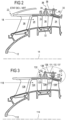
- FIG 2 is a sectional view of a compressor of an axial turbomachine such as that of the figure 1 , with an external shroud according to the state of the art.
- the compressor may be a low-pressure compressor 4.
- the rotor 12 comprises several rows of rotor blades 24. It may consist of a single-piece bladed drum or single-piece bladed discs. Alternatively, it may comprise blades with dovetail attachment.
- the low-pressure compressor 4 comprises several rectifiers, for example four, which each contain a row of stator blades 26. Some stator blades may have adjustable orientation, also called variable-pitch blades.
- the rectifiers are respectively associated with a row of rotor blades to straighten the air flow, so as to convert the speed of the flow into pressure, in particular into static pressure.
- a nozzle 22 which may have defrosting functions may be mounted on a housing which supports a row of inlet stator vanes 28.
- the stator vanes 26 extend substantially radially from an outer shroud 30 to inner rings 32.
- the vanes 26 may be secured to the outer shroud 30 by pins or journals 34.
- the shroud 30 defines an inner surface 29 that guides the gas flow.
- the compressor may have a plurality of adjacent axial sections to form the shroud 30.
- journal 34 is pivotally driven by a connecting rod 36 around the axis 38 of the journal 34.
- the connecting rod 36 is secured to the journal 34, fixed for example by a nut.
- the connecting rods of the annular row of blades 26 are all connected to a synchronizing ring 40 by means of rods 42.
- the ring 40 rests on a cylindrical or conical surface 37.
- FIG. 3 partially represents the compressor assembled from an assembly according to the invention.
- the numbers are incremented by 100 to designate technical characteristics corresponding to those of the figure 2 .
- the shell of the invention comprises a first section 130 and a second section 230.
- the sections describe an internal gas flow guiding surface 129, 229.
- the sections comprise respective flanges 131, 231 placed opposite each other to assemble the compressor.
- the first section 130 has a tubular wall 132 defining a cylindrical external surface 137.
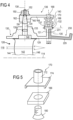
- the blade 126 comprises a vane 142 having a leading edge 144 and a trailing edge 146.
- the head of the blade 126 may comprise a shoulder 148 for centering and positioning the blade 126 in the shroud 130 as well as a groove for receiving a seal.
- the connecting rod 136 for operating the pivoting of the blade is fixed by a nut 150 on a threaded portion 152 of the head of the blade.
- a centering chamfer 154 may be provided at the end of the journal 134.
- the head of the blade is received at the right of an excess thickness of the ferrule 130, which can be in the form of a boss 133.
- the connecting rod 136 may comprise a conical orifice 160 corresponding to the chamfer 154, a body 162 and a lug 164.
- the orifice 160 may comprise a groove for receiving a key and thus making the blade 126 and the connecting rod 136 rotationally integral.
- tubular wall 132 is integral with the flange 131. Together, these form a “T” profile. Alternatively, the tubular wall may be radially spaced from the flange.
- An axis 135 schematizes the junction between the flanges 131, 231 which can be made by screwed elements.
- the cylindrical surface 137 acts as a support for pads 166 carried by the ring 140.
- a rod 168 provides the connection between the connecting rod 136 and the ring 140.
- a sleeve 170 provides the connection of the pads 166 to the rod 168 and/or to the ring 140.
- the ring 140 is in the form of a full ring or two half-rings, with a plurality of radial orifices penetrated by the rods 168. These orifices can be threaded.
- the 140 ring may have annular grooves on its upstream and downstream face in order to optimize its weight without compromising its rigidity.
- the synchronizing ring 140 cooperates with as many rods 168 as there are connecting rods 136 distributed annularly.
- the ring 140 can be actuated in pivoting about the axis 114 by suitable means such as for example a toothed wheel cooperating with a rack provided on the ring 140.
- the rack can be housed in one of the grooves of the ring 140.
- the pivoting of the ring 140 causes a corresponding movement of the rods 168 along the surface 137 and these thus pivot the connecting rods 136 and the blades 126 about their axes 138.
- the pads 166 can be directly connected to the ring 140 or to the rod 168.
- an intermediate sleeve 170 may be provided for each rod 168 and each pad 166.
- the sleeve 170 is described on the figure 5 .
- This comprises a tubular portion 172 which can be threaded on the outside to be inserted into the ring 140 and/or on the inside to receive the rod 168.
- the sleeve also comprises a rectangular portion 174 which makes it possible to hold the pad 166 by gluing, shrinking or screwing - for example using a countersunk screw 180 inserted from below and the head of which will be embedded in the pad 166.
- the portion 174 can alternatively be cylindrical to accommodate a cylindrical pad.
- the external ferrule 130 has an orifice 139 receiving the journal 134.
- the journal 134 is inserted into the orifice 139 from below (in the direction of the figure 4 ), then the connecting rod 136 is screwed using thread 52.
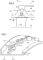
- the blade 226 is in one piece with the connecting rod 236 and the orifice of the ferrule 130 receiving the journal 234 is made of two half-orifices (139.1, 139.2 on the figure 7 ).
- Two half-sections 130.1 and 130.2 form the shroud 130.
- Each of the half-sections 130.1, 130.2 comprises a tubular wall defining an internal guide surface 129.1, 129.2 and an annular series of half-orifices 139.1, 139.2, formed in half-bosses 133.1, 133.2.
- the two half-orifices 139.1, 139.2 form the orifice 139 which receives the journal 234 of the blade 226.
- the two half-sections 130.1, 130.2 are assembled via screwed elements which hold two adjacent flanges 131.1, 131.2 together.
- the flanges 131.1, 131.2 may extend from one boss to the adjacent boss circumferentially.
- the connecting rod 236 is integral with the blade head.
- the connecting rod may be forged or cast with the rest of the blade.
- the functional surfaces (journal, extrados/intrados) are then machined.
- a welded assembly may be made. This is done before the blade is mounted in the shroud. Since the orifice 139 results from the combination of the two half-sections 130.1, 130.2, the journal 234 can be positioned in a half-orifice 139.1, 139.2 of the half-section 130.1 despite the dimension of the connecting rod which is greater than the diameter of the orifice 139, then the other half-section 130.2 is fixed to grip the journal 234 in the orifice 139.
- the synchronizing ring provided with its pads can be mounted on the second section of the shell before the blades are mounted in the half-orifices 139.1, 139.2.
- FIG. 7 represents a partial isometric view of the shell 130 of this second embodiment.
- the bosses 133.1, 133.2 as well as the flanges 131.1, 131.2 and their assembly holes can be seen (only the holes 235 of the downstream half-section 130.2 are visible).
- the flanges can completely connect each of the bosses 133.1, 133.2 to the neighboring boss.
- the upstream half-section 130.1 comprises a flange 131.3 which makes it possible to connect the shell to the compressor nozzle.
- the downstream half-section 130.2 comprises the bearing surface 137 on the tubular wall 132, which forms a “T” profile with the flange 131.
- the surface 137 is presented as cylindrical but in an unclaimed embodiment it is also possible to provide any profile for the surface 137, in particular conical or with a profile complementary to that of the pads such as in particular an external groove making it possible to guide pads provided with a pin extending radially inwards.
Landscapes
- Engineering & Computer Science (AREA)
- Mechanical Engineering (AREA)
- General Engineering & Computer Science (AREA)
- Structures Of Non-Positive Displacement Pumps (AREA)
Description
- L'invention concerne le domaine des turbomachines axiales et plus particulièrement les turboréacteurs d'aéronefs. Plus précisément, l'invention concerne un ensemble pour turbomachine axiale, notamment pour turboréacteur d'aéronef, l'ensemble comprenant une rangée annulaire d'aubes statoriques orientables, un dispositif d'actionnement du pivotement des aubes et une virole externe ayant une surface cylindrique formant un siège pour le dispositif d'actionnement.
- L'invention a également trait à une turbomachine munis d'un tel ensemble.
- Le document
US 2016/0160675 décrit une turbomachine axiale avec un agencement particulier des tourillons d'aubes statoriques à orientation variable dans une virole externe de compresseur. Le système d'actionnement de l'orientation des aubes est positionné en aval de chaque aube. Une bielle, notée 80 permet de régler le pivotement des aubes. Cette bielle peut être manipulée par une bague de synchronisation, afin que toutes les aubes d'un étage donné soient orientées de manière identique. La bague de synchronisation est aussi appelée anneau de manœuvre, bague d'actionnement ou bague de commande. Une telle bague peut parfois reposer à même la virole externe. - Une telle conception est possible dans le système du document cité ci-dessus qui comprend plusieurs étages de compression à calage variable avec une virole externe s'étendant sur plusieurs de ces étages. Une telle virole est encombrante. Dans un compresseur avec une plus courte virole ou moins d'étages de compression, un tel mécanisme est inutilement encombrant.
-
EP 0 636 766 A1 ,US 4 130 375 A ,GB 805 015 A US 3 314 654 A etWO 2014/143445 A2 divulguent d'autres exemples de dispositifs d'aubes statoriques orientables. - L'invention a pour objectif de résoudre au moins un des problèmes posés par l'art antérieur. L'invention a également pour objectif de proposer une conception plus simple et plus compacte, permettant un montage plus aisé des aubes à orientation variable et du mécanisme d'actionnement de l'orientation. L'invention a également pour objectif de proposer une solution légère.
- L'invention a pour objet un ensemble selon la revendication 1.
- Par « virole », on entend une pièce sensiblement de révolution autour d'un axe. Les tronçons axiaux de virole sont des portions d'une virole.
- Ainsi, la surface cylindrique entoure les brides et rend l'ensemble plus compact.
- Selon des modes avantageux de l'invention, l'ensemble peut comprendre une ou plusieurs des caractéristiques suivantes, prises isolément ou selon toutes les combinaisons techniques possibles :
- La paroi tubulaire et la bride du premier tronçon forment un profil en « T ».
- La paroi tubulaire et la bride du premier tronçon sont venus de matière.
- La bague peut être en contact direct ou indirect avec la surface cylindrique.
- L'ensemble comprend des patins aptes à être fixés à la bague et aptes à venir au contact de la surface cylindrique.
- L'ensemble comprend des manchons comprenant chacun une portion tubulaire pour coopérer avec une tige ou avec la bague, et une portion cylindrique ou rectangulaire pour coopérer avec un patin.
- L'ensemble comprend une pluralité de couples vis-écrous, les brides comprenant des orifices pouvant être traversés par les vis pour maintenir les tronçons entre eux par assemblage vissé.
- Les orifices sont axiaux et tels que, une fois l'ensemble assemblé, les écrous sont parallèles à la surface cylindrique.
- Au moins une de brides et/ou la paroi tubulaire et/ou les tronçons est/sont composés d'un alliage de titane, d'aluminium ou de magnésium et/ou de matériau composite.
- Le premier tronçon est réalisé à partir d'un assemblage de deux demi-tronçons, chacun des demi-tronçons comprenant une rangée annulaire de demi-orifices radiaux semi-cylindriques, les demi-orifices étant agencés pour permettre à chacun des demi-orifices d'un demi-tronçon d'être mis en correspondance axiale et circonférentielle avec un demi-orifice de l'autre demi-tronçon pour former la rangée annulaire d'orifices radiaux.
- Les demi-tronçons sont assemblés à l'aide de brides respectives positionnées circonférentiellement entre deux demi-orifices adjacents, chaque espacement circonférentiel entre deux demi-orifices adjacents contenant une des brides.
- Les brides sont des flancs s'étendant perpendiculairement à l'axe de symétrie de la virole et ayant une épaisseur axiale, la surface cylindrique s'étendant axialement sur une longueur de plus de trois fois la somme des épaisseurs axiales des deux brides.
- L'invention porte également sur une turbomachine axiale, notamment un turboréacteur d'aéronef, avec un compresseur basse-pression, un compresseur haute-pression et une veine intermédiaire entre le compresseur basse-pression et le compresseur haute-pression, remarquable en ce que le compresseur basse-pression, la veine intermédiaire et/ou le compresseur haute-pression comprend/comprennent un ensemble tel que décrit ci-dessus.
- Dans un mode de réalisation non revendiqué est défini un procédé d'assemblage d'un tel ensemble à l'aide d'un tel kit, le procédé comprenant les étapes suivantes : l'introduction des têtes des aubes dans les orifices radiaux du premier tronçon ; l'assemblage des patins, des tiges et des bielles à la bague ; l'assemblage d'une bielle de manœuvre à la tête de chaque aube ; la fixation, préférentiellement par vissage, des brides des deux tronçons entre elles.
- Selon un mode avantageux, le procédé comprend une étape d'assemblage des demi-tronçons réalisée après l'étape d'assemblage des bielles aux aubes.
- L'invention propose une géométrie spécifique qui est particulièrement compacte. De plus, le positionnement de la surface cylindrique au-dessus des brides permet une bonne rigidité du siège du dispositif d'actionnement.
-
- Les
figures 1A et 1B représentent une turbomachine axiale ; - La
figure 2 est un schéma d'un compresseur de turbomachine selon l'état de la technique ; - Les
figures 3 et4 montrent respectivement un compresseur avec une virole et une partie agrandie de la virole, selon l'invention ; - La
figure 5 illustre un manchon qui peut être utilisé dans l'ensemble selon l'invention ; - La
figure 6 est une coupe d'une aube avec une bielle monobloc utilisée dans un second mode de réalisation de l'invention ; - La
figure 7 est une vue isométrique partielle du premier tronçon dans ce deuxième mode de réalisation. - Dans la description qui va suivre, les termes « interne » et « externe » renvoient à un positionnement par rapport à l'axe de rotation d'une turbomachine axiale. La direction axiale correspond à la direction le long de l'axe de rotation de la turbomachine. La direction radiale est perpendiculaire à l'axe de rotation. L'amont et l'aval sont en référence au sens d'écoulement principal du flux dans la turbomachine.
- La
figure 1A représente de manière simplifiée une turbomachine axiale. Il s'agit ici d'un turboréacteur double-flux. Le turboréacteur 2 comprend un premier niveau de compression, dit compresseur basse-pression 4, un deuxième niveau de compression, dit compresseur haute-pression 6, une chambre de combustion 8 et un ou plusieurs niveaux de turbines 10. En fonctionnement, la puissance mécanique de la turbine 10 transmise via l'arbre central jusqu'au rotor 12 met en mouvement les deux compresseurs 4 et 6. Ces derniers comportent plusieurs rangées d'aubes de rotor associées à des rangées d'aubes de stator. La rotation du rotor autour de son axe de rotation 14 permet ainsi de générer un débit d'air et de comprimer progressivement ce dernier jusqu'à l'entrée de la chambre de combustion 8. - Un ventilateur d'entrée communément désigné fan ou soufflante 16 est couplé au rotor 12 via un train d'engrenage 17, et génère un flux d'air qui se divise en un flux primaire 18 traversant les différents niveaux susmentionnés de la turbomachine, et en un flux secondaire 20 traversant un conduit annulaire (partiellement représenté) le long de la machine pour ensuite rejoindre le flux primaire en sortie de turbine.
- Le flux secondaire peut être accéléré de sorte à générer une réaction de poussée nécessaire au vol d'un avion. Les flux primaire 18 et secondaire 20 sont des flux annulaires coaxiaux et emmanchés l'un dans l'autre.
- La
figure 1B représente une turbomachine axiale 2 avec une architecture alternative à celle de lafigure 1A . Les mêmes numéros de référence représentent les mêmes éléments. La différence entre les deux architectures est la présence d'un carter 11 portant le réducteur 17, notamment via des bras radiaux (dits « struts ») 13. Les bras radiaux 13 peuvent être directement en aval d'une rangée d'aubes statoriques 15. - Dans la suite, le mode de réalisation illustré est en rapport avec l'architecture de la
figure 1A mais toutes les caractéristiques techniques de l'invention peuvent également être prévue sur une turbomachine avec une architecture selon lafigure 1B . - La
figure 2 est une vue en coupe d'un compresseur d'une turbomachine axiale telle que celle de lafigure 1 , avec une virole externe selon l'état de l'art. Le compresseur peut être un compresseur basse-pression 4. Le rotor 12 comprend plusieurs rangées d'aubes rotoriques 24. Il peut être constitué d'un tambour monobloc aubagé ou de disques aubagés monoblocs. Alternativement il peut comprendre des aubes à fixation par queue d'aronde. - Le compresseur basse-pression 4 comprend plusieurs redresseurs, par exemple quatre, qui contiennent chacun une rangée d'aubes statoriques 26. Certaines aubes statoriques peuvent être à orientation réglable, également appelé aubes à calage variable. Les redresseurs sont associés respectivement à une rangée d'aubes rotoriques pour redresser le flux d'air, de sorte à convertir la vitesse du flux en pression, notamment en pression statique.
- Un bec 22 qui peut avoir des fonctions de dégivrage peut être monté sur un carter qui supporte une rangée d'aubes statoriques d'entrée 28.
- Les aubes statoriques 26 s'étendent essentiellement radialement depuis une virole externe 30 vers des anneaux internes 32. Les aubes 26 peuvent être fixées à la virole externe 30 à l'aide d'axes ou tourillons 34. La virole 30 définit une surface interne 29 qui guide le flux de gaz. Le compresseur peut comporter plusieurs tronçons axiaux adjacents pour former la virole 30.
- Dans cet exemple, le tourillon 34 est entraîné en pivotement par une bielle 36 autour de l'axe 38 du tourillon 34. La bielle 36 est solidaire du tourillon 34, fixée par exemple par un écrou.
- Les bielles de la rangée annulaire d'aubes 26 sont toutes reliées à une bague de synchronisation 40 au moyen de tiges 42.
- La bague 40 repose sur une surface cylindrique ou conique 37.
- La
figure 3 représente partiellement le compresseur assemblé à partir d'un ensemble selon l'invention. Les numéros sont incrémentés de 100 pour désigner des caractéristiques techniques correspondant à celles de lafigure 2 . - En comparaison de la
figure 2 , la virole de l'invention comprend un premier tronçon 130 et un second tronçon 230. Les tronçons décrivent une surface interne de guidage du flux de gaz 129, 229. Les tronçons comprennent des brides respectives 131, 231 mises en regard pour assembler le compresseur. - Le premier tronçon 130 dispose d'une paroi tubulaire 132 définissant une surface externe cylindrique 137.
- Plus de détails à ce sujet sont donnés sur la
figure 4 qui est un agrandissement de la zone de lafigure 3 entourée en pointillés. - L'aube 126 comprend une pale 142 présentant un bord d'attaque 144 et un bord de fuite 146. La tête de l'aube 126 peut comprendre un épaulement 148 pour le centrage et la mise en position de l'aube 126 dans la virole 130 ainsi qu'une gorge pour recevoir un joint d'étanchéité. La bielle 136 de manœuvre du pivotement de l'aube est fixée par un écrou 150 sur une portion filetée 152 de la tête de l'aube. Un chanfrein de centrage 154 peut être prévu à l'extrémité du tourillon 134.
- La tête de l'aube est reçue au droit d'une surépaisseur de la virole 130, qui peut être sous la forme d'un bossage 133.
- La bielle 136 peut comprendre un orifice conique 160 correspondant au chanfrein 154, un corps 162 et une patte 164. L'orifice 160 peut comprendre une rainure pour recevoir une clavette et ainsi rendre solidaire en rotation l'aube 126 et la bielle 136.
- Dans cet exemple, la paroi tubulaire 132 est venue de matière avec la bride 131. Ceux-ci forment ensemble un profil en « T ». Alternativement, la paroi tubulaire peut être radialement distante de la bride.
- Un axe 135 schématise la jonction entre les brides 131, 231 qui peut être faite par éléments vissés.
- La surface cylindrique 137 fait office de support pour des patins 166 portés par la bague 140.
- Une tige 168 assure la liaison entre la bielle 136 et la bague 140. Un manchon 170 assure la connexion des patins 166 à la tige 168 et/ou à la bague 140.
- La bague 140 se présente sous la forme d'un anneau plein ou de deux demi-anneaux, avec une pluralité d'orifices radiaux pénétrés par les tiges 168. Ces orifices peuvent être filetés.
- La bague 140 peut présenter des gorges annulaires sur sa face amont et aval afin d'optimiser son poids sans compromettre sa rigidité.
- La bague de synchronisation 140 coopère avec autant de tiges 168 que de bielles 136 réparties annulairement. La bague 140 peut être actionnée en pivotement autour de l'axe 114 par des moyens appropriés comme par exemple une roue dentée coopérant avec une crémaillère prévue sur la bague 140. La crémaillère peut être logée dans une des gorges de la bague 140. Le pivotement de la bague 140 entraîne un déplacement correspondant des tiges 168 le long de la surface 137 et celles-ci font ainsi pivoter les bielles 136 et les aubes 126 autour de leurs axes 138.
- Les patins 166 peuvent être directement connectés à la bague 140 ou à la tige 168.
- Alternativement, un manchon intermédiaire 170 peut être prévu pour chaque tige 168 et chaque patin 166.
- Le manchon 170 est décrit sur la
figure 5 . Celui-ci comprend une portion tubulaire 172 qui peut être filetée à l'extérieure pour être insérée dans la bague 140 et/ou à l'intérieur pour recevoir la tige 168. Le manchon comprend également une portion rectangulaire 174 qui permet de maintenir le patin 166 par collage, frettage ou vissage - par exemple à l'aide d'une vis fraisée 180 insérée par en-dessous et dont la tête sera noyée dans le patin 166. La portion 174 peut alternativement être cylindrique pour accueillir un patin cylindrique. - Dans l'exemple des
figures 4 et 5 , la virole externe 130 présente un orifice 139 recevant le tourillon 134. Le tourillon 134 est inséré dans l'orifice 139 par le bas (dans le sens de lafigure 4 ), puis la bielle 136 est vissée à l'aide du filet 52. - Les
figures 6 et 7 montrent un agencement différent. Celles-ci sont décrites ensemble dans les paragraphes qui suivent. Les numéros de références de l'aube et de la bielle sont indexés de 100 par rapport au mode de réalisation desfigures 3 à 5 . - L'aube 226 est monobloc avec la bielle 236 et l'orifice de la virole 130 recevant le tourillon 234 est fait de deux demi-orifices (139.1, 139.2 sur la
figure 7 ). - Deux demi-tronçons 130.1 et 130.2 forment la virole 130. Chacun des demi-tronçons 130.1, 130.2 comprend une paroi tubulaire définissant une surface interne de guidage 129.1, 129.2 et une série annulaire de demi-orifices 139.1, 139.2, formés dans des demi-bossages 133.1, 133.2. Les deux demi-orifices 139.1, 139.2 forment l'orifice 139 qui reçoit le tourillon 234 de l'aube 226. Les deux demi-tronçons 130.1, 130.2 sont assemblés via des éléments vissés qui maintiennent deux brides 131.1, 131.2 adjacentes ensemble. Les brides 131.1, 131.2 peuvent s'étendre d'un bossage au bossage voisin circonférentiellement. La bielle 236 est venue de matière avec la tête de l'aube. Par exemple, la bielle peut être forgée ou moulée avec le reste de l'aube. Les surfaces fonctionnelles (tourillon, extrados/intrados) sont ensuite usinées. Alternativement, un assemblage soudé peut être réalisé. Ceci est effectué avant le montage de l'aube dans la virole. Comme l'orifice 139 résulte de la combinaison des deux demi-tronçons 130.1, 130.2, le tourillon 234 peut être positionné dans un demi-orifice 139.1, 139.2 du demi-tronçon 130.1 malgré la dimension de la bielle qui est supérieure au diamètre de l'orifice 139, puis l'autre demi-tronçon 130.2 est fixé pour enserrer le tourillon 234 dans l'orifice 139. La bague de synchronisation munie de ses patins peut être montée sur le second tronçon de virole avant que les aubes ne soient montées dans les demi-orifices 139.1, 139.2.
- La
figure 7 représente une vue partielle isométrique de la virole 130 de ce deuxième mode de réalisation. On y voit notamment quelques-uns des bossages 133.1, 133.2 ainsi que des brides 131.1, 131.2 et leurs trous d'assemblage (seuls les trous 235 du demi-tronçon aval 130.2 sont visibles). Les brides peuvent relier complètement chacun des bossages 133.1, 133.2 au bossage voisin. Le demi-tronçon amont 130.1 comprend une bride 131.3 qui permet de connecter la virole au bec du compresseur. Le demi-tronçon aval 130.2 comprend la surface d'appui 137 sur la paroi tubulaire 132, qui forme un profil en « T » avec la bride 131. - Dans les exemples illustrés, la surface 137 est présentée comme cylindrique mais dans un mode de réalisation non revendiqué il est également possible de prévoir tout profil pour la surface 137, notamment conique ou avec un profil complémentaire à celui des patins comme notamment une gorge externe permettant de guider des patins munis d'un pion s'étendant radialement vers l'intérieur.
Claims (12)
- Ensemble pour turbomachine axiale (2), notamment pour turboréacteur d'aéronef, l'ensemble comprenant :- une rangée annulaire d'aubes statoriques (126) avec chacune une pale (142) et une tête radiale (134, 148, 154) contenant un tourillon cylindrique (134) ; les aubes (126) étant orientables par pivotement autour de l'axe du tourillon (138) ;- un dispositif d'actionnement (136, 140, 166, 168, 170) du pivotement des aubes (126) comprenant une bague de synchronisation (140) et des bielles de manœuvre (136) reliant la bague de synchronisation (140) à chacune des aubes (126) ;- une virole externe (130, 230) comprenant une paroi tubulaire et présentant une rangée annulaire d'orifices radiaux (139) pour recevoir les têtes (134, 148, 154) des aubes (126) ;la virole (130, 230) comprenant deux tronçons (130, 230) tubulaires axialement adjacents, les tronçons (130, 230) étant assemblés au moyen de brides (131, 231) respectives, caractérisé en ce que le premier tronçon (130) comprend une surface cylindrique (137) coaxiale au tronçon (130) et forme un siège pour le dispositif d'actionnement (136, 140, 166, 168, 170), et en ce que la surface cylindrique (137) est une surface externe d'une paroi tubulaire (132) chevauchant axialement les deux brides (131, 231).
- Ensemble selon la revendication 1, caractérisé en ce que la paroi tubulaire (132) et la bride (131) du premier tronçon (130) forment un profil en « T ».
- Ensemble selon l'une des revendications 1 ou 2, caractérisé en ce que la paroi tubulaire (132) et la bride (131) du premier tronçon (130) sont venus de matière.
- Ensemble selon l'une des revendications 1 à 3, caractérisé en ce qu'il comprend des patins (166) fixés à la bague (140) et venant au contact de la surface cylindrique (137).
- Ensemble selon la revendication précédente, caractérisé en ce qu'il comprend des manchons (170) comprenant chacun une portion tubulaire (172) pour coopérer avec une tige (168) ou avec la bague (140), et une portion rectangulaire (174) ou cylindrique pour coopérer avec un patin (166).
- Ensemble selon l'une des revendications 1 à 5, caractérisé en ce qu'il comprend une pluralité de couples vis-écrous, les brides (131, 231) comprenant des orifices pouvant être traversés par les vis pour maintenir les tronçons (130, 230) entre eux par assemblage vissé.
- Ensemble selon la revendication précédente, caractérisé en que les orifices sont axiaux et les écrous sont parallèles à la surface cylindrique (137).
- Ensemble selon l'une des revendications 1 à 7, caractérisé en ce qu'au moins une de brides (131, 231) et/ou la paroi tubulaire (132) et/ou les tronçons (130, 230) est/sont composés d'un alliage de titane, d'aluminium ou de magnésium et/ou de matériau composite.
- Ensemble selon l'une des revendications 1 à 8, caractérisé en ce que le premier tronçon (130) est réalisé à partir d'un assemblage de deux demi-tronçons (130.1, 130.2), chacun des demi-tronçons (130.1, 130.2) comprenant une rangée annulaire de demi-orifices (139.1, 139.2) radiaux semi-cylindriques ; les demi-orifices (139.1, 139.2) étant agencés pour permettre à chacun des demi-orifices (139.1, 139.2) d'un demi-tronçon (130.1, 130.2) d'être mis en correspondance axiale et circonférentielle avec un demi-orifice (139.1, 139.2) de l'autre demi-tronçon (130.1, 130.2) pour former la rangée annulaire d'orifices radiaux (139).
- Ensemble selon la revendication précédente, caractérisé en ce que les demi-tronçons (130.1, 130.2) sont assemblés à l'aide de brides (131.1, 131.2) respectives positionnées circonférentiellement entre deux demi-orifices adjacents (139.1, 139.2), chaque espacement circonférentiel entre deux demi-orifices (139.1, 139.2) adjacents contenant une des brides (131.1, 131.2).
- Ensemble selon l'une des revendications 1 à 10, caractérisé en ce que les brides (131, 231) sont des flancs s'étendant perpendiculairement à l'axe (114) de symétrie de la virole et ayant une épaisseur axiale (E1, E2), la surface cylindrique (137) s'étendant axialement sur une longueur (L) de plus de trois fois la somme des épaisseurs axiales (E1, E2) des deux brides (131, 231).
- Turbomachine axiale (2), notamment un turboréacteur d'aéronef, avec un compresseur basse-pression (4), un compresseur haute-pression (6) et une veine intermédiaire entre le compresseur basse-pression (4) et le compresseur haute-pression (6), caractérisée en ce que le compresseur basse-pression (4), la veine intermédiaire et/ou le compresseur haute-pression (6) comprend/comprennent un ensemble selon l'une des revendications 1 ou 11.
Applications Claiming Priority (2)
| Application Number | Priority Date | Filing Date | Title |
|---|---|---|---|
| BE20185429A BE1026411B1 (fr) | 2018-06-21 | 2018-06-21 | Virole extérieure de turbomachine |
| PCT/EP2019/066318 WO2019243484A1 (fr) | 2018-06-21 | 2019-06-20 | Virole extérieure de turbomachine |
Publications (2)
| Publication Number | Publication Date |
|---|---|
| EP3810903A1 EP3810903A1 (fr) | 2021-04-28 |
| EP3810903B1 true EP3810903B1 (fr) | 2025-02-12 |
Family
ID=62985847
Family Applications (1)
| Application Number | Title | Priority Date | Filing Date |
|---|---|---|---|
| EP19731293.7A Active EP3810903B1 (fr) | 2018-06-21 | 2019-06-20 | Virole extérieure de turbomachine |
Country Status (5)
| Country | Link |
|---|---|
| US (1) | US11236634B2 (fr) |
| EP (1) | EP3810903B1 (fr) |
| CN (1) | CN111051652B (fr) |
| BE (1) | BE1026411B1 (fr) |
| WO (1) | WO2019243484A1 (fr) |
Families Citing this family (5)
| Publication number | Priority date | Publication date | Assignee | Title |
|---|---|---|---|---|
| BE1026199B1 (fr) * | 2018-04-10 | 2019-11-12 | Safran Aero Boosters S.A. | Virole exterieure en deux parties |
| BE1027280B1 (fr) | 2019-05-16 | 2020-12-15 | Safran Aero Boosters Sa | Carter de compresseur pour turbomachine |
| DE102021121462A1 (de) | 2021-08-18 | 2023-02-23 | MTU Aero Engines AG | Verstellbare Leitschaufel für eine Gasturbine, Gasturbine und Verfahren zur Montage einer verstellbaren Leitschaufel für eine Gasturbine |
| EP4534806A1 (fr) | 2023-10-02 | 2025-04-09 | Safran Aero Boosters | Dispositif de commande de calage d'aubes d'une grille d'aubes à calage variable de turbomachine d'aéronef |
| BE1032726B1 (fr) * | 2024-06-28 | 2026-02-03 | Safran Aero Boosters | Ensemble redresseur pour compresseur basse pression de turbomachine |
Family Cites Families (20)
| Publication number | Priority date | Publication date | Assignee | Title |
|---|---|---|---|---|
| BE514728A (fr) * | 1951-10-10 | |||
| NL198161A (fr) * | 1955-06-17 | |||
| US3314654A (en) * | 1965-07-30 | 1967-04-18 | Gen Electric | Variable area turbine nozzle for axial flow gas turbine engines |
| CA1034509A (fr) * | 1975-10-14 | 1978-07-11 | Westinghouse Canada Limited | Commande de roue a aubes pour turbine a gaz |
| US4363600A (en) * | 1981-04-06 | 1982-12-14 | General Motors Corporation | Variable vane mounting |
| GB2210935B (en) * | 1987-10-10 | 1992-05-27 | Rolls Royce Plc | Variable stator vane assembly |
| US4834613A (en) * | 1988-02-26 | 1989-05-30 | United Technologies Corporation | Radially constrained variable vane shroud |
| FR2708311B1 (fr) * | 1993-07-28 | 1995-09-01 | Snecma | Stator de turbomachine à aubes pivotantes et anneau de commande. |
| DE10161292A1 (de) * | 2001-12-13 | 2003-06-26 | Rolls Royce Deutschland | Lagerring zur Lagerung von Schaufelfüßen von verstellbaren Statorschaufeln im Hochdruckverdichter einer Gasturbine |
| US7510369B2 (en) * | 2005-09-02 | 2009-03-31 | United Technologies Corporation | Sacrificial inner shroud liners for gas turbine engines |
| FR2922257B1 (fr) * | 2007-10-12 | 2014-03-28 | Snecma | Perfectionnement a un anneau de commande de calage des aubes fixes d'une turbomachine |
| WO2014143445A2 (fr) * | 2013-02-10 | 2014-09-18 | United Technologies Corporation | Enveloppe de recouvrement d'aube fixe à incidence variable |
| US10125789B2 (en) * | 2013-02-15 | 2018-11-13 | United Technologies Corporation | Bushing arranged between a body and a shaft, and connected to the body |
| FR3007069B1 (fr) * | 2013-06-12 | 2015-07-17 | Snecma | Tourillon pour turbine haute pression, et turboreacteur incluant un tel tourillon |
| FR3014152B1 (fr) * | 2013-11-29 | 2015-12-25 | Snecma | Dispositif de guidage d'aubes de redresseur a angle de calage variable de turbomachine et procede d'assemblage d'un tel dispositif |
| JP6118721B2 (ja) * | 2013-12-20 | 2017-04-19 | 株式会社Ihi | ファンケース及びファンケースの製造方法 |
| BE1022364B1 (fr) * | 2014-10-27 | 2016-03-17 | Techspace Aero S.A. | Compresseur de turbomachine axiale avec double rotors contrarotatifs |
| US10047765B2 (en) * | 2014-12-03 | 2018-08-14 | General Electric Company | Bushing for a variable stator vane and method of making same |
| US20180045218A1 (en) * | 2016-08-11 | 2018-02-15 | United Technologies Corporation | Shim for gas turbine engine |
| US10526911B2 (en) * | 2017-06-22 | 2020-01-07 | United Technologies Corporation | Split synchronization ring for variable vane assembly |
-
2018
- 2018-06-21 BE BE20185429A patent/BE1026411B1/fr active IP Right Grant
-
2019
- 2019-06-20 US US16/650,622 patent/US11236634B2/en active Active
- 2019-06-20 WO PCT/EP2019/066318 patent/WO2019243484A1/fr not_active Ceased
- 2019-06-20 CN CN201980004144.5A patent/CN111051652B/zh active Active
- 2019-06-20 EP EP19731293.7A patent/EP3810903B1/fr active Active
Also Published As
| Publication number | Publication date |
|---|---|
| EP3810903A1 (fr) | 2021-04-28 |
| CN111051652A (zh) | 2020-04-21 |
| CN111051652B (zh) | 2022-08-09 |
| BE1026411A1 (fr) | 2020-01-23 |
| WO2019243484A1 (fr) | 2019-12-26 |
| BE1026411B1 (fr) | 2020-01-30 |
| US20200392862A1 (en) | 2020-12-17 |
| US11236634B2 (en) | 2022-02-01 |
Similar Documents
| Publication | Publication Date | Title |
|---|---|---|
| EP4453399A1 (fr) | Module de turbomachine equipe d'aubes a calage variable et d'une virole annulaire d'interface | |
| BE1026411B1 (fr) | Virole extérieure de turbomachine | |
| EP4185767B1 (fr) | Module de turbomachine equipe d'une helice et d'aubes de stator supportees par des moyens de maintien et turbomachine correspondante | |
| EP4222052B1 (fr) | Module de turbomachine equipe d'une helice et d'aubes de stator portees par deux carters et turbomachine correspondante | |
| EP4222355A1 (fr) | Module de turbomachine equipe d'une helice et d'aubes de stator deportees | |
| EP3091201A1 (fr) | Bec de séparation composite de compresseur de turbomachine axiale | |
| EP4143421B1 (fr) | Carter intermediaire de redressement avec bras structural monobloc | |
| EP3412876B1 (fr) | Compresseur a géométrie variable de turbomachine axiale | |
| EP4077880B1 (fr) | Module pour turbomachine | |
| EP3553322B1 (fr) | Ensemble pour turbomachine axiale avec virole exterieure en deux parties | |
| EP3290657B1 (fr) | Stator à aubes ajustables pour compresseur de turbomachine axiale | |
| EP3382242B1 (fr) | Joint à brosse pour rotor de turbomachine | |
| WO2017187093A1 (fr) | Ensemble de redressement de flux d'air et turbomachine comprenant un tel ensemble | |
| BE1025131B1 (fr) | Arbre de transmission à double cannelure pour turbomachine | |
| FR3109796A1 (fr) | Carter intermediaire de redressement avec bras structural rapporte | |
| EP3715638B1 (fr) | Rotor hybride à coquille externe rapportée contre la paroi annulaire composite | |
| BE1025984B1 (fr) | Veine de compresseur basse-pression pour turbomachine | |
| FR3135747A1 (fr) | Ensemble propulsif pour un aeronef | |
| BE1023031B1 (fr) | Bec de separation composite de compresseur de turbomachine axiale |
Legal Events
| Date | Code | Title | Description |
|---|---|---|---|
| STAA | Information on the status of an ep patent application or granted ep patent |
Free format text: STATUS: UNKNOWN |
|
| STAA | Information on the status of an ep patent application or granted ep patent |
Free format text: STATUS: THE INTERNATIONAL PUBLICATION HAS BEEN MADE |
|
| PUAI | Public reference made under article 153(3) epc to a published international application that has entered the european phase |
Free format text: ORIGINAL CODE: 0009012 |
|
| STAA | Information on the status of an ep patent application or granted ep patent |
Free format text: STATUS: REQUEST FOR EXAMINATION WAS MADE |
|
| 17P | Request for examination filed |
Effective date: 20200210 |
|
| AK | Designated contracting states |
Kind code of ref document: A1 Designated state(s): AL AT BE BG CH CY CZ DE DK EE ES FI FR GB GR HR HU IE IS IT LI LT LU LV MC MK MT NL NO PL PT RO RS SE SI SK SM TR |
|
| AX | Request for extension of the european patent |
Extension state: BA ME |
|
| DAV | Request for validation of the european patent (deleted) | ||
| DAX | Request for extension of the european patent (deleted) | ||
| STAA | Information on the status of an ep patent application or granted ep patent |
Free format text: STATUS: EXAMINATION IS IN PROGRESS |
|
| 17Q | First examination report despatched |
Effective date: 20230323 |
|
| GRAP | Despatch of communication of intention to grant a patent |
Free format text: ORIGINAL CODE: EPIDOSNIGR1 |
|
| STAA | Information on the status of an ep patent application or granted ep patent |
Free format text: STATUS: GRANT OF PATENT IS INTENDED |
|
| INTG | Intention to grant announced |
Effective date: 20240830 |
|
| GRAS | Grant fee paid |
Free format text: ORIGINAL CODE: EPIDOSNIGR3 |
|
| GRAA | (expected) grant |
Free format text: ORIGINAL CODE: 0009210 |
|
| STAA | Information on the status of an ep patent application or granted ep patent |
Free format text: STATUS: THE PATENT HAS BEEN GRANTED |
|
| AK | Designated contracting states |
Kind code of ref document: B1 Designated state(s): AL AT BE BG CH CY CZ DE DK EE ES FI FR GB GR HR HU IE IS IT LI LT LU LV MC MK MT NL NO PL PT RO RS SE SI SK SM TR |
|
| REG | Reference to a national code |
Ref country code: GB Ref legal event code: FG4D Free format text: NOT ENGLISH |
|
| REG | Reference to a national code |
Ref country code: CH Ref legal event code: EP |
|
| REG | Reference to a national code |
Ref country code: DE Ref legal event code: R096 Ref document number: 602019065764 Country of ref document: DE |
|
| REG | Reference to a national code |
Ref country code: IE Ref legal event code: FG4D Free format text: LANGUAGE OF EP DOCUMENT: FRENCH |
|
| REG | Reference to a national code |
Ref country code: NL Ref legal event code: MP Effective date: 20250212 |
|
| PG25 | Lapsed in a contracting state [announced via postgrant information from national office to epo] |
Ref country code: RS Free format text: LAPSE BECAUSE OF FAILURE TO SUBMIT A TRANSLATION OF THE DESCRIPTION OR TO PAY THE FEE WITHIN THE PRESCRIBED TIME-LIMIT Effective date: 20250512 |
|
| PG25 | Lapsed in a contracting state [announced via postgrant information from national office to epo] |
Ref country code: FI Free format text: LAPSE BECAUSE OF FAILURE TO SUBMIT A TRANSLATION OF THE DESCRIPTION OR TO PAY THE FEE WITHIN THE PRESCRIBED TIME-LIMIT Effective date: 20250212 |
|
| PG25 | Lapsed in a contracting state [announced via postgrant information from national office to epo] |
Ref country code: PL Free format text: LAPSE BECAUSE OF FAILURE TO SUBMIT A TRANSLATION OF THE DESCRIPTION OR TO PAY THE FEE WITHIN THE PRESCRIBED TIME-LIMIT Effective date: 20250212 |
|
| PGFP | Annual fee paid to national office [announced via postgrant information from national office to epo] |
Ref country code: DE Payment date: 20250618 Year of fee payment: 7 |
|
| PG25 | Lapsed in a contracting state [announced via postgrant information from national office to epo] |
Ref country code: ES Free format text: LAPSE BECAUSE OF FAILURE TO SUBMIT A TRANSLATION OF THE DESCRIPTION OR TO PAY THE FEE WITHIN THE PRESCRIBED TIME-LIMIT Effective date: 20250212 |
|
| PGFP | Annual fee paid to national office [announced via postgrant information from national office to epo] |
Ref country code: GB Payment date: 20250625 Year of fee payment: 7 |
|
| REG | Reference to a national code |
Ref country code: LT Ref legal event code: MG9D |
|
| PG25 | Lapsed in a contracting state [announced via postgrant information from national office to epo] |
Ref country code: IS Free format text: LAPSE BECAUSE OF FAILURE TO SUBMIT A TRANSLATION OF THE DESCRIPTION OR TO PAY THE FEE WITHIN THE PRESCRIBED TIME-LIMIT Effective date: 20250612 Ref country code: NO Free format text: LAPSE BECAUSE OF FAILURE TO SUBMIT A TRANSLATION OF THE DESCRIPTION OR TO PAY THE FEE WITHIN THE PRESCRIBED TIME-LIMIT Effective date: 20250512 |
|
| PG25 | Lapsed in a contracting state [announced via postgrant information from national office to epo] |
Ref country code: NL Free format text: LAPSE BECAUSE OF FAILURE TO SUBMIT A TRANSLATION OF THE DESCRIPTION OR TO PAY THE FEE WITHIN THE PRESCRIBED TIME-LIMIT Effective date: 20250212 |
|
| PGFP | Annual fee paid to national office [announced via postgrant information from national office to epo] |
Ref country code: BE Payment date: 20250624 Year of fee payment: 7 |
|
| PG25 | Lapsed in a contracting state [announced via postgrant information from national office to epo] |
Ref country code: HR Free format text: LAPSE BECAUSE OF FAILURE TO SUBMIT A TRANSLATION OF THE DESCRIPTION OR TO PAY THE FEE WITHIN THE PRESCRIBED TIME-LIMIT Effective date: 20250212 |
|
| PG25 | Lapsed in a contracting state [announced via postgrant information from national office to epo] |
Ref country code: PT Free format text: LAPSE BECAUSE OF FAILURE TO SUBMIT A TRANSLATION OF THE DESCRIPTION OR TO PAY THE FEE WITHIN THE PRESCRIBED TIME-LIMIT Effective date: 20250612 Ref country code: LV Free format text: LAPSE BECAUSE OF FAILURE TO SUBMIT A TRANSLATION OF THE DESCRIPTION OR TO PAY THE FEE WITHIN THE PRESCRIBED TIME-LIMIT Effective date: 20250212 |
|
| PGFP | Annual fee paid to national office [announced via postgrant information from national office to epo] |
Ref country code: FR Payment date: 20250623 Year of fee payment: 7 |
|
| PG25 | Lapsed in a contracting state [announced via postgrant information from national office to epo] |
Ref country code: BG Free format text: LAPSE BECAUSE OF FAILURE TO SUBMIT A TRANSLATION OF THE DESCRIPTION OR TO PAY THE FEE WITHIN THE PRESCRIBED TIME-LIMIT Effective date: 20250212 Ref country code: GR Free format text: LAPSE BECAUSE OF FAILURE TO SUBMIT A TRANSLATION OF THE DESCRIPTION OR TO PAY THE FEE WITHIN THE PRESCRIBED TIME-LIMIT Effective date: 20250513 |
|
| REG | Reference to a national code |
Ref country code: AT Ref legal event code: MK05 Ref document number: 1766209 Country of ref document: AT Kind code of ref document: T Effective date: 20250212 |
|
| PG25 | Lapsed in a contracting state [announced via postgrant information from national office to epo] |
Ref country code: SE Free format text: LAPSE BECAUSE OF FAILURE TO SUBMIT A TRANSLATION OF THE DESCRIPTION OR TO PAY THE FEE WITHIN THE PRESCRIBED TIME-LIMIT Effective date: 20250212 |
|
| PG25 | Lapsed in a contracting state [announced via postgrant information from national office to epo] |
Ref country code: SM Free format text: LAPSE BECAUSE OF FAILURE TO SUBMIT A TRANSLATION OF THE DESCRIPTION OR TO PAY THE FEE WITHIN THE PRESCRIBED TIME-LIMIT Effective date: 20250212 |
|
| PG25 | Lapsed in a contracting state [announced via postgrant information from national office to epo] |
Ref country code: DK Free format text: LAPSE BECAUSE OF FAILURE TO SUBMIT A TRANSLATION OF THE DESCRIPTION OR TO PAY THE FEE WITHIN THE PRESCRIBED TIME-LIMIT Effective date: 20250212 |
|
| PG25 | Lapsed in a contracting state [announced via postgrant information from national office to epo] |
Ref country code: IT Free format text: LAPSE BECAUSE OF FAILURE TO SUBMIT A TRANSLATION OF THE DESCRIPTION OR TO PAY THE FEE WITHIN THE PRESCRIBED TIME-LIMIT Effective date: 20250212 |
|
| PG25 | Lapsed in a contracting state [announced via postgrant information from national office to epo] |
Ref country code: AT Free format text: LAPSE BECAUSE OF FAILURE TO SUBMIT A TRANSLATION OF THE DESCRIPTION OR TO PAY THE FEE WITHIN THE PRESCRIBED TIME-LIMIT Effective date: 20250212 |
|
| PG25 | Lapsed in a contracting state [announced via postgrant information from national office to epo] |
Ref country code: EE Free format text: LAPSE BECAUSE OF FAILURE TO SUBMIT A TRANSLATION OF THE DESCRIPTION OR TO PAY THE FEE WITHIN THE PRESCRIBED TIME-LIMIT Effective date: 20250212 Ref country code: CZ Free format text: LAPSE BECAUSE OF FAILURE TO SUBMIT A TRANSLATION OF THE DESCRIPTION OR TO PAY THE FEE WITHIN THE PRESCRIBED TIME-LIMIT Effective date: 20250212 |
|
| PG25 | Lapsed in a contracting state [announced via postgrant information from national office to epo] |
Ref country code: RO Free format text: LAPSE BECAUSE OF FAILURE TO SUBMIT A TRANSLATION OF THE DESCRIPTION OR TO PAY THE FEE WITHIN THE PRESCRIBED TIME-LIMIT Effective date: 20250212 |
|
| PG25 | Lapsed in a contracting state [announced via postgrant information from national office to epo] |
Ref country code: SK Free format text: LAPSE BECAUSE OF FAILURE TO SUBMIT A TRANSLATION OF THE DESCRIPTION OR TO PAY THE FEE WITHIN THE PRESCRIBED TIME-LIMIT Effective date: 20250212 |
|
| REG | Reference to a national code |
Ref country code: DE Ref legal event code: R097 Ref document number: 602019065764 Country of ref document: DE |
|
| PLBE | No opposition filed within time limit |
Free format text: ORIGINAL CODE: 0009261 |
|
| STAA | Information on the status of an ep patent application or granted ep patent |
Free format text: STATUS: NO OPPOSITION FILED WITHIN TIME LIMIT |
|
| REG | Reference to a national code |
Ref country code: CH Ref legal event code: L10 Free format text: ST27 STATUS EVENT CODE: U-0-0-L10-L00 (AS PROVIDED BY THE NATIONAL OFFICE) Effective date: 20251224 |
|
| 26N | No opposition filed |
Effective date: 20251113 |
|
| REG | Reference to a national code |
Ref country code: CH Ref legal event code: H13 Free format text: ST27 STATUS EVENT CODE: U-0-0-H10-H13 (AS PROVIDED BY THE NATIONAL OFFICE) Effective date: 20260127 |
|
| PG25 | Lapsed in a contracting state [announced via postgrant information from national office to epo] |
Ref country code: MC Free format text: LAPSE BECAUSE OF FAILURE TO SUBMIT A TRANSLATION OF THE DESCRIPTION OR TO PAY THE FEE WITHIN THE PRESCRIBED TIME-LIMIT Effective date: 20250212 |
|
| PG25 | Lapsed in a contracting state [announced via postgrant information from national office to epo] |
Ref country code: LU Free format text: LAPSE BECAUSE OF NON-PAYMENT OF DUE FEES Effective date: 20250620 |
|
| PG25 | Lapsed in a contracting state [announced via postgrant information from national office to epo] |
Ref country code: IE Free format text: LAPSE BECAUSE OF NON-PAYMENT OF DUE FEES Effective date: 20250620 |
|
| PG25 | Lapsed in a contracting state [announced via postgrant information from national office to epo] |
Ref country code: CH Free format text: LAPSE BECAUSE OF NON-PAYMENT OF DUE FEES Effective date: 20250630 |