EP3811040B1 - Radarpegelmessung - Google Patents
Radarpegelmessung Download PDFInfo
- Publication number
- EP3811040B1 EP3811040B1 EP19732624.2A EP19732624A EP3811040B1 EP 3811040 B1 EP3811040 B1 EP 3811040B1 EP 19732624 A EP19732624 A EP 19732624A EP 3811040 B1 EP3811040 B1 EP 3811040B1
- Authority
- EP
- European Patent Office
- Prior art keywords
- echo
- distance
- algorithm
- level gauge
- tank
- Prior art date
- Legal status (The legal status is an assumption and is not a legal conclusion. Google has not performed a legal analysis and makes no representation as to the accuracy of the status listed.)
- Active
Links
Images




Classifications
-
- G—PHYSICS
- G01—MEASURING; TESTING
- G01F—MEASURING VOLUME, VOLUME FLOW, MASS FLOW OR LIQUID LEVEL; METERING BY VOLUME
- G01F23/00—Indicating or measuring liquid level or level of fluent solid material, e.g. indicating in terms of volume or indicating by means of an alarm
- G01F23/22—Indicating or measuring liquid level or level of fluent solid material, e.g. indicating in terms of volume or indicating by means of an alarm by measuring physical variables, other than linear dimensions, pressure or weight, dependent on the level to be measured, e.g. by difference of heat transfer of steam or water
- G01F23/28—Indicating or measuring liquid level or level of fluent solid material, e.g. indicating in terms of volume or indicating by means of an alarm by measuring physical variables, other than linear dimensions, pressure or weight, dependent on the level to be measured, e.g. by difference of heat transfer of steam or water by measuring the variations of parameters of electromagnetic or acoustic waves applied directly to the liquid or fluent solid material
- G01F23/284—Electromagnetic waves
-
- G—PHYSICS
- G01—MEASURING; TESTING
- G01F—MEASURING VOLUME, VOLUME FLOW, MASS FLOW OR LIQUID LEVEL; METERING BY VOLUME
- G01F23/00—Indicating or measuring liquid level or level of fluent solid material, e.g. indicating in terms of volume or indicating by means of an alarm
- G01F23/80—Arrangements for signal processing
- G01F23/802—Particular electronic circuits for digital processing equipment
-
- G—PHYSICS
- G01—MEASURING; TESTING
- G01S—RADIO DIRECTION-FINDING; RADIO NAVIGATION; DETERMINING DISTANCE OR VELOCITY BY USE OF RADIO WAVES; LOCATING OR PRESENCE-DETECTING BY USE OF THE REFLECTION OR RERADIATION OF RADIO WAVES; ANALOGOUS ARRANGEMENTS USING OTHER WAVES
- G01S13/00—Systems using the reflection or reradiation of radio waves, e.g. radar systems; Analogous systems using reflection or reradiation of waves whose nature or wavelength is irrelevant or unspecified
- G01S13/02—Systems using reflection of radio waves, e.g. primary radar systems; Analogous systems
- G01S13/06—Systems determining position data of a target
- G01S13/08—Systems for measuring distance only
- G01S13/32—Systems for measuring distance only using transmission of continuous waves, whether amplitude-, frequency-, or phase-modulated, or unmodulated
- G01S13/34—Systems for measuring distance only using transmission of continuous waves, whether amplitude-, frequency-, or phase-modulated, or unmodulated using transmission of continuous, frequency-modulated waves while heterodyning the received signal, or a signal derived therefrom, with a locally-generated signal related to the contemporaneously transmitted signal
- G01S13/343—Systems for measuring distance only using transmission of continuous waves, whether amplitude-, frequency-, or phase-modulated, or unmodulated using transmission of continuous, frequency-modulated waves while heterodyning the received signal, or a signal derived therefrom, with a locally-generated signal related to the contemporaneously transmitted signal using sawtooth modulation
-
- G—PHYSICS
- G01—MEASURING; TESTING
- G01S—RADIO DIRECTION-FINDING; RADIO NAVIGATION; DETERMINING DISTANCE OR VELOCITY BY USE OF RADIO WAVES; LOCATING OR PRESENCE-DETECTING BY USE OF THE REFLECTION OR RERADIATION OF RADIO WAVES; ANALOGOUS ARRANGEMENTS USING OTHER WAVES
- G01S13/00—Systems using the reflection or reradiation of radio waves, e.g. radar systems; Analogous systems using reflection or reradiation of waves whose nature or wavelength is irrelevant or unspecified
- G01S13/02—Systems using reflection of radio waves, e.g. primary radar systems; Analogous systems
- G01S13/50—Systems of measurement based on relative movement of target
- G01S13/52—Discriminating between fixed and moving objects or between objects moving at different speeds
- G01S13/536—Discriminating between fixed and moving objects or between objects moving at different speeds using transmission of continuous unmodulated waves, amplitude-, frequency-, or phase-modulated waves
-
- G—PHYSICS
- G01—MEASURING; TESTING
- G01S—RADIO DIRECTION-FINDING; RADIO NAVIGATION; DETERMINING DISTANCE OR VELOCITY BY USE OF RADIO WAVES; LOCATING OR PRESENCE-DETECTING BY USE OF THE REFLECTION OR RERADIATION OF RADIO WAVES; ANALOGOUS ARRANGEMENTS USING OTHER WAVES
- G01S13/00—Systems using the reflection or reradiation of radio waves, e.g. radar systems; Analogous systems using reflection or reradiation of waves whose nature or wavelength is irrelevant or unspecified
- G01S13/88—Radar or analogous systems specially adapted for specific applications
-
- G—PHYSICS
- G01—MEASURING; TESTING
- G01S—RADIO DIRECTION-FINDING; RADIO NAVIGATION; DETERMINING DISTANCE OR VELOCITY BY USE OF RADIO WAVES; LOCATING OR PRESENCE-DETECTING BY USE OF THE REFLECTION OR RERADIATION OF RADIO WAVES; ANALOGOUS ARRANGEMENTS USING OTHER WAVES
- G01S7/00—Details of systems according to groups G01S13/00, G01S15/00, G01S17/00
- G01S7/02—Details of systems according to groups G01S13/00, G01S15/00, G01S17/00 of systems according to group G01S13/00
- G01S7/35—Details of non-pulse systems
- G01S7/352—Receivers
-
- G—PHYSICS
- G01—MEASURING; TESTING
- G01S—RADIO DIRECTION-FINDING; RADIO NAVIGATION; DETERMINING DISTANCE OR VELOCITY BY USE OF RADIO WAVES; LOCATING OR PRESENCE-DETECTING BY USE OF THE REFLECTION OR RERADIATION OF RADIO WAVES; ANALOGOUS ARRANGEMENTS USING OTHER WAVES
- G01S7/00—Details of systems according to groups G01S13/00, G01S15/00, G01S17/00
- G01S7/02—Details of systems according to groups G01S13/00, G01S15/00, G01S17/00 of systems according to group G01S13/00
- G01S7/35—Details of non-pulse systems
- G01S7/352—Receivers
- G01S7/354—Extracting wanted echo-signals
-
- G—PHYSICS
- G01—MEASURING; TESTING
- G01S—RADIO DIRECTION-FINDING; RADIO NAVIGATION; DETERMINING DISTANCE OR VELOCITY BY USE OF RADIO WAVES; LOCATING OR PRESENCE-DETECTING BY USE OF THE REFLECTION OR RERADIATION OF RADIO WAVES; ANALOGOUS ARRANGEMENTS USING OTHER WAVES
- G01S7/00—Details of systems according to groups G01S13/00, G01S15/00, G01S17/00
- G01S7/02—Details of systems according to groups G01S13/00, G01S15/00, G01S17/00 of systems according to group G01S13/00
- G01S7/35—Details of non-pulse systems
- G01S7/352—Receivers
- G01S7/356—Receivers involving particularities of FFT processing
Definitions
- the present invention relates to a radar level gauge and method for determining a distance to a surface of a product in a tank.
- the present invention also relates to a system comprising such a radar level gauge, to a computer program product, to a computer-readable storage medium, and to an electric signal.
- FMCW Frequency Modulated Continuous Wave
- An FMCW measurement comprises transmitting into the tank a signal which is swept over a frequency range in the order of a few GHz.
- the signal can be in the range 24-27 GHz, or 9-11 GHz.
- the transmitted signal is reflected by the surface of the product in the tank (or by any other impedance transition) and an echo signal, which has been delayed a certain time, is returned to the gauge.
- the echo signal is mixed with the transmitted signal to generate a mixer (output) signal, having a frequency equal to the frequency change of the transmitted signal that has taken place during the time delay. Due to the linear sweep, this difference frequency, also referred to as an intermediate frequency (IF), is proportional to the distance to the reflecting surface.
- IF intermediate frequency
- the mixer signal is often referred to as an IF signal.
- an advanced signal processing technique accurately discriminates and estimates a small sinusoidal signal in close proximity from one or more large sinusoidal signals.
- the technique involves using digital processing techniques to accurately estimate the frequency, amplitude and phase of the one or more large sinusoids and then using this estimate to obtain an accurate estimate of the small sinusoidal signal by subtracting the large sinusoid from the data to obtain a residual and reprocessing the residual.
- US2016131752 A1 discloses a method for detecting an object using radar system having M transmit antennas, N receive antennas, and a processor, including: receiving, by the processor, N ⁇ M digital signals, wherein the N receivers receive M received signals corresponding to M sequences of encoded transmitted signals resulting in N ⁇ M digital signals; processing the N ⁇ M digital signals to produce N ⁇ M first range/relative velocity matrices; applying a phase compensation to N ⁇ (M-1) first range/relative velocity matrices to compensate for a difference in range between the N ⁇ (M-1) first range/relative velocity matrices and the Mth range/velocity matrix; decoding the M phase compensated range/relative velocity matrices for the N receivers using an inverse of the transmit encoding to produce M decoded phase range/relative velocity matrices for the N receivers; detecting objects using the M range/relative velocity matrices for the N receivers to produce a detection vector.
- a radar level gauge for determining a distance to a surface of a product in a tank
- said radar level gauge comprising: a transceiver configured to transmit an electromagnetic transmit signal with varying frequency towards said surface and to receive an electromagnetic return signal, via a signal propagation device; a mixer adapted to mix the transmitted electromagnetic transmit signal with the received electromagnetic return signal to provide a mixer output signal including information about the surface's echo and information about another echo; and processing circuitry configured to apply an algorithm to the mixer output signal, which algorithm provides a distance-level rate matrix wherein the surface's echo and said another echo each is determined in the two dimensions distance and level rate, and to determine the distance to the surface based on the thus determined echo of the surface.
- the present invention is based on the understanding that echoes being close to each other in radar level gauging may be resolved (i.e. discriminated or separated) by applying an algorithm, for example a so-called range Doppler algorithm, wherein except the distance also the level rate (e.g. mm/sweep) of the two echoes is determined.
- an algorithm for example a so-called range Doppler algorithm, wherein except the distance also the level rate (e.g. mm/sweep) of the two echoes is determined.
- Said surface may be moving, wherein said another echo comes from an element in or of said tank, which element is stationary or moving at a different level rate than the moving surface, and wherein the processing circuitry in applying the algorithm is configured to resolve the moving surface's echo and said element's echo (as two separate echoes). Even if the element is stationary, it may be perceived as moving in the opposite direction compared to the surface, when the element is below the moving surface, because the electromagnetic signals have different speeds in different media. This makes it technically advantageous to apply the aforementioned algorithm to a radar level gauge, because the opposite directions resulting in opposite level rates increase the separation of the echoes.
- the element may for example be a disturbance in said tank, wherein the processing circuitry in applying the algorithm is configured to resolve the moving surface's echo and the disturbance's echo while the moving surface passes the disturbance in said tank.
- the processing circuitry in applying the algorithm is configured to resolve the moving surface's echo and the disturbance's echo while the moving surface passes the disturbance in said tank.
- improved tracking capabilities may be achieved, as the surface may be resolved and tracked when passing the disturbance having a different level rate.
- the measurement accuracy when the surface is close to the disturbance may be improved, since the surface echo and disturbance echo are separated.
- the disturbance may for example be a beam inside the tank.
- the element is the bottom of said tank.
- the measurement accuracy when the (moving) surface is close to the (stationary) bottom may be improved.
- the electromagnetic transmit signal may comprise a plurality of frequency sweeps.
- the electromagnetic transmit signal may for example be sawtooth-shaped (up-chirp).
- the electromagnetic transmit signal can be in the range 24-27 GHz or 9-11 GHz, for example.
- the delay may for example be in the range of 0.5-1.5 s, such as 1 s.
- the processing circuitry may be configured to apply the algorithm to the mixer output signal by: performing a first Fast Fourier Transform on the mixer output signal for each of at least some frequency sweeps of the plurality of frequency sweeps of the electromagnetic transmit signal; storing the resulting spectra in a distance-time matrix; and performing a second Fast Fourier Transform for each distance in the distance-time matrix giving the distance-level rate matrix in which the surface's echo and said another echo each is determined in the two dimensions.
- the distance-level rate matrix may for example be based on 32 sweeps.
- each distance may be a distance bin.
- the bin may for example be 25 mm.
- FFT discrete Fourier transform
- Goertzel algorithm could be used, for example.
- the algorithm may be a range Doppler algorithm.
- the radar level gauge may be a Frequency Modulated Continuous Wave radar level gauge (non-contacting or GWR (guided wave radar)).
- a system comprising: a tank; and a radar level gauge according to the first aspect.
- a method of determining a distance to a surface of a product in a tank comprises: transmitting an electromagnetic transmit signal with varying frequency towards said surface; receiving an electromagnetic return signal; mixing the transmitted electromagnetic transmit signal with the received electromagnetic return signal to provide an output signal including information about the surface's echo and information about another echo; applying an algorithm to the output signal, which algorithm provides a distance-level rate matrix wherein the surface's echo and said another echo each is determined in the two dimensions distance and level rate; and determining the distance to the surface based on the thus determined echo of the surface.
- This aspect may exhibit the same or similar feature and technical effect as the first and/or second aspect, and vice versa.
- Said surface may be moving, wherein said another echo comes from an element in or of said tank, which element is stationary or moving at a different level rate than the moving surface, and wherein applying the algorithm includes resolving the moving surface's echo and said element's echo.
- Said element may be a disturbance in said tank, wherein applying the algorithm includes resolving the moving surface's echo and the disturbance's echo while the moving surface passes the disturbance in said tank.
- Said element may be the bottom of said tank.
- the electromagnetic transmit signal may comprise a plurality of frequency sweeps.
- Applying the algorithm to the output signal may comprise: performing a first Fast Fourier Transform on the output signal for each of at least some frequency sweeps of the plurality of frequency sweeps of the electromagnetic transmit signal; storing the resulting spectra in a distance-time matrix; and performing a second Fast Fourier Transform for each distance in the distance-time matrix giving the distance-level rate matrix in which the surface's echo and said another echo each is determined in the two dimensions.
- the algorithm may be a range Doppler algorithm.
- a computer program product comprising computer program code to perform, when executed on a computer, the steps of: applying an algorithm to an output signal, which output signal is provided by mixing an electromagnetic transmit signal transmitted towards a surface of a product in a tank with a received electromagnetic return signal, wherein the output signal includes information about the surface's echo and information about another echo, wherein the algorithm provides a distance-level rate matrix wherein the surface's echo and said another echo each is determined in the two dimensions distance and level rate; and determining the distance to the surface based on the thus determined echo of the surface.
- This aspect may exhibit the same or similar feature and technical effect as one or more of the first to third aspects, and vice versa.
- the present computer program product could be added as a software upgrade to existing radar level gauges.
- the computer program product may be embodied on a computer-readable storage medium.
- a computer-readable storage medium comprising the computer program product according to the fourth aspect.
- an electrical signal embodied on a carrier wave and propagated on an electrical medium, the electrical signal comprising the computer program product according to the fourth aspect.
- Fig. 1 schematically illustrates a radar level gauge 10, according to an embodiment of the present invention, for determining a distance D from a reference position to a surface 12 of a product 14 in a tank 16. By determining the distance D, the filling level L can be deduced.
- the radar level gauge 10 is an FMCW (Frequency Modulated Continuous Wave) radar level gauge.
- the illustrated radar level gauge 10 is a non-contacting FMCW radar level gauge.
- the radar level gauge 10 and the tank 16 may form part of a system 100.
- the product 14, which in fig. 1 partly fills the tank 16 may be a liquid, a liquid gas, or even a solid, such as grain or plastic pellets. It should be noted that, although a tank 16 comprising a single product 14 is described herein, the distance to any material interface present in the tank 16 can be determined in a similar manner.
- the radar level gauge 10 may be arranged at the top of the tank 16.
- the radar level gauge 10 is typically stationary.
- the radar level gauge 10 is typically aimed in one direction (downwards).
- the radar level gauge 10 comprises a transceiver 18 configured to transmit an electromagnetic transmit signal S T with varying frequency towards the surface 12 and to receive an electromagnetic return signal S R traveling back from the surface 12, via a signal propagation device of the radar level gauge 10.
- the electromagnetic transmit signal S T and the electromagnetic return signal S R travel perpendicularly to the surface 12.
- the signal propagation device is here an antenna 20 connected to the transceiver 18.
- the antenna 20 may be connected to the transceiver 18 via a wave guide. It is noted that the antenna 20 optionally may be connected directly to the transceiver 18, or be connected via a suitable signal medium, such as a coaxial cable.
- the antenna 20 may be a free propagating antenna for radiating and capturing electromagnetic signals.
- the antenna 20 may be a cone antenna or a rod antenna or a parabolic antenna, for example.
- the signal propagation device could alternatively be a probe (GWR).
- the radar level gauge 10 further comprises processing circuitry 22 connected to transceiver 18.
- the processing circuitry 22 may generally be configured to control the transceiver 18, and to determine or deduce the filling level L based on signals from the transceiver 18.
- the processing circuitry 22 may for example be the ARM Cortex M4 processor.
- the processing circuitry 22 may also be connected to a memory 24 of the radar level gauge 10, which memory 24 may store any software (computer program product) 26 required for the operation of the radar level gauge 10.
- the memory 24 may also provide RAM used during operation.
- the processing circuitry 22 may further be connected to external communication lines 28 for analog and/or digital communication via an interface 30 of the radar level gauge 10.
- communication between the interface 30 and an external control station can be provided by a two-wire interface, which has a combined function of both transmitting a measurement result to the control station and receiving power for operation of the radar level gauge 10.
- a two-wire interface may provide a more or less constant power, and the measurement result can be superimposed on the power voltage using a digital protocol, such as Fieldbus Foundation or HART.
- the current in the external communication lines 28 is regulated in accordance with the prevailing measurement result.
- the radar level gauge 10 may communicate wirelessly with the external control station using e.g. a Wireless HART protocol, and use a local power supply (not shown) with batteries or other means of scavenging energy for autonomous operation.
- the transceiver 18 may include a microwave source 32.
- the microwave source 32 may generate the electromagnetic transmit signal S T .
- the electromagnetic transmit signal S T can be in the range 24-27 GHz or 9-11 GHz, for example.
- the electromagnetic transmit signal S T can be in the range 1-2 GHz.
- the microwave source 32 may be controlled by a timer or timing circuitry (not shown) of the processing circuitry 22.
- the microwave source 32 is connected to the antenna 20 via a power divider 34, and also to a mixer 36 (of the transceiver 18) of the radar level gauge 10.
- the power divider 34 is arranged to connect the electromagnetic return signal S R signal from the antenna 20 to the mixer 36, in order to allow the mixer 36 to mix the electromagnetic transmit signal S T from the microwave source 32 with the electromagnetic return signal S R and provide a (mixer) output signal, also referred to as intermediate frequency signal.
- the mixer 36 may further be connected to a band pass filter 38, which in turn may be to an amplifier 40.
- transceiver 18 While the elements of the transceiver 18 are typically implemented in hardware, and form part of an integrated unit normally referred to as a microwave unit, at least some portions of the processing circuitry 22 are typically embodied by software modules executed by an embedded processor. The invention is not restricted to this particular realization, and any implementation found suitable to realize the herein described functionality may be contemplated.
- the output signal of the mixer 36 may include information about the echo of the surface 12 but also information about another echo.
- the another echo may come from an element, such as a disturbance 46 in the tank 16 or the bottom 48 of the tank 16.
- a disturbance 46 in the tank 16 or the bottom 48 of the tank 16 may not be possible to track echoes being close to each other since they are not resolved as two echoes. This may for example apply when the surface 12 is moving up/down and passes the disturbance 46, or when the moving surface 12 is close to the bottom 48 of the tank 16.
- the present processing circuitry 22 may be configured to apply an algorithm, typically a range Doppler algorithm, to the mixer output signal so as to determine the aforementioned echoes for two dimensions (distance and level rate), and to determine the distance D to the surface 12 based on the thus determined echo of the surface 12.
- the dimension distance herein corresponds to the distance D (value).
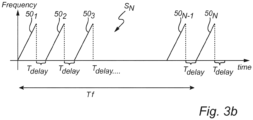
- the electromagnetic transmit signal S T may comprise a plurality of identical frequency sweeps 50.
- the electromagnetic transmit signal may for example be sawtooth-shaped (up-chirp).
- Each frequency sweep 50 may for example have a length of 8 ms and a bandwidth at 3 GHz.
- the frequency sweeps 50 occur immediately after each other.
- the delay T delay may for example be 1 s.
- the delay T delay may improve the resolution, so that the radar level gauge 10 can resolve echoes that are closely spaced in level rate, the because the delay T delay extends the total time T f that the radar level gauge 10 looks at the surface 12 and element 46.
- the processing circuitry 22 may perform a first Fast Fourier Transform FFT 1 on the mixer output signal for each frequency sweep 50 of the plurality of frequency sweeps 50 of the electromagnetic transmit signal S T . Each FFT1 results in a spectrum.
- the processing circuitry 22 stores the resulting consecutive spectra in a distance-time matrix 51, wherein each distance may be a distance bin 52 of e.g. 25 mm.
- the 'distance' here is the distance D, and it could alternatively be called ⁇ range'.
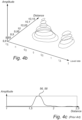
- the processing circuitry 22 performs a second Fast Fourier Transform FFT 2 for each distance (distance bin 52) in the distance-time matrix 51, giving a distance-level rate matrix 54 in which the surface's echo 56 and the aforementioned another echo 58 each is determined in the aforementioned two dimensions (distance and level rate), see also figs. 4a-b .
- the distance-level rate matrix 54 could alternatively be called a two-dimensional spectrum.
- the processing circuitry 22 in applying the range Doppler algorithm resolves the moving surface's echo 56 and disturbance's echo 58.
- both echoes are at the same distance of about 10 meters, but they are nevertheless resolved as two separate echoes 56 and 58.
- the processing circuitry 22 may hence determine the distance D to the surface 12 based on the echo 56.
- Figs. 4a-b show the situation at a specific frequency sweep 50 of the plurality of frequency sweeps 50, and the distance-level rate matrix 54 as shown in figs.
- 4a-b may for example be based on 32 (N in fig. 3b ) preceding frequency sweeps 50. Furthermore in figs. 4a-b , the moving surface's echo 56 has a level rate of 1 mm/sweep, and disturbance's echo 58 has a level rate of -0.3 mm/sweep. For comparison, fig. 4c shows a similar situation but without the range Doppler algorithm, whereby the echoes 56, 58 are not resolved (separated).
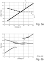
- the surface 12 is moving as the product 14 is being emptied from the tank 16.
- the echoes of the surface 12 at different frequency sweeps as determined by the processing circuitry 22 are plotted and indicated by a solid line 60, and the echoes of the disturbance 46 (stationary) at different frequency sweeps as determined by the processing circuitry 22 are plotted and indicated by a dotted line 62.
- the processing circuitry 22 in applying the range Doppler algorithm resolves the moving surface's echo and the disturbance's echo also while the moving surface 12 passes the disturbance 46.
- the surface's echo may not be resolved, and the determination of the distance to the surface may be lost while the moving surface passes the disturbance, as illustrated in fig. 5b wherein the surface's echoes are indicated by + and the disturbance's echoes are indicated by x.
- Fig. 6 is a flow chart of a method according to an embodiment of the present invention.
- the method may be performed by the radar level gauge 10. That is, the steps of the method may be carried out during operation of the radar level gauge 10.
- the method comprises: transmitting (S1) an electromagnetic transmit signal S T with varying frequency towards the surface 12, receiving (S2) an electromagnetic return signal S R , mixing (S3) the transmitted electromagnetic transmit signal S T with the received electromagnetic return signal S R to provide an output signal including information about the surface's echo 56 and information about another echo 58, applying (S4) an algorithm to the output signal, which algorithm provides the distance-level rate matrix 54 wherein the surface's echo 56 and the another echo 58 each is determined in the two dimensions distance and level rate, and determining (S5) the distance D to the surface 12 based on the thus determined echo 56 of the surface 12.
- Applying the algorithm to the output signal may comprise: performing (S4 1 ) a first Fast Fourier Transform FFT 1 on the output signal for each frequency sweep 50 of the plurality of frequency sweeps 50 of the electromagnetic transmit signal S R ; storing (S4 2 ) the resulting consecutive spectra in a distance-time matrix 51; and performing (S4 3 ) a second Fast Fourier Transform FFT 2 for each distance 52 in the distance-time matrix 51 giving the distance-level rate matrix 54 in which the surface's echo 56 and the another echo 58 each is determined in the two dimensions.
- more than two echoes may be resolved, e.g. the echo of the surface 12, the echo of the disturbance 46, and the echo of the bottom 48.
- one 2D FFT could be performed.
- DFT discrete Fourier transform
- Goertzel algorithm could be used, for example.
- the total time T f may be extended by adding more frequency sweeps to an electromagnetic transmit signal S T where the frequency sweeps occur immediately after each other, for example 64 frequency sweeps instead of 32, and then only perform FFT 1 on some of the frequency sweeps, for example every other frequency sweep.
Landscapes
- Physics & Mathematics (AREA)
- Engineering & Computer Science (AREA)
- Radar, Positioning & Navigation (AREA)
- Remote Sensing (AREA)
- General Physics & Mathematics (AREA)
- Electromagnetism (AREA)
- Computer Networks & Wireless Communication (AREA)
- Fluid Mechanics (AREA)
- Thermal Sciences (AREA)
- Signal Processing (AREA)
- Measurement Of Levels Of Liquids Or Fluent Solid Materials (AREA)
- Radar Systems Or Details Thereof (AREA)
Claims (20)
- Radarfüllstandsanzeiger (10) zum Bestimmen eines Abstands (D) zu einer Oberfläche (12) eines Produkts (14) in einem Tank (16), wobei der Radarfüllstandsanzeiger umfasst:einen Sendeempfänger (18), der eingerichtet ist, um über eine Signalausbreitungsvorrichtung (20) ein elektromagnetisches Sendesignal (ST) mit variierender Frequenz in Richtung der Oberfläche zu senden und um ein elektromagnetisches Rücksignal (SR) zu empfangen;einen Mischer (36), der ausgelegt ist, das gesendete elektromagnetische Sendesignal mit dem empfangenen elektromagnetischen Rücksignal zu mischen, um ein Mischerausgangssignal bereitzustellen, das Informationen über das Echo (56) der Oberfläche und Informationen über ein anderes Echo (58) aufweist;dadurch gekennzeichnet, dass der Radarfüllstandsanzeiger ferner umfasst:
eine Verarbeitungsschaltungsanordnung (22), die eingerichtet ist, um einen Algorithmus auf das Mischerausgangssignal anzuwenden, wobei der Algorithmus eine Abstands-Füllstandraten-Matrix (54) bereitstellt, in der das Echo der Oberfläche und das andere Echo jeweils in den zwei Dimensionen Abstand und Füllstandrate bestimmt werden, und um den Abstand zu der Oberfläche basierend auf dem so bestimmten Echo der Oberfläche zu bestimmen. - Radarfüllstandsanzeiger nach Anspruch 1, wobei sich die Oberfläche bewegt, wobei das andere Echo von einem Element (46; 48) in oder von dem Tank kommt, wobei das Element stationär ist oder sich mit einer unterschiedlichen Füllstandsrate als die sich bewegende Oberfläche bewegt, und wobei die Verarbeitungsschaltungsanordnung bei der Anwendung des Algorithmus eingerichtet ist, um das Echo der sich bewegenden Oberfläche und das Echo des Elements aufzulösen.
- Radarfüllstandsanzeiger nach Anspruch 2, wobei das Element eine Störung (46) in dem Tank ist und wobei die Verarbeitungsschaltungsanordnung bei der Anwendung des Algorithmus eingerichtet ist, um das Echo der sich bewegenden Oberfläche und das Echo der Störung aufzulösen, während die sich bewegende Oberfläche die Störung in dem Tank passiert.
- Radarfüllstandsanzeiger nach Anspruch 2, wobei das Element der Boden (48) des Tanks ist.
- Radarfüllstandsanzeiger nach einem der vorhergehenden Ansprüche 1-4, wobei das elektromagnetische Sendesignal mehrere Frequenzabtastungen (50) umfasst.
- Radarfüllstandsanzeiger nach Anspruch 5, wobei es nach jeder Frequenzabtastung der mehreren Frequenzabtastungen eine Verzögerung (Tdelay) gibt.
- Radarfüllstandsanzeiger nach Anspruch 5 oder 6, wobei die Verarbeitungsschaltungsanordnung eingerichtet ist, um den Algorithmus auf das Mischerausgangssignal anzuwenden durch:Durchführen einer ersten Fast-Fourier-Transformation (FFT1) an dem Mischerausgangssignal für jede von mindestens einigen Frequenzabtastungen der mehreren Frequenzabtastungen des elektromagnetischen Sendesignals;Speichern der resultierenden Spektren in einer Distanz-Zeit-Matrix (51); undDurchführen einer zweiten Fast-Fourier-Transformation (FFT2) für jede Distanz in der Distanz-Zeit-Matrix, die die Distanz-Füllstandsraten-Matrix (54) ergibt, in der das Echo der Oberfläche und das andere Echo jeweils in den zwei Dimensionen bestimmt werden.
- Radarfüllstandsanzeiger nach einem der vorhergehenden Ansprüche 1-7, wobei der Algorithmus ein Bereichs-Doppler-Algorithmus ist.
- Radarfüllstandsanzeiger nach einem der vorhergehenden Ansprüche 1-8, wobei der Radarfüllstandsanzeiger ein frequenzmodulierter Dauerstrichwellen-Radarfüllstandsanzeiger ist.
- System (100), umfassend:einen Tank (16); undeinen Radarfüllstandsanzeiger (10) nach einem der vorhergehenden Ansprüche 1-9.
- Verfahren zum Bestimmen eines Abstands (D) zu einer Oberfläche (12) eines Produkts (14) in einem Tank (16), wobei das Verfahren umfasst:Senden eines elektromagnetischen Sendesignals (ST) mit variierender Frequenz in Richtung der Oberfläche;Empfangen eines elektromagnetischen Rücksignals (SR);Mischen des gesendeten elektromagnetischen Sendesignals mit dem empfangenen elektromagnetischen Rücksignal, um ein Ausgangssignal bereitzustellen, das Informationen über das Echo (56) der Oberfläche und Informationen über ein anderes Echo (58) aufweist;dadurch gekennzeichnet, dass das Verfahren ferner umfasst:Anwenden eines Algorithmus auf das Ausgangssignal, wobei der Algorithmus eine Abstands-Füllstandraten-Matrix (54) bereitstellt, wobei das Echo der Oberfläche und das andere Echo jeweils in den zwei Dimensionen Abstand und Füllstandsrate bestimmt werden; undBestimmen des Abstands zu der Oberfläche basierend auf dem so bestimmten Echo der Oberfläche.
- Verfahren nach Anspruch 11, wobei sich die Oberfläche bewegt, wobei das andere Echo von einem Element (46; 48) in oder von dem Tank kommt, wobei das Element stationär ist oder sich mit einer unterschiedlichen Füllstandsrate als die sich bewegende Oberfläche bewegt, und wobei das Anwenden des Algorithmus ein Auflösen des Echos der sich bewegenden Oberfläche und des Echos des Elements umfasst.
- Verfahren nach Anspruch 12, wobei das Element eine Störung (46) in dem Tank ist und wobei das Anwenden des Algorithmus ein Auflösen des Echos der sich bewegenden Oberfläche und des Echos der Störung, während die sich bewegende Oberfläche die Störung in dem Tank passiert, umfasst.
- Verfahren nach Anspruch 12, wobei das Element der Boden (48) des Tanks ist.
- Verfahren nach einem der vorhergehenden Ansprüche 11-14, wobei das elektromagnetische Sendesignal mehrere Frequenzabtastungen (50) umfasst.
- Verfahren nach Anspruch 15, wobei es nach jeder Frequenzabtastung der mehreren Frequenzabtastungen eine Verzögerung (Tdelay) gibt.
- Verfahren nach Anspruch 15 oder 16, wobei das Anwenden des Algorithmus auf das Ausgangssignal umfasst:Durchführen einer ersten Fast-Fourier-Transformation (FFT1) an dem Ausgangssignal für jeden von mindestens einigen Frequenzabtastungen der mehreren Frequenzabtastungen des elektromagnetischen Sendesignals;Speichern der resultierenden Spektren in einer Distanz-Zeit-Matrix (51); undDurchführen einer zweiten Fast-Fourier-Transformation (FFT2) für jede Distanz in der Distanz-Zeit-Matrix, die die Distanz-Füllstandsraten-Matrix (54) ergibt, in der das Echo der Oberfläche und das andere Echo jeweils in den zwei Dimensionen bestimmt werden.
- Verfahren nach einem der vorhergehenden Ansprüche 11-17, wobei der Algorithmus ein Bereichs-Doppler-Algorithmus ist.
- Computerprogrammprodukt (26), umfassend einen Computerprogrammcode, um, wenn er auf einem Computer ausgeführt wird, die Schritte durchzuführen zum:Anwenden eines Algorithmus auf ein Ausgangssignal, wobei das Ausgangssignal durch Mischen eines elektromagnetischen Sendesignals (ST), das in Richtung einer Oberfläche (12) eines Produkts (14) in einem Tank (16) gesendet wird, mit einem empfangenen elektromagnetischen Rücksignal (SR) bereitgestellt wird, wobei das Ausgangssignal Informationen über das Echo (56) der Oberfläche und Informationen über ein anderes Echo (58) aufweist, wobei der Algorithmus eine Abstand-Füllstandsraten-Matrix (54) bereitstellt, wobei das Echo der Oberfläche und das andere Echo jeweils in den zwei Dimensionen Abstand und Füllstandsrate bestimmt werden; undBestimmen des Abstands zu der Oberfläche basierend auf dem so bestimmten Echo der Oberfläche.
- Elektrisches Signal, das auf einer Trägerwelle verkörpert ist und sich auf einem elektrischen Medium ausbreitet, wobei das elektrische Signal das Computerprogrammprodukt nach Anspruch 19 umfasst.
Applications Claiming Priority (2)
| Application Number | Priority Date | Filing Date | Title |
|---|---|---|---|
| US16/014,509 US10816385B2 (en) | 2018-06-21 | 2018-06-21 | Radar level gauge |
| PCT/EP2019/066319 WO2019243485A1 (en) | 2018-06-21 | 2019-06-20 | Radar level gauge |
Publications (2)
| Publication Number | Publication Date |
|---|---|
| EP3811040A1 EP3811040A1 (de) | 2021-04-28 |
| EP3811040B1 true EP3811040B1 (de) | 2023-07-26 |
Family
ID=67001803
Family Applications (1)
| Application Number | Title | Priority Date | Filing Date |
|---|---|---|---|
| EP19732624.2A Active EP3811040B1 (de) | 2018-06-21 | 2019-06-20 | Radarpegelmessung |
Country Status (4)
| Country | Link |
|---|---|
| US (1) | US10816385B2 (de) |
| EP (1) | EP3811040B1 (de) |
| CN (1) | CN110631656B (de) |
| WO (1) | WO2019243485A1 (de) |
Families Citing this family (4)
| Publication number | Priority date | Publication date | Assignee | Title |
|---|---|---|---|---|
| JP7535876B2 (ja) * | 2020-06-10 | 2024-08-19 | シャープ株式会社 | 収容物検出装置及び収容物検出方法 |
| US12306328B2 (en) * | 2021-04-12 | 2025-05-20 | Texas Instruments Incorporated | Dynamic power management in low power radar solutions |
| EP4160163A1 (de) * | 2021-09-30 | 2023-04-05 | Rosemount Tank Radar AB | Radarfüllstandsmesssystem und verfahren mit verbesserter füllstandsbestimmung |
| CN116500609B (zh) * | 2023-05-16 | 2023-11-21 | 北京锐达仪表有限公司 | 落料状态及物位波动状态检测用复合微波雷达测量系统 |
Citations (2)
| Publication number | Priority date | Publication date | Assignee | Title |
|---|---|---|---|---|
| US20040257269A1 (en) * | 2002-07-19 | 2004-12-23 | Robert Laun | Method and device for determining an expectancy range for a filling level echo and a false echo |
| US20150084806A1 (en) * | 2012-04-19 | 2015-03-26 | S.M.S. Smart Microwave Sensors Gmbh | Method and Device for Determining Distance and Radial Velocity of an Object by Means of Radar Signal |
Family Cites Families (12)
| Publication number | Priority date | Publication date | Assignee | Title |
|---|---|---|---|---|
| US5734347A (en) | 1996-06-10 | 1998-03-31 | Mceligot; E. Lee | Digital holographic radar |
| US5996406A (en) | 1997-05-20 | 1999-12-07 | Motorola, Inc. | Advanced signal process for a material storage measuring device |
| EP0887658B1 (de) | 1997-06-27 | 2004-08-25 | EADS Deutschland GmbH | Füllstandmessradargerät |
| DE19961855B4 (de) * | 1999-12-22 | 2007-11-29 | Endress + Hauser Gmbh + Co. Kg | Verfahren und Vorrichtung zur Bestimmung des Füllstands eines Füllguts in einem Behälter |
| DE10260962A1 (de) * | 2002-12-20 | 2004-07-01 | Endress + Hauser Gmbh + Co. Kg | Füllstandsmeßgerät und Verfahren zur Füllstandsmessung nach dem Laufzeitprinzip |
| RU2244268C2 (ru) * | 2003-03-04 | 2005-01-10 | ООО "Предприятие "Контакт-1" | Способ измерения уровня материала в резервуаре |
| US7729201B2 (en) | 2003-03-25 | 2010-06-01 | Chester Wildey | Method and apparatus for spread spectrum distance and velocity profile measurement |
| EP2527802B1 (de) * | 2011-05-27 | 2019-12-18 | VEGA Grieshaber KG | Vorrichtung und Verfahren zur Ermittlung von Medien- und Behältereigenschaften |
| US9541444B2 (en) * | 2014-04-01 | 2017-01-10 | Rosemount Tank Radar Ab | Self-diagnosing FMCW radar level gauge |
| US10055519B2 (en) * | 2014-10-23 | 2018-08-21 | Honeywell International Inc. | Pulse shape change for interface determination |
| US9541638B2 (en) | 2014-11-11 | 2017-01-10 | Nxp B.V. | MIMO radar system |
| CN206095359U (zh) * | 2016-09-29 | 2017-04-12 | 上海沃纳机电设备有限公司 | 多频率雷达料位计 |
-
2018
- 2018-06-21 US US16/014,509 patent/US10816385B2/en active Active
- 2018-09-29 CN CN201811147971.3A patent/CN110631656B/zh active Active
-
2019
- 2019-06-20 EP EP19732624.2A patent/EP3811040B1/de active Active
- 2019-06-20 WO PCT/EP2019/066319 patent/WO2019243485A1/en not_active Ceased
Patent Citations (2)
| Publication number | Priority date | Publication date | Assignee | Title |
|---|---|---|---|---|
| US20040257269A1 (en) * | 2002-07-19 | 2004-12-23 | Robert Laun | Method and device for determining an expectancy range for a filling level echo and a false echo |
| US20150084806A1 (en) * | 2012-04-19 | 2015-03-26 | S.M.S. Smart Microwave Sensors Gmbh | Method and Device for Determining Distance and Radial Velocity of an Object by Means of Radar Signal |
Also Published As
| Publication number | Publication date |
|---|---|
| WO2019243485A1 (en) | 2019-12-26 |
| CN110631656B (zh) | 2024-12-13 |
| EP3811040A1 (de) | 2021-04-28 |
| CN110631656A (zh) | 2019-12-31 |
| US10816385B2 (en) | 2020-10-27 |
| US20190390997A1 (en) | 2019-12-26 |
Similar Documents
| Publication | Publication Date | Title |
|---|---|---|
| EP4016012B1 (de) | Fmcw-radarfüllstandmessgerät | |
| EP3688420B1 (de) | Adaptive echoschwelle | |
| EP2748566B1 (de) | Radarpegelmessung mit erkennung von bewegten oberflächen | |
| US9024808B2 (en) | Filling level determination using transmit signals with different frequency steps | |
| Vogt et al. | Silo and tank vision: Applica? tions, challenges, and technical solutions for radar measurement of liquids and bulk solids in tanks and silos | |
| US10816385B2 (en) | Radar level gauge | |
| EP3029434B1 (de) | Füllstandsmessung mit radar | |
| CA2640427A1 (en) | Radar liquid level detection using stepped frequency pulses | |
| US9671488B2 (en) | Radar level gauge with signal division | |
| US12607493B2 (en) | Fill-level measurement using a machine learning algorithm | |
| EP2668475B1 (de) | Phasenbasierte verfolgung | |
| US12546642B2 (en) | Angle-resolving fill-level measuring device | |
| CN112689744B (zh) | 料位测量装置 | |
| CN116263497A (zh) | 目标对象的距离确定方法及装置、雷达液位计、智能容器 | |
| EP3959490B1 (de) | Gepulstes radarfüllstandsmessgerät mit verbesserter signalstörungsbeständigkeit | |
| EP3688421B1 (de) | Radarfüllstandsmessung mit wartestatus | |
| US20210172786A1 (en) | Fill level measuring device | |
| EP3405757B1 (de) | Radarpegelmesssystem und verfahren mit signalausbreitungswegmodellierung | |
| US12422298B2 (en) | Radar level gauge system and method with improved filling level determination |
Legal Events
| Date | Code | Title | Description |
|---|---|---|---|
| STAA | Information on the status of an ep patent application or granted ep patent |
Free format text: STATUS: UNKNOWN |
|
| STAA | Information on the status of an ep patent application or granted ep patent |
Free format text: STATUS: THE INTERNATIONAL PUBLICATION HAS BEEN MADE |
|
| PUAI | Public reference made under article 153(3) epc to a published international application that has entered the european phase |
Free format text: ORIGINAL CODE: 0009012 |
|
| STAA | Information on the status of an ep patent application or granted ep patent |
Free format text: STATUS: REQUEST FOR EXAMINATION WAS MADE |
|
| 17P | Request for examination filed |
Effective date: 20201217 |
|
| AK | Designated contracting states |
Kind code of ref document: A1 Designated state(s): AL AT BE BG CH CY CZ DE DK EE ES FI FR GB GR HR HU IE IS IT LI LT LU LV MC MK MT NL NO PL PT RO RS SE SI SK SM TR |
|
| AX | Request for extension of the european patent |
Extension state: BA ME |
|
| RIN1 | Information on inventor provided before grant (corrected) |
Inventor name: BLOMBERG, URBAN Inventor name: DELIN, HAKAN Inventor name: LARSSON, LARS-OVE |
|
| DAV | Request for validation of the european patent (deleted) | ||
| DAX | Request for extension of the european patent (deleted) | ||
| REG | Reference to a national code |
Ref legal event code: R079 Free format text: PREVIOUS MAIN CLASS: G01F0023284000 Ref country code: DE Ref legal event code: R079 Ref document number: 602019033535 Country of ref document: DE Free format text: PREVIOUS MAIN CLASS: G01F0023284000 Ipc: G01F0023800000 |
|
| GRAP | Despatch of communication of intention to grant a patent |
Free format text: ORIGINAL CODE: EPIDOSNIGR1 |
|
| STAA | Information on the status of an ep patent application or granted ep patent |
Free format text: STATUS: GRANT OF PATENT IS INTENDED |
|
| RIC1 | Information provided on ipc code assigned before grant |
Ipc: G01F 23/284 20060101ALI20221017BHEP Ipc: G01S 13/88 20060101ALI20221017BHEP Ipc: G01S 13/536 20060101ALI20221017BHEP Ipc: G01S 13/34 20060101ALI20221017BHEP Ipc: G01S 7/35 20060101ALI20221017BHEP Ipc: G01F 23/80 20220101AFI20221017BHEP |
|
| INTG | Intention to grant announced |
Effective date: 20221115 |
|
| GRAJ | Information related to disapproval of communication of intention to grant by the applicant or resumption of examination proceedings by the epo deleted |
Free format text: ORIGINAL CODE: EPIDOSDIGR1 |
|
| STAA | Information on the status of an ep patent application or granted ep patent |
Free format text: STATUS: REQUEST FOR EXAMINATION WAS MADE |
|
| GRAP | Despatch of communication of intention to grant a patent |
Free format text: ORIGINAL CODE: EPIDOSNIGR1 |
|
| STAA | Information on the status of an ep patent application or granted ep patent |
Free format text: STATUS: GRANT OF PATENT IS INTENDED |
|
| INTC | Intention to grant announced (deleted) | ||
| INTG | Intention to grant announced |
Effective date: 20230217 |
|
| GRAS | Grant fee paid |
Free format text: ORIGINAL CODE: EPIDOSNIGR3 |
|
| GRAA | (expected) grant |
Free format text: ORIGINAL CODE: 0009210 |
|
| STAA | Information on the status of an ep patent application or granted ep patent |
Free format text: STATUS: THE PATENT HAS BEEN GRANTED |
|
| AK | Designated contracting states |
Kind code of ref document: B1 Designated state(s): AL AT BE BG CH CY CZ DE DK EE ES FI FR GB GR HR HU IE IS IT LI LT LU LV MC MK MT NL NO PL PT RO RS SE SI SK SM TR |
|
| REG | Reference to a national code |
Ref country code: CH Ref legal event code: EP |
|
| REG | Reference to a national code |
Ref country code: IE Ref legal event code: FG4D |
|
| REG | Reference to a national code |
Ref country code: DE Ref legal event code: R096 Ref document number: 602019033535 Country of ref document: DE |
|
| REG | Reference to a national code |
Ref country code: LT Ref legal event code: MG9D |
|
| REG | Reference to a national code |
Ref country code: NL Ref legal event code: MP Effective date: 20230726 |
|
| REG | Reference to a national code |
Ref country code: AT Ref legal event code: MK05 Ref document number: 1592419 Country of ref document: AT Kind code of ref document: T Effective date: 20230726 |
|
| PG25 | Lapsed in a contracting state [announced via postgrant information from national office to epo] |
Ref country code: NL Free format text: LAPSE BECAUSE OF FAILURE TO SUBMIT A TRANSLATION OF THE DESCRIPTION OR TO PAY THE FEE WITHIN THE PRESCRIBED TIME-LIMIT Effective date: 20230726 |
|
| PG25 | Lapsed in a contracting state [announced via postgrant information from national office to epo] |
Ref country code: GR Free format text: LAPSE BECAUSE OF FAILURE TO SUBMIT A TRANSLATION OF THE DESCRIPTION OR TO PAY THE FEE WITHIN THE PRESCRIBED TIME-LIMIT Effective date: 20231027 |
|
| PG25 | Lapsed in a contracting state [announced via postgrant information from national office to epo] |
Ref country code: IS Free format text: LAPSE BECAUSE OF FAILURE TO SUBMIT A TRANSLATION OF THE DESCRIPTION OR TO PAY THE FEE WITHIN THE PRESCRIBED TIME-LIMIT Effective date: 20231126 |
|
| PG25 | Lapsed in a contracting state [announced via postgrant information from national office to epo] |
Ref country code: SE Free format text: LAPSE BECAUSE OF FAILURE TO SUBMIT A TRANSLATION OF THE DESCRIPTION OR TO PAY THE FEE WITHIN THE PRESCRIBED TIME-LIMIT Effective date: 20230726 Ref country code: RS Free format text: LAPSE BECAUSE OF FAILURE TO SUBMIT A TRANSLATION OF THE DESCRIPTION OR TO PAY THE FEE WITHIN THE PRESCRIBED TIME-LIMIT Effective date: 20230726 Ref country code: PT Free format text: LAPSE BECAUSE OF FAILURE TO SUBMIT A TRANSLATION OF THE DESCRIPTION OR TO PAY THE FEE WITHIN THE PRESCRIBED TIME-LIMIT Effective date: 20231127 Ref country code: NO Free format text: LAPSE BECAUSE OF FAILURE TO SUBMIT A TRANSLATION OF THE DESCRIPTION OR TO PAY THE FEE WITHIN THE PRESCRIBED TIME-LIMIT Effective date: 20231026 Ref country code: LV Free format text: LAPSE BECAUSE OF FAILURE TO SUBMIT A TRANSLATION OF THE DESCRIPTION OR TO PAY THE FEE WITHIN THE PRESCRIBED TIME-LIMIT Effective date: 20230726 Ref country code: LT Free format text: LAPSE BECAUSE OF FAILURE TO SUBMIT A TRANSLATION OF THE DESCRIPTION OR TO PAY THE FEE WITHIN THE PRESCRIBED TIME-LIMIT Effective date: 20230726 Ref country code: IS Free format text: LAPSE BECAUSE OF FAILURE TO SUBMIT A TRANSLATION OF THE DESCRIPTION OR TO PAY THE FEE WITHIN THE PRESCRIBED TIME-LIMIT Effective date: 20231126 Ref country code: HR Free format text: LAPSE BECAUSE OF FAILURE TO SUBMIT A TRANSLATION OF THE DESCRIPTION OR TO PAY THE FEE WITHIN THE PRESCRIBED TIME-LIMIT Effective date: 20230726 Ref country code: GR Free format text: LAPSE BECAUSE OF FAILURE TO SUBMIT A TRANSLATION OF THE DESCRIPTION OR TO PAY THE FEE WITHIN THE PRESCRIBED TIME-LIMIT Effective date: 20231027 Ref country code: FI Free format text: LAPSE BECAUSE OF FAILURE TO SUBMIT A TRANSLATION OF THE DESCRIPTION OR TO PAY THE FEE WITHIN THE PRESCRIBED TIME-LIMIT Effective date: 20230726 Ref country code: AT Free format text: LAPSE BECAUSE OF FAILURE TO SUBMIT A TRANSLATION OF THE DESCRIPTION OR TO PAY THE FEE WITHIN THE PRESCRIBED TIME-LIMIT Effective date: 20230726 |
|
| PG25 | Lapsed in a contracting state [announced via postgrant information from national office to epo] |
Ref country code: PL Free format text: LAPSE BECAUSE OF FAILURE TO SUBMIT A TRANSLATION OF THE DESCRIPTION OR TO PAY THE FEE WITHIN THE PRESCRIBED TIME-LIMIT Effective date: 20230726 |
|
| PG25 | Lapsed in a contracting state [announced via postgrant information from national office to epo] |
Ref country code: ES Free format text: LAPSE BECAUSE OF FAILURE TO SUBMIT A TRANSLATION OF THE DESCRIPTION OR TO PAY THE FEE WITHIN THE PRESCRIBED TIME-LIMIT Effective date: 20230726 |
|
| REG | Reference to a national code |
Ref country code: DE Ref legal event code: R097 Ref document number: 602019033535 Country of ref document: DE |
|
| PG25 | Lapsed in a contracting state [announced via postgrant information from national office to epo] |
Ref country code: SM Free format text: LAPSE BECAUSE OF FAILURE TO SUBMIT A TRANSLATION OF THE DESCRIPTION OR TO PAY THE FEE WITHIN THE PRESCRIBED TIME-LIMIT Effective date: 20230726 Ref country code: RO Free format text: LAPSE BECAUSE OF FAILURE TO SUBMIT A TRANSLATION OF THE DESCRIPTION OR TO PAY THE FEE WITHIN THE PRESCRIBED TIME-LIMIT Effective date: 20230726 Ref country code: ES Free format text: LAPSE BECAUSE OF FAILURE TO SUBMIT A TRANSLATION OF THE DESCRIPTION OR TO PAY THE FEE WITHIN THE PRESCRIBED TIME-LIMIT Effective date: 20230726 Ref country code: EE Free format text: LAPSE BECAUSE OF FAILURE TO SUBMIT A TRANSLATION OF THE DESCRIPTION OR TO PAY THE FEE WITHIN THE PRESCRIBED TIME-LIMIT Effective date: 20230726 Ref country code: DK Free format text: LAPSE BECAUSE OF FAILURE TO SUBMIT A TRANSLATION OF THE DESCRIPTION OR TO PAY THE FEE WITHIN THE PRESCRIBED TIME-LIMIT Effective date: 20230726 Ref country code: CZ Free format text: LAPSE BECAUSE OF FAILURE TO SUBMIT A TRANSLATION OF THE DESCRIPTION OR TO PAY THE FEE WITHIN THE PRESCRIBED TIME-LIMIT Effective date: 20230726 Ref country code: SK Free format text: LAPSE BECAUSE OF FAILURE TO SUBMIT A TRANSLATION OF THE DESCRIPTION OR TO PAY THE FEE WITHIN THE PRESCRIBED TIME-LIMIT Effective date: 20230726 |
|
| PG25 | Lapsed in a contracting state [announced via postgrant information from national office to epo] |
Ref country code: IT Free format text: LAPSE BECAUSE OF FAILURE TO SUBMIT A TRANSLATION OF THE DESCRIPTION OR TO PAY THE FEE WITHIN THE PRESCRIBED TIME-LIMIT Effective date: 20230726 |
|
| PLBE | No opposition filed within time limit |
Free format text: ORIGINAL CODE: 0009261 |
|
| STAA | Information on the status of an ep patent application or granted ep patent |
Free format text: STATUS: NO OPPOSITION FILED WITHIN TIME LIMIT |
|
| 26N | No opposition filed |
Effective date: 20240429 |
|
| PG25 | Lapsed in a contracting state [announced via postgrant information from national office to epo] |
Ref country code: SI Free format text: LAPSE BECAUSE OF FAILURE TO SUBMIT A TRANSLATION OF THE DESCRIPTION OR TO PAY THE FEE WITHIN THE PRESCRIBED TIME-LIMIT Effective date: 20230726 |
|
| PGFP | Annual fee paid to national office [announced via postgrant information from national office to epo] |
Ref country code: CH Payment date: 20240701 Year of fee payment: 6 |
|
| PG25 | Lapsed in a contracting state [announced via postgrant information from national office to epo] |
Ref country code: BG Free format text: LAPSE BECAUSE OF FAILURE TO SUBMIT A TRANSLATION OF THE DESCRIPTION OR TO PAY THE FEE WITHIN THE PRESCRIBED TIME-LIMIT Effective date: 20230726 |
|
| PG25 | Lapsed in a contracting state [announced via postgrant information from national office to epo] |
Ref country code: BG Free format text: LAPSE BECAUSE OF FAILURE TO SUBMIT A TRANSLATION OF THE DESCRIPTION OR TO PAY THE FEE WITHIN THE PRESCRIBED TIME-LIMIT Effective date: 20230726 |
|
| PG25 | Lapsed in a contracting state [announced via postgrant information from national office to epo] |
Ref country code: MC Free format text: LAPSE BECAUSE OF FAILURE TO SUBMIT A TRANSLATION OF THE DESCRIPTION OR TO PAY THE FEE WITHIN THE PRESCRIBED TIME-LIMIT Effective date: 20230726 |
|
| PG25 | Lapsed in a contracting state [announced via postgrant information from national office to epo] |
Ref country code: LU Free format text: LAPSE BECAUSE OF NON-PAYMENT OF DUE FEES Effective date: 20240620 |
|
| GBPC | Gb: european patent ceased through non-payment of renewal fee |
Effective date: 20240620 |
|
| PG25 | Lapsed in a contracting state [announced via postgrant information from national office to epo] |
Ref country code: IE Free format text: LAPSE BECAUSE OF NON-PAYMENT OF DUE FEES Effective date: 20240620 |
|
| PG25 | Lapsed in a contracting state [announced via postgrant information from national office to epo] |
Ref country code: BE Free format text: LAPSE BECAUSE OF NON-PAYMENT OF DUE FEES Effective date: 20240630 |
|
| PG25 | Lapsed in a contracting state [announced via postgrant information from national office to epo] |
Ref country code: FR Free format text: LAPSE BECAUSE OF NON-PAYMENT OF DUE FEES Effective date: 20240630 |
|
| PG25 | Lapsed in a contracting state [announced via postgrant information from national office to epo] |
Ref country code: GB Free format text: LAPSE BECAUSE OF NON-PAYMENT OF DUE FEES Effective date: 20240620 |
|
| REG | Reference to a national code |
Ref country code: BE Ref legal event code: MM Effective date: 20240630 |
|
| PGFP | Annual fee paid to national office [announced via postgrant information from national office to epo] |
Ref country code: DE Payment date: 20250520 Year of fee payment: 7 |
|
| PG25 | Lapsed in a contracting state [announced via postgrant information from national office to epo] |
Ref country code: CY Free format text: LAPSE BECAUSE OF FAILURE TO SUBMIT A TRANSLATION OF THE DESCRIPTION OR TO PAY THE FEE WITHIN THE PRESCRIBED TIME-LIMIT; INVALID AB INITIO Effective date: 20190620 |
|
| REG | Reference to a national code |
Ref country code: CH Ref legal event code: H13 Free format text: ST27 STATUS EVENT CODE: U-0-0-H10-H13 (AS PROVIDED BY THE NATIONAL OFFICE) Effective date: 20260127 |
|
| PG25 | Lapsed in a contracting state [announced via postgrant information from national office to epo] |
Ref country code: HU Free format text: LAPSE BECAUSE OF FAILURE TO SUBMIT A TRANSLATION OF THE DESCRIPTION OR TO PAY THE FEE WITHIN THE PRESCRIBED TIME-LIMIT; INVALID AB INITIO Effective date: 20190620 |
|
| PG25 | Lapsed in a contracting state [announced via postgrant information from national office to epo] |
Ref country code: CH Free format text: LAPSE BECAUSE OF NON-PAYMENT OF DUE FEES Effective date: 20250630 |