EP4160163A1 - Radarfüllstandsmesssystem und verfahren mit verbesserter füllstandsbestimmung - Google Patents
Radarfüllstandsmesssystem und verfahren mit verbesserter füllstandsbestimmung Download PDFInfo
- Publication number
- EP4160163A1 EP4160163A1 EP21200244.8A EP21200244A EP4160163A1 EP 4160163 A1 EP4160163 A1 EP 4160163A1 EP 21200244 A EP21200244 A EP 21200244A EP 4160163 A1 EP4160163 A1 EP 4160163A1
- Authority
- EP
- European Patent Office
- Prior art keywords
- surface echo
- candidate
- measure
- distance
- signal
- Prior art date
- Legal status (The legal status is an assumption and is not a legal conclusion. Google has not performed a legal analysis and makes no representation as to the accuracy of the status listed.)
- Pending
Links
Images




Classifications
-
- G—PHYSICS
- G01—MEASURING; TESTING
- G01S—RADIO DIRECTION-FINDING; RADIO NAVIGATION; DETERMINING DISTANCE OR VELOCITY BY USE OF RADIO WAVES; LOCATING OR PRESENCE-DETECTING BY USE OF THE REFLECTION OR RERADIATION OF RADIO WAVES; ANALOGOUS ARRANGEMENTS USING OTHER WAVES
- G01S7/00—Details of systems according to groups G01S13/00, G01S15/00, G01S17/00
- G01S7/02—Details of systems according to groups G01S13/00, G01S15/00, G01S17/00 of systems according to group G01S13/00
- G01S7/35—Details of non-pulse systems
- G01S7/352—Receivers
- G01S7/356—Receivers involving particularities of FFT processing
-
- G—PHYSICS
- G01—MEASURING; TESTING
- G01F—MEASURING VOLUME, VOLUME FLOW, MASS FLOW OR LIQUID LEVEL; METERING BY VOLUME
- G01F23/00—Indicating or measuring liquid level or level of fluent solid material, e.g. indicating in terms of volume or indicating by means of an alarm
- G01F23/80—Arrangements for signal processing
- G01F23/802—Particular electronic circuits for digital processing equipment
-
- G—PHYSICS
- G01—MEASURING; TESTING
- G01F—MEASURING VOLUME, VOLUME FLOW, MASS FLOW OR LIQUID LEVEL; METERING BY VOLUME
- G01F23/00—Indicating or measuring liquid level or level of fluent solid material, e.g. indicating in terms of volume or indicating by means of an alarm
- G01F23/22—Indicating or measuring liquid level or level of fluent solid material, e.g. indicating in terms of volume or indicating by means of an alarm by measuring physical variables, other than linear dimensions, pressure or weight, dependent on the level to be measured, e.g. by difference of heat transfer of steam or water
- G01F23/28—Indicating or measuring liquid level or level of fluent solid material, e.g. indicating in terms of volume or indicating by means of an alarm by measuring physical variables, other than linear dimensions, pressure or weight, dependent on the level to be measured, e.g. by difference of heat transfer of steam or water by measuring the variations of parameters of electromagnetic or acoustic waves applied directly to the liquid or fluent solid material
- G01F23/284—Electromagnetic waves
-
- G—PHYSICS
- G01—MEASURING; TESTING
- G01S—RADIO DIRECTION-FINDING; RADIO NAVIGATION; DETERMINING DISTANCE OR VELOCITY BY USE OF RADIO WAVES; LOCATING OR PRESENCE-DETECTING BY USE OF THE REFLECTION OR RERADIATION OF RADIO WAVES; ANALOGOUS ARRANGEMENTS USING OTHER WAVES
- G01S13/00—Systems using the reflection or reradiation of radio waves, e.g. radar systems; Analogous systems using reflection or reradiation of waves whose nature or wavelength is irrelevant or unspecified
- G01S13/02—Systems using reflection of radio waves, e.g. primary radar systems; Analogous systems
- G01S13/50—Systems of measurement based on relative movement of target
- G01S13/58—Velocity or trajectory determination systems; Sense-of-movement determination systems
- G01S13/583—Velocity or trajectory determination systems; Sense-of-movement determination systems using transmission of continuous unmodulated waves, amplitude-, frequency-, or phase-modulated waves and based upon the Doppler effect resulting from movement of targets
- G01S13/584—Velocity or trajectory determination systems; Sense-of-movement determination systems using transmission of continuous unmodulated waves, amplitude-, frequency-, or phase-modulated waves and based upon the Doppler effect resulting from movement of targets adapted for simultaneous range and velocity measurements
-
- G—PHYSICS
- G01—MEASURING; TESTING
- G01S—RADIO DIRECTION-FINDING; RADIO NAVIGATION; DETERMINING DISTANCE OR VELOCITY BY USE OF RADIO WAVES; LOCATING OR PRESENCE-DETECTING BY USE OF THE REFLECTION OR RERADIATION OF RADIO WAVES; ANALOGOUS ARRANGEMENTS USING OTHER WAVES
- G01S13/00—Systems using the reflection or reradiation of radio waves, e.g. radar systems; Analogous systems using reflection or reradiation of waves whose nature or wavelength is irrelevant or unspecified
- G01S13/02—Systems using reflection of radio waves, e.g. primary radar systems; Analogous systems
- G01S13/50—Systems of measurement based on relative movement of target
- G01S13/58—Velocity or trajectory determination systems; Sense-of-movement determination systems
- G01S13/588—Velocity or trajectory determination systems; Sense-of-movement determination systems deriving the velocity value from the range measurement
-
- G—PHYSICS
- G01—MEASURING; TESTING
- G01S—RADIO DIRECTION-FINDING; RADIO NAVIGATION; DETERMINING DISTANCE OR VELOCITY BY USE OF RADIO WAVES; LOCATING OR PRESENCE-DETECTING BY USE OF THE REFLECTION OR RERADIATION OF RADIO WAVES; ANALOGOUS ARRANGEMENTS USING OTHER WAVES
- G01S13/00—Systems using the reflection or reradiation of radio waves, e.g. radar systems; Analogous systems using reflection or reradiation of waves whose nature or wavelength is irrelevant or unspecified
- G01S13/88—Radar or analogous systems specially adapted for specific applications
Definitions
- the present invention relates to a radar level gauge system and method, for determining a filling level of a product in a tank.
- Non-contact filling level determination technologies are advantageously used for determining the filling level of product in tanks in various applications.
- non-contact radar level gauges are very well suited for use in various process tanks with agitators used for blending fluids or solids etc.
- an electromagnetic transmit signal is radiated towards the product in the tank, and it is received a reflection signal resulting from reflection of the transmit signal at the surface and any other reflecting object in the tank.
- the reflection signal may thus, for example, include contributions from reflection of the transmit signal at beams, ladders, holders, agitators, heaters etc. Additionally, the reflection signal may include contributions resulting from multiple reflections between the any reflecting object in the tank and the antenna.
- Each contribution to the reflection signal may be referred to as a surface echo candidate, and to be able to determine the filling level, one of the surface echo candidates needs to be assigned as most likely to correspond to (a single) reflection of the transmit signal at the surface of the product.
- Various possible criteria for this assignment exist, and include, for example, one or several of amplitude, polarity and level rate-of-change of the surface echo candidates.
- a general object of the present invention is to provide for improved filling level determination, and in particular to provide for further improved reliability of the assignment of one of the surface echo candidates as most likely to correspond to reflection of the transmit signal at the surface of the product in a non-contacting radar level gauge system.
- a method of determining a filling level of a product in a tank using a radar level gauge system comprising a transceiver, an antenna, and processing circuitry, the method comprising the steps of: generating and transmitting, by the transceiver, an electromagnetic transmit signal; radiating, by the antenna, the transmit signal towards the product in the tank; returning, by the antenna, an electromagnetic reflection signal resulting from reflection of the transmit signal back towards the transceiver; determining, by the processing circuitry, based on the transmit signal and the reflection signal, for each surface echo candidate in a set of surface echo candidates, a first measure for the surface echo candidate indicative of a distance between the antenna and a surface candidate corresponding to the surface echo candidate and a second measure for the surface echo candidate indicating a rate-of-change distribution of the distance between the antenna and the surface candidate corresponding to the surface echo candidate; assigning one surface echo candidate in the set of surface echo candidates as most likely to correspond to single reflection of the transmit signal at the
- surface echo candidate should be understood a representation that indicates reflection of the transmit signal at an object that may or may not be the surface of the product in the tank.
- the transmit signal may be reflected from one or more fixed objects in the tank, which will result in one or more surface echo candidates that should not be assigned as most likely to correspond to a single reflection of the transmit signal at the surface of the product.
- the first measure indicative of the distance between the antenna and a surface candidate may be any measure from which the distance can be deduced.
- the first measure may be indicative of a travel time for the transmit signal from the transceiver, to the surface candidate, and back to the transceiver.
- the assigning of one surface echo candidate in the set of surface echo candidates as most likely to correspond to a single reflection of the transmit signal at the surface of the product may additionally be based on an evaluation of additional measures, as is per se known to the person skilled in the relevant art.
- the present invention is based on the realization that evaluation, for each surface echo candidate, of the second measure indicating a rate-of-change distribution of the distance between the antenna and the surface candidate corresponding to that surface echo candidate, may provide important input for a more reliable identification of the surface echo candidate that corresponds to a single reflection of the transmit signal at the surface of the product.
- the rate-of-change distribution of the distance between the antenna and a surface candidate provides information about the speed distribution within the area radiated by the antenna for that surface candidate.
- a fixed structure will exhibit a very narrow speed distribution.
- a surface of a disturbed liquid will, however, exhibit a rather broad speed distribution, because it will typically at every instant have surface portions, within the area of the surface that is "visible" to the antenna, that are moving towards the antenna and other surface portions that are moving away from the antenna.
- the reflected energy captured by the antenna from reflection of the transmit signal at the surface of a disturbed liquid product is typically considerably lower, such as ten times lower, than from reflection at the surface of an undisturbed liquid product. This effect makes it more difficult to correctly identify the surface of the product using known methods.
- the liquid product in the tank may, for example, be disturbed by usercontrolled actions, such as stirring or filling or emptying of the tank.
- the method according to embodiments of the present invention may advantageously be carried out at times when it is known that the liquid product in the tank is being disturbed.
- the identification of the surface echo candidate most likely to correspond to single reflection of the transmit signal at the surface of the product achieved at such times will facilitate correct and reliable identification of that surface echo candidate also at subsequent times when the liquid product is not disturbed.
- a radar level gauge system for determining a filling level of a product in a tank
- the radar level gauge system comprising: a transceiver for generating, transmitting, and receiving electromagnetic signals; an antenna coupled to the transceiver and configured to radiate an electromagnetic transmit signal from the transceiver towards the product in the tank, and return an electromagnetic reflection signal resulting from reflection of the transmit signal back towards the transceiver; and processing circuitry coupled to the transceiver for determining the filling level based on a timing relation between the reflection signal and the transmit signal, the processing circuitry being configured to: determine, based on the transmit signal and the reflection signal, for each surface echo candidate in a set of surface echo candidates, a first measure for the surface echo candidate indicative of a distance between the antenna and a surface candidate corresponding to the surface echo candidate and a second measure for the surface echo candidate indicating a rate-of-change distribution of the distance between the antenna and the surface candidate corresponding to the surface echo candidate; assign one
- the “transceiver” may be one functional unit capable of transmitting and receiving microwave signals, or may be a system comprising separate transmitter and receiver units.
- the processing circuitry may be provided as one device or several devices working together.
- the present invention thus relates to a method of determining a filling level of a product in a tank using a radar level gauge system comprising a transceiver, an antenna, and processing circuitry, the method comprising the steps of: generating and transmitting a transmit signal; receiving a reflection signal resulting from reflection of the transmit signal; determining based on the transmit signal and the reflection signal, for each surface echo candidate, a first measure indicative of a distance and a second measure indicating a rate-of-change distribution of the distance; assigning one surface echo candidate as most likely to correspond to single reflection of the transmit signal at the surface of the product, based on an evaluation of the second measure for each surface echo candidate; and determining the filling level based on the first measure for the assigned surface echo candidate.
- Fig 1A schematically shows an exemplary tank arrangement 1 comprising a radar level gauge system 3 according to an example embodiment of the present invention, and a tank 5, such as a reactor vessel.
- the radar level gauge system 3 is installed to measure the filling level of a product 7, in this case a liquid product, in the tank 5.
- the radar level gauge system 3 comprises a measuring electronics unit 9 arranged outside the tank 5, and a radiating antenna 11, here in the form of a horn antenna, arranged inside the tank 5.
- the tank 5 is provided with various auxiliary equipment, in this case including a heater 15 and a stirrer 17 for inducing motion in the product 7.
- the stirrer 17 is operated by a driving arrangement 19 arranged at the top of the tank 5, and the axle 21 of the stirrer 17 is supported by struts 23 inside the tank 5.
- the measurement electronics unit 9 can determine the distance between a reference position (such as a feed-through between the outside and the inside of the tank 5) and the surface 13 of the product 7, whereby the filling level L can be deduced.
- the transmit signal S T is not only reflected by the surface 13 of the product 7, but also by, for example, the struts 23 supporting the axle 21 of the stirrer 17, and other microwave reflecting objects that may be present in the tank 5.
- the reflection signal S R may contain signal components indicative of several reflections, and the analysis of the timing relation between the transmit signal S T and the reflection signal S R may result in a plurality of surface echo candidates.
- the measurement electronics unit 9 comprises a transceiver 25, processing circuitry 27, a communication interface 29, and a communication antenna 31 for wireless communication with, for example, a remote control room (not shown in figs 1A-B ).
- the transceiver 25, the processing circuitry 27, and the communication interface 29 are all illustrated as being enclosed in a measurement electronics unit housing 33.
- the transceiver 25 is configured to generate, transmit and receive electromagnetic signals, and is coupled to the antenna 11 via a feed-through 35 through a wall of the tank 5.
- a feed-through 35 through a wall of the tank 5.
- Various suitable feed-through configurations are, per se, known in the art, and the feed-through 35 is schematically indicated as a simple box in fig 1B .
- the processing circuitry 27 is coupled to the transceiver 25 and is configured to determine the filling level L based on a timing relation between the reflection signal S R and the transmit signal S T as will be described in greater detail further below.
- the communication interface 29 is connected to the processing circuitry 27 and configured to allow external communication via the communication antenna 31.
- the external communication of the radar level gauge system 3 is indicated as being wireless communication.
- communication may, for example, take place over an analog and/or digital wire-based communication channel.
- the communication channel may be a two-wire 4-20 mA loop and the filling level may be communicated by providing a certain current corresponding to the filling level on the two-wire 4-20 mA loop. Digital data may also be sent across such a 4-20 mA loop, using the HART protocol.
- the radar level gauge system 3 may be connectable to an external power source, or may be powered through communication lines.
- the transceiver 25 may include a microwave source 37 for generating the electromagnetic transmit signal S T .
- the microwave source 37 may be controlled by a timer or timing circuitry (not shown) of the processing circuitry 27.
- the microwave source 37 may be connected to the antenna 11 via a power divider 39, and also to a mixer 41.
- the power divider 39 is arranged to connect the electromagnetic reflection signal S R from the antenna 11 to the mixer 41, in order to allow the mixer 41 to mix the electromagnetic transmit signal S T from the microwave source 37 with the electromagnetic reflection signal S R and provide a mixer output signal indicative of a difference between the transmit signal S T and the reflection signal S R .
- the mixer 41 may further optionally be connected to a band pass filter 43 and to an amplifier 45.
- the mixer output signal is provided to the processing circuitry 27, where the mixer output signal is sampled, and processed to form a measurement signal, which is used for further processing by the processing circuitry 27.
- transceiver 25 may typically be implemented in hardware, and may form part of an integrated unit normally referred to as a microwave unit, at least some portions of the processing circuitry 27 may typically be embodied by software modules executed by an embedded processor.
- the invention is not restricted to this particular realization, and any implementation found suitable to realize the herein described functionality may be contemplated.
- an electromagnetic transmit signal S T is generated.
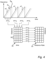
- the transmit signal S T may advantageously comprise a plurality of identical frequency sweeps 47.
- the electromagnetic transmit signal may for example be sawtooth-shaped (up-chirp).
- the frequency sweeps 47 occur immediately after each other. Alternatively, there may be a delay after each frequency sweep 47.
- the transmit signal S T is radiated by the antenna 11 toward the product 7 in the tank 5.
- An electromagnetic reflection signal S R resulting from reflection of the transmit signal S T at the surface 13 of the product 5 is returned by the antenna 11 to the transceiver 25 in step 102.
- the transmit signal ST may additionally be reflected at other reflecting objects in the tank 5, such as the heater 15 and/or the support strut 23. Each such reflection can be represented by a surface echo candidate.
- the surface echo candidates can be obtained as follows. Referring to fig 2 , the reflection signal S R is passed, via the power divider 39, to the mixer 41. In the mixer 41, the reflection signal S R is mixed with the transmit signal S T . As is, per se, well-known, the output from the mixer 41 - the mixer output - is indicative of a difference between the signals input to the mixer 41. In this case, the mixer output is thus indicative of the difference between the reflection signal S R and the transmit signal S T . In the processing circuitry the mixer output may be sampled, to form a digital measurement signal S m . The measurement signal S m contains information about each surface echo candidate.
- the processing circuitry 27 determines a first measure and a second measure for each surface echo candidate based on the transmit signal S T and the reflection signal S R .
- the first measure is indicative of a distance between the antenna 11 and a surface candidate corresponding to the surface echo candidate.
- the second measure is indicative of a rate-of-change distribution of the distance between the antenna 11 and the surface candidate corresponding to the surface echo candidate.
- the first measure and the second measure for each surface echo candidate may be determined based on the above-mentioned measurement signal S m .
- the determination of the first measure and the second measure may involve determining a distance-distance rate matrix based on the measurement signal S m .
- the processing circuitry 27 may perform a two-dimensional digital Fourier transformation on the measurement signal S m .
- the processing circuitry 27 may perform a first Fast Fourier Transform FFT1 on the measurement signal S m for each frequency sweep 47 of the plurality of frequency sweeps 47 of the electromagnetic transmit signal ST. Each FFT1 results in a spectrum.
- the processing circuitry 27 stores the resulting consecutive spectra in a distance-time matrix 49, wherein each distance D may be a distance bin 51. Thereafter, the processing circuitry 27 may perform a second Fast Fourier Transform FFT2 for each distance (distance bin 51) in the distance-time matrix 49, resulting in a distance-distance rate matrix 53.
- This procedure is, per se, well known, and is sometimes referred to as Range-Doppler processing.
- the distance-distance rate matrix 53 may be referred to as a Range-Doppler matrix.
- the first measure indicative of the distance between the antenna 11 and the surface candidate corresponding to the surface echo candidate may thus be determined based on the distance-distance rate matrix 53.
- the first measure may be determined directly from the distance-time matrix 49.
- the second measure indicative of the rate-of-change distribution of the distance between the antenna 11 and the surface candidate corresponding to the surface echo candidate may be determined based on the distance-distance rate matrix 53.
- the diagrams in figs 5A-B show the signal amplitude values in the distance bin, in the distance-distance rate matrix 53, of the surface echo candidate corresponding to the surface 13 of the product 7.
- the amplitudes have been sorted from lowest to highest, to form the curve 55.
- a subset 57 is centered around the median amplitude and includes a predetermined number of amplitude values.
- the second measure for the surface echo candidate can then be determined as the average value of the amplitude values in the subset 57 divided by the maximum amplitude value 59.
- Fig 5A illustrates a situation where the stirrer 17 in the tank 5 in fig 1A is activated, and the liquid product 7 in the tank 5 is disturbed. There is a substantial signal amplitude value for many different rates-of-change of the distance between the antenna 11 and the surface 13 of the product 7. As can be understood by studying the curve 55 in fig 5A , this will result in a relatively high value of the second measure for the surface echo candidate corresponding to the surface 13 of the product 7.
- Fig 5B illustrates a situation where the stirrer 17 in the tank 5 in fig 1A is deactivated, and the liquid product 7 in the tank 5 is not disturbed. There will therefore be a strong peak for a zero rate-of-change of the distance between the antenna 11 and the surface 13 of the product 7. As can be understood by studying the curve 55 in fig 5B , this will result in a relatively low value of the second measure for the surface echo candidate corresponding to the surface 13 of the product 7.
- any statistical measure indicating a width of a distribution may be used, such as variance or standard deviation, etc.
- one surface echo candidate in the set of surface echo candidates is assigned as most likely to correspond to a single reflection of the transmit signal S T at the surface 13 of the product 7 in the tank 5, based on an evaluation of the second measure for each surface echo candidate in the set of surface echo candidates.
- Fig 6A is a diagram schematically illustrating an exemplary development over time of the distance between the antenna 11 and the surface 13 of the product 7 in the tank 5 in fig 1A , for a tank filling event during which the stirrer 17 is sometimes deactivated and sometimes activated.
- the tank filling event starts at a relatively long distance, that is, a relatively low filling level. Filling of product then takes place at filling time periods that are characterized by a decreasing distance. The filling time periods are separated by idle time periods that are characterized by a constant distance.
- the stirrer 17 is inactive during time periods indicated by the solid line segments 63a-c in fig 6A , and the stirrer is active during time periods indicated by the dashed line segments 65a-b.
- the point in time where the filling level determination is carried out is indicated by the letter 'x' on the second dashed line segment 65b. Accordingly, the filling level determination is carried out while the stirrer 17 is activated.
- Fig 6B is a diagram schematically showing the distance from the antenna and the rate-of-change distribution of the distance from the antenna for three exemplary surface echo candidates.
- a first surface echo candidate corresponds to reflection of the transmit signal S T at a first surface candidate at a first distance D 1
- a second surface echo candidate corresponds to reflection of the transmit signal S T at a second surface candidate at a second distance D 2
- a third surface echo candidate corresponds to reflection of the transmit signal S T at a third surface candidate at a third distance D 3 .
- the first surface candidate is the strut 23 supporting the axle 21 of the stirrer 17
- the second surface candidate is the surface 13 of the product 7
- the third surface candidate is also the surface 13 of the product, but following reflection at the antenna 11, and a second reflection at the surface 13 of the product 7, a so-called double reflection.
- the second measure of each of the surface echo candidates may be compared with a predefined threshold measure indicating a threshold width of the rate-of-change distribution of the distance.
- the second measure may, for example, be determined in accordance with the procedure described above with reference to figs 5A-B , and the predefined threshold measure may be selected to distinguish between a case when the liquid product 7 is disturbed - for example by the stirrer 17 being activated - and a case when the liquid product 7 is not disturbed.
- the stirrer 17 is activated and the liquid product 7 is thus disturbed.
- the second measure of the second surface echo candidate (at the second distance D 2 ) and the second measure of the third surface echo candidate (at the third distance D 3 ) will indicate a width of the rate-of-change distribution being greater than the threshold width indicated by the predefined threshold measure.
- the first surface echo candidate results from reflection of the transmit signal S T at a stationary object (the strut 23)
- the second measure of the first surface echo candidate (at the first distance D 1 ) will not indicate a width of the rate-of-change distribution being greater than the threshold width indicated by the predefined threshold measure.
- the second echo candidate may be assigned as most likely to correspond to single reflection at the surface 13 because it is the disturbed surface closest to the antenna 11.
- the second distance D 2 and the third distance D 3 may be compared, and if it can be determined that the third distance D 3 is an integer multiple of the second distance D 2 , the third surface echo candidate can be identified as resulting from a double (or triple) reflection, and the assignment of the second surface echo candidate as most likely to correspond to single reflection at the surface 13 can be considered to be more reliable.
- embodiments of the method according to the present invention may mainly be used when it can be determined that the liquid product 7 in the tank 5 is disturbed.
- the method may include the step of inducing a disturbance, such as by operating the stirrer 17 while the method is being carried out.
- identification of the surface echo candidate resulting from single reflection at the surface 13 of the product 7 may simplify tracking of this surface echo candidate also at times when there is no disturbance of the product 7.
- the filling level L is determined based on the first measure for the surface echo candidate assigned as most likely to correspond to reflection of the transmit signal at the surface of the product.
- the antenna need not be a horn antenna as indicated in the drawings, but various other types of radiating antennas may be used. Examples of such types radiating antennas are horn antennas, parabolic antennas, rod antennas, patch antennas etc.
Landscapes
- Physics & Mathematics (AREA)
- Engineering & Computer Science (AREA)
- Radar, Positioning & Navigation (AREA)
- Remote Sensing (AREA)
- General Physics & Mathematics (AREA)
- Electromagnetism (AREA)
- Fluid Mechanics (AREA)
- Computer Networks & Wireless Communication (AREA)
- Signal Processing (AREA)
- Thermal Sciences (AREA)
- Measurement Of Levels Of Liquids Or Fluent Solid Materials (AREA)
Priority Applications (3)
| Application Number | Priority Date | Filing Date | Title |
|---|---|---|---|
| EP21200244.8A EP4160163A1 (de) | 2021-09-30 | 2021-09-30 | Radarfüllstandsmesssystem und verfahren mit verbesserter füllstandsbestimmung |
| US17/947,460 US12422298B2 (en) | 2021-09-30 | 2022-09-19 | Radar level gauge system and method with improved filling level determination |
| CN202211178504.3A CN115902799A (zh) | 2021-09-30 | 2022-09-26 | 确定罐中的产品的填充物位的方法和雷达物位计系统 |
Applications Claiming Priority (1)
| Application Number | Priority Date | Filing Date | Title |
|---|---|---|---|
| EP21200244.8A EP4160163A1 (de) | 2021-09-30 | 2021-09-30 | Radarfüllstandsmesssystem und verfahren mit verbesserter füllstandsbestimmung |
Publications (1)
| Publication Number | Publication Date |
|---|---|
| EP4160163A1 true EP4160163A1 (de) | 2023-04-05 |
Family
ID=78332455
Family Applications (1)
| Application Number | Title | Priority Date | Filing Date |
|---|---|---|---|
| EP21200244.8A Pending EP4160163A1 (de) | 2021-09-30 | 2021-09-30 | Radarfüllstandsmesssystem und verfahren mit verbesserter füllstandsbestimmung |
Country Status (3)
| Country | Link |
|---|---|
| US (1) | US12422298B2 (de) |
| EP (1) | EP4160163A1 (de) |
| CN (1) | CN115902799A (de) |
Citations (4)
| Publication number | Priority date | Publication date | Assignee | Title |
|---|---|---|---|---|
| US20140028492A1 (en) * | 2011-04-14 | 2014-01-30 | Endress + Hauser Gmbh + Co. Kg | Calibration- and/or monitoring method for fmcw radar fill level measuring devices |
| US20150101405A1 (en) * | 2012-06-05 | 2015-04-16 | Endress + Hauser Gmbh + Co. Kg | Method for fill level measurement using the travel time principle |
| US20190390997A1 (en) * | 2018-06-21 | 2019-12-26 | Rosemount Tank Radar Ab | Radar level gauge |
| DE102019216879B3 (de) * | 2019-10-31 | 2021-04-01 | Vega Grieshaber Kg | FMCW-Radarmessgerät |
Family Cites Families (5)
| Publication number | Priority date | Publication date | Assignee | Title |
|---|---|---|---|---|
| SE0403165D0 (sv) * | 2004-12-23 | 2004-12-23 | Saab Rosemount Tank Radar Ab | A radar level gauge system |
| DE102012107146A1 (de) * | 2012-08-03 | 2014-02-20 | Endress + Hauser Gmbh + Co. Kg | Verfahren zur Bestimmung und/oder Überwachung des Füllstands eines Mediums in einem Behälter |
| HUE037717T2 (hu) | 2015-07-02 | 2018-09-28 | Grieshaber Vega Kg | Eljárás töltésszintmérésre és töltésszintmérõ készülék |
| US10775221B2 (en) * | 2017-09-29 | 2020-09-15 | Rosemount Tank Radar Ab | Adaptive echo threshold |
| EP3575817A1 (de) * | 2018-05-30 | 2019-12-04 | VEGA Grieshaber KG | Verfahren zur füllstandmessung |
-
2021
- 2021-09-30 EP EP21200244.8A patent/EP4160163A1/de active Pending
-
2022
- 2022-09-19 US US17/947,460 patent/US12422298B2/en active Active
- 2022-09-26 CN CN202211178504.3A patent/CN115902799A/zh active Pending
Patent Citations (4)
| Publication number | Priority date | Publication date | Assignee | Title |
|---|---|---|---|---|
| US20140028492A1 (en) * | 2011-04-14 | 2014-01-30 | Endress + Hauser Gmbh + Co. Kg | Calibration- and/or monitoring method for fmcw radar fill level measuring devices |
| US20150101405A1 (en) * | 2012-06-05 | 2015-04-16 | Endress + Hauser Gmbh + Co. Kg | Method for fill level measurement using the travel time principle |
| US20190390997A1 (en) * | 2018-06-21 | 2019-12-26 | Rosemount Tank Radar Ab | Radar level gauge |
| DE102019216879B3 (de) * | 2019-10-31 | 2021-04-01 | Vega Grieshaber Kg | FMCW-Radarmessgerät |
Also Published As
| Publication number | Publication date |
|---|---|
| CN115902799A (zh) | 2023-04-04 |
| US12422298B2 (en) | 2025-09-23 |
| US20230095448A1 (en) | 2023-03-30 |
Similar Documents
| Publication | Publication Date | Title |
|---|---|---|
| CN102812337B (zh) | 用于利用传播时间测量方法确认并且监测介质在容器中的填充水平的方法 | |
| US10775221B2 (en) | Adaptive echo threshold | |
| US11927469B2 (en) | Proof test of radar level gauge system | |
| US9671488B2 (en) | Radar level gauge with signal division | |
| EP3811040B1 (de) | Radarpegelmessung | |
| US20240271985A1 (en) | Fill-level measurement using a machine learning algorithm | |
| US8065912B2 (en) | Filling level sensor and method for measuring filling level | |
| US11977179B2 (en) | Leakage detection system and method | |
| US11906344B2 (en) | Method for measuring fill levels | |
| US12422298B2 (en) | Radar level gauge system and method with improved filling level determination | |
| CN113075657B (zh) | 一种散射源高度的测试方法及检测装置 | |
| US11747187B2 (en) | Method for generating a masking curve for a fill state measuring device | |
| US12313439B2 (en) | Radar level gauge system and method with transmission line probe and stepped frequency sweep | |
| EP3688421B1 (de) | Radarfüllstandsmessung mit wartestatus | |
| US12480799B2 (en) | Fill level measuring device | |
| US20240219259A1 (en) | Vibration estimation system and method |
Legal Events
| Date | Code | Title | Description |
|---|---|---|---|
| PUAI | Public reference made under article 153(3) epc to a published international application that has entered the european phase |
Free format text: ORIGINAL CODE: 0009012 |
|
| STAA | Information on the status of an ep patent application or granted ep patent |
Free format text: STATUS: THE APPLICATION HAS BEEN PUBLISHED |
|
| AK | Designated contracting states |
Kind code of ref document: A1 Designated state(s): AL AT BE BG CH CY CZ DE DK EE ES FI FR GB GR HR HU IE IS IT LI LT LU LV MC MK MT NL NO PL PT RO RS SE SI SK SM TR |
|
| STAA | Information on the status of an ep patent application or granted ep patent |
Free format text: STATUS: REQUEST FOR EXAMINATION WAS MADE |
|
| 17P | Request for examination filed |
Effective date: 20231003 |
|
| RBV | Designated contracting states (corrected) |
Designated state(s): AL AT BE BG CH CY CZ DE DK EE ES FI FR GB GR HR HU IE IS IT LI LT LU LV MC MK MT NL NO PL PT RO RS SE SI SK SM TR |
|
| STAA | Information on the status of an ep patent application or granted ep patent |
Free format text: STATUS: EXAMINATION IS IN PROGRESS |
|
| 17Q | First examination report despatched |
Effective date: 20250312 |