EP3812675A1 - Procédé et appareil de séparation d'air par distillation cryogénique - Google Patents
Procédé et appareil de séparation d'air par distillation cryogénique Download PDFInfo
- Publication number
- EP3812675A1 EP3812675A1 EP20203664.6A EP20203664A EP3812675A1 EP 3812675 A1 EP3812675 A1 EP 3812675A1 EP 20203664 A EP20203664 A EP 20203664A EP 3812675 A1 EP3812675 A1 EP 3812675A1
- Authority
- EP
- European Patent Office
- Prior art keywords
- column
- enriched
- liquid
- oxygen
- argon
- Prior art date
- Legal status (The legal status is an assumption and is not a legal conclusion. Google has not performed a legal analysis and makes no representation as to the accuracy of the status listed.)
- Granted
Links
Images



Classifications
-
- F—MECHANICAL ENGINEERING; LIGHTING; HEATING; WEAPONS; BLASTING
- F25—REFRIGERATION OR COOLING; COMBINED HEATING AND REFRIGERATION SYSTEMS; HEAT PUMP SYSTEMS; MANUFACTURE OR STORAGE OF ICE; LIQUEFACTION SOLIDIFICATION OF GASES
- F25J—LIQUEFACTION, SOLIDIFICATION OR SEPARATION OF GASES OR GASEOUS OR LIQUEFIED GASEOUS MIXTURES BY PRESSURE AND COLD TREATMENT OR BY BRINGING THEM INTO THE SUPERCRITICAL STATE
- F25J3/00—Processes or apparatus for separating the constituents of gaseous or liquefied gaseous mixtures involving the use of liquefaction or solidification
- F25J3/02—Processes or apparatus for separating the constituents of gaseous or liquefied gaseous mixtures involving the use of liquefaction or solidification by rectification, i.e. by continuous interchange of heat and material between a vapour stream and a liquid stream
- F25J3/04—Processes or apparatus for separating the constituents of gaseous or liquefied gaseous mixtures involving the use of liquefaction or solidification by rectification, i.e. by continuous interchange of heat and material between a vapour stream and a liquid stream for air
- F25J3/04642—Recovering noble gases from air
- F25J3/04648—Recovering noble gases from air argon
- F25J3/04654—Producing crude argon in a crude argon column
- F25J3/04709—Producing crude argon in a crude argon column as an auxiliary column system in at least a dual pressure main column system
-
- F—MECHANICAL ENGINEERING; LIGHTING; HEATING; WEAPONS; BLASTING
- F25—REFRIGERATION OR COOLING; COMBINED HEATING AND REFRIGERATION SYSTEMS; HEAT PUMP SYSTEMS; MANUFACTURE OR STORAGE OF ICE; LIQUEFACTION SOLIDIFICATION OF GASES
- F25J—LIQUEFACTION, SOLIDIFICATION OR SEPARATION OF GASES OR GASEOUS OR LIQUEFIED GASEOUS MIXTURES BY PRESSURE AND COLD TREATMENT OR BY BRINGING THEM INTO THE SUPERCRITICAL STATE
- F25J3/00—Processes or apparatus for separating the constituents of gaseous or liquefied gaseous mixtures involving the use of liquefaction or solidification
- F25J3/02—Processes or apparatus for separating the constituents of gaseous or liquefied gaseous mixtures involving the use of liquefaction or solidification by rectification, i.e. by continuous interchange of heat and material between a vapour stream and a liquid stream
- F25J3/04—Processes or apparatus for separating the constituents of gaseous or liquefied gaseous mixtures involving the use of liquefaction or solidification by rectification, i.e. by continuous interchange of heat and material between a vapour stream and a liquid stream for air
- F25J3/04248—Generation of cold for compensating heat leaks or liquid production, e.g. by Joule-Thompson expansion
- F25J3/04284—Generation of cold for compensating heat leaks or liquid production, e.g. by Joule-Thompson expansion using internal refrigeration by open-loop gas work expansion, e.g. of intermediate or oxygen enriched (waste-)streams
-
- F—MECHANICAL ENGINEERING; LIGHTING; HEATING; WEAPONS; BLASTING
- F25—REFRIGERATION OR COOLING; COMBINED HEATING AND REFRIGERATION SYSTEMS; HEAT PUMP SYSTEMS; MANUFACTURE OR STORAGE OF ICE; LIQUEFACTION SOLIDIFICATION OF GASES
- F25J—LIQUEFACTION, SOLIDIFICATION OR SEPARATION OF GASES OR GASEOUS OR LIQUEFIED GASEOUS MIXTURES BY PRESSURE AND COLD TREATMENT OR BY BRINGING THEM INTO THE SUPERCRITICAL STATE
- F25J3/00—Processes or apparatus for separating the constituents of gaseous or liquefied gaseous mixtures involving the use of liquefaction or solidification
- F25J3/02—Processes or apparatus for separating the constituents of gaseous or liquefied gaseous mixtures involving the use of liquefaction or solidification by rectification, i.e. by continuous interchange of heat and material between a vapour stream and a liquid stream
- F25J3/04—Processes or apparatus for separating the constituents of gaseous or liquefied gaseous mixtures involving the use of liquefaction or solidification by rectification, i.e. by continuous interchange of heat and material between a vapour stream and a liquid stream for air
- F25J3/04406—Processes or apparatus for separating the constituents of gaseous or liquefied gaseous mixtures involving the use of liquefaction or solidification by rectification, i.e. by continuous interchange of heat and material between a vapour stream and a liquid stream for air using a dual pressure main column system
- F25J3/04412—Processes or apparatus for separating the constituents of gaseous or liquefied gaseous mixtures involving the use of liquefaction or solidification by rectification, i.e. by continuous interchange of heat and material between a vapour stream and a liquid stream for air using a dual pressure main column system in a classical double column flowsheet, i.e. with thermal coupling by a main reboiler-condenser in the bottom of low pressure respectively top of high pressure column
-
- F—MECHANICAL ENGINEERING; LIGHTING; HEATING; WEAPONS; BLASTING
- F25—REFRIGERATION OR COOLING; COMBINED HEATING AND REFRIGERATION SYSTEMS; HEAT PUMP SYSTEMS; MANUFACTURE OR STORAGE OF ICE; LIQUEFACTION SOLIDIFICATION OF GASES
- F25J—LIQUEFACTION, SOLIDIFICATION OR SEPARATION OF GASES OR GASEOUS OR LIQUEFIED GASEOUS MIXTURES BY PRESSURE AND COLD TREATMENT OR BY BRINGING THEM INTO THE SUPERCRITICAL STATE
- F25J3/00—Processes or apparatus for separating the constituents of gaseous or liquefied gaseous mixtures involving the use of liquefaction or solidification
- F25J3/02—Processes or apparatus for separating the constituents of gaseous or liquefied gaseous mixtures involving the use of liquefaction or solidification by rectification, i.e. by continuous interchange of heat and material between a vapour stream and a liquid stream
- F25J3/04—Processes or apparatus for separating the constituents of gaseous or liquefied gaseous mixtures involving the use of liquefaction or solidification by rectification, i.e. by continuous interchange of heat and material between a vapour stream and a liquid stream for air
- F25J3/04436—Processes or apparatus for separating the constituents of gaseous or liquefied gaseous mixtures involving the use of liquefaction or solidification by rectification, i.e. by continuous interchange of heat and material between a vapour stream and a liquid stream for air using at least a triple pressure main column system
- F25J3/04448—Processes or apparatus for separating the constituents of gaseous or liquefied gaseous mixtures involving the use of liquefaction or solidification by rectification, i.e. by continuous interchange of heat and material between a vapour stream and a liquid stream for air using at least a triple pressure main column system in a double column flowsheet with an intermediate pressure column
-
- F—MECHANICAL ENGINEERING; LIGHTING; HEATING; WEAPONS; BLASTING
- F25—REFRIGERATION OR COOLING; COMBINED HEATING AND REFRIGERATION SYSTEMS; HEAT PUMP SYSTEMS; MANUFACTURE OR STORAGE OF ICE; LIQUEFACTION SOLIDIFICATION OF GASES
- F25J—LIQUEFACTION, SOLIDIFICATION OR SEPARATION OF GASES OR GASEOUS OR LIQUEFIED GASEOUS MIXTURES BY PRESSURE AND COLD TREATMENT OR BY BRINGING THEM INTO THE SUPERCRITICAL STATE
- F25J3/00—Processes or apparatus for separating the constituents of gaseous or liquefied gaseous mixtures involving the use of liquefaction or solidification
- F25J3/02—Processes or apparatus for separating the constituents of gaseous or liquefied gaseous mixtures involving the use of liquefaction or solidification by rectification, i.e. by continuous interchange of heat and material between a vapour stream and a liquid stream
- F25J3/04—Processes or apparatus for separating the constituents of gaseous or liquefied gaseous mixtures involving the use of liquefaction or solidification by rectification, i.e. by continuous interchange of heat and material between a vapour stream and a liquid stream for air
- F25J3/0446—Processes or apparatus for separating the constituents of gaseous or liquefied gaseous mixtures involving the use of liquefaction or solidification by rectification, i.e. by continuous interchange of heat and material between a vapour stream and a liquid stream for air using the heat generated by mixing two different phases
-
- F—MECHANICAL ENGINEERING; LIGHTING; HEATING; WEAPONS; BLASTING
- F25—REFRIGERATION OR COOLING; COMBINED HEATING AND REFRIGERATION SYSTEMS; HEAT PUMP SYSTEMS; MANUFACTURE OR STORAGE OF ICE; LIQUEFACTION SOLIDIFICATION OF GASES
- F25J—LIQUEFACTION, SOLIDIFICATION OR SEPARATION OF GASES OR GASEOUS OR LIQUEFIED GASEOUS MIXTURES BY PRESSURE AND COLD TREATMENT OR BY BRINGING THEM INTO THE SUPERCRITICAL STATE
- F25J3/00—Processes or apparatus for separating the constituents of gaseous or liquefied gaseous mixtures involving the use of liquefaction or solidification
- F25J3/02—Processes or apparatus for separating the constituents of gaseous or liquefied gaseous mixtures involving the use of liquefaction or solidification by rectification, i.e. by continuous interchange of heat and material between a vapour stream and a liquid stream
- F25J3/04—Processes or apparatus for separating the constituents of gaseous or liquefied gaseous mixtures involving the use of liquefaction or solidification by rectification, i.e. by continuous interchange of heat and material between a vapour stream and a liquid stream for air
- F25J3/04624—Processes or apparatus for separating the constituents of gaseous or liquefied gaseous mixtures involving the use of liquefaction or solidification by rectification, i.e. by continuous interchange of heat and material between a vapour stream and a liquid stream for air using integrated mass and heat exchange, so-called non-adiabatic rectification, e.g. dephlegmator, reflux exchanger
- F25J3/0463—Simultaneously between rectifying and stripping sections, i.e. double dephlegmator
-
- F—MECHANICAL ENGINEERING; LIGHTING; HEATING; WEAPONS; BLASTING
- F25—REFRIGERATION OR COOLING; COMBINED HEATING AND REFRIGERATION SYSTEMS; HEAT PUMP SYSTEMS; MANUFACTURE OR STORAGE OF ICE; LIQUEFACTION SOLIDIFICATION OF GASES
- F25J—LIQUEFACTION, SOLIDIFICATION OR SEPARATION OF GASES OR GASEOUS OR LIQUEFIED GASEOUS MIXTURES BY PRESSURE AND COLD TREATMENT OR BY BRINGING THEM INTO THE SUPERCRITICAL STATE
- F25J3/00—Processes or apparatus for separating the constituents of gaseous or liquefied gaseous mixtures involving the use of liquefaction or solidification
- F25J3/02—Processes or apparatus for separating the constituents of gaseous or liquefied gaseous mixtures involving the use of liquefaction or solidification by rectification, i.e. by continuous interchange of heat and material between a vapour stream and a liquid stream
- F25J3/04—Processes or apparatus for separating the constituents of gaseous or liquefied gaseous mixtures involving the use of liquefaction or solidification by rectification, i.e. by continuous interchange of heat and material between a vapour stream and a liquid stream for air
- F25J3/04642—Recovering noble gases from air
- F25J3/04648—Recovering noble gases from air argon
-
- F—MECHANICAL ENGINEERING; LIGHTING; HEATING; WEAPONS; BLASTING
- F25—REFRIGERATION OR COOLING; COMBINED HEATING AND REFRIGERATION SYSTEMS; HEAT PUMP SYSTEMS; MANUFACTURE OR STORAGE OF ICE; LIQUEFACTION SOLIDIFICATION OF GASES
- F25J—LIQUEFACTION, SOLIDIFICATION OR SEPARATION OF GASES OR GASEOUS OR LIQUEFIED GASEOUS MIXTURES BY PRESSURE AND COLD TREATMENT OR BY BRINGING THEM INTO THE SUPERCRITICAL STATE
- F25J3/00—Processes or apparatus for separating the constituents of gaseous or liquefied gaseous mixtures involving the use of liquefaction or solidification
- F25J3/02—Processes or apparatus for separating the constituents of gaseous or liquefied gaseous mixtures involving the use of liquefaction or solidification by rectification, i.e. by continuous interchange of heat and material between a vapour stream and a liquid stream
- F25J3/04—Processes or apparatus for separating the constituents of gaseous or liquefied gaseous mixtures involving the use of liquefaction or solidification by rectification, i.e. by continuous interchange of heat and material between a vapour stream and a liquid stream for air
- F25J3/04642—Recovering noble gases from air
- F25J3/04648—Recovering noble gases from air argon
- F25J3/04654—Producing crude argon in a crude argon column
- F25J3/04666—Producing crude argon in a crude argon column as a parallel working rectification column of the low pressure column in a dual pressure main column system
-
- F—MECHANICAL ENGINEERING; LIGHTING; HEATING; WEAPONS; BLASTING
- F25—REFRIGERATION OR COOLING; COMBINED HEATING AND REFRIGERATION SYSTEMS; HEAT PUMP SYSTEMS; MANUFACTURE OR STORAGE OF ICE; LIQUEFACTION SOLIDIFICATION OF GASES
- F25J—LIQUEFACTION, SOLIDIFICATION OR SEPARATION OF GASES OR GASEOUS OR LIQUEFIED GASEOUS MIXTURES BY PRESSURE AND COLD TREATMENT OR BY BRINGING THEM INTO THE SUPERCRITICAL STATE
- F25J3/00—Processes or apparatus for separating the constituents of gaseous or liquefied gaseous mixtures involving the use of liquefaction or solidification
- F25J3/02—Processes or apparatus for separating the constituents of gaseous or liquefied gaseous mixtures involving the use of liquefaction or solidification by rectification, i.e. by continuous interchange of heat and material between a vapour stream and a liquid stream
- F25J3/04—Processes or apparatus for separating the constituents of gaseous or liquefied gaseous mixtures involving the use of liquefaction or solidification by rectification, i.e. by continuous interchange of heat and material between a vapour stream and a liquid stream for air
- F25J3/04642—Recovering noble gases from air
- F25J3/04648—Recovering noble gases from air argon
- F25J3/04654—Producing crude argon in a crude argon column
- F25J3/04666—Producing crude argon in a crude argon column as a parallel working rectification column of the low pressure column in a dual pressure main column system
- F25J3/04672—Producing crude argon in a crude argon column as a parallel working rectification column of the low pressure column in a dual pressure main column system having a top condenser
-
- F—MECHANICAL ENGINEERING; LIGHTING; HEATING; WEAPONS; BLASTING
- F25—REFRIGERATION OR COOLING; COMBINED HEATING AND REFRIGERATION SYSTEMS; HEAT PUMP SYSTEMS; MANUFACTURE OR STORAGE OF ICE; LIQUEFACTION SOLIDIFICATION OF GASES
- F25J—LIQUEFACTION, SOLIDIFICATION OR SEPARATION OF GASES OR GASEOUS OR LIQUEFIED GASEOUS MIXTURES BY PRESSURE AND COLD TREATMENT OR BY BRINGING THEM INTO THE SUPERCRITICAL STATE
- F25J3/00—Processes or apparatus for separating the constituents of gaseous or liquefied gaseous mixtures involving the use of liquefaction or solidification
- F25J3/02—Processes or apparatus for separating the constituents of gaseous or liquefied gaseous mixtures involving the use of liquefaction or solidification by rectification, i.e. by continuous interchange of heat and material between a vapour stream and a liquid stream
- F25J3/04—Processes or apparatus for separating the constituents of gaseous or liquefied gaseous mixtures involving the use of liquefaction or solidification by rectification, i.e. by continuous interchange of heat and material between a vapour stream and a liquid stream for air
- F25J3/04642—Recovering noble gases from air
- F25J3/04648—Recovering noble gases from air argon
- F25J3/04654—Producing crude argon in a crude argon column
- F25J3/04666—Producing crude argon in a crude argon column as a parallel working rectification column of the low pressure column in a dual pressure main column system
- F25J3/04672—Producing crude argon in a crude argon column as a parallel working rectification column of the low pressure column in a dual pressure main column system having a top condenser
- F25J3/04678—Producing crude argon in a crude argon column as a parallel working rectification column of the low pressure column in a dual pressure main column system having a top condenser cooled by oxygen enriched liquid from high pressure column bottoms
-
- F—MECHANICAL ENGINEERING; LIGHTING; HEATING; WEAPONS; BLASTING
- F25—REFRIGERATION OR COOLING; COMBINED HEATING AND REFRIGERATION SYSTEMS; HEAT PUMP SYSTEMS; MANUFACTURE OR STORAGE OF ICE; LIQUEFACTION SOLIDIFICATION OF GASES
- F25J—LIQUEFACTION, SOLIDIFICATION OR SEPARATION OF GASES OR GASEOUS OR LIQUEFIED GASEOUS MIXTURES BY PRESSURE AND COLD TREATMENT OR BY BRINGING THEM INTO THE SUPERCRITICAL STATE
- F25J3/00—Processes or apparatus for separating the constituents of gaseous or liquefied gaseous mixtures involving the use of liquefaction or solidification
- F25J3/02—Processes or apparatus for separating the constituents of gaseous or liquefied gaseous mixtures involving the use of liquefaction or solidification by rectification, i.e. by continuous interchange of heat and material between a vapour stream and a liquid stream
- F25J3/04—Processes or apparatus for separating the constituents of gaseous or liquefied gaseous mixtures involving the use of liquefaction or solidification by rectification, i.e. by continuous interchange of heat and material between a vapour stream and a liquid stream for air
- F25J3/04763—Start-up or control of the process; Details of the apparatus used
- F25J3/04866—Construction and layout of air fractionation equipments, e.g. valves, machines
- F25J3/04872—Vertical layout of cold equipments within in the cold box, e.g. columns, heat exchangers etc.
- F25J3/04884—Arrangement of reboiler-condensers
-
- F—MECHANICAL ENGINEERING; LIGHTING; HEATING; WEAPONS; BLASTING
- F25—REFRIGERATION OR COOLING; COMBINED HEATING AND REFRIGERATION SYSTEMS; HEAT PUMP SYSTEMS; MANUFACTURE OR STORAGE OF ICE; LIQUEFACTION SOLIDIFICATION OF GASES
- F25J—LIQUEFACTION, SOLIDIFICATION OR SEPARATION OF GASES OR GASEOUS OR LIQUEFIED GASEOUS MIXTURES BY PRESSURE AND COLD TREATMENT OR BY BRINGING THEM INTO THE SUPERCRITICAL STATE
- F25J3/00—Processes or apparatus for separating the constituents of gaseous or liquefied gaseous mixtures involving the use of liquefaction or solidification
- F25J3/02—Processes or apparatus for separating the constituents of gaseous or liquefied gaseous mixtures involving the use of liquefaction or solidification by rectification, i.e. by continuous interchange of heat and material between a vapour stream and a liquid stream
- F25J3/04—Processes or apparatus for separating the constituents of gaseous or liquefied gaseous mixtures involving the use of liquefaction or solidification by rectification, i.e. by continuous interchange of heat and material between a vapour stream and a liquid stream for air
- F25J3/04763—Start-up or control of the process; Details of the apparatus used
- F25J3/04866—Construction and layout of air fractionation equipments, e.g. valves, machines
- F25J3/04896—Details of columns, e.g. internals, inlet/outlet devices
- F25J3/04933—Partitioning walls or sheets
- F25J3/04939—Vertical, e.g. dividing wall columns
-
- F—MECHANICAL ENGINEERING; LIGHTING; HEATING; WEAPONS; BLASTING
- F25—REFRIGERATION OR COOLING; COMBINED HEATING AND REFRIGERATION SYSTEMS; HEAT PUMP SYSTEMS; MANUFACTURE OR STORAGE OF ICE; LIQUEFACTION SOLIDIFICATION OF GASES
- F25J—LIQUEFACTION, SOLIDIFICATION OR SEPARATION OF GASES OR GASEOUS OR LIQUEFIED GASEOUS MIXTURES BY PRESSURE AND COLD TREATMENT OR BY BRINGING THEM INTO THE SUPERCRITICAL STATE
- F25J3/00—Processes or apparatus for separating the constituents of gaseous or liquefied gaseous mixtures involving the use of liquefaction or solidification
- F25J3/02—Processes or apparatus for separating the constituents of gaseous or liquefied gaseous mixtures involving the use of liquefaction or solidification by rectification, i.e. by continuous interchange of heat and material between a vapour stream and a liquid stream
- F25J3/04—Processes or apparatus for separating the constituents of gaseous or liquefied gaseous mixtures involving the use of liquefaction or solidification by rectification, i.e. by continuous interchange of heat and material between a vapour stream and a liquid stream for air
- F25J3/04763—Start-up or control of the process; Details of the apparatus used
- F25J3/04866—Construction and layout of air fractionation equipments, e.g. valves, machines
- F25J3/04945—Details of internal structure; insulation and housing of the cold box
-
- F—MECHANICAL ENGINEERING; LIGHTING; HEATING; WEAPONS; BLASTING
- F25—REFRIGERATION OR COOLING; COMBINED HEATING AND REFRIGERATION SYSTEMS; HEAT PUMP SYSTEMS; MANUFACTURE OR STORAGE OF ICE; LIQUEFACTION SOLIDIFICATION OF GASES
- F25J—LIQUEFACTION, SOLIDIFICATION OR SEPARATION OF GASES OR GASEOUS OR LIQUEFIED GASEOUS MIXTURES BY PRESSURE AND COLD TREATMENT OR BY BRINGING THEM INTO THE SUPERCRITICAL STATE
- F25J5/00—Arrangements of cold exchangers or cold accumulators in separation or liquefaction plants
-
- F—MECHANICAL ENGINEERING; LIGHTING; HEATING; WEAPONS; BLASTING
- F25—REFRIGERATION OR COOLING; COMBINED HEATING AND REFRIGERATION SYSTEMS; HEAT PUMP SYSTEMS; MANUFACTURE OR STORAGE OF ICE; LIQUEFACTION SOLIDIFICATION OF GASES
- F25J—LIQUEFACTION, SOLIDIFICATION OR SEPARATION OF GASES OR GASEOUS OR LIQUEFIED GASEOUS MIXTURES BY PRESSURE AND COLD TREATMENT OR BY BRINGING THEM INTO THE SUPERCRITICAL STATE
- F25J2200/00—Processes or apparatus using separation by rectification
- F25J2200/04—Processes or apparatus using separation by rectification in a dual pressure main column system
-
- F—MECHANICAL ENGINEERING; LIGHTING; HEATING; WEAPONS; BLASTING
- F25—REFRIGERATION OR COOLING; COMBINED HEATING AND REFRIGERATION SYSTEMS; HEAT PUMP SYSTEMS; MANUFACTURE OR STORAGE OF ICE; LIQUEFACTION SOLIDIFICATION OF GASES
- F25J—LIQUEFACTION, SOLIDIFICATION OR SEPARATION OF GASES OR GASEOUS OR LIQUEFIED GASEOUS MIXTURES BY PRESSURE AND COLD TREATMENT OR BY BRINGING THEM INTO THE SUPERCRITICAL STATE
- F25J2200/00—Processes or apparatus using separation by rectification
- F25J2200/04—Processes or apparatus using separation by rectification in a dual pressure main column system
- F25J2200/06—Processes or apparatus using separation by rectification in a dual pressure main column system in a classical double column flow-sheet, i.e. with thermal coupling by a main reboiler-condenser in the bottom of low pressure respectively top of high pressure column
-
- F—MECHANICAL ENGINEERING; LIGHTING; HEATING; WEAPONS; BLASTING
- F25—REFRIGERATION OR COOLING; COMBINED HEATING AND REFRIGERATION SYSTEMS; HEAT PUMP SYSTEMS; MANUFACTURE OR STORAGE OF ICE; LIQUEFACTION SOLIDIFICATION OF GASES
- F25J—LIQUEFACTION, SOLIDIFICATION OR SEPARATION OF GASES OR GASEOUS OR LIQUEFIED GASEOUS MIXTURES BY PRESSURE AND COLD TREATMENT OR BY BRINGING THEM INTO THE SUPERCRITICAL STATE
- F25J2200/00—Processes or apparatus using separation by rectification
- F25J2200/50—Processes or apparatus using separation by rectification using multiple (re-)boiler-condensers at different heights of the column
- F25J2200/54—Processes or apparatus using separation by rectification using multiple (re-)boiler-condensers at different heights of the column in the low pressure column of a double pressure main column system
-
- F—MECHANICAL ENGINEERING; LIGHTING; HEATING; WEAPONS; BLASTING
- F25—REFRIGERATION OR COOLING; COMBINED HEATING AND REFRIGERATION SYSTEMS; HEAT PUMP SYSTEMS; MANUFACTURE OR STORAGE OF ICE; LIQUEFACTION SOLIDIFICATION OF GASES
- F25J—LIQUEFACTION, SOLIDIFICATION OR SEPARATION OF GASES OR GASEOUS OR LIQUEFIED GASEOUS MIXTURES BY PRESSURE AND COLD TREATMENT OR BY BRINGING THEM INTO THE SUPERCRITICAL STATE
- F25J2200/00—Processes or apparatus using separation by rectification
- F25J2200/72—Refluxing the column with at least a part of the totally condensed overhead gas
-
- F—MECHANICAL ENGINEERING; LIGHTING; HEATING; WEAPONS; BLASTING
- F25—REFRIGERATION OR COOLING; COMBINED HEATING AND REFRIGERATION SYSTEMS; HEAT PUMP SYSTEMS; MANUFACTURE OR STORAGE OF ICE; LIQUEFACTION SOLIDIFICATION OF GASES
- F25J—LIQUEFACTION, SOLIDIFICATION OR SEPARATION OF GASES OR GASEOUS OR LIQUEFIED GASEOUS MIXTURES BY PRESSURE AND COLD TREATMENT OR BY BRINGING THEM INTO THE SUPERCRITICAL STATE
- F25J2205/00—Processes or apparatus using other separation and/or other processing means
- F25J2205/02—Processes or apparatus using other separation and/or other processing means using simple phase separation in a vessel or drum
-
- F—MECHANICAL ENGINEERING; LIGHTING; HEATING; WEAPONS; BLASTING
- F25—REFRIGERATION OR COOLING; COMBINED HEATING AND REFRIGERATION SYSTEMS; HEAT PUMP SYSTEMS; MANUFACTURE OR STORAGE OF ICE; LIQUEFACTION SOLIDIFICATION OF GASES
- F25J—LIQUEFACTION, SOLIDIFICATION OR SEPARATION OF GASES OR GASEOUS OR LIQUEFIED GASEOUS MIXTURES BY PRESSURE AND COLD TREATMENT OR BY BRINGING THEM INTO THE SUPERCRITICAL STATE
- F25J2210/00—Processes characterised by the type or other details of the feed stream
- F25J2210/40—Air or oxygen enriched air, i.e. generally less than 30mol% of O2
-
- F—MECHANICAL ENGINEERING; LIGHTING; HEATING; WEAPONS; BLASTING
- F25—REFRIGERATION OR COOLING; COMBINED HEATING AND REFRIGERATION SYSTEMS; HEAT PUMP SYSTEMS; MANUFACTURE OR STORAGE OF ICE; LIQUEFACTION SOLIDIFICATION OF GASES
- F25J—LIQUEFACTION, SOLIDIFICATION OR SEPARATION OF GASES OR GASEOUS OR LIQUEFIED GASEOUS MIXTURES BY PRESSURE AND COLD TREATMENT OR BY BRINGING THEM INTO THE SUPERCRITICAL STATE
- F25J2220/00—Processes or apparatus involving steps for the removal of impurities
- F25J2220/02—Separating impurities in general from the feed stream
-
- F—MECHANICAL ENGINEERING; LIGHTING; HEATING; WEAPONS; BLASTING
- F25—REFRIGERATION OR COOLING; COMBINED HEATING AND REFRIGERATION SYSTEMS; HEAT PUMP SYSTEMS; MANUFACTURE OR STORAGE OF ICE; LIQUEFACTION SOLIDIFICATION OF GASES
- F25J—LIQUEFACTION, SOLIDIFICATION OR SEPARATION OF GASES OR GASEOUS OR LIQUEFIED GASEOUS MIXTURES BY PRESSURE AND COLD TREATMENT OR BY BRINGING THEM INTO THE SUPERCRITICAL STATE
- F25J2220/00—Processes or apparatus involving steps for the removal of impurities
- F25J2220/50—Separating low boiling, i.e. more volatile components from oxygen, e.g. N2, Ar
-
- F—MECHANICAL ENGINEERING; LIGHTING; HEATING; WEAPONS; BLASTING
- F25—REFRIGERATION OR COOLING; COMBINED HEATING AND REFRIGERATION SYSTEMS; HEAT PUMP SYSTEMS; MANUFACTURE OR STORAGE OF ICE; LIQUEFACTION SOLIDIFICATION OF GASES
- F25J—LIQUEFACTION, SOLIDIFICATION OR SEPARATION OF GASES OR GASEOUS OR LIQUEFIED GASEOUS MIXTURES BY PRESSURE AND COLD TREATMENT OR BY BRINGING THEM INTO THE SUPERCRITICAL STATE
- F25J2235/00—Processes or apparatus involving steps for increasing the pressure or for conveying of liquid process streams
- F25J2235/58—Processes or apparatus involving steps for increasing the pressure or for conveying of liquid process streams the fluid being argon or crude argon
-
- F—MECHANICAL ENGINEERING; LIGHTING; HEATING; WEAPONS; BLASTING
- F25—REFRIGERATION OR COOLING; COMBINED HEATING AND REFRIGERATION SYSTEMS; HEAT PUMP SYSTEMS; MANUFACTURE OR STORAGE OF ICE; LIQUEFACTION SOLIDIFICATION OF GASES
- F25J—LIQUEFACTION, SOLIDIFICATION OR SEPARATION OF GASES OR GASEOUS OR LIQUEFIED GASEOUS MIXTURES BY PRESSURE AND COLD TREATMENT OR BY BRINGING THEM INTO THE SUPERCRITICAL STATE
- F25J2240/00—Processes or apparatus involving steps for expanding of process streams
- F25J2240/02—Expansion of a process fluid in a work-extracting turbine (i.e. isentropic expansion), e.g. of the feed stream
- F25J2240/10—Expansion of a process fluid in a work-extracting turbine (i.e. isentropic expansion), e.g. of the feed stream the fluid being air
-
- F—MECHANICAL ENGINEERING; LIGHTING; HEATING; WEAPONS; BLASTING
- F25—REFRIGERATION OR COOLING; COMBINED HEATING AND REFRIGERATION SYSTEMS; HEAT PUMP SYSTEMS; MANUFACTURE OR STORAGE OF ICE; LIQUEFACTION SOLIDIFICATION OF GASES
- F25J—LIQUEFACTION, SOLIDIFICATION OR SEPARATION OF GASES OR GASEOUS OR LIQUEFIED GASEOUS MIXTURES BY PRESSURE AND COLD TREATMENT OR BY BRINGING THEM INTO THE SUPERCRITICAL STATE
- F25J2245/00—Processes or apparatus involving steps for recycling of process streams
- F25J2245/58—Processes or apparatus involving steps for recycling of process streams the recycled stream being argon or crude argon
-
- F—MECHANICAL ENGINEERING; LIGHTING; HEATING; WEAPONS; BLASTING
- F25—REFRIGERATION OR COOLING; COMBINED HEATING AND REFRIGERATION SYSTEMS; HEAT PUMP SYSTEMS; MANUFACTURE OR STORAGE OF ICE; LIQUEFACTION SOLIDIFICATION OF GASES
- F25J—LIQUEFACTION, SOLIDIFICATION OR SEPARATION OF GASES OR GASEOUS OR LIQUEFIED GASEOUS MIXTURES BY PRESSURE AND COLD TREATMENT OR BY BRINGING THEM INTO THE SUPERCRITICAL STATE
- F25J2250/00—Details related to the use of reboiler-condensers
- F25J2250/02—Bath type boiler-condenser using thermo-siphon effect, e.g. with natural or forced circulation or pool boiling, i.e. core-in-kettle heat exchanger
-
- F—MECHANICAL ENGINEERING; LIGHTING; HEATING; WEAPONS; BLASTING
- F25—REFRIGERATION OR COOLING; COMBINED HEATING AND REFRIGERATION SYSTEMS; HEAT PUMP SYSTEMS; MANUFACTURE OR STORAGE OF ICE; LIQUEFACTION SOLIDIFICATION OF GASES
- F25J—LIQUEFACTION, SOLIDIFICATION OR SEPARATION OF GASES OR GASEOUS OR LIQUEFIED GASEOUS MIXTURES BY PRESSURE AND COLD TREATMENT OR BY BRINGING THEM INTO THE SUPERCRITICAL STATE
- F25J2250/00—Details related to the use of reboiler-condensers
- F25J2250/20—Boiler-condenser with multiple exchanger cores in parallel or with multiple re-boiling or condensing streams
-
- F—MECHANICAL ENGINEERING; LIGHTING; HEATING; WEAPONS; BLASTING
- F25—REFRIGERATION OR COOLING; COMBINED HEATING AND REFRIGERATION SYSTEMS; HEAT PUMP SYSTEMS; MANUFACTURE OR STORAGE OF ICE; LIQUEFACTION SOLIDIFICATION OF GASES
- F25J—LIQUEFACTION, SOLIDIFICATION OR SEPARATION OF GASES OR GASEOUS OR LIQUEFIED GASEOUS MIXTURES BY PRESSURE AND COLD TREATMENT OR BY BRINGING THEM INTO THE SUPERCRITICAL STATE
- F25J2250/00—Details related to the use of reboiler-condensers
- F25J2250/30—External or auxiliary boiler-condenser in general, e.g. without a specified fluid or one fluid is not a primary air component or an intermediate fluid
- F25J2250/50—One fluid being oxygen
-
- F—MECHANICAL ENGINEERING; LIGHTING; HEATING; WEAPONS; BLASTING
- F25—REFRIGERATION OR COOLING; COMBINED HEATING AND REFRIGERATION SYSTEMS; HEAT PUMP SYSTEMS; MANUFACTURE OR STORAGE OF ICE; LIQUEFACTION SOLIDIFICATION OF GASES
- F25J—LIQUEFACTION, SOLIDIFICATION OR SEPARATION OF GASES OR GASEOUS OR LIQUEFIED GASEOUS MIXTURES BY PRESSURE AND COLD TREATMENT OR BY BRINGING THEM INTO THE SUPERCRITICAL STATE
- F25J2250/00—Details related to the use of reboiler-condensers
- F25J2250/30—External or auxiliary boiler-condenser in general, e.g. without a specified fluid or one fluid is not a primary air component or an intermediate fluid
- F25J2250/52—One fluid being oxygen enriched compared to air, e.g. "crude oxygen"
-
- F—MECHANICAL ENGINEERING; LIGHTING; HEATING; WEAPONS; BLASTING
- F25—REFRIGERATION OR COOLING; COMBINED HEATING AND REFRIGERATION SYSTEMS; HEAT PUMP SYSTEMS; MANUFACTURE OR STORAGE OF ICE; LIQUEFACTION SOLIDIFICATION OF GASES
- F25J—LIQUEFACTION, SOLIDIFICATION OR SEPARATION OF GASES OR GASEOUS OR LIQUEFIED GASEOUS MIXTURES BY PRESSURE AND COLD TREATMENT OR BY BRINGING THEM INTO THE SUPERCRITICAL STATE
- F25J2250/00—Details related to the use of reboiler-condensers
- F25J2250/30—External or auxiliary boiler-condenser in general, e.g. without a specified fluid or one fluid is not a primary air component or an intermediate fluid
- F25J2250/58—One fluid being argon or crude argon
-
- F—MECHANICAL ENGINEERING; LIGHTING; HEATING; WEAPONS; BLASTING
- F25—REFRIGERATION OR COOLING; COMBINED HEATING AND REFRIGERATION SYSTEMS; HEAT PUMP SYSTEMS; MANUFACTURE OR STORAGE OF ICE; LIQUEFACTION SOLIDIFICATION OF GASES
- F25J—LIQUEFACTION, SOLIDIFICATION OR SEPARATION OF GASES OR GASEOUS OR LIQUEFIED GASEOUS MIXTURES BY PRESSURE AND COLD TREATMENT OR BY BRINGING THEM INTO THE SUPERCRITICAL STATE
- F25J2290/00—Other details not covered by groups F25J2200/00 - F25J2280/00
- F25J2290/44—Particular materials used, e.g. copper, steel or alloys thereof or surface treatments used, e.g. enhanced surface
-
- F—MECHANICAL ENGINEERING; LIGHTING; HEATING; WEAPONS; BLASTING
- F25—REFRIGERATION OR COOLING; COMBINED HEATING AND REFRIGERATION SYSTEMS; HEAT PUMP SYSTEMS; MANUFACTURE OR STORAGE OF ICE; LIQUEFACTION SOLIDIFICATION OF GASES
- F25J—LIQUEFACTION, SOLIDIFICATION OR SEPARATION OF GASES OR GASEOUS OR LIQUEFIED GASEOUS MIXTURES BY PRESSURE AND COLD TREATMENT OR BY BRINGING THEM INTO THE SUPERCRITICAL STATE
- F25J3/00—Processes or apparatus for separating the constituents of gaseous or liquefied gaseous mixtures involving the use of liquefaction or solidification
- F25J3/02—Processes or apparatus for separating the constituents of gaseous or liquefied gaseous mixtures involving the use of liquefaction or solidification by rectification, i.e. by continuous interchange of heat and material between a vapour stream and a liquid stream
- F25J3/04—Processes or apparatus for separating the constituents of gaseous or liquefied gaseous mixtures involving the use of liquefaction or solidification by rectification, i.e. by continuous interchange of heat and material between a vapour stream and a liquid stream for air
- F25J3/04642—Recovering noble gases from air
- F25J3/04648—Recovering noble gases from air argon
- F25J3/04721—Producing pure argon, e.g. recovered from a crude argon column
- F25J3/04727—Producing pure argon, e.g. recovered from a crude argon column using an auxiliary pure argon column for nitrogen rejection
Definitions
- a method and an apparatus for separating air by cryogenic distillation The process is carried out using a double air distillation column, well known per se, associated or not with an argon separation column.
- purified and cooled air is sent to a first column operating at a cryogenic temperature in order to be separated into a gas enriched in nitrogen and a liquid enriched in oxygen.
- the liquid is withdrawn from the first column and sent to a second column operating at a lower pressure than the first column, after expansion in a valve.
- Air separation devices often include an argon separation column in addition to the double column.
- This argon separation column can obviously be used to produce argon but in some cases it is installed primarily for the purpose of increasing the oxygen yield and / or increasing the nitrogen production at a pressure high and / or to allow a lot of air intended for the second column to be expanded to increase the production of frigories and therefore the production of liquid or to improve energy performance.
- An aim of the present invention is to improve the energy performance of air separation units, with or without the presence of the argon separation column.
- the invention aims to reduce the additional cost associated with it. to the presence of this column.
- the gain in energy performance brought about by the invention can be totally or partially achieved at a lower cost.
- a method according to the characterizing part of claim 1 is known from EP-A-0860670 .
- the liquid feeding the top condenser of the argon column does not come directly from the first column, but has previously undergone partial vaporization to condense the argon mixture.
- the liquid thus concentrates in oxygen its vaporization temperature increases.
- the temperature difference in the argon column condenser is then excessively small and requires a very large exchanger volume. This has the consequence of enlarging the cold box.
- an apparatus for separating air by cryogenic distillation comprising a first column operating at a first pressure, a second column thermally connected to the first column and operating at a second pressure lower than the first pressure, a heat exchanger, means for sending air cooled and purified of water to the first column operating at a first pressure where it is separated into a gas enriched in nitrogen and a liquid enriched in oxygen, means for withdrawing a liquid enriched in nitrogen relative to the air of the first column, means for sending the enriched liquid nitrogen at the top of the second column, means for withdrawing an oxygen-enriched liquid from the air in the first column, optionally means for sending a first part of the oxygen-enriched liquid to an intermediate level of the second column , optionally after having enriched it with oxygen, means for withdrawing a gas enriched in argon from the air of the second column, means for sending part of the liquid enriched in oxygen to the heat exchanger in order to vaporize at least partially by heat exchange with the gas enriched in argon and means
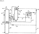
- a double air separation column comprising a first column K1 operating at a first pressure and a second column K2 operating at a second pressure, lower than the first pressure.
- the two columns are connected together thermally, for example by a condenser-reboiler C which vaporizes the bottom oxygen of the second column K2 by heat exchange with the gaseous nitrogen of the first column K1.
- a nitrogen-rich liquid 11 is sent from the top of the first column K1 to the top of the second column K2.
- the first column is supplied with gaseous air by an air flow 1 cooled and purified of water and CO2. Air can also be supplied to the second column K2.
- An oxygen-enriched liquid is withdrawn from the bottom of the first column K1 and divided into two. A part 3 is sent to the heat exchanger E where it is totally vaporized to form a gas 5.
- the gas 5 is expanded in a turbine T and sent to an intermediate point of the first column K1. The refrigeration production generated at very low temperature by this expansion therefore leads to a gain in the energy consumption of the unit, compared to what would be consumed in the absence of this expansion.
- the remainder of the oxygen-enriched liquid withdrawn from the tank is expanded in a valve and sent as flow 12 above the arrival points of the flows 5 and 9.
- the exchanger E contained in an enclosure B, also serves to liquefy an intermediate gas flow 7 from the second column K2.
- This gas 7 will be withdrawn at a position such that its condensation temperature (bubble point) will be higher than the vaporization temperature of the oxygen-enriched liquid 3 in the exchanger E.
- its composition will be that of the feed gas of an argon production column.
- An oxygen-rich liquid 15 is withdrawn from the bottom of the second column K2 and an overhead gas enriched in nitrogen 13 is withdrawn from the top of the same column.
- FIG. 1b all the tank liquid can be sent to exchanger E where it partially vaporizes.
- the partially condensed flow is separated in a phase separator 8 to produce a gas 5 and a liquid 100 enriched in oxygen relative to the liquid 3.
- the formed gas 5 is expanded in a turbine T and the remaining liquid 10 is expanded and sent to the column as fluid 12.
- the liquid enters the column K2 at a level above the gas of the turbine T since it has been enriched in oxygen.
- the Figure 1B illustrates only a modified part of the Figure 1a .
- the oxygen enriched liquid 3 is divided into three parts 3,17,19.
- Part 17 is sent directly to the second column K2 in liquid form.
- Part 3, as for Figure 1 heat exchange with a flow enriched in argon 7 which is part of the gas enriched in argon withdrawn from the second column, the rest of the gas 7A being sent directly to feed the argon separation column K3.
- Part 3 is vaporized to form the gas flow 5 at 2.1 bars, then expanded in the turbine T and sent to the column K2.
- the flow rate 7 condenses in the exchanger E contained in an enclosure B, and the liquid 9 formed feeds the column K3, preferably a few stages above the gas inlet 7A.
- the enclosure B is preferably arranged above the point of arrival of the liquid 9 in the column K3.
- Part 19 of the oxygen-enriched liquid feeds the head condenser N of column K3 without having been enriched in oxygen and vaporizes there to form a gas 23.
- the gas 23 is mixed with the gas expanded in the turbine T to form a gas 25 which feeds the second column K2.
- the oxygen-enriched liquid feeds the exchanger E and the head condenser N in parallel.
- the argon yield is of the order of 80%, if the oxygen purified argon (flow rate 21) is recovered as product. If the flow 21 is not recovered as a pure product, the column K3 can be very small, containing only a few tens of theoretical stages ( ⁇ 50), or even less than 10 theoretical stages.
- the oxygen-enriched liquid is only divided into two parts 3.3A.
- Part 3A feeds column K2 and part 3 is partially vaporized in heat exchanger E.
- the remaining liquid 3B feeds the overhead condenser N of column K3 and the gas 23 formed in the condenser feeds column K2.
- the gas 7A formed in the exchanger E feeds the turbine T at an inlet pressure of 2.7 bars.
- the argon yield is of the order of 75 to 76%, if the argon is recovered (flow rate 21).
- the argon column has a liquid feed in addition to the usual gas feed.
- the diameter of the column K3 can be reduced by about 20%, for the section above the inlet of the liquid 9, reducing its cost. Since the argon column is the highest column of the apparatus, it is important to be able to reduce its volume and thus reduce the dimensions of the cold box which contains it (not illustrated).
- column K3 of the Figures 2 and 3 can be inside column K2, arranged concentrically with the shell of column K2.
- Column K3 can contain structured packings or bulk packings.
- the gas rising in column K2 will pass either in column K3 or in the annular part surrounding column K2.
- the top condenser N of column K3 will be used in this case to heat a liquid bath located at mid-height of column K2.
- the gas from the top of column K3 will pass through a pipe in the top condenser N through a barrier forming a tank halfway up the column K2 and the liquid condensed in the condenser N will pass in the same way in another driving through the barrier to return to column K2.
- a valve can regulate the quantity of liquid returned from condenser N to column K2.
- Column K3 is surrounded by an annular section of column K2 where packings are located.
- the gas separated at the top of the annular section is sent to the column section K2 passing through the barrier in a pipe or will be sent outside the column below the barrier to enter the column above of the barrier.
- the bottom liquid accumulated above the barrier will be sent to the top of the annular section either by a pipe passing through the barrier or by a pipe connected to the outside of the column.
- the exchanger E in its enclosure B is still located outside the column K2 and outside the column K3.
- the flow rate 7 is withdrawn directly from the column K2, without being divided since the flow rate equivalent to 7A rises directly in the column K2 towards the column K3.
- liquid 3B is injected into column K2 to be directed to condenser N.
- a metal with better conductivity can be used for the upper part of the shell than for the upper part (for example aluminum at the top of the shell of the K3 column and stainless steel at the bottom of the column) .
- Another possibility is to use a full aluminum K3 ferrule and apply a coating in the lower section to reduce heat exchange.
- an argon separation column having an overhead condenser in a second column (low pressure column).
- One possibility is to position the overhead column so that the overhead gas of the argon column condenses partly in the overhead condenser of the argon column and partly in an overhead condenser of the low pressure column. by heat exchange with oxygen-rich liquid from the bottom of the first column (medium pressure column)
- the liquid formed in the top condenser of the second column is sent to the top of the second column and the vaporized liquid is sent to a level above the top condenser of the argon column.
- the overhead condenser can be a film vaporizer.
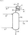
- the turbine T can be replaced by a mixing column K4 operating for example at between 2.2 and 2.7 bars, as illustrated in Figure 4 .
- This mixing column will be fed to the tank by the rich liquid vaporized 5 vaporized by the exchanger E.
- At the top of the column K4 arrives a flow of impure liquid oxygen. containing about 90 mol% oxygen.
- the rich vaporized liquid contains 34% oxygen for the case of the Figure 2 and 20% oxygen for the case of Figure 3 .
- a liquid 31 is withdrawn from the bottom of column K4 containing 65% oxygen (in the case of Figure 2 ) or 50% oxygen (case of Figure 3 ).
- a gas flow 43 is withdrawn in the middle of the column K4.
- the gas 35 can replace the gaseous nitrogen coming from the first column in the condenser C of the Figure 2 or 3 . This makes it possible to increase the argon yield by approximately 5% or to increase the production of nitrogen gas at the top of the first column.
- the Figure 5 further illustrates a variant of Figures 2 and 3 where the oxygen-enriched liquid 3 from the bottom of the first column is enriched with oxygen in an Etienne K5 column, the bottom reboiler E of which corresponds to the exchanger 3 of the preceding figures.
- the reboiler E is reheated by a gas flow 7 enriched in argon coming from the second argon column.
- the liquid flow product 9 serves as a second feed to the argon column K3 in addition to the gas feed.
- the liquid 3 expanded in a valve descends the stages of column K5 and is enriched with oxygen to produce a flow 53 rich in oxygen (75% oxygen), a vessel flow rate and an overhead gas containing only 16% oxygen.
- the flow 53 feeds the column K2 and allows a gain in argon yield of 3%.
Landscapes
- Engineering & Computer Science (AREA)
- Physics & Mathematics (AREA)
- Mechanical Engineering (AREA)
- Thermal Sciences (AREA)
- General Engineering & Computer Science (AREA)
- Separation By Low-Temperature Treatments (AREA)
- Health & Medical Sciences (AREA)
- Emergency Medicine (AREA)
Abstract
Description
- Selon la présente invention, il est prévu un procédé et un appareil de séparation d'air par distillation cryogénique. Le procédé est réalisé utilisant une double colonne de distillation d'air, en soi bien connue, associée ou non à une colonne de séparation d'argon.
- Classiquement dans un appareil de séparation d'air, de l'air épuré et refroidi est envoyé à une première colonne opérant à une température cryogénique pour être séparé en un gaz enrichi en azote et un liquide enrichi en oxygène.
- Le liquide est soutiré de la première colonne et envoyé à une deuxième colonne opérant à une pression plus basse que la première colonne, après détente dans une vanne.
- Les appareils de séparation d'air comprennent souvent une colonne de séparation d'argon en plus de la double colonne. Cette colonne de séparation d'argon peut évidemment servir à produire de l'argon mais dans certains cas, elle est installée surtout dans le but d'augmenter le rendement d'oxygène et/ou d'augmenter la production d'azote à une pression élevée et/ou de permettre de détendre beaucoup d'air destiné à la deuxième colonne pour augmenter la production de frigories et donc la production de liquide ou pour améliorer les performances énergétiques.
- Un but de la présente invention est d'améliorer la performance énergétique des unités de séparation d'air, avec ou sans la présence de la colonne de séparation d'argon.
- Dans le cas, où la colonne de séparation d'argon est présente, même si de l'argon n'est pas produit et/ou la colonne ne contient que très peu d'étages, l'invention vise à réduire le coût supplémentaire lié à la présence de cette colonne. Ainsi, le gain de performance énergétique amené par l'invention peut être totalement ou partiellement engrangé à moindre frais.
- Un procédé selon la partie caractérisante de la revendication 1 est connu de
EP-A-0860670 . Dans ce procédé, le liquide alimentant le condenseur de tête de la colonne d'argon ne provient pas directement de la première colonne, mais a subi au préalable une vaporisation partielle pour condenser la mixture argon. Comme le liquide se concentre ainsi en oxygène, sa température de vaporisation augmente. L'écart de température dans le condenseur de colonne argon est alors excessivement faible et demande un très gros volume d'échangeur. Cela a pour conséquence de grossir la boite froide. - Selon un objet de l'invention, il est prévu un procédé de séparation d'air par distillation cryogénique dans lequel
- a) De l'air refroidi et épuré en eau est envoyé à une première colonne opérant à une première pression où il est séparé en un gaz enrichi en azote et un liquide enrichi en oxygène,
- b) Un liquide enrichi en azote par rapport à l'air est soutiré de la première colonne et envoyé en haut d'une deuxième colonne thermiquement reliée à la première colonne et opérant à une deuxième pression inférieure à la première pression,
- c) Un liquide enrichi en oxygène par rapport à l'air est soutiré de la première colonne et éventuellement une première partie du liquide enrichi en oxygène est envoyée à un niveau intermédiaire de la deuxième colonne éventuellement après avoir subi une étape de vaporisation partielle qui l'a enrichie en oxygène
- d) Un gaz enrichi en argon par rapport à l'air est soutiré de la deuxième colonne
- e) Au moins une partie du liquide enrichi en oxygène est au moins partiellement vaporisée par échange de chaleur avec le gaz enrichi en argon et le liquide enrichi en oxygène vaporisé est envoyé à un niveau intermédiaire de la deuxième colonne, éventuellement suite à une étape d'enrichissement en oxygène du liquide vaporisé
- f) Au moins une partie condensée du gaz enrichi en argon est renvoyée à une troisième colonne qui est également alimentée par un débit gazeux enrichi en argon provenant de la deuxième colonne, un débit enrichi en argon est soutiré en tête de la troisième colonne et un liquide appauvri en argon est renvoyé de la troisième colonne à la deuxième colonne.
- g) Une partie du liquide enrichi en oxygène est envoyée à un condenseur de tête de la troisième colonne,
- h) Le liquide enrichi en oxygène envoyé au condenseur de tête s'y vaporise et la vapeur produite est envoyée à la deuxième colonne
- Selon d'autres aspects facultatifs qui peuvent être combinés entre eux :
- le liquide enrichi en oxygène vaporisé est à une pression d'au moins 1 bar supérieure à la pression de la deuxième colonne, et est détendu dans une turbine puis envoyé à un niveau intermédiaire de la deuxième colonne.
- au moins une partie condensée du gaz enrichi en argon est renvoyée à la deuxième colonne.
- au moins une partie condensée du gaz enrichi en argon est renvoyée à une troisième colonne qui est également alimentée par un débit gazeux enrichi en argon provenant de la deuxième colonne, un débit enrichi en argon est soutiré en tête de la troisième colonne et un liquide appauvri en argon est renvoyé de la troisième colonne à la deuxième colonne.
- la partie du liquide enrichi en oxygène envoyée au condenseur de tête de la troisième colonne n'a pas subi un enrichissement en oxygène
- la troisième colonne est disposée à l'intérieur de la deuxième colonne et l'au moins une partie du liquide enrichi en oxygène est vaporisée par échange de chaleur avec le gaz enrichi en argon à l'intérieur de la deuxième colonne.
- le gaz enrichi en argon envoyé à l'échangeur a une température de condensation supérieure à la température de vaporisation du liquide enrichi en oxygène dans l'échangeur.
- tout le liquide enrichi en oxygène est envoyé de la cuve de la première colonne à l'échangeur de chaleur, seule une partie du liquide est vaporisée et cette partie est envoyé à la deuxième colonne
- dans ce cas, la partie non-vaporisée est séparée dans un séparateur de phases, détendue et envoyée à la deuxième colonne
- une partie du liquide enrichi en oxygène est envoyée de la cuve de la première colonne à l'échangeur de chaleur où elle est au moins partiellement vaporisée et une partie du liquide enrichie en oxygène est envoyée de la cuve de la première colonne à la deuxième colonne sans passer par l'échangeur de chaleur.
- Tout le liquide enrichi en oxygène envoyé à l'échanger de chaleur s'y vaporise.
- Selon un autre objet de l'invention, il est prévu un appareil de séparation d'air par distillation cryogénique comprenant une première colonne opérant à une première pression, une deuxième colonne thermiquement reliée à la première colonne et opérant à une deuxième pression inférieure à la première pression, un échangeur de chaleur, des moyens pour envoyer de l'air refroidi et épuré en eau à la première colonne opérant à une première pression où il est séparé en un gaz enrichi en azote et un liquide enrichi en oxygène, des moyens pour soutirer un liquide enrichi en azote par rapport à l'air de la première colonne, des moyens pour envoyer le liquide enrichi en azote en haut de la deuxième colonne, des moyens pour soutirer un liquide enrichi en oxygène par rapport à l'air de la première colonne, éventuellement des moyens pour envoyer une première partie du liquide enrichie en oxygène à un niveau intermédiaire de la deuxième colonne, éventuellement après l'avoir enrichie en oxygène, des moyens pour soutirer un gaz enrichi en argon par rapport à l'air de la deuxième colonne, des moyens pour envoyer une partie du liquide enrichi en oxygène à l'échangeur de chaleur pour se vaporiser au moins partiellement par échange de chaleur avec le gaz enrichi en argon et des moyens pour envoyer le liquide enrichi en oxygène vaporisé dans l'échangeur de chaleur à un niveau intermédiaire de la deuxième colonne, éventuellement suite à une étape d'enrichissement en oxygène du liquide vaporisé, une troisième colonne, des moyens pour envoyer au moins une partie condensée du gaz enrichi en argon dans l'échangeur de chaleur à la troisième colonne et des moyens pour envoyer un débit gazeux enrichi en argon provenant de la deuxième colonne à la troisième colonne, des moyens pour soutirer un débit enrichi en argon en tête de la troisième colonne, des moyens pour renvoyer un liquide appauvri en argon de la troisième colonne à la deuxième colonne, des moyens pour envoyer une partie du liquide enrichi en oxygène à un condenseur de tête de la troisième colonne et des moyens pour envoyer la vapeur produite en vaporisant le liquide enrichi en oxygène dans le condenseur de tête à la deuxième colonne caractérisé en ce que les moyens pour envoyer la partie du liquide enrichi en oxygène au condenseur de tête sont reliés directement à la première colonne sans transiter par l'échangeur.
- Selon d'autres aspects facultatifs :
- l'appareil comprend une turbine reliée à un niveau intermédiaire de la deuxième colonne alimentée par le liquide enrichi en oxygène vaporisé.
- l'appareil comprend des moyens pour renvoyer au moins une partie condensée du gaz enrichi en argon est à la deuxième colonne .
- l'appareil comprend des moyens pour envoyer la vapeur produite à la deuxième colonne, en étant mélangée au débit détendu dans la turbine .
- la troisième colonne est disposée à l'intérieur de la deuxième colonne
- l'appareil comprend des moyens pour vaporiser l'au moins une partie du liquide enrichi en oxygène par échange de chaleur avec le gaz enrichi en argon à l'intérieur de la deuxième colonne.
- la troisième colonne contient moins que 50, voire moins que 10 étages théoriques. L'invention sera décrite de manière plus détaillée en se référant aux figures :
- [
Fig. 1 ] composée desfigures 1a et 1b représente des procédés comparatifs. - [
Fig. 2 ] représente des procédés selon l'invention. - [
Fig. 3 ] représente des procédés selon l'invention. - [
Fig. 4 ] représente une variante desFigures 2 et3 . - [
Fig. 5 ] représente également une variante desFigures 2 et3 .
- [
- Dans la
Figure 1a , on voit une double colonne de séparation d'air comprenant une première colonne K1 opérant à une première pression et une deuxième colonne K2 opérant à une deuxième pression, inférieure à la première pression. Les deux colonnes sont reliées ensemble thermiquement, par exemple par un condenseur-rebouilleur C qui vaporise l'oxygène de cuve de la deuxième colonne K2 par échange de chaleur avec l'azote gazeux de la première colonne K1. - Un liquide riche en azote 11 est envoyé de la tête de la première colonne K1 à la tête de la deuxième colonne K2. La première colonne est alimentée en air gazeux par un débit d'air 1 refroidi et épuré en eau et en CO2. De l'air peut également alimenter la deuxième colonne K2.
- Un liquide enrichi en oxygène est soutiré en cuve de la première colonne K1 et divisé en deux. Une partie 3 est envoyée à l'échangeur de chaleur E où elle est vaporisée totalement pour former un gaz 5. Le gaz 5 est détendu dans une turbine T et envoyé à un point intermédiaire de la première colonne K1. La production frigorifique générée à très basse température par cette détente amène donc un gain sur la consommation d'énergie de l'unité, comparativement à ce qui serait consommé en l'absence de cette détente.
- Le reste 10 du liquide enrichi en oxygène soutiré en cuve est détendu dans une vanne et envoyé comme débit 12 au-dessus des points d'arrivée des débits 5 et 9.
- L'échangeur E, contenu dans une enceinte B, sert aussi à liquéfier un débit de gaz intermédiaire 7 de la deuxième colonne K2. Ce gaz 7 sera soutiré à position telle que sa température de condensation (point de bulle) sera supérieure à la température de vaporisation du liquide enrichi en oxygène 3 dans l'échangeur E. Typiquement, sa composition sera celle du gaz d'alimentation d'une colonne de production d'argon. Après s'être condensé dans E, ce débit étant ensuite envoyé, éventuellement au moyen d'une pompe P, à un point au moins au-dessus de son point de soutirage et en dessous de l'arrivée de gaz détendu de la turbine T.
- Un liquide riche en oxygène 15 est soutiré de la cuve de la deuxième colonne K2 et un gaz de tête enrichi en azote 13 est soutiré de la tête de la même colonne.
- En variante, comme illustré dans la
Figure 1b , tout le liquide de cuve peut être envoyé à l'échangeur E où il se vaporise partiellement. Le débit partiellement condensé est séparé dans un séparateur de phases 8 pour produire un gaz 5 et un liquide 100 enrichi en oxygène par rapport au liquide 3. Le gaz formé 5 est détendu dans une turbine T et le liquide restant 10 est détendu et envoyé à la colonne comme fluide 12. Dans ce cas, le liquide entre la colonne K2 à un niveau en dessus du gaz de la turbine T puisqu'il a été enrichi en oxygène. LaFigure 1B n'illustre qu'une partie modifiée de laFigure 1a . - Ces schémas ne comprennent pas de colonne de séparation d'argon à la différence des
Figures 2 et3 . - Dans la
Figure 2 , variante de laFigure 1 , le liquide enrichi en oxygène 3 est divisé en trois parties 3,17,19. - Une partie 17 est envoyée directement à la deuxième colonne K2 sous forme liquide. La partie 3, comme pour la
Figure 1 , échange de la chaleur avec un débit enrichi en argon 7 qui est une partie du gaz enrichi en argon soutiré de la deuxième colonne, le reste du gaz 7A étant envoyé directement pour alimenter la colonne de séparation d'argon K3. - La partie 3 est vaporisée pour former le débit gazeux 5 à 2,1 bars, puis détendue dans la turbine T et envoyée à la colonne K2. Le débit 7 se condense dans l'échangeur E contenu dans une enceinte B, et le liquide formé 9 alimente la colonne K3, de préférence quelques étages au-dessus de l'arrivée de gaz 7A.
- L'enceinte B est de préférence disposée au-dessus du point d'arrivée du liquide 9 dans la colonne K3.
- La partie 19 du liquide enrichi en oxygène alimente le condenseur de tête N de la colonne K3 sans avoir été enrichi en oxygène et s'y vaporise pour former une gaz 23. Le gaz 23 est mélangé avec le gaz détendu dans la turbine T pour former un gaz 25 qui alimente la deuxième colonne K2.
- Ainsi le liquide enrichi en oxygène alimente l'échangeur E et le condenseur de tête N en parallèle.
- Le rendement en argon est de l'ordre de 80 %, si l'argon épuré en oxygène (débit 21) est récupéré comme produit. Si le débit 21 n'est pas récupéré comme produit pur, la colonne K3 peut être très petite, ne contenant que quelques dizaines d'étages théoriques (< 50), voire moins de 10 étages théoriques.
- Dans la
Figure 3 , le liquide enrichi en oxygène n'est divisé qu'en deux parties 3,3A. La partie 3A alimente la colonne K2 et la partie 3 est partiellement vaporisé dans l'échangeur de chaleur E. Le liquide restant 3B alimente le condenseur de tête N de la colonne K3 et le gaz formé 23 dans le condenseur alimente la colonne K2. - Le gaz 7A formé dans l'échangeur E alimente la turbine T à une pression d'entrée de 2,7 bars.
- Le rendement en argon est de l'ordre de 75 à 76 %, si l'argon est récupéré (débit 21). Dans les cas des
Figures 2 et3 , la colonne argon a une alimentation liquide en plus de l'habituelle alimentation gazeuse. Ainsi le diamètre de la colonne K3 peut être réduit d'environ 20%, pour la section au-dessus de l'arrivée du liquide 9, réduisant son coût. Etant donné que la colonne d'argon est la colonne la plus haute de l'appareil, il est important de pouvoir en réduire le volume et ainsi réduire les dimensions de la boîte froide qui la contient (non illustrée). - En variante, la colonne K3 des
Figures 2 et3 peut se trouver à l'intérieur de la colonne K2, disposée de manière concentrique avec la virole de la colonne K2. La colonne K3 peut contenir des garnissages structurés ou des garnissages en vrac. - Le gaz montant dans la colonne K2 passera soit dans la colonne K3 soit dans la partie annulaire entourant la colonne K2.
- Le condenseur de tête N de la colonne K3 servira dans ce cas à chauffer un bain de liquide situé à mi-hauteur de la colonne K2. Le gaz de la tête de la colonne K3 passera par une conduite dans le condenseur de tête N à travers une barrière formant une cuve à mi-hauteur de la colonne K2 et le liquide condensé dans le condenseur N passera de la même manière dans une autre conduite à travers la barrière pour revenir à la colonne K2. Une vanne peut régler la quantité de liquide renvoyé du condenseur N vers la colonne K2.
- La colonne K3 est entourée par une section annulaire de la colonne K2 où se trouvent des garnissages. Le gaz séparé en haut de la section annulaire est envoyé à la section de la colonne K2 en passant à travers la barrière dans une conduite ou sera envoyé à l'extérieur de la colonne en dessous de la barrière pour rentrer dans la colonne au-dessus de la barrière. Le liquide de cuve accumulé au-dessus de la barrière sera envoyé en haut de la section annulaire soit par une conduite passant à travers la barrière soit par une conduite reliée à l'extérieur de la colonne.
- Dans ce cas, l'échangeur E dans son enceinte B est situé toujours à l'extérieur de la colonne K2 et à l'extérieur de la colonne K3. Dans ce cas, le débit 7 est soutiré directement de la colonne K2, sans être divisé puisque le débit équivalent à 7A monte directement dans la colonne K2 vers la colonne K3.
- De même le liquide 3B est injecté dans la colonne K2 pour être dirigé vers le condenseur N.
- Pour une colonne concentrique K3 à l'intérieur d'une autre colonne K2, puisque les mélanges de fluides ne sont pas de composition identique de part et d'autre de la colonne intérieur K3, il y aura des échanges thermiques à travers la paroi de la colonne K2 entre l'intérieur de la colonne K2 et la partie annulaire. L'échange thermique favorise la distillation en haut de la colonne K2 alors qu'en bas de la colonne, l'échange thermique ne la favorise pas.
- Il est donc recommandé d'améliorer l'échange dans la partie supérieure de la colonne K3 en augmentant la surface d'échange thermique en rajoutant des ailettes sur la virole de la partie supérieure de la colonne K3.
- En alternatif on peut utiliser un métal de meilleure conductivité pour la partie supérieure de la virole que pour la partie supérieure (par exemple de l'aluminium en haut de la virole de la colonne K3 et de l'acier inoxydable en bas de la colonne). Une autre possibilité est d'utiliser une virole de K3 entièrement en aluminium et d'appliquer un revêtement dans la section inférieure pour réduire les échanges thermiques.
- Il a été proposé par le passé de disposer une colonne de séparation d'argon ayant un condenseur de tête dans une deuxième colonne (colonne basse pression). Une possibilité est de positionner la colonne de tête de sorte que le gaz de tête de la colonne d'argon se condense en partie dans la condenseur de tête de la colonne d'argon et en partie dans un condenseur de tête de la colonne basse pression par échange de chaleur avec du liquide riche en oxygène provenant de la cuve de la première colonne (colonne moyenne pression) Le liquide formé dans le condenseur de tête de la deuxième colonne est envoyé en tête de la deuxième colonne et le liquide vaporisé est envoyé à un niveau au-dessus du condenseur de tête de la colonne argon. Le condenseur de tête peut être un vaporiseur à film.
- Dans les
Figures 2 et3 , la turbine T peut être remplacée par une colonne de mélange K4 opérant par exemple à entre 2,2 et 2,7 bars, comme illustré à laFigure 4 . Cette colonne de mélange sera alimentée en cuve par le liquide riche vaporisé 5 vaporisé par l'échangeur E. En haut de la colonne K4 arrive un débit d'oxygène liquide impur contenant environ 90% mol d'oxygène. Le liquide riche vaporisé contient 34% d'oxygène pour le cas de laFigure 2 et 20% d'oxygène pour le cas de laFigure 3 . Un liquide 31 est soutiré en cuve de la colonne K4 contenant 65% d'oxygène (cas de laFigure 2 ) ou 50% d'oxygène (cas de laFigure 3 ). Un débit gazeux 43 est soutiré au milieu de la colonne K4. - La colonne K4 produit un débit 35 en tête de colonne contenant 75% d'oxygène (
Figure 2 ) ou 65% d'oxygène (Figure 3 ) à entre 2,1 et 2,7 bars. Ce débit est condensé dans un condenseur C qui peut être le condenseur de cuve de la deuxième colonne K2 ou un vaporiseur externe à toute colonne. Il se condense par échange de chaleur avec de l'oxygène liquide pur 39 ainsi produisant de l'oxygène gazeux pur 41. - Ainsi le gaz 35 peut remplacer l'azote gazeux provenant de la première colonne dans le condenseur C de la
Figure 2 ou3 . Ceci permet d'augmenter le rendement en argon d'environ 5% ou d'augmenter la production d'azote gazeux en tête de la première colonne. - Le gain d'énergie sera par contre réduit par rapport à celui des
Figures 2 et3 mais la machine tournante T est éliminée. - La
Figure 5 illustre encore une variante desFigures 2 et3 où le liquide enrichi en oxygène 3 de la cuve de la première colonne est enrichi en oxygène dans une colonne Etienne K5 dont le rebouilleur de cuve E correspond à l'échangeur 3 des figures précédentes. - Ainsi le rebouilleur E est réchauffé par un débit gazeux 7 enrichi en argon provenant de la deuxième colonne argon. Le débit liquide produit 9 sert de deuxième alimentation à la colonne argon K3 en plus de l'alimentation gazeuse.
- Le liquide 3 détendu dans une vanne descend les étages de la colonne K5 et s'enrichit en oxygène pour produire un débit 53 riche en oxygène (75% oxygène), un débit de cuve et un gaz de tête ne contenant que 16% oxygène. Le débit 53 alimente la colonne K2 et permet un gain de rendement d'argon de 3%.
Claims (13)
- Procédé de séparation d'air par distillation cryogénique dans lequela) De l'air (1) refroidi et épuré en eau est envoyé à une première colonne (K1) opérant à une première pression où il est séparé en un gaz enrichi en azote et un liquide (3) enrichi en oxygène,b) Un liquide enrichi en azote (11) par rapport à l'air est soutiré de la première colonne et envoyé en haut d'une deuxième colonne (K2) thermiquement reliée à la première colonne et opérant à une deuxième pression inférieure à la première pression,c) Un liquide enrichi en oxygène (3) par rapport à l'air est soutiré de la première colonne et éventuellement une première partie (10,17) du liquide enrichi en oxygène est envoyée à un niveau intermédiaire de la deuxième colonne éventuellement après avoir subi une étape de vaporisation partielle qui l'a enrichie en oxygèned) Un gaz enrichi en argon (7) par rapport à l'air est soutiré de la deuxième colonnee) Au moins une partie du liquide enrichi en oxygène est au moins partiellement vaporisée par échange de chaleur avec le gaz enrichi en argon et le liquide enrichi en oxygène vaporisé (5) est envoyé à un niveau intermédiaire de la deuxième colonne, éventuellement suite à une étape d'enrichissement en oxygène (K4) du liquide vaporiséf) Au moins une partie condensée (9) du gaz enrichi en argon est renvoyée à une troisième colonne (K3) qui est également alimentée par un débit gazeux enrichi en argon (7A) provenant de la deuxième colonne (K2), un débit enrichi en argon (21) est soutiré en tête de la troisième colonne et un liquide appauvri en argon est renvoyé de la troisième colonne à la deuxième colonne.g) Une partie (19) du liquide enrichi en oxygène est envoyée à un condenseur de tête (N) de la troisième colonne (K3),h) Le liquide enrichi en oxygène envoyé au condenseur de tête s'y vaporise et la vapeur produite (23) est envoyée à la deuxième colonnecaractérisé en ce que la partie (19) du liquide enrichi en oxygène envoyée au condenseur de tête (N) de la troisième colonne (K3) n'a pas été réchauffée contre le débit gazeux enrichi en argon (7).
- Procédé selon la revendication 1 dans lequel le liquide enrichi en oxygène vaporisé (5) est à une pression d'au moins 1 bar supérieure à la pression de la deuxième colonne (K2), et est détendu dans une turbine (T) puis envoyé à un niveau intermédiaire de la deuxième colonne.
- Procédé selon la revendication 1 ou 2 dans lequel au moins une partie condensée (9) du gaz enrichi en argon est renvoyée à la deuxième colonne (K2).
- Procédé selon la revendication 1 ou 2 dans lequel la vapeur produite (23) est envoyée à la deuxième colonne, en étant mélangée au débit détendu dans la turbine (T).
- Procédé selon la revendication 1 dans lequel la troisième colonne (K3) est disposée à l'intérieur de la deuxième colonne (K2) et l'au moins une partie du liquide enrichi en oxygène est vaporisée par échange de chaleur avec le gaz enrichi en argon à l'intérieur de la deuxième colonne.
- Procédé selon l'une des revendications précédentes dans lequel le gaz enrichi en argon (7), envoyé à l'échangeur (E) où s'effectue l'échange de chaleur, à une température de condensation supérieure à la température de vaporisation du liquide enrichi en oxygène (3) dans l'échangeur.
- Appareil de séparation d'air par distillation cryogénique comprenant une première colonne (K1) opérant à une première pression, une deuxième colonne (K2) thermiquement reliée à la première colonne et opérant à une deuxième pression inférieure à la première pression, un échangeur de chaleur (E), des moyens pour envoyer de l'air (1) refroidi et épuré en eau à la première colonne opérant à une première pression où il est séparé en un gaz enrichi en azote et un liquide enrichi en oxygène, des moyens pour soutirer un liquide enrichi en azote (11) par rapport à l'air de la première colonne, des moyens pour envoyer le liquide enrichie en azote en haut de la deuxième colonne, des moyens pour soutirer un liquide enrichi en oxygène par rapport à l'air de la première colonne, éventuellement des moyens pour envoyer une première partie (10,17) du liquide enrichie en oxygène à un niveau intermédiaire de la deuxième colonne, éventuellement après l'avoir enrichie en oxygène, des moyens pour soutirer un gaz enrichi en argon (7) par rapport à l'air de la deuxième colonne, des moyens pour envoyer une partie (3) du liquide enrichi en oxygène à l'échangeur de chaleur pour se vaporiser au moins partiellement par échange de chaleur avec le gaz enrichi en argon et des moyens pour envoyer le liquide enrichi en oxygène vaporisé (5) dans l'échangeur de chaleur à un niveau intermédiaire de la deuxième colonne, éventuellement suite à une étape d'enrichissement en oxygène du liquide vaporisé, une troisième colonne (K3), des moyens pour envoyer au moins une partie condensée (9) du gaz enrichi en argon dans l'échangeur de chaleur à la troisième colonne et des moyens pour envoyer un débit gazeux enrichi en argon (7A) provenant de la deuxième colonne à la troisième colonne, des moyens pour soutirer un débit enrichi en argon (21) en tête de la troisième colonne, des moyens pour renvoyer un liquide appauvri en argon de la troisième colonne à la deuxième colonne, des moyens pour envoyer une partie (19) du liquide enrichi en oxygène à un condenseur de tête (N) de la troisième colonne (K3) et des moyens pour envoyer la vapeur produite (23) en vaporisant le liquide enrichi en oxygène dans le condenseur de tête à la deuxième colonne caractérisé en ce que les moyens pour envoyer la partie du liquide enrichi en oxygène au condenseur de tête sont reliés directement à la première colonne sans transiter par l'échangeur (E).
- Appareil selon la revendication 7 comprenant une turbine (T) reliée à un niveau intermédiaire de la deuxième colonne (K2) alimentée par le liquide enrichi en oxygène vaporisé (5).
- Appareil selon la revendication 7 ou 8 comprenant des moyens pour renvoyer au moins une partie condensée (9) du gaz enrichi en argon est à la deuxième colonne (K2).
- Appareil selon la revendication 7 et 8 comprenant des moyens pour envoyer la vapeur produite (23) à la deuxième colonne, en étant mélangée au débit détendu dans la turbine (T).
- Appareil selon l'une des revendications 7 à 10 dans lequel la troisième colonne (K3) est disposée à l'intérieur de la deuxième colonne (K2) et comprenant des moyens pour vaporiser l'au moins une partie du liquide enrichi en oxygène par échange de chaleur avec le gaz enrichi en argon à l'intérieur de la deuxième colonne.
- Appareil selon l'une des revendications 7 à 11 où la troisième colonne contient moins que 50 étages théoriques.
- Appareil selon la revendication 12 où la troisième colonne contient moins que 10 étages théoriques.
Applications Claiming Priority (1)
| Application Number | Priority Date | Filing Date | Title |
|---|---|---|---|
| FR1911900A FR3102548B1 (fr) | 2019-10-24 | 2019-10-24 | Procédé et appareil de séparation d’air par distillation cryogénique |
Publications (2)
| Publication Number | Publication Date |
|---|---|
| EP3812675A1 true EP3812675A1 (fr) | 2021-04-28 |
| EP3812675B1 EP3812675B1 (fr) | 2026-01-14 |
Family
ID=69190990
Family Applications (1)
| Application Number | Title | Priority Date | Filing Date |
|---|---|---|---|
| EP20203664.6A Active EP3812675B1 (fr) | 2019-10-24 | 2020-10-23 | Procédé et appareil de séparation d'air par distillation cryogénique |
Country Status (4)
| Country | Link |
|---|---|
| US (1) | US20210123671A1 (fr) |
| EP (1) | EP3812675B1 (fr) |
| CN (1) | CN112710125A (fr) |
| FR (1) | FR3102548B1 (fr) |
Families Citing this family (1)
| Publication number | Priority date | Publication date | Assignee | Title |
|---|---|---|---|---|
| CN113654302B (zh) * | 2021-08-12 | 2023-02-24 | 乔治洛德方法研究和开发液化空气有限公司 | 一种低温空气分离的装置和方法 |
Citations (5)
| Publication number | Priority date | Publication date | Assignee | Title |
|---|---|---|---|---|
| JPS54126672A (en) * | 1978-03-27 | 1979-10-02 | Hitachi Ltd | Air separator |
| EP0538520A1 (fr) * | 1991-10-22 | 1993-04-28 | Odessky Institut Nizkotemperaturnoi Tekhniki I Energetiki | Procédé de séparation d'air |
| EP0841525A2 (fr) * | 1996-11-11 | 1998-05-13 | The BOC Group plc | Séparation d'air |
| EP0860670A2 (fr) | 1997-02-11 | 1998-08-26 | Air Products And Chemicals, Inc. | Séparation d'air avec évaporation et expansion d'un fluide sous pression intermédiaire |
| EP1108965A1 (fr) * | 1999-12-13 | 2001-06-20 | Air Products And Chemicals, Inc. | Procédé de distillation d'un mélange convenant pour la production d'un courant enrichi en argon dans un procédé cryogénique de séparation de l'air |
Family Cites Families (8)
| Publication number | Priority date | Publication date | Assignee | Title |
|---|---|---|---|---|
| US4832719A (en) * | 1987-06-02 | 1989-05-23 | Erickson Donald C | Enhanced argon recovery from intermediate linboil |
| US4994098A (en) * | 1990-02-02 | 1991-02-19 | Air Products And Chemicals, Inc. | Production of oxygen-lean argon from air |
| GB9609099D0 (en) * | 1996-05-01 | 1996-07-03 | Boc Group Plc | Oxygen steelmaking |
| DE10113790A1 (de) * | 2001-03-21 | 2002-09-26 | Linde Ag | Drei-Säulen-System zur Tieftemperatur-Luftzerlegung |
| US7487648B2 (en) * | 2006-03-10 | 2009-02-10 | Praxair Technology, Inc. | Cryogenic air separation method with temperature controlled condensed feed air |
| US20130019634A1 (en) * | 2011-07-18 | 2013-01-24 | Henry Edward Howard | Air separation method and apparatus |
| CN107580670B (zh) * | 2015-03-13 | 2020-02-28 | 林德股份公司 | 通过低温空气分离制备氧的设备 |
| EP3343158A1 (fr) * | 2016-12-28 | 2018-07-04 | Linde Aktiengesellschaft | Procédé de production d'un ou plusieurs produits pneumatiques et unité de fractionnement d'air |
-
2019
- 2019-10-24 FR FR1911900A patent/FR3102548B1/fr active Active
-
2020
- 2020-10-21 US US17/076,487 patent/US20210123671A1/en not_active Abandoned
- 2020-10-23 EP EP20203664.6A patent/EP3812675B1/fr active Active
- 2020-10-26 CN CN202011154571.2A patent/CN112710125A/zh active Pending
Patent Citations (5)
| Publication number | Priority date | Publication date | Assignee | Title |
|---|---|---|---|---|
| JPS54126672A (en) * | 1978-03-27 | 1979-10-02 | Hitachi Ltd | Air separator |
| EP0538520A1 (fr) * | 1991-10-22 | 1993-04-28 | Odessky Institut Nizkotemperaturnoi Tekhniki I Energetiki | Procédé de séparation d'air |
| EP0841525A2 (fr) * | 1996-11-11 | 1998-05-13 | The BOC Group plc | Séparation d'air |
| EP0860670A2 (fr) | 1997-02-11 | 1998-08-26 | Air Products And Chemicals, Inc. | Séparation d'air avec évaporation et expansion d'un fluide sous pression intermédiaire |
| EP1108965A1 (fr) * | 1999-12-13 | 2001-06-20 | Air Products And Chemicals, Inc. | Procédé de distillation d'un mélange convenant pour la production d'un courant enrichi en argon dans un procédé cryogénique de séparation de l'air |
Also Published As
| Publication number | Publication date |
|---|---|
| CN112710125A (zh) | 2021-04-27 |
| FR3102548A1 (fr) | 2021-04-30 |
| US20210123671A1 (en) | 2021-04-29 |
| FR3102548B1 (fr) | 2023-03-10 |
| EP3812675B1 (fr) | 2026-01-14 |
Similar Documents
| Publication | Publication Date | Title |
|---|---|---|
| EP2158437A2 (fr) | Procede et appareil de separation cryogenique d'un debit riche en methane | |
| EP2932177A2 (fr) | Procédé et appareil de séparation d'un mélange contenant du dioxyde de carbone par distillation | |
| EP2137474B1 (fr) | Procede et appareil de production de monoxyde de carbone par distillation cryogenique | |
| FR2844039A1 (fr) | Procede et installation de production d'oxygene et de gaz rares par distillation cryogenique d'air | |
| EP2694898B1 (fr) | Procédé et appareil de séparation d'air par distillation cryogénique | |
| EP2149021B1 (fr) | Capacité de stockage, appareil et procédé de production de monoxyde de carbone et/ou d'hydrogène par séparation cryogénique intégrant une telle capacité | |
| EP3069091A2 (fr) | Procédé et appareil de séparation d'air par distillation cryogénique | |
| EP1189003B1 (fr) | Procédé et installation de séparation d'air par distillation cryogénique | |
| EP3812675B1 (fr) | Procédé et appareil de séparation d'air par distillation cryogénique | |
| EP3350119B1 (fr) | Procédé et appareil de production d'un mélange de monoxyde de carbone et d'hydrogène | |
| EP3599438A1 (fr) | Procede et appareil de separation cryogenique d'un melange de monoxyde de carbone, d'hydrogene et de methane pour la production de ch4 | |
| EP1966554B1 (fr) | Appareil de séparation d'air par distillation cryogénique | |
| FR2990019A1 (fr) | Procede et appareil de separation d'air par distillation cryogenique | |
| FR2973485A1 (fr) | Procede et appareil de separation d'air par distillation cryogenique | |
| EP1697690A2 (fr) | Procede et installation d enrichissement d'un flux gazeux en l'un de ses constituants | |
| FR2795496A1 (fr) | Appareil et procede de separation d'air par distillation cryogenique | |
| EP4285061B1 (fr) | Procédé et appareil de séparation d'un débit riche en dioxyde de carbone par distillation pour produire du dioxyde de carbone liquide | |
| EP0884543A1 (fr) | Procédé et installation de séparation d'air par distillation cryogénique | |
| WO2005045339A1 (fr) | Procédé et appareil de séparation d'air par distillation cryogénique | |
| FR2947898A1 (fr) | Procede de separation d'air par distillation cryogenique | |
| FR3020867A1 (fr) | Procede et appareil de separation d’air par distillation cryogenique pour la production d’un melange de krypton et de xenon | |
| EP3913310A1 (fr) | Procédé et appareil de séparation d'air par distillation cryogénique | |
| FR2974890A1 (fr) | Procede et appareil de separation d'air par distillation cryogenique. | |
| FR3058996A1 (fr) | Procede et installation de separation cryogenique d’un melange gazeux par lavage au methane |
Legal Events
| Date | Code | Title | Description |
|---|---|---|---|
| PUAI | Public reference made under article 153(3) epc to a published international application that has entered the european phase |
Free format text: ORIGINAL CODE: 0009012 |
|
| STAA | Information on the status of an ep patent application or granted ep patent |
Free format text: STATUS: THE APPLICATION HAS BEEN PUBLISHED |
|
| AK | Designated contracting states |
Kind code of ref document: A1 Designated state(s): AL AT BE BG CH CY CZ DE DK EE ES FI FR GB GR HR HU IE IS IT LI LT LU LV MC MK MT NL NO PL PT RO RS SE SI SK SM TR |
|
| AX | Request for extension of the european patent |
Extension state: BA ME |
|
| STAA | Information on the status of an ep patent application or granted ep patent |
Free format text: STATUS: REQUEST FOR EXAMINATION WAS MADE |
|
| 17P | Request for examination filed |
Effective date: 20211028 |
|
| RBV | Designated contracting states (corrected) |
Designated state(s): AL AT BE BG CH CY CZ DE DK EE ES FI FR GB GR HR HU IE IS IT LI LT LU LV MC MK MT NL NO PL PT RO RS SE SI SK SM TR |
|
| GRAP | Despatch of communication of intention to grant a patent |
Free format text: ORIGINAL CODE: EPIDOSNIGR1 |
|
| STAA | Information on the status of an ep patent application or granted ep patent |
Free format text: STATUS: GRANT OF PATENT IS INTENDED |
|
| RIC1 | Information provided on ipc code assigned before grant |
Ipc: F25J 3/04 20060101AFI20250410BHEP |
|
| INTG | Intention to grant announced |
Effective date: 20250502 |
|
| GRAJ | Information related to disapproval of communication of intention to grant by the applicant or resumption of examination proceedings by the epo deleted |
Free format text: ORIGINAL CODE: EPIDOSDIGR1 |
|
| STAA | Information on the status of an ep patent application or granted ep patent |
Free format text: STATUS: REQUEST FOR EXAMINATION WAS MADE |
|
| GRAP | Despatch of communication of intention to grant a patent |
Free format text: ORIGINAL CODE: EPIDOSNIGR1 |
|
| STAA | Information on the status of an ep patent application or granted ep patent |
Free format text: STATUS: GRANT OF PATENT IS INTENDED |
|
| INTC | Intention to grant announced (deleted) | ||
| INTG | Intention to grant announced |
Effective date: 20250804 |
|
| GRAJ | Information related to disapproval of communication of intention to grant by the applicant or resumption of examination proceedings by the epo deleted |
Free format text: ORIGINAL CODE: EPIDOSDIGR1 |
|
| STAA | Information on the status of an ep patent application or granted ep patent |
Free format text: STATUS: REQUEST FOR EXAMINATION WAS MADE |
|
| GRAP | Despatch of communication of intention to grant a patent |
Free format text: ORIGINAL CODE: EPIDOSNIGR1 |
|
| STAA | Information on the status of an ep patent application or granted ep patent |
Free format text: STATUS: GRANT OF PATENT IS INTENDED |
|
| GRAS | Grant fee paid |
Free format text: ORIGINAL CODE: EPIDOSNIGR3 |
|
| INTC | Intention to grant announced (deleted) | ||
| GRAA | (expected) grant |
Free format text: ORIGINAL CODE: 0009210 |
|
| STAA | Information on the status of an ep patent application or granted ep patent |
Free format text: STATUS: THE PATENT HAS BEEN GRANTED |
|
| INTG | Intention to grant announced |
Effective date: 20251114 |
|
| AK | Designated contracting states |
Kind code of ref document: B1 Designated state(s): AL AT BE BG CH CY CZ DE DK EE ES FI FR GB GR HR HU IE IS IT LI LT LU LV MC MK MT NL NO PL PT RO RS SE SI SK SM TR |
|
| REG | Reference to a national code |
Ref country code: CH Ref legal event code: F10 Free format text: ST27 STATUS EVENT CODE: U-0-0-F10-F00 (AS PROVIDED BY THE NATIONAL OFFICE) Effective date: 20260114 Ref country code: GB Ref legal event code: FG4D Free format text: NOT ENGLISH |
|
| REG | Reference to a national code |
Ref country code: DE Ref legal event code: R096 Ref document number: 602020065443 Country of ref document: DE |
|
| REG | Reference to a national code |
Ref country code: IE Ref legal event code: FG4D Free format text: LANGUAGE OF EP DOCUMENT: FRENCH |
|
| REG | Reference to a national code |
Ref country code: NL Ref legal event code: FP |