EP0538520A1 - Procédé de séparation d'air - Google Patents
Procédé de séparation d'air Download PDFInfo
- Publication number
- EP0538520A1 EP0538520A1 EP91309755A EP91309755A EP0538520A1 EP 0538520 A1 EP0538520 A1 EP 0538520A1 EP 91309755 A EP91309755 A EP 91309755A EP 91309755 A EP91309755 A EP 91309755A EP 0538520 A1 EP0538520 A1 EP 0538520A1
- Authority
- EP
- European Patent Office
- Prior art keywords
- nitrogen
- argon
- fraction
- line
- air
- Prior art date
- Legal status (The legal status is an assumption and is not a legal conclusion. Google has not performed a legal analysis and makes no representation as to the accuracy of the status listed.)
- Ceased
Links
- 238000000034 method Methods 0.000 title claims abstract description 49
- 238000000926 separation method Methods 0.000 title claims description 33
- IJGRMHOSHXDMSA-UHFFFAOYSA-N Atomic nitrogen Chemical compound N#N IJGRMHOSHXDMSA-UHFFFAOYSA-N 0.000 claims abstract description 208
- XKRFYHLGVUSROY-UHFFFAOYSA-N Argon Chemical compound [Ar] XKRFYHLGVUSROY-UHFFFAOYSA-N 0.000 claims abstract description 206
- 229910052786 argon Inorganic materials 0.000 claims abstract description 103
- 229910052757 nitrogen Inorganic materials 0.000 claims abstract description 81
- QVGXLLKOCUKJST-UHFFFAOYSA-N atomic oxygen Chemical compound [O] QVGXLLKOCUKJST-UHFFFAOYSA-N 0.000 claims abstract description 49
- 239000001301 oxygen Substances 0.000 claims abstract description 49
- 229910052760 oxygen Inorganic materials 0.000 claims abstract description 49
- 229910001873 dinitrogen Inorganic materials 0.000 claims abstract description 46
- PWKWDCOTNGQLID-UHFFFAOYSA-N [N].[Ar] Chemical compound [N].[Ar] PWKWDCOTNGQLID-UHFFFAOYSA-N 0.000 claims abstract description 36
- 239000007788 liquid Substances 0.000 claims description 74
- 238000009835 boiling Methods 0.000 claims description 30
- 239000002826 coolant Substances 0.000 claims description 13
- 238000001704 evaporation Methods 0.000 claims description 12
- 230000008020 evaporation Effects 0.000 claims description 11
- 238000007906 compression Methods 0.000 claims description 8
- 230000006835 compression Effects 0.000 claims description 8
- 238000000746 purification Methods 0.000 claims description 7
- 238000001816 cooling Methods 0.000 claims description 6
- 238000010438 heat treatment Methods 0.000 claims description 3
- 238000011084 recovery Methods 0.000 description 14
- CURLTUGMZLYLDI-UHFFFAOYSA-N Carbon dioxide Chemical compound O=C=O CURLTUGMZLYLDI-UHFFFAOYSA-N 0.000 description 8
- 239000007789 gas Substances 0.000 description 5
- 238000004519 manufacturing process Methods 0.000 description 5
- 229910002092 carbon dioxide Inorganic materials 0.000 description 4
- 239000001569 carbon dioxide Substances 0.000 description 4
- 229930195733 hydrocarbon Natural products 0.000 description 4
- 150000002430 hydrocarbons Chemical class 0.000 description 4
- 230000002708 enhancing effect Effects 0.000 description 3
- 239000000203 mixture Substances 0.000 description 3
- 238000010992 reflux Methods 0.000 description 3
- MYMOFIZGZYHOMD-UHFFFAOYSA-N Dioxygen Chemical compound O=O MYMOFIZGZYHOMD-UHFFFAOYSA-N 0.000 description 2
- 230000007423 decrease Effects 0.000 description 2
- 229910052743 krypton Inorganic materials 0.000 description 2
- DNNSSWSSYDEUBZ-UHFFFAOYSA-N krypton atom Chemical compound [Kr] DNNSSWSSYDEUBZ-UHFFFAOYSA-N 0.000 description 2
- 229910052754 neon Inorganic materials 0.000 description 2
- GKAOGPIIYCISHV-UHFFFAOYSA-N neon atom Chemical compound [Ne] GKAOGPIIYCISHV-UHFFFAOYSA-N 0.000 description 2
- QJGQUHMNIGDVPM-UHFFFAOYSA-N nitrogen group Chemical group [N] QJGQUHMNIGDVPM-UHFFFAOYSA-N 0.000 description 2
- 238000001179 sorption measurement Methods 0.000 description 2
- 229910052724 xenon Inorganic materials 0.000 description 2
- FHNFHKCVQCLJFQ-UHFFFAOYSA-N xenon atom Chemical compound [Xe] FHNFHKCVQCLJFQ-UHFFFAOYSA-N 0.000 description 2
- 230000015572 biosynthetic process Effects 0.000 description 1
- 238000009903 catalytic hydrogenation reaction Methods 0.000 description 1
- 238000004140 cleaning Methods 0.000 description 1
- 238000007796 conventional method Methods 0.000 description 1
- 238000004821 distillation Methods 0.000 description 1
- 238000011089 mechanical engineering Methods 0.000 description 1
- 238000004172 nitrogen cycle Methods 0.000 description 1
- 230000035945 sensitivity Effects 0.000 description 1
- 239000000126 substance Substances 0.000 description 1
Images


Classifications
-
- F—MECHANICAL ENGINEERING; LIGHTING; HEATING; WEAPONS; BLASTING
- F25—REFRIGERATION OR COOLING; COMBINED HEATING AND REFRIGERATION SYSTEMS; HEAT PUMP SYSTEMS; MANUFACTURE OR STORAGE OF ICE; LIQUEFACTION SOLIDIFICATION OF GASES
- F25J—LIQUEFACTION, SOLIDIFICATION OR SEPARATION OF GASES OR GASEOUS OR LIQUEFIED GASEOUS MIXTURES BY PRESSURE AND COLD TREATMENT OR BY BRINGING THEM INTO THE SUPERCRITICAL STATE
- F25J3/00—Processes or apparatus for separating the constituents of gaseous or liquefied gaseous mixtures involving the use of liquefaction or solidification
- F25J3/02—Processes or apparatus for separating the constituents of gaseous or liquefied gaseous mixtures involving the use of liquefaction or solidification by rectification, i.e. by continuous interchange of heat and material between a vapour stream and a liquid stream
- F25J3/04—Processes or apparatus for separating the constituents of gaseous or liquefied gaseous mixtures involving the use of liquefaction or solidification by rectification, i.e. by continuous interchange of heat and material between a vapour stream and a liquid stream for air
- F25J3/04763—Start-up or control of the process; Details of the apparatus used
- F25J3/04769—Operation, control and regulation of the process; Instrumentation within the process
- F25J3/04812—Different modes, i.e. "runs" of operation
- F25J3/04836—Variable air feed, i.e. "load" or product demand during specified periods, e.g. during periods with high respectively low power costs
-
- F—MECHANICAL ENGINEERING; LIGHTING; HEATING; WEAPONS; BLASTING
- F25—REFRIGERATION OR COOLING; COMBINED HEATING AND REFRIGERATION SYSTEMS; HEAT PUMP SYSTEMS; MANUFACTURE OR STORAGE OF ICE; LIQUEFACTION SOLIDIFICATION OF GASES
- F25J—LIQUEFACTION, SOLIDIFICATION OR SEPARATION OF GASES OR GASEOUS OR LIQUEFIED GASEOUS MIXTURES BY PRESSURE AND COLD TREATMENT OR BY BRINGING THEM INTO THE SUPERCRITICAL STATE
- F25J3/00—Processes or apparatus for separating the constituents of gaseous or liquefied gaseous mixtures involving the use of liquefaction or solidification
- F25J3/02—Processes or apparatus for separating the constituents of gaseous or liquefied gaseous mixtures involving the use of liquefaction or solidification by rectification, i.e. by continuous interchange of heat and material between a vapour stream and a liquid stream
- F25J3/04—Processes or apparatus for separating the constituents of gaseous or liquefied gaseous mixtures involving the use of liquefaction or solidification by rectification, i.e. by continuous interchange of heat and material between a vapour stream and a liquid stream for air
- F25J3/04248—Generation of cold for compensating heat leaks or liquid production, e.g. by Joule-Thompson expansion
- F25J3/04284—Generation of cold for compensating heat leaks or liquid production, e.g. by Joule-Thompson expansion using internal refrigeration by open-loop gas work expansion, e.g. of intermediate or oxygen enriched (waste-)streams
- F25J3/0429—Generation of cold for compensating heat leaks or liquid production, e.g. by Joule-Thompson expansion using internal refrigeration by open-loop gas work expansion, e.g. of intermediate or oxygen enriched (waste-)streams of feed air, e.g. used as waste or product air or expanded into an auxiliary column
- F25J3/04296—Claude expansion, i.e. expanded into the main or high pressure column
-
- F—MECHANICAL ENGINEERING; LIGHTING; HEATING; WEAPONS; BLASTING
- F25—REFRIGERATION OR COOLING; COMBINED HEATING AND REFRIGERATION SYSTEMS; HEAT PUMP SYSTEMS; MANUFACTURE OR STORAGE OF ICE; LIQUEFACTION SOLIDIFICATION OF GASES
- F25J—LIQUEFACTION, SOLIDIFICATION OR SEPARATION OF GASES OR GASEOUS OR LIQUEFIED GASEOUS MIXTURES BY PRESSURE AND COLD TREATMENT OR BY BRINGING THEM INTO THE SUPERCRITICAL STATE
- F25J3/00—Processes or apparatus for separating the constituents of gaseous or liquefied gaseous mixtures involving the use of liquefaction or solidification
- F25J3/02—Processes or apparatus for separating the constituents of gaseous or liquefied gaseous mixtures involving the use of liquefaction or solidification by rectification, i.e. by continuous interchange of heat and material between a vapour stream and a liquid stream
- F25J3/04—Processes or apparatus for separating the constituents of gaseous or liquefied gaseous mixtures involving the use of liquefaction or solidification by rectification, i.e. by continuous interchange of heat and material between a vapour stream and a liquid stream for air
- F25J3/04248—Generation of cold for compensating heat leaks or liquid production, e.g. by Joule-Thompson expansion
- F25J3/04333—Generation of cold for compensating heat leaks or liquid production, e.g. by Joule-Thompson expansion using quasi-closed loop internal vapor compression refrigeration cycles, e.g. of intermediate or oxygen enriched (waste-)streams
- F25J3/04351—Generation of cold for compensating heat leaks or liquid production, e.g. by Joule-Thompson expansion using quasi-closed loop internal vapor compression refrigeration cycles, e.g. of intermediate or oxygen enriched (waste-)streams of nitrogen
-
- F—MECHANICAL ENGINEERING; LIGHTING; HEATING; WEAPONS; BLASTING
- F25—REFRIGERATION OR COOLING; COMBINED HEATING AND REFRIGERATION SYSTEMS; HEAT PUMP SYSTEMS; MANUFACTURE OR STORAGE OF ICE; LIQUEFACTION SOLIDIFICATION OF GASES
- F25J—LIQUEFACTION, SOLIDIFICATION OR SEPARATION OF GASES OR GASEOUS OR LIQUEFIED GASEOUS MIXTURES BY PRESSURE AND COLD TREATMENT OR BY BRINGING THEM INTO THE SUPERCRITICAL STATE
- F25J3/00—Processes or apparatus for separating the constituents of gaseous or liquefied gaseous mixtures involving the use of liquefaction or solidification
- F25J3/02—Processes or apparatus for separating the constituents of gaseous or liquefied gaseous mixtures involving the use of liquefaction or solidification by rectification, i.e. by continuous interchange of heat and material between a vapour stream and a liquid stream
- F25J3/04—Processes or apparatus for separating the constituents of gaseous or liquefied gaseous mixtures involving the use of liquefaction or solidification by rectification, i.e. by continuous interchange of heat and material between a vapour stream and a liquid stream for air
- F25J3/04406—Processes or apparatus for separating the constituents of gaseous or liquefied gaseous mixtures involving the use of liquefaction or solidification by rectification, i.e. by continuous interchange of heat and material between a vapour stream and a liquid stream for air using a dual pressure main column system
- F25J3/04412—Processes or apparatus for separating the constituents of gaseous or liquefied gaseous mixtures involving the use of liquefaction or solidification by rectification, i.e. by continuous interchange of heat and material between a vapour stream and a liquid stream for air using a dual pressure main column system in a classical double column flowsheet, i.e. with thermal coupling by a main reboiler-condenser in the bottom of low pressure respectively top of high pressure column
-
- F—MECHANICAL ENGINEERING; LIGHTING; HEATING; WEAPONS; BLASTING
- F25—REFRIGERATION OR COOLING; COMBINED HEATING AND REFRIGERATION SYSTEMS; HEAT PUMP SYSTEMS; MANUFACTURE OR STORAGE OF ICE; LIQUEFACTION SOLIDIFICATION OF GASES
- F25J—LIQUEFACTION, SOLIDIFICATION OR SEPARATION OF GASES OR GASEOUS OR LIQUEFIED GASEOUS MIXTURES BY PRESSURE AND COLD TREATMENT OR BY BRINGING THEM INTO THE SUPERCRITICAL STATE
- F25J3/00—Processes or apparatus for separating the constituents of gaseous or liquefied gaseous mixtures involving the use of liquefaction or solidification
- F25J3/02—Processes or apparatus for separating the constituents of gaseous or liquefied gaseous mixtures involving the use of liquefaction or solidification by rectification, i.e. by continuous interchange of heat and material between a vapour stream and a liquid stream
- F25J3/04—Processes or apparatus for separating the constituents of gaseous or liquefied gaseous mixtures involving the use of liquefaction or solidification by rectification, i.e. by continuous interchange of heat and material between a vapour stream and a liquid stream for air
- F25J3/04642—Recovering noble gases from air
- F25J3/04648—Recovering noble gases from air argon
- F25J3/04654—Producing crude argon in a crude argon column
- F25J3/04666—Producing crude argon in a crude argon column as a parallel working rectification column of the low pressure column in a dual pressure main column system
- F25J3/04672—Producing crude argon in a crude argon column as a parallel working rectification column of the low pressure column in a dual pressure main column system having a top condenser
- F25J3/04678—Producing crude argon in a crude argon column as a parallel working rectification column of the low pressure column in a dual pressure main column system having a top condenser cooled by oxygen enriched liquid from high pressure column bottoms
-
- F—MECHANICAL ENGINEERING; LIGHTING; HEATING; WEAPONS; BLASTING
- F25—REFRIGERATION OR COOLING; COMBINED HEATING AND REFRIGERATION SYSTEMS; HEAT PUMP SYSTEMS; MANUFACTURE OR STORAGE OF ICE; LIQUEFACTION SOLIDIFICATION OF GASES
- F25J—LIQUEFACTION, SOLIDIFICATION OR SEPARATION OF GASES OR GASEOUS OR LIQUEFIED GASEOUS MIXTURES BY PRESSURE AND COLD TREATMENT OR BY BRINGING THEM INTO THE SUPERCRITICAL STATE
- F25J3/00—Processes or apparatus for separating the constituents of gaseous or liquefied gaseous mixtures involving the use of liquefaction or solidification
- F25J3/02—Processes or apparatus for separating the constituents of gaseous or liquefied gaseous mixtures involving the use of liquefaction or solidification by rectification, i.e. by continuous interchange of heat and material between a vapour stream and a liquid stream
- F25J3/04—Processes or apparatus for separating the constituents of gaseous or liquefied gaseous mixtures involving the use of liquefaction or solidification by rectification, i.e. by continuous interchange of heat and material between a vapour stream and a liquid stream for air
- F25J3/04642—Recovering noble gases from air
- F25J3/04648—Recovering noble gases from air argon
- F25J3/04654—Producing crude argon in a crude argon column
- F25J3/04709—Producing crude argon in a crude argon column as an auxiliary column system in at least a dual pressure main column system
- F25J3/04715—The auxiliary column system simultaneously produces oxygen
-
- F—MECHANICAL ENGINEERING; LIGHTING; HEATING; WEAPONS; BLASTING
- F25—REFRIGERATION OR COOLING; COMBINED HEATING AND REFRIGERATION SYSTEMS; HEAT PUMP SYSTEMS; MANUFACTURE OR STORAGE OF ICE; LIQUEFACTION SOLIDIFICATION OF GASES
- F25J—LIQUEFACTION, SOLIDIFICATION OR SEPARATION OF GASES OR GASEOUS OR LIQUEFIED GASEOUS MIXTURES BY PRESSURE AND COLD TREATMENT OR BY BRINGING THEM INTO THE SUPERCRITICAL STATE
- F25J3/00—Processes or apparatus for separating the constituents of gaseous or liquefied gaseous mixtures involving the use of liquefaction or solidification
- F25J3/02—Processes or apparatus for separating the constituents of gaseous or liquefied gaseous mixtures involving the use of liquefaction or solidification by rectification, i.e. by continuous interchange of heat and material between a vapour stream and a liquid stream
- F25J3/04—Processes or apparatus for separating the constituents of gaseous or liquefied gaseous mixtures involving the use of liquefaction or solidification by rectification, i.e. by continuous interchange of heat and material between a vapour stream and a liquid stream for air
- F25J3/04642—Recovering noble gases from air
- F25J3/04648—Recovering noble gases from air argon
- F25J3/04721—Producing pure argon, e.g. recovered from a crude argon column
- F25J3/04727—Producing pure argon, e.g. recovered from a crude argon column using an auxiliary pure argon column for nitrogen rejection
-
- F—MECHANICAL ENGINEERING; LIGHTING; HEATING; WEAPONS; BLASTING
- F25—REFRIGERATION OR COOLING; COMBINED HEATING AND REFRIGERATION SYSTEMS; HEAT PUMP SYSTEMS; MANUFACTURE OR STORAGE OF ICE; LIQUEFACTION SOLIDIFICATION OF GASES
- F25J—LIQUEFACTION, SOLIDIFICATION OR SEPARATION OF GASES OR GASEOUS OR LIQUEFIED GASEOUS MIXTURES BY PRESSURE AND COLD TREATMENT OR BY BRINGING THEM INTO THE SUPERCRITICAL STATE
- F25J3/00—Processes or apparatus for separating the constituents of gaseous or liquefied gaseous mixtures involving the use of liquefaction or solidification
- F25J3/02—Processes or apparatus for separating the constituents of gaseous or liquefied gaseous mixtures involving the use of liquefaction or solidification by rectification, i.e. by continuous interchange of heat and material between a vapour stream and a liquid stream
- F25J3/04—Processes or apparatus for separating the constituents of gaseous or liquefied gaseous mixtures involving the use of liquefaction or solidification by rectification, i.e. by continuous interchange of heat and material between a vapour stream and a liquid stream for air
- F25J3/04763—Start-up or control of the process; Details of the apparatus used
- F25J3/04769—Operation, control and regulation of the process; Instrumentation within the process
- F25J3/04793—Rectification, e.g. columns; Reboiler-condenser
- F25J3/048—Argon recovery
-
- F—MECHANICAL ENGINEERING; LIGHTING; HEATING; WEAPONS; BLASTING
- F25—REFRIGERATION OR COOLING; COMBINED HEATING AND REFRIGERATION SYSTEMS; HEAT PUMP SYSTEMS; MANUFACTURE OR STORAGE OF ICE; LIQUEFACTION SOLIDIFICATION OF GASES
- F25J—LIQUEFACTION, SOLIDIFICATION OR SEPARATION OF GASES OR GASEOUS OR LIQUEFIED GASEOUS MIXTURES BY PRESSURE AND COLD TREATMENT OR BY BRINGING THEM INTO THE SUPERCRITICAL STATE
- F25J2200/00—Processes or apparatus using separation by rectification
- F25J2200/08—Processes or apparatus using separation by rectification in a triple pressure main column system
-
- F—MECHANICAL ENGINEERING; LIGHTING; HEATING; WEAPONS; BLASTING
- F25—REFRIGERATION OR COOLING; COMBINED HEATING AND REFRIGERATION SYSTEMS; HEAT PUMP SYSTEMS; MANUFACTURE OR STORAGE OF ICE; LIQUEFACTION SOLIDIFICATION OF GASES
- F25J—LIQUEFACTION, SOLIDIFICATION OR SEPARATION OF GASES OR GASEOUS OR LIQUEFIED GASEOUS MIXTURES BY PRESSURE AND COLD TREATMENT OR BY BRINGING THEM INTO THE SUPERCRITICAL STATE
- F25J2200/00—Processes or apparatus using separation by rectification
- F25J2200/50—Processes or apparatus using separation by rectification using multiple (re-)boiler-condensers at different heights of the column
-
- F—MECHANICAL ENGINEERING; LIGHTING; HEATING; WEAPONS; BLASTING
- F25—REFRIGERATION OR COOLING; COMBINED HEATING AND REFRIGERATION SYSTEMS; HEAT PUMP SYSTEMS; MANUFACTURE OR STORAGE OF ICE; LIQUEFACTION SOLIDIFICATION OF GASES
- F25J—LIQUEFACTION, SOLIDIFICATION OR SEPARATION OF GASES OR GASEOUS OR LIQUEFIED GASEOUS MIXTURES BY PRESSURE AND COLD TREATMENT OR BY BRINGING THEM INTO THE SUPERCRITICAL STATE
- F25J2200/00—Processes or apparatus using separation by rectification
- F25J2200/90—Details relating to column internals, e.g. structured packing, gas or liquid distribution
- F25J2200/94—Details relating to the withdrawal point
-
- F—MECHANICAL ENGINEERING; LIGHTING; HEATING; WEAPONS; BLASTING
- F25—REFRIGERATION OR COOLING; COMBINED HEATING AND REFRIGERATION SYSTEMS; HEAT PUMP SYSTEMS; MANUFACTURE OR STORAGE OF ICE; LIQUEFACTION SOLIDIFICATION OF GASES
- F25J—LIQUEFACTION, SOLIDIFICATION OR SEPARATION OF GASES OR GASEOUS OR LIQUEFIED GASEOUS MIXTURES BY PRESSURE AND COLD TREATMENT OR BY BRINGING THEM INTO THE SUPERCRITICAL STATE
- F25J2245/00—Processes or apparatus involving steps for recycling of process streams
- F25J2245/50—Processes or apparatus involving steps for recycling of process streams the recycled stream being oxygen
-
- F—MECHANICAL ENGINEERING; LIGHTING; HEATING; WEAPONS; BLASTING
- F25—REFRIGERATION OR COOLING; COMBINED HEATING AND REFRIGERATION SYSTEMS; HEAT PUMP SYSTEMS; MANUFACTURE OR STORAGE OF ICE; LIQUEFACTION SOLIDIFICATION OF GASES
- F25J—LIQUEFACTION, SOLIDIFICATION OR SEPARATION OF GASES OR GASEOUS OR LIQUEFIED GASEOUS MIXTURES BY PRESSURE AND COLD TREATMENT OR BY BRINGING THEM INTO THE SUPERCRITICAL STATE
- F25J2250/00—Details related to the use of reboiler-condensers
- F25J2250/30—External or auxiliary boiler-condenser in general, e.g. without a specified fluid or one fluid is not a primary air component or an intermediate fluid
- F25J2250/50—One fluid being oxygen
-
- F—MECHANICAL ENGINEERING; LIGHTING; HEATING; WEAPONS; BLASTING
- F25—REFRIGERATION OR COOLING; COMBINED HEATING AND REFRIGERATION SYSTEMS; HEAT PUMP SYSTEMS; MANUFACTURE OR STORAGE OF ICE; LIQUEFACTION SOLIDIFICATION OF GASES
- F25J—LIQUEFACTION, SOLIDIFICATION OR SEPARATION OF GASES OR GASEOUS OR LIQUEFIED GASEOUS MIXTURES BY PRESSURE AND COLD TREATMENT OR BY BRINGING THEM INTO THE SUPERCRITICAL STATE
- F25J2250/00—Details related to the use of reboiler-condensers
- F25J2250/30—External or auxiliary boiler-condenser in general, e.g. without a specified fluid or one fluid is not a primary air component or an intermediate fluid
- F25J2250/52—One fluid being oxygen enriched compared to air, e.g. "crude oxygen"
-
- Y—GENERAL TAGGING OF NEW TECHNOLOGICAL DEVELOPMENTS; GENERAL TAGGING OF CROSS-SECTIONAL TECHNOLOGIES SPANNING OVER SEVERAL SECTIONS OF THE IPC; TECHNICAL SUBJECTS COVERED BY FORMER USPC CROSS-REFERENCE ART COLLECTIONS [XRACs] AND DIGESTS
- Y10—TECHNICAL SUBJECTS COVERED BY FORMER USPC
- Y10S—TECHNICAL SUBJECTS COVERED BY FORMER USPC CROSS-REFERENCE ART COLLECTIONS [XRACs] AND DIGESTS
- Y10S62/00—Refrigeration
- Y10S62/923—Inert gas
- Y10S62/924—Argon
Definitions
- the present invention is in the field of a low-temperature separation of gas mixtures, and more specifically is concerned with a method of air separation with recovering oxygen, nitrogen and argon.
- the obtained crude argon is heated, compressed and divided into two flows one of which is directed for further purification, whereas a second one is used for establishing an argon circulation cycle.
- gaseous crude argon is heated, compressed up to a pressure sufficient for evaporating liquid oxygen in said condenser, cooled in a heat exchanger and liquefied by heat exchange with the liquid oxygen from the condenser.
- the liquefied argon is introduced as a reflux into the rectifying column.
- argon circulation cycle makes it possible to enhance an argon recovery factor from 0.66 to 0.75.
- its formation requires using special devices for supplying liquid crude argon into the rectifying column mounted at a considerable height. This affects the operational reliability of the plant and makes its automatic control circuit more complicated.
- This method does not provide complete separation of oxygen from argon, which calls for special methods of purification since due to a small difference between boiling points of oxygen and argon the conventional method of low-temperature rectification is impracticable.
- the method includes compression, purification, cooling and separation of not less than 70% by volume of air in a high-pressure column of a double rectifier into liquid air enriched with oxygen, and liquid nitrogen.
- the liquid air and nitrogen obtained are directed into a low-pressure column to be separated into oxygen, nitrogen gas and a gaseous argon fraction.
- the argon fraction is fed into a rectifying column to be separated into an argon-nitrogen fraction and a liquid fraction of high-boiling components containing 90% by volume of oxygen, 0.15% by volume of nitrogen and argon being the balance.
- the fraction of high-boiling components is returned to the low-pressure column.
- the method contemplates delivery of a part of gaseous air into the low-pressure column which is one of the reasons for lowering at factor of argon recovery (argon yield) from the air to a value of 0.5.
- a pressure in the rectifying column is maintained equal to a pressure in the low-pressure column which limits a condensating temperature of vapours in its condenser and accordingly limits a nitrogen content therein to 0.05% by volume.
- the sensitivity to changes in parameters of the process increases, its stability decreases, which also results in lowering the argon recovery factor.
- the column has a considerable height. Therefore removal of the liquid fraction of high-boiling components therefrom with the following supply into the low-pressure column requires using special devices, e.g. pumps. Presence of such devices reduces the operational reliability of the plant and complicates the automatic control circuit thereof.
- the object of the present invention is to provide a method of air separation by way of a low-temperature rectification with such conditions of gaseous argon fraction rectification which would enhance an argon recovery factor and also increase the reliability of carrying out the process.
- This object is achieved by that in a method of air separation by way of a low-temperature rectification, comprising compression, purification, cooling and separation of not less than 70% by volume of air in a high-pressure column of a double rectifier into liquid air enriched with oxygen, and liquid nitrogen, at least one part of each of which is sent to a low-pressure column to be separated into oxygen, nitrogen gas and a gaseous argon fraction, the latter being fed into a rectifying column to be separated at least into one argon-nitrogen fraction and a liquid fraction of high-boiling components, in which according to the invention the gaseous argon fraction containing not more than 0.5% by volume of nitrogen is pre-liquefied and supplied into the rectifying column under a pressure exceeding a condensing pressure of an argon-nitrogen fraction being roformed by a value of from 0.01 to 0.06 MPa, and some part of the nitrogen gas is compressed, cooled and divided into two flows one of which is directed to the high-pressure column and the other nitrogen
- the method of the invention provides for considerably enhancing the argon recovery factor equalling from 0.88 to 0.91. This depends on the following.
- Feeding all the liquefied argon fraction into the rectifying column under a pressure sufficient for overcoming a hydraulic resistance in its upper part makes it possible to exlude return of a greater part of this fraction to the double rectifier as in Application DE, B, 3,840, 506, and accordingly to decrease removal of the gaseous argon fraction therefrom. Owing to this a nitrogen content in this fraction increases up to 0.5% by volume, which provides an increase of the foregoing factor.
- a value of 0.01 MPa of the lower limit of the difference between pressures at the inlet of the liquid argon fraction is restricted by the hydraulic parameters of the known types of the rectifying columns. With the upper limit of 0.06 MPa exceeded conditions of rectification of the argon fraction are deteriorated because of a pressure rise in the upper part of the rectifying column.
- the given range of difference of pressures from 0.01 to 0.06 MPa provides realization of the separation process in the rectifying column having from 140 to 270 trays.
- the argon fraction may be fed into an additional rectifying column to be enriched with low-boiling components.
- the argon yield will be maximum at the expense of reduction of the number of trays in the rectifying column and its hydraulic resistance.
- the gaseous argon fraction Before supplying into the additional rectifying column the gaseous argon fraction may be mixed with the fraction of high-boiling components from the rectifying column subjected to evaporation, which makes it possible to utilize the argon and to enhance the yield thereof.
- the liquid nitrogen from the evaporator of the rectifying column may be throttled and fed for evaporation to its condenser as a coolant. This reduces the condensing temperature of argon-nitrogen mixture and lowers down the pressure in the place of the argon fraction inlet into the rectifying column and consequently improves conditions of the argon fraction rectification, which results in enhancing the argon recovery factor.
- the gaseous argon fraction is liquefied by a part of liquid air enriched with oxygen or by a part of liquid nitrogen, which are taken from the high-pressure column and subjected to throttling.
- liquid air or liquid nitrogen as a coolant makes it possible to reduce power consumption at the expense of using external coolants.
- nitrogen gas into the evaporator of the rectifying column in an amount of from 25 to 35% of the volume of the air being processed and the gaseous argon fraction containing from 0.01 to 0.04% by volume to preliquefy and separate in the rectifying column into two argon-nitrogen fractions, one of which contains not more than 93% by volume of argon and a second contains not less than 99.993% by volume of argon, and a liquid fraction of high-boiling components including not more than 99.9% by volume of oxygen.
- Such amount of nitrogen to the evaporator makes it possible to increase supply of compressed circulation nitrogen to the condenser of the double rectifier, which improves the conditions of separation and makes it possible to obtain an argon fraction having a low content of nitrogen and good for processing.
- Such a fraction provides for obtaining in the process of rectification of an argon-nitrogen fraction containing not less than 99.993% by volume of argon, which does not require a further cleaning from nitrogen.
- Forming an air circuit for the rectifying column makes it possible to reduce the amount of nitrogen to be compressed in a nitrogen circulation compressor and consequently to reduce substantially the power consumption.
- the argon-nitrogen fraction may be fed to a pure argon rectifying column to be separated into pure argon and a nitrogen fraction, which improves quality of obtained products without additional processing.
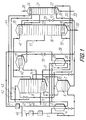
- a plant for practising the method according to the invention incorporates the following elements mounted in a line 1 according to the flow sheet: an air compressor 2, a device 3 for purifying air from moisture, carbon dioxide and hydrocarbons, an expander 4, a main heat exchanger 5 and a double rectifier 6 comprising a high-pressure column 7, a low-pressure column 8 and a main condenser 9.
- the columns 7 and 8 are communicated through a line 10 supplying liquid air enriched with oxygen and through a line 11 to supply liquid nitrogen.
- an oxygen outlet line 12 Connected to the column 8 are an oxygen outlet line 12, a nitrogen gas outlet line 13 and a gaseous argon fraction outlet line 14.
- the line 14 is connected with an additional condenser 15 which communicates with a rectifying column 16 through a liquid argon fraction supply line 17.
- the condenser 15 is installed at a height sufficient to provide a pressure in the place of the argon fraction inlet, which exceeds an argon-nitrogen fraction condensing pressure by a value of from 0.01 to 0.06 MPa, which makes it possible to overcome a hydraulic resistance of the upper part of the column 16.
- the column 16 is provided with an evaporator 18 and a condenser 19 and has a line 20 to withdraw a liquid fraction of high-boiling components.
- the column 16 communicates with a pure argon column 21 through a line 22 to supply the liquid argon-nitrogen fraction.
- the column 21 has an evaporator 23, a condenser 24, a pure argon outlet line 25 and a nitrogen fraction outlet line 26.
- the plant is provided with a circulation nitrogen cycle including a nitrogen circulation compressor 27, a circulating heat exchanger 28, connected by a compressed nitrogen gas line 29.
- a line 30 divided into a line 31 feeding nitrogen gas to the condenser 9, a line 32 to the evaporator 18 and a line 33 to the evaporator 23.
- the line 11 is connected with a line 34 to remove liquid nitrogen from the evaporator 18, connected to which is a line 35 to remove liquid nitrogen from the evaporator 23.
- To the line 10 of liquid air enriched with oxygen the condenser 15 is connected by a line 36 and a condenser 19 is connected by a line 37.
- the lines 36, 37 are provided with throttle valves 38, 39 respectively.
- the condensers 15 and 19 are connected to the column 8 respectively by lines 40, 41 to remove gaseous air enriched with oxygen.
- the condenser 24 is communicated with the line 11 by means of a liquid nitrogen feed line 42 provided with a throttle valve 43.
- a line 44 removing the nitrogen gas from the condenser 24 communicates with the line 13 connected to which through a nitrogen gas supply line 45 is the main heat exchanger 5.
- the heat exchanger 5 is provided with a line 46 to remove the nitrogen gas from the plant, to which line there is connected the compressor 27 with the aid of a line 47.
- the heat exchanger 28 through a nitrogen gas inlet line 48 is connected to the line 45, and through a nitrogen gas outlet line 49, to the line 46.
- the method according to the invention is realized in the following way. All air to be processed on being compressed in the compressor 2 and purified from moisture, carbon dioxide and hydrocarbons in the device 3 is fed through the line 1 to the expander 4 and the main heat exchanger 5. A part of air amounting to 60% of the volume of the air being processed is expanded in the expander 4 and the remaining air is cooled in the heat exchanger 5, throttled and on being mixed with the air from the expander 4 is fed into the column 7 for separation.
- liquid nitrogen containing 0.0001% by volume of oxygen which is divided into two parts: 28% of the volume of the air being processed is introduced through the line 11 into the column 8 as a reflux, whereas 2% of the volume of the air being processed is sent through the line 42 and the valve 43 into the condenser 24 and after evaporation is supplied through the line 44 to the line 45.
- liquid air enriched with oxygen up to 29-30% by volume is removed from the lower part of the column 7 .
- one flow amounting to 14% of the volume of the air being processed is throttled and fed through the line 10 to the column 8
- a second flow amounting to 28% of the volume of the air being processed through the line 36 and the valve 38 is supplied as a coolant into the condenser 15 and further after evaporation through the line 40 to the column 8
- a third flow in the amount of 28% of the volume of the air being processed is fed through the line 37 and the valve 39 into the condenser 19 and then after evaporation through the line 41 to the column 8.
- a low-pressure nitrogen gas which on being heated is passed through the line 49 to the line 46.
- the compressed cooled nitrogen gas through the line 30 is removed from the heat exchanger 28 through the line 30 and divided into three flows a first of which through the line 31 is fed to the condenser 9 to be liquefied.
- a second flow in an amount not exceeding 40% of the volume of the air being processed is directed through the line 32 to the evaporator 18 to deliver heat, from which the liquid nitrogen is removed through the line 34.
- a third flow through the line 33 is supplied into the evaporator 23 to deliver heat, liquefied and removed through the line 35.
- the liquid nitrogen flows through the lines 34 and 35 go to the line 11.
- a gaseous argon fraction in an amount of from 8 to 10% of the volume of the air being processed comprising from 10 to 12% by volume of argon, 0.5% by volume of nitrogen and sent to the condenser 15 to be liquefied and then through the line 17 for separation into the column 16 from the upper part of which an argon-nitrogen fraction containing 0.0005% by volume of oxygen is fed through the line 22 for final separation into the column 21.
- a liquid fraction of high-boiling components e.g. production oxygen in an amount of 10% of the volume of the air being processed.
- pure argon containing not more than 0.005% by volume of nitrogen and through the line 26, a nitrogen fraction containing not more than 8% by volume of argon.
- the rectifying column 16 mounts 240 trays, the argon-nitrogen fraction pressure at the outlet from the column is maintained equal to 0.11 MPa, the temperature head between the argon-nitrogen fraction and the boiling liquid air enriched with oxygen equals from 2 to 2.4 degrees.
- the pressure at the inlet of the liquid argon fraction to the column 16 amounts to 0.15 MPa.
- the argon recovery factor according to the method described is equal to 0.90.
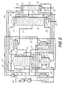
- Fig. 2 Shown in Fig. 2 is a plant for practising the method according to the invention differing from the foregoing version in that the gaseous argon fraction is liquefied by throttled liquid nitrogen.
- the condenser 15 communicates with the line 11 by means of a liquid nitrogen inlet line 50 provided with a throttle valve 51.
- the condenser 15 is connected with the line 13 with the aid of a nitrogen gas outlet line 52.
- the liquid nitrogen is taken from the line 11 through the line 50, throttled through the valve 51 and is further sent to the condenser 15 for liquefying the gaseous argon fraction. Removal of the nitrogen gas from the condenser 15 is carried out through the line 52.
- Fig. 3 Shown in Fig. 3 is a plant for practising a version of the method according to the invention, in which before being liquefied the argon fraction is enriched with low-boiling components, mixed with an evaporated fraction of high-boiling components, and the liquid nitrogen from the evaporators 18 and 23 is used as a coolant in the condenser 19.
- an additional rectifying column 53 Connected to the line 14 in the region between the column 8 and the condenser 19 is an additional rectifying column 53.
- the lower part of the column 53 communicates with the column 8 through a liquid argon fraction outlet line 54.
- the lines 34, 35 are connected through a line 55 having a throttle valve 56 to the condenser 19 which communicates through a nitrogen gas outlet line 57 to the line 44.
- a line 58 for feeding a liquid fraction of high-boiling components provided with a valve 59
- an evaporator 60 communicating with the aid of a line 61 for removing a gaseous fraction of high-boiling components to the line 14.
- the gaseous argon fraction through the line 14 is fed to the lower part of the additional rectifying column 53 to be enriched with low-boiling components, viz. nitrogen and argon, the oxygen content being not in excess of 3% by volume.
- the enriched fraction is liquefied in the condenser 15 and divided into two parts one of which in an amount not exceeding 1% of the volume of the air being processed through the line 17 is fed to the column 18 and a second is returned to the column 53 and further through the line 54 to the column 8.
- Flows of liquid nitrogen from the evaporators 18 and 23 through the lines 34, 35 respectively are fed to the line 55, throttled by the valve 56 and as a coolant are supplied to the condenser 19.
- the nitrogen gas evaporated in the condenser 19 is fed through the line 57 to the line 45.
- the fraction of high-boiling components through the line 58 is fed to the evaporator 60 and further through the line 61 joins the flow of the gaseous argon fraction through the line 14.
- the valve 59 is closed.
- the rectifying column 16 mounts 140 trays, the argon-nitrogen fraction pressure at the outlet from the column is 0.11 MPa, the temperature head between the argon-nitrogen fraction and the boiling liquid nitrogen amounts from 1.9 to 2.2 degrees.
- the pressure in the place of liquid argon fraction inlet to the column 16 is equal to 0.12 MPa.
- the argon recovery factor in accordance with the foregoing method equals 0.91.
- Shown in Fig. 4 is a plant for realizing a version of the method of the invention, in which the liquefied argon fraction is separated in the rectifying column 16 into a liquid fraction of high-boiling components containing 99.9% by volume of oxygen and two argon-nitrogen fractions.
- the evaporator 18 of the column 16 communicates with the condenser 19 by a liquid nitrogen feed line 62 having a throttle valve 63.
- the condenser 19 is connected by a nitrogen gas outlet line 64 with the line 45.
- the column 16 has outlet lines 65, 66 for gaseous argon-nitrogen fractions.
- the compressed cooled nitrogen is passed from the heat exchanger 28 through the line 30 and divided into two flows, a first of which in an amount of 35% of the volume of the air being processed is fed through the line 31 to the condenser 9 for liquefaction. A second flow amounting to 25% of the volume of the air being processed through the line 32 is fed to the evaporator 18 to deliver heat. From the evaporator 18 the liquid nitrogen is removed through the line 62 and the throttle valve 63 and fed as a coolant into the condenser 19 to be evaporated and through the line 64 to be sent to the nitrogen gas line 45.
- the content of argon in the argon-nitrogen fraction in the line 65 equals not more than 93% by volume and its amount does not exceed 1% of the volume of the air being processed.
- the content of argon in the argon-nitrogen fraction in the line 66 is equal to not less than 99.993% by volume.
- the liquid fraction of high-boiling components removed through the line 20 contains not more than 99.9% by volume of oxygen.
- the argon recovery factor according the method described above is equal to 0.91.
- a plant for practising the method according to the invention shown in Fig. 5 includes the following elements mounted in a line 1 according to the flow sheet: an air compressor 2, a device 3 for purifying air form moisture, carbon dioxide and hydrocarbons, an expander 4, a main heat exchanger 5.
- the line 1 is divided into a line 67 feeding air into an evaporator 18 and a line 68 feeding air into a double rectifier 6 comprising a high-pressure column 7, a low-pressure column 8 and a main condenser 9.
- the columns 7 and 8 are communicated through a line 10 supplying liquid air enriched with oxygen and through a line 11 supplying liquid nitrogen.
- Connected to the column 8 are an oxygen outlet line 12, a nitrogen gas outlet line 13 and a gaseous argon fraction outlet line 14.
- the line 14 is connected to an additional condenser 15 communicating with a rectifying column 16 through a liquid argon fraction feed line 17.
- the condenser 15 is installed at a height sufficient to provide a pressure in the place of inlet of the argon fraction exceeding an argon-nitrogen fraction condensing pressure by a value of from 0.01 to 0.06 MPa, which makes it possible to overcome a hydraulic resistance of the upper part of the column 16.
- the column 16 is provided with an evaporator 18 and a condenser 19 and has an outlet line 20 for a liquid fraction of high-boiling components.
- the column 16 is connected with a pure argon column 21 by a line 22 to supply the argon-nitrogen fraction.
- the column 21 has an evaporator 23, a condenser 24, an outlet line 25 of pure argon and a nitrogen fraction outlet line 26.
- the plant is provided with a nitrogen circulation cycle including a nitrogen circulation compressor 27, a criculating heat exchanger 28 connected by a compressed nitrogen gas line 29. Connected to an outlet of the heat exchanger 28 is a line 31 feeding nitrogen gas to the condenser 9. Connected to the line 11 is a line 35 to remove liquid nitrogen from the evaporator 23. To the line 10 supplying liquid air enriched with oxygen there is connected the condenser 15 with the aid of a line 36 having a throttle valve 38. The condenser 24 is connected to the line 11 with the aid of a liquid nitrogen feed line 42 and a throttle valve 43.
- a line 44 removing the nitrogen gas from the condenser 24 communicates with the line 13 connected to which through a nitrogen gas feed line 45 is the main heat exchanger 5.
- the heat exchanger 5 is provided with a line 46 to remove the nitrogen gas from the plant, to which line there is connected the nitrogen circulating compressor 27 with the aid of a line 47.
- the heat exchanger 28 through a nitrogen gas inlet line 48 is connected to the line 45 and through a nitrogen gas outlet line 49, to the line 46.
- the condenser 15 is connected to the column 8 by an outlet line 40 of air gas enriched with oxygen and the condenser 19, by an air gas outlet line 69.
- the evaporator 18 is connected with the condenser 19 by a line 70 having a throttle valve 71.
- the column 7 communicates with the condenser 9 through a nitrogen gas feed line 72. Connected to the line 72 is a line 73 feeding nitrogen gas to the evaporator 23.
- the method according to the invention is realized in the following way. All air to be processed on being compressed in the compressor 2 and purified from moisture, carbon dioxide and hydrocarbons in the device 3 is fed through the line 1 to the expander 4 and the main heat exchanger 5. A greater part of air amounting to 60% of the volume of the air being processed is expanded in the expander 4 and the remainder of the air amounting to 40% of the volume of the air being processed is cooled in the main heat exchanger 5, throttled, joined with the flow downstream from the expander 4 and divided into two parts.
- a first part in an amount of 70% of the volume of the air being processed is fed through the line 68 to the column 7.
- the remaining part of the air is supplied through the line 67 to the evaporator 18.
- From the upper part of the column 7 there is extracted liquid nitrogen containing 0.0001% by volume of oxygen, which is divided into two parts.
- a first one in an amount of 19% of the volume of the air being processed through the line 11 is introduced as a reflux into the column 8, whereas a second part in an amount of 2% of the volume of the air being processed is sent through the line 42 and the valve 43 to the condenser 24 and after evaporation is fed through the line 44 to the line 45.
- From the lower part of the column 7 there is taken liquid air enriched with oxygen up to 29-30% by volume and divided into two flows.
- a first flow in an amount of 21% of the volume of the air being processed is throttled in the line 10 and fed to the column 8, and a second flow in an amount of 28% of the volume of the air being processed is fed through the line 36 and the valve 38 to the condenser 15 and further after evaporation through the line 40 to the column 8.
- the nitrogen gas is removed and divided into two flows one of which in an amount not in excess of 80% of the volume of the air being processed is discharged from the plant through the line 46, another in an amount of 30% of the volume of the air being processed through the line 47 is fed to the nitrogen circulation compressor 27 to be compressed to a pressure of from 0.75 to 0.8 MPa.
- the compressed nitrogen through the line 29 is supplied to the heat exchanger 28.
- a low-pressure nitrogen gas which on being heated is fed to the line 46 through the line 49.
- the compressed cooled nitrogen gas is removed from the heat exchanger 28 through the line 31 to the line 72 and is fed to the condenser 9 for liquefaction.
- the nitrogen gas is removed and fed through the line 73 to the evaporator 23 to deliver heat, wherefrom on being liquefied it is passed through the line 35 to the line 11.
- a gaseous argon fraction containing from 10 to 12% by volume of argon, 0.3% by volume of nitrogen, in an amount of from 7 to 9% of the volume of the air being processed and is fed to the condenser 15 for liquefaction and further through the line 17 to the column 16 for separation.
- the air gas through the line 67 is fed to the evaporator 18 to deliver heat.
- the liquid air through the line 70 and the valve 71 is fed to the condenser 19 to be used as a coolant.
- the evaporated air gas through the line 69 is sent to the column 8 for separation.
- an argon-nitrogen fraction containing 0.0005% by volume of oxygen is fed through the line 22 to the column 21 for final separation.
- a liquie fraction of high-boiling components viz. production oxygen in an amount of 10% of the volume of athe air being processed.
- production argon containing not more than 0.005% by volume of nitrogen
- a nitrogen fraction containing not more than 8% by volume of argon.
- the rectifying column 16 mounts 250 trays, the argon-nitrogen fraction pressure at the outlet from the column equals 0.11 MPa, the temperature head between the argon-nitrogen fraction and the boiling liquid air ranges from 2 to 2.4 degrees. The pressure in the place of the inlet of the liquid argon fraction to the column 16 amounts to 0.155 MPa.
- the argon recovery factor according to the described method is equal to 0.9.
- the invention will find application in chemical industry and mechanical engineering.
Landscapes
- Engineering & Computer Science (AREA)
- Physics & Mathematics (AREA)
- Mechanical Engineering (AREA)
- Thermal Sciences (AREA)
- General Engineering & Computer Science (AREA)
- Separation By Low-Temperature Treatments (AREA)
Priority Applications (2)
| Application Number | Priority Date | Filing Date | Title |
|---|---|---|---|
| US07/701,806 US5207066A (en) | 1991-10-22 | 1991-05-17 | Method of air separation |
| EP91309755A EP0538520A1 (fr) | 1991-10-22 | 1991-10-22 | Procédé de séparation d'air |
Applications Claiming Priority (1)
| Application Number | Priority Date | Filing Date | Title |
|---|---|---|---|
| EP91309755A EP0538520A1 (fr) | 1991-10-22 | 1991-10-22 | Procédé de séparation d'air |
Publications (1)
| Publication Number | Publication Date |
|---|---|
| EP0538520A1 true EP0538520A1 (fr) | 1993-04-28 |
Family
ID=8208431
Family Applications (1)
| Application Number | Title | Priority Date | Filing Date |
|---|---|---|---|
| EP91309755A Ceased EP0538520A1 (fr) | 1991-10-22 | 1991-10-22 | Procédé de séparation d'air |
Country Status (2)
| Country | Link |
|---|---|
| US (1) | US5207066A (fr) |
| EP (1) | EP0538520A1 (fr) |
Cited By (6)
| Publication number | Priority date | Publication date | Assignee | Title |
|---|---|---|---|---|
| EP0752565A3 (fr) * | 1995-07-06 | 1998-01-28 | The BOC Group plc | Production d'argon |
| EP0947791A3 (fr) * | 1998-04-02 | 1999-12-22 | Praxair Technology, Inc. | Système cryogénique pour la production d'argon avec une colonne de strippage thermiquement integrée |
| WO2000058675A1 (fr) * | 1999-03-29 | 2000-10-05 | L'air Liquide Societe Anonyme Pour L'etude Et L'exploitation Des Procedes Georges Claude | Procede et installation de production d'argon par distillation cryogenique |
| EP1162424A3 (fr) * | 2000-06-10 | 2002-01-09 | Messer AGS GmbH | Procédé et installation de production d'argon |
| EP1162422A3 (fr) * | 2000-06-10 | 2002-01-09 | Messer AGS GmbH | Procédé et installation de production d'argon |
| EP3812675A1 (fr) * | 2019-10-24 | 2021-04-28 | L'air Liquide, Societe Anonyme Pour L'etude Et L'exploitation Des Procedes Georges Claude | Procédé et appareil de séparation d'air par distillation cryogénique |
Families Citing this family (10)
| Publication number | Priority date | Publication date | Assignee | Title |
|---|---|---|---|---|
| DE4317916A1 (de) * | 1993-05-28 | 1994-12-01 | Linde Ag | Verfahren und Vorrichtung zur Gewinnung von Argon |
| CA2142317A1 (fr) * | 1994-02-24 | 1995-08-25 | Anton Moll | Methode et appareil pour la recuperation d'argon pur |
| DE69631467T2 (de) * | 1995-06-20 | 2004-12-02 | Nippon Sanso Corp. | Verfahren und vorrichtung zur abtrennung von argon |
| RU2129904C1 (ru) * | 1998-04-21 | 1999-05-10 | Савинов Михаил Юрьевич | Способ получения ксенонового концентрата на воздухоразделительных установках |
| US6438994B1 (en) * | 2001-09-27 | 2002-08-27 | Praxair Technology, Inc. | Method for providing refrigeration using a turboexpander cycle |
| DE10228111A1 (de) * | 2002-06-24 | 2004-01-15 | Linde Ag | Luftzerlegungsverfahren und -anlage mit Mischsäule und Krypton-Xenon-Gewinnung |
| USD594348S1 (en) | 2008-06-24 | 2009-06-16 | Colgate-Palmolive Company | Multiple product package |
| TWI401189B (zh) * | 2009-09-18 | 2013-07-11 | Colgate Palmolive Co | 用於產品之展示包裝盒 |
| FR3108970B1 (fr) * | 2020-04-02 | 2022-10-28 | Air Liquide | Procédé de démarrage d’une colonne de séparation d’argon d’un appareil de séparation d’air par distillation cryogénique et unité pour mise en œuvre du procédé |
| JP7133735B1 (ja) * | 2022-03-07 | 2022-09-08 | レール・リキード-ソシエテ・アノニム・プール・レテュード・エ・レクスプロワタシオン・デ・プロセデ・ジョルジュ・クロード | 空気分離装置 |
Citations (2)
| Publication number | Priority date | Publication date | Assignee | Title |
|---|---|---|---|---|
| DE930033C (de) * | 1953-04-12 | 1956-03-08 | Adolf Messer G M B H | Verfahren zur Argonerzeugung |
| FR2305701A1 (fr) * | 1975-03-26 | 1976-10-22 | Siad | Procede et appareil de recuperation d'argon dans un processus de fractionnement de l'air |
Family Cites Families (5)
| Publication number | Priority date | Publication date | Assignee | Title |
|---|---|---|---|---|
| JPS59150286A (ja) * | 1983-02-15 | 1984-08-28 | 日本酸素株式会社 | アルゴンの製造方法 |
| US4715873A (en) * | 1986-04-24 | 1987-12-29 | Air Products And Chemicals, Inc. | Liquefied gases using an air recycle liquefier |
| US4705548A (en) * | 1986-04-25 | 1987-11-10 | Air Products And Chemicals, Inc. | Liquid products using an air and a nitrogen recycle liquefier |
| DE3840506A1 (de) * | 1988-12-01 | 1990-06-07 | Linde Ag | Verfahren und vorrichtung zur luftzerlegung |
| CN1025067C (zh) * | 1989-02-23 | 1994-06-15 | 琳德股份公司 | 精馏分离空气的方法及装置 |
-
1991
- 1991-05-17 US US07/701,806 patent/US5207066A/en not_active Expired - Fee Related
- 1991-10-22 EP EP91309755A patent/EP0538520A1/fr not_active Ceased
Patent Citations (2)
| Publication number | Priority date | Publication date | Assignee | Title |
|---|---|---|---|---|
| DE930033C (de) * | 1953-04-12 | 1956-03-08 | Adolf Messer G M B H | Verfahren zur Argonerzeugung |
| FR2305701A1 (fr) * | 1975-03-26 | 1976-10-22 | Siad | Procede et appareil de recuperation d'argon dans un processus de fractionnement de l'air |
Non-Patent Citations (1)
| Title |
|---|
| PATENT ABSTRACTS OF JAPAN vol. 3, no. 147 (C-66)5 December 1979 & JP-A-54 126 672 ( HITACHI SEISAKUSHO ) 10 February 1979 * |
Cited By (8)
| Publication number | Priority date | Publication date | Assignee | Title |
|---|---|---|---|---|
| EP0752565A3 (fr) * | 1995-07-06 | 1998-01-28 | The BOC Group plc | Production d'argon |
| EP0947791A3 (fr) * | 1998-04-02 | 1999-12-22 | Praxair Technology, Inc. | Système cryogénique pour la production d'argon avec une colonne de strippage thermiquement integrée |
| WO2000058675A1 (fr) * | 1999-03-29 | 2000-10-05 | L'air Liquide Societe Anonyme Pour L'etude Et L'exploitation Des Procedes Georges Claude | Procede et installation de production d'argon par distillation cryogenique |
| FR2791762A1 (fr) * | 1999-03-29 | 2000-10-06 | Air Liquide | Procede et installation de production d'argon par distillation cryogenique |
| US6574988B1 (en) | 1999-03-29 | 2003-06-10 | L'air Liquide Societe Anonyme A Directoire Et Conseil De Surveillance Pour L'etude Et L'exploitation Des Procedes Georges Claude | Process and plant for producing argon by cryogenic distillation |
| EP1162424A3 (fr) * | 2000-06-10 | 2002-01-09 | Messer AGS GmbH | Procédé et installation de production d'argon |
| EP1162422A3 (fr) * | 2000-06-10 | 2002-01-09 | Messer AGS GmbH | Procédé et installation de production d'argon |
| EP3812675A1 (fr) * | 2019-10-24 | 2021-04-28 | L'air Liquide, Societe Anonyme Pour L'etude Et L'exploitation Des Procedes Georges Claude | Procédé et appareil de séparation d'air par distillation cryogénique |
Also Published As
| Publication number | Publication date |
|---|---|
| US5207066A (en) | 1993-05-04 |
Similar Documents
| Publication | Publication Date | Title |
|---|---|---|
| US5207066A (en) | Method of air separation | |
| US4704148A (en) | Cycle to produce low purity oxygen | |
| EP0425738B1 (fr) | Procédé de production de l'azote à haute pression en utilisant la fonction d'un rebouilleur-condenseur divisé | |
| US4843828A (en) | Liquid-vapor contact method and apparatus | |
| US3210951A (en) | Method for low temperature separation of gaseous mixtures | |
| US3370435A (en) | Process for separating gaseous mixtures | |
| EP0194795B1 (fr) | Epuration de dioxyde de carbone pour son utilisation dans la brasserie | |
| EP0173168A2 (fr) | Procédé pour la production d'oxygène de très haute pureté | |
| EP0633438A1 (fr) | Séparation de l'air | |
| EP2963368B1 (fr) | Procédé de séparation d'air et appareil de séparation d'air | |
| DE69320116T2 (de) | Lufttrennung | |
| CN1056566A (zh) | 空气分离 | |
| NO169977B (no) | Fremgangsmaate for separering av luft ved kryogen destillasjon | |
| JPH06210162A (ja) | 熱的に統合されたアルゴンカラムを有する極低温精留系 | |
| JP2776461B2 (ja) | 超高純度酸素を製造する低温蒸留による空気分別方法 | |
| EP0222026B1 (fr) | Procédé de préparation d'un concentré crypton-xénon exempt d'oxygène | |
| KR900007209B1 (ko) | 보조 컬럼을 추진력으로 하는 혼성 질소 발생기 | |
| US2040116A (en) | Method for the separation and recovery of krypton and xenon from gaseous mixtures containing them | |
| CN1396427A (zh) | 低温分离空气的三塔系统 | |
| US5058387A (en) | Process to ultrapurify liquid nitrogen imported as back-up for nitrogen generating plants | |
| EP0283213A2 (fr) | Procédé de récupération de l'argon | |
| JP3929799B2 (ja) | 超高純度酸素の製造方法及び製造装置 | |
| JPH07218122A (ja) | 空気を分離するための方法および装置 | |
| US4530708A (en) | Air separation method and apparatus therefor | |
| CA1280360C (fr) | Procede de separation de l'air avec recuperation des gaz residuaires pour laproduction de l'azote et de l'oxygene |
Legal Events
| Date | Code | Title | Description |
|---|---|---|---|
| PUAI | Public reference made under article 153(3) epc to a published international application that has entered the european phase |
Free format text: ORIGINAL CODE: 0009012 |
|
| AK | Designated contracting states |
Kind code of ref document: A1 Designated state(s): DE FR GB |
|
| 17P | Request for examination filed |
Effective date: 19930714 |
|
| 17Q | First examination report despatched |
Effective date: 19940225 |
|
| STAA | Information on the status of an ep patent application or granted ep patent |
Free format text: STATUS: THE APPLICATION HAS BEEN REFUSED |
|
| 18R | Application refused |
Effective date: 19950611 |