EP3813152A1 - Module de batterie secondaire - Google Patents
Module de batterie secondaire Download PDFInfo
- Publication number
- EP3813152A1 EP3813152A1 EP19822527.8A EP19822527A EP3813152A1 EP 3813152 A1 EP3813152 A1 EP 3813152A1 EP 19822527 A EP19822527 A EP 19822527A EP 3813152 A1 EP3813152 A1 EP 3813152A1
- Authority
- EP
- European Patent Office
- Prior art keywords
- bus bar
- module
- battery
- secondary battery
- block
- Prior art date
- Legal status (The legal status is an assumption and is not a legal conclusion. Google has not performed a legal analysis and makes no representation as to the accuracy of the status listed.)
- Pending
Links
Images



Classifications
-
- H—ELECTRICITY
- H01—ELECTRIC ELEMENTS
- H01M—PROCESSES OR MEANS, e.g. BATTERIES, FOR THE DIRECT CONVERSION OF CHEMICAL ENERGY INTO ELECTRICAL ENERGY
- H01M50/00—Constructional details or processes of manufacture of the non-active parts of electrochemical cells other than fuel cells, e.g. hybrid cells
- H01M50/50—Current conducting connections for cells or batteries
- H01M50/502—Interconnectors for connecting terminals of adjacent batteries; Interconnectors for connecting cells outside a battery casing
-
- H—ELECTRICITY
- H01—ELECTRIC ELEMENTS
- H01M—PROCESSES OR MEANS, e.g. BATTERIES, FOR THE DIRECT CONVERSION OF CHEMICAL ENERGY INTO ELECTRICAL ENERGY
- H01M50/00—Constructional details or processes of manufacture of the non-active parts of electrochemical cells other than fuel cells, e.g. hybrid cells
- H01M50/20—Mountings; Secondary casings or frames; Racks, modules or packs; Suspension devices; Shock absorbers; Transport or carrying devices; Holders
- H01M50/204—Racks, modules or packs for multiple batteries or multiple cells
-
- H—ELECTRICITY
- H01—ELECTRIC ELEMENTS
- H01M—PROCESSES OR MEANS, e.g. BATTERIES, FOR THE DIRECT CONVERSION OF CHEMICAL ENERGY INTO ELECTRICAL ENERGY
- H01M50/00—Constructional details or processes of manufacture of the non-active parts of electrochemical cells other than fuel cells, e.g. hybrid cells
- H01M50/20—Mountings; Secondary casings or frames; Racks, modules or packs; Suspension devices; Shock absorbers; Transport or carrying devices; Holders
- H01M50/204—Racks, modules or packs for multiple batteries or multiple cells
- H01M50/207—Racks, modules or packs for multiple batteries or multiple cells characterised by their shape
- H01M50/209—Racks, modules or packs for multiple batteries or multiple cells characterised by their shape adapted for prismatic or rectangular cells
-
- H—ELECTRICITY
- H01—ELECTRIC ELEMENTS
- H01M—PROCESSES OR MEANS, e.g. BATTERIES, FOR THE DIRECT CONVERSION OF CHEMICAL ENERGY INTO ELECTRICAL ENERGY
- H01M50/00—Constructional details or processes of manufacture of the non-active parts of electrochemical cells other than fuel cells, e.g. hybrid cells
- H01M50/20—Mountings; Secondary casings or frames; Racks, modules or packs; Suspension devices; Shock absorbers; Transport or carrying devices; Holders
- H01M50/233—Mountings; Secondary casings or frames; Racks, modules or packs; Suspension devices; Shock absorbers; Transport or carrying devices; Holders characterised by physical properties of casings or racks, e.g. dimensions
- H01M50/242—Mountings; Secondary casings or frames; Racks, modules or packs; Suspension devices; Shock absorbers; Transport or carrying devices; Holders characterised by physical properties of casings or racks, e.g. dimensions adapted for protecting batteries against vibrations, collision impact or swelling
-
- H—ELECTRICITY
- H01—ELECTRIC ELEMENTS
- H01M—PROCESSES OR MEANS, e.g. BATTERIES, FOR THE DIRECT CONVERSION OF CHEMICAL ENERGY INTO ELECTRICAL ENERGY
- H01M50/00—Constructional details or processes of manufacture of the non-active parts of electrochemical cells other than fuel cells, e.g. hybrid cells
- H01M50/20—Mountings; Secondary casings or frames; Racks, modules or packs; Suspension devices; Shock absorbers; Transport or carrying devices; Holders
- H01M50/244—Secondary casings; Racks; Suspension devices; Carrying devices; Holders characterised by their mounting method
-
- H—ELECTRICITY
- H01—ELECTRIC ELEMENTS
- H01M—PROCESSES OR MEANS, e.g. BATTERIES, FOR THE DIRECT CONVERSION OF CHEMICAL ENERGY INTO ELECTRICAL ENERGY
- H01M50/00—Constructional details or processes of manufacture of the non-active parts of electrochemical cells other than fuel cells, e.g. hybrid cells
- H01M50/20—Mountings; Secondary casings or frames; Racks, modules or packs; Suspension devices; Shock absorbers; Transport or carrying devices; Holders
- H01M50/258—Modular batteries; Casings provided with means for assembling
-
- H—ELECTRICITY
- H01—ELECTRIC ELEMENTS
- H01M—PROCESSES OR MEANS, e.g. BATTERIES, FOR THE DIRECT CONVERSION OF CHEMICAL ENERGY INTO ELECTRICAL ENERGY
- H01M50/00—Constructional details or processes of manufacture of the non-active parts of electrochemical cells other than fuel cells, e.g. hybrid cells
- H01M50/20—Mountings; Secondary casings or frames; Racks, modules or packs; Suspension devices; Shock absorbers; Transport or carrying devices; Holders
- H01M50/262—Mountings; Secondary casings or frames; Racks, modules or packs; Suspension devices; Shock absorbers; Transport or carrying devices; Holders with fastening means, e.g. locks
-
- H—ELECTRICITY
- H01—ELECTRIC ELEMENTS
- H01M—PROCESSES OR MEANS, e.g. BATTERIES, FOR THE DIRECT CONVERSION OF CHEMICAL ENERGY INTO ELECTRICAL ENERGY
- H01M50/00—Constructional details or processes of manufacture of the non-active parts of electrochemical cells other than fuel cells, e.g. hybrid cells
- H01M50/20—Mountings; Secondary casings or frames; Racks, modules or packs; Suspension devices; Shock absorbers; Transport or carrying devices; Holders
- H01M50/262—Mountings; Secondary casings or frames; Racks, modules or packs; Suspension devices; Shock absorbers; Transport or carrying devices; Holders with fastening means, e.g. locks
- H01M50/264—Mountings; Secondary casings or frames; Racks, modules or packs; Suspension devices; Shock absorbers; Transport or carrying devices; Holders with fastening means, e.g. locks for cells or batteries, e.g. straps, tie rods or peripheral frames
-
- H—ELECTRICITY
- H01—ELECTRIC ELEMENTS
- H01M—PROCESSES OR MEANS, e.g. BATTERIES, FOR THE DIRECT CONVERSION OF CHEMICAL ENERGY INTO ELECTRICAL ENERGY
- H01M50/00—Constructional details or processes of manufacture of the non-active parts of electrochemical cells other than fuel cells, e.g. hybrid cells
- H01M50/20—Mountings; Secondary casings or frames; Racks, modules or packs; Suspension devices; Shock absorbers; Transport or carrying devices; Holders
- H01M50/289—Mountings; Secondary casings or frames; Racks, modules or packs; Suspension devices; Shock absorbers; Transport or carrying devices; Holders characterised by spacing elements or positioning means within frames, racks or packs
- H01M50/291—Mountings; Secondary casings or frames; Racks, modules or packs; Suspension devices; Shock absorbers; Transport or carrying devices; Holders characterised by spacing elements or positioning means within frames, racks or packs characterised by their shape
-
- H—ELECTRICITY
- H01—ELECTRIC ELEMENTS
- H01M—PROCESSES OR MEANS, e.g. BATTERIES, FOR THE DIRECT CONVERSION OF CHEMICAL ENERGY INTO ELECTRICAL ENERGY
- H01M50/00—Constructional details or processes of manufacture of the non-active parts of electrochemical cells other than fuel cells, e.g. hybrid cells
- H01M50/20—Mountings; Secondary casings or frames; Racks, modules or packs; Suspension devices; Shock absorbers; Transport or carrying devices; Holders
- H01M50/296—Mountings; Secondary casings or frames; Racks, modules or packs; Suspension devices; Shock absorbers; Transport or carrying devices; Holders characterised by terminals of battery packs
-
- H—ELECTRICITY
- H01—ELECTRIC ELEMENTS
- H01M—PROCESSES OR MEANS, e.g. BATTERIES, FOR THE DIRECT CONVERSION OF CHEMICAL ENERGY INTO ELECTRICAL ENERGY
- H01M50/00—Constructional details or processes of manufacture of the non-active parts of electrochemical cells other than fuel cells, e.g. hybrid cells
- H01M50/20—Mountings; Secondary casings or frames; Racks, modules or packs; Suspension devices; Shock absorbers; Transport or carrying devices; Holders
- H01M50/298—Mountings; Secondary casings or frames; Racks, modules or packs; Suspension devices; Shock absorbers; Transport or carrying devices; Holders characterised by the wiring of battery packs
-
- H—ELECTRICITY
- H01—ELECTRIC ELEMENTS
- H01M—PROCESSES OR MEANS, e.g. BATTERIES, FOR THE DIRECT CONVERSION OF CHEMICAL ENERGY INTO ELECTRICAL ENERGY
- H01M50/00—Constructional details or processes of manufacture of the non-active parts of electrochemical cells other than fuel cells, e.g. hybrid cells
- H01M50/50—Current conducting connections for cells or batteries
-
- H—ELECTRICITY
- H01—ELECTRIC ELEMENTS
- H01M—PROCESSES OR MEANS, e.g. BATTERIES, FOR THE DIRECT CONVERSION OF CHEMICAL ENERGY INTO ELECTRICAL ENERGY
- H01M50/00—Constructional details or processes of manufacture of the non-active parts of electrochemical cells other than fuel cells, e.g. hybrid cells
- H01M50/50—Current conducting connections for cells or batteries
- H01M50/502—Interconnectors for connecting terminals of adjacent batteries; Interconnectors for connecting cells outside a battery casing
- H01M50/503—Interconnectors for connecting terminals of adjacent batteries; Interconnectors for connecting cells outside a battery casing characterised by the shape of the interconnectors
-
- H—ELECTRICITY
- H01—ELECTRIC ELEMENTS
- H01M—PROCESSES OR MEANS, e.g. BATTERIES, FOR THE DIRECT CONVERSION OF CHEMICAL ENERGY INTO ELECTRICAL ENERGY
- H01M50/00—Constructional details or processes of manufacture of the non-active parts of electrochemical cells other than fuel cells, e.g. hybrid cells
- H01M50/50—Current conducting connections for cells or batteries
- H01M50/502—Interconnectors for connecting terminals of adjacent batteries; Interconnectors for connecting cells outside a battery casing
- H01M50/505—Interconnectors for connecting terminals of adjacent batteries; Interconnectors for connecting cells outside a battery casing comprising a single busbar
-
- H—ELECTRICITY
- H01—ELECTRIC ELEMENTS
- H01M—PROCESSES OR MEANS, e.g. BATTERIES, FOR THE DIRECT CONVERSION OF CHEMICAL ENERGY INTO ELECTRICAL ENERGY
- H01M50/00—Constructional details or processes of manufacture of the non-active parts of electrochemical cells other than fuel cells, e.g. hybrid cells
- H01M50/50—Current conducting connections for cells or batteries
- H01M50/502—Interconnectors for connecting terminals of adjacent batteries; Interconnectors for connecting cells outside a battery casing
- H01M50/514—Methods for interconnecting adjacent batteries or cells
- H01M50/516—Methods for interconnecting adjacent batteries or cells by welding, soldering or brazing
-
- H—ELECTRICITY
- H01—ELECTRIC ELEMENTS
- H01M—PROCESSES OR MEANS, e.g. BATTERIES, FOR THE DIRECT CONVERSION OF CHEMICAL ENERGY INTO ELECTRICAL ENERGY
- H01M50/00—Constructional details or processes of manufacture of the non-active parts of electrochemical cells other than fuel cells, e.g. hybrid cells
- H01M50/50—Current conducting connections for cells or batteries
- H01M50/502—Interconnectors for connecting terminals of adjacent batteries; Interconnectors for connecting cells outside a battery casing
- H01M50/521—Interconnectors for connecting terminals of adjacent batteries; Interconnectors for connecting cells outside a battery casing characterised by the material
- H01M50/522—Inorganic material
-
- H—ELECTRICITY
- H01—ELECTRIC ELEMENTS
- H01M—PROCESSES OR MEANS, e.g. BATTERIES, FOR THE DIRECT CONVERSION OF CHEMICAL ENERGY INTO ELECTRICAL ENERGY
- H01M50/00—Constructional details or processes of manufacture of the non-active parts of electrochemical cells other than fuel cells, e.g. hybrid cells
- H01M50/50—Current conducting connections for cells or batteries
- H01M50/528—Fixed electrical connections, i.e. not intended for disconnection
-
- H—ELECTRICITY
- H01—ELECTRIC ELEMENTS
- H01M—PROCESSES OR MEANS, e.g. BATTERIES, FOR THE DIRECT CONVERSION OF CHEMICAL ENERGY INTO ELECTRICAL ENERGY
- H01M50/00—Constructional details or processes of manufacture of the non-active parts of electrochemical cells other than fuel cells, e.g. hybrid cells
- H01M50/50—Current conducting connections for cells or batteries
- H01M50/543—Terminals
-
- H—ELECTRICITY
- H01—ELECTRIC ELEMENTS
- H01M—PROCESSES OR MEANS, e.g. BATTERIES, FOR THE DIRECT CONVERSION OF CHEMICAL ENERGY INTO ELECTRICAL ENERGY
- H01M50/00—Constructional details or processes of manufacture of the non-active parts of electrochemical cells other than fuel cells, e.g. hybrid cells
- H01M50/50—Current conducting connections for cells or batteries
- H01M50/572—Means for preventing undesired use or discharge
- H01M50/574—Devices or arrangements for the interruption of current
- H01M50/583—Devices or arrangements for the interruption of current in response to current, e.g. fuses
-
- H—ELECTRICITY
- H01—ELECTRIC ELEMENTS
- H01M—PROCESSES OR MEANS, e.g. BATTERIES, FOR THE DIRECT CONVERSION OF CHEMICAL ENERGY INTO ELECTRICAL ENERGY
- H01M2200/00—Safety devices for primary or secondary batteries
- H01M2200/10—Temperature sensitive devices
- H01M2200/103—Fuse
-
- Y—GENERAL TAGGING OF NEW TECHNOLOGICAL DEVELOPMENTS; GENERAL TAGGING OF CROSS-SECTIONAL TECHNOLOGIES SPANNING OVER SEVERAL SECTIONS OF THE IPC; TECHNICAL SUBJECTS COVERED BY FORMER USPC CROSS-REFERENCE ART COLLECTIONS [XRACs] AND DIGESTS
- Y02—TECHNOLOGIES OR APPLICATIONS FOR MITIGATION OR ADAPTATION AGAINST CLIMATE CHANGE
- Y02E—REDUCTION OF GREENHOUSE GAS [GHG] EMISSIONS, RELATED TO ENERGY GENERATION, TRANSMISSION OR DISTRIBUTION
- Y02E60/00—Enabling technologies; Technologies with a potential or indirect contribution to GHG emissions mitigation
- Y02E60/10—Energy storage using batteries
Definitions
- the present invention relates to secondary battery modules.
- a secondary battery module obtained by stacking a plurality of battery cells is known as a technique in such a field.
- the battery cells are electrically connected by bus bars.
- a bus bar with a so-called fuse function is adopted by providing one of the plurality of bus bars with a fuse portion.
- Patent Literature 1 discloses a secondary battery module having a bus bar with a fuse function that has a small cross-section portion (i.e., a fuse portion) with a cross-section smaller than those of the other portions.
- a fuse portion When an abnormal overcurrent flows through the bus bar, the fuse portion is allowed to fuse through generation of heat, thereby protecting the battery cells.
- Patent Literature 1 JP 2013-73929 A
- the present invention has been made to solve such a technical problem, and it is an object of the present invention to provide a secondary battery module in which stress applied to a fuse portion can be reduced and thus breakage of the fuse portion can be suppressed.
- a secondary battery module is a secondary battery module with a plurality of battery blocks each obtained by stacking a plurality of battery cells, including a holding member adapted to hold the plurality of the battery blocks, the holding member including a pair of opposed end plates, a pair of opposed side plates, and a section plate arranged between the adjacent battery blocks to partition the battery blocks; and an inter-block bus bar provided across the section plate and adapted to electrically connect the adjacent battery blocks, in which the inter-block bus bar has a fuse portion.
- a secondary battery module is a secondary battery module with at least one battery block obtained by stacking a plurality of battery cells, including a holding member adapted to hold the battery block, the holding member including a pair of opposed end plates and a pair of opposed side plates; and a plurality of bus bars at ends of the module, each of the plurality of bus bars at the ends of the module having one end electrically connected to the battery block and having another end extending toward one of the end plates or one of the side plates and electrically connected to an external connection terminal of the module, in which at least one of the plurality of bus bars at the ends of the module has a fuse portion.
- stress applied to a fuse portion can be reduced, and thus breakage of the fuse portion can be suppressed.
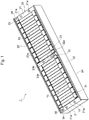
- Fig. 1 is a perspective view of a secondary battery module according to a first embodiment.
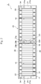
- Fig. 2 is a plan view of the secondary battery module according to the first embodiment.
- the secondary battery module 1 of the present embodiment mainly includes two battery blocks 10 each obtained by stacking a plurality of battery cells 11 in a given direction, and a holding member 20 adapted to hold the two battery blocks 10 arranged in series in the stacked direction of the battery cells 11.
- Each battery block 10 is formed by stacking a plurality of (herein, 17) flat rectangular battery cells 11 in the stacked direction with interposed therebetween cell holders (not illustrated) each made of an insulating resin material.
- Fig. 3 is a perspective view of each battery cell.
- the battery cell 11 includes a cell can 12 and a cell lid 13.
- the cell can 12 has a so-called closed-bottomed rectangular tube shape, and includes a rectangular can bottom portion 12a; and a pair of opposed wide side face portions 12b and a pair of opposed narrow side face portions 12c arranged in upright position on the four sides of the can bottom portion 12a, the pair of wide side face portions 12b having relatively large areas, and the pair of narrow side face portions 12c having relatively small areas.
- the cell can 12 houses a flat wound electrode group and an electrolytic solution, for example.
- the cell lid 13 is approximately rectangular in shape, and is joined to the cell can 12 so as to cover the opening of the cell can 12. Examples of the joining method include laser welding.
- the cell lid 13 has a positive electrode terminal 14 and a negative electrode terminal 15 each provided in a protruding manner. Each of the positive electrode terminal 14 and the negative electrode terminal 15 has an end that is formed flat so as to be easily joined to an inter-cell bus bar 31, an inter-block bus bar 32, or a bus bar 33 at an end of the module (described below) by laser welding.
- the cell lid 13 is provided with a gas exhaust valve 16.
- the gas exhaust valve 16 is opened to discharge the gas in the battery cell 11. Accordingly, the pressure in the battery cell 11 can be reduced, and thus the safety of the battery cell 11 can be secured.
- the cell lid 13 is provided with a liquid inlet plug 17 for closing a liquid inlet for an electrolytic solution.
- the liquid inlet plug 17 is joined to the cell lid 13 by laser welding after the battery cell 11 is filled with an electrolytic solution via the liquid inlet, for example.
- the plurality of battery cells 11 each having the aforementioned structure are stacked while being alternately inverted by 180° such that the positive electrode terminal 14 of one of the mutually adjacent battery cells 11 is adjacent to the negative electrode terminal 15 of the other battery cell 11.
- the positive electrode terminal 14 of one of the mutually adjacent battery cells 11 is electrically connected to the negative electrode terminal 15 of the other battery cell 11 by an inter-cell bus bar 31.
- the inter-cell bus bar 31 is formed flat using an aluminum material, for example, and is joined to the positive electrode terminal 14 and the negative electrode terminal 15 by laser welding while being placed on the positive electrode terminal 14 and the negative electrode terminal 15 so as to cover them.
- the holding member 20 is formed in the shape of a box having an open upper face, for example, and includes a rectangular bottom plate portion 24; a pair of end plates 21 and a pair of side plates 22 arranged in upright position on the four sides of the bottom plate portion 24; and a section plate 23 disposed in a space formed by the bottom plate portion 24, the end plates 21, and the side plates 22.
- the pair of end plates 21 are arranged on the opposite sides of the battery cells 11 in the stacked direction so as to face each other.
- Each end plate 21 is formed with a metallic material, for example, extends in a direction orthogonal to the stacked direction of the battery cells 11, and has a predetermined width in the stacked direction.
- Each end plate 21 has two screw holes 21a with a predetermined distance therebetween.
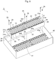
- the end plates 21 are fastened to a housing 40 together with the bottom plate portion 24 using screws 25 inserted through the screw holes 21a (see Fig. 6 ).
- the screws 25 are fastening members for fastening the end plates 21 to the housing 40 as described below.
- the pair of side plates 22 are formed thinner than the end plates 21, and extend along the stacked direction.
- the side plates 22 are formed integrally with the bottom plate portion 24 by, for example, bending a single metal plate in a squared U-shape. It should be noted that the side plates 22 may also be formed separately from the bottom plate portion 24 and then fixed thereto by welding or with screws, for example.
- the section plate 23 is disposed between the battery blocks 10 so as to partition them, and is provided in parallel with the end plates 21.
- the section plate 23 is cuboid in shape, and has a relatively narrow portion along the stacked direction of the battery cells 11. Therefore, as illustrated in Figs. 1 and 2 , the upper surface of the section plate 23 is a narrow face 23a arranged along the stacked direction.
- the section plate 23 has two screw holes 23b with a predetermined distance therebetween.
- the section plate 23 is fastened to the housing 40 together with the bottom plate portion 24 using screws 25 inserted through the screw holes 23b (see Fig. 6 ).
- the screws 25 are fastening members for fastening the section plate 23 to the housing 40 as described below.
- the secondary battery module 1 of present embodiment further includes, in addition to the aforementioned inter-cell bus bars 31, an inter-block bus bar 32 adapted to electrically connect the adjacent battery blocks 10, and bus bars 33 at opposite ends of the module, each bus bar 33 at an end of the module being adapted to electrically connect the positive electrode terminal 14 or the negative electrode terminal 15 of one of the battery cells 11 of each battery block 10 to an external connection terminal 34 of the module arranged near each end plate 21.
- the inter-block bus bar 32 is provided across the section plate 23, and electrically connects the positive electrode terminal 14 of one of the mutually adjacent battery blocks 10 to the negative electrode terminal 15 of the other battery block 10.
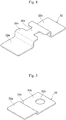
- Fig. 4 is a perspective view of the inter-block bus bar.
- the inter-block bus bar 32 has a cross-section in an approximately hat shape, and includes a flat joint portion 32a adapted to be joined to one of the positive electrode terminal 14 or the negative electrode terminal 15 of one of the mutually adjacent battery blocks 10, a flat joint portion 32b adapted to be joined to the other of the positive electrode terminal 14 or the negative electrode terminal 15 of the other battery block 10, and a protruding portion 32c arranged between the joint portions 32a and 32b and protruding outward from the battery cells 11.
- the center of the protruding portion 32c is provided with a fuse portion 32d that is formed narrower than the other portions of the inter-block bus bar 32. That is, the inter-block bus bar 32 is a bus bar with a fuse function. It should be noted that the fuse portion 32d is arranged in the center of the protruding portion 32c so as to face the narrow face 23a of the section plate 23.
- the inter-block bus bar 32 with such a structure is formed by, for example, machining a part of a single aluminum plate into a narrow shape at a place where the fuse portion 32d is to be formed, and bending the plate into a hat shape. It should be noted that the inter-block bus bar 32 may also be formed using a clad material obtained by joining the protruding portion 32c made of aluminum to the joint portions 32a and 32b each made of copper.
- each bus bar 33 at an end of the module has a plate shape, and one end of the bus bar 33 is electrically connected to the positive electrode terminal 14 or the negative electrode terminal 15 of the battery cell 11 that is most adjacent to one of the end plates 21, while the other end of the bus bar 33 extends toward the end plate 21 and is electrically connected to the external connection terminal 34 of the module.
- Fig. 5 is a perspective view of each bus bar at an end of the module.
- each bus bar 33 at an end of the module is formed by, for example, bending a single aluminum plate into an approximately Z-shape, and includes a joint portion 33a adapted to be joined to the positive electrode terminal 14 or the negative electrode terminal 15 of the battery cell 11 that is most adjacent to one of the end plates 21 and arranged at a relatively high level, an extension portion 33b arranged at a relatively low level and extending toward the end plate 21, and a step portion 33c arranged between the joint portion 33a and the extension portion 33b.
- the tip end of the extension portion 33b is provided with a screw hole 33d.
- the aforementioned external connection terminal 34 of the module is screwed into the screw hole 33d and thus is fixed to the bus bar 33 at the end of the module.
- Each bus bar 33 at an end of the module is fixed to one of the battery cells 11 as the joint portion 33a of the bus bar 33 is welded to the positive electrode terminal 14 or the negative electrode terminal 15 of the battery cell 11.
- the bottom face of the extension portion 33b of the bus bar 33 is away from the upper face of the end plate 21 and thus is electrically insulated from the end plate 21.
- the bottom face of the external connection terminal 34 of the module screwed into the screw hole 33d of the bus bar 33 at the end of the module is away from the upper face of the end plate 21 and thus is electrically insulated from the end plate 21.
- the bus bar 33 at an end of the module with such a structure is provided on each of the opposite sides of the secondary battery module 1 in the stacked direction. That is, one of the bus bars 33 is adapted to electrically connect the positive electrode terminal 14 of the battery cell 11 located at one end in the stacked direction to one external connection terminal 34 of the module, and the other bus bar 33 is adapted to electrically connect the negative electrode terminal 15 of the battery cell 11 located at the other end in the stacked direction to the other external connection terminal 34 of the module.
- the external connection terminal 34 of the module which is electrically connected to the positive electrode terminal 14 of the battery cell 11 via the bus bar 33 at one end of the module, functions as a positive electrode of the external connection terminal of the secondary battery module 1.
- the external connection terminal 34 of the module which is electrically connected to the negative electrode terminal 15 of the battery cell 11 via the bus bar 33 at an end of the module, functions as a negative electrode of the external connection terminal of the secondary battery module 1.
- the inter-block bus bar 32 is provided across the section plate 23, and the inter-block bus bar 32 is provided with the fuse portion 32d.
- the section plate 23 partially forms the holding member 20 and is a portion with a relatively high strength in the secondary battery module 1.
- stress applied to the fuse portion 32d can be reduced, and thus breakage of the fuse portion 32d due to external forces, such as vibration or impact, can be suppressed.
- the fuse portion 32d is provided in the inter-block bus bar 32 so as to face the narrow face 23a of the section plate 23, stress applied to the fuse portion 32d can be reduced, and in comparison with when the fuse portion 32d is provided facing the wide face (that is, a face extending in the longitudinal direction) of the section plate 23, for example, the protruding portion 32c of the inter-block bus bar 32 can be made shorter. Consequently, the material used for the inter-block bus bar 32 can be reduced, and a cost reduction can thus be achieved.
- the secondary battery module 1 when a housing adapted to house the battery blocks 10, which are held by the holding member 20, is provided, a fastening member for fastening the section plate 23 to the housing is preferably disposed near the fuse portion 32d.
- the secondary battery module 1 further includes a housing 40 adapted to house the battery blocks 10 held by the holding member 20.
- the housing 40 is in the shape of a box, and houses two battery blocks 10 held by the holding member 20.
- Fig. 6 illustrates the housing 40 without a cover, the housing 40 may include a cover.
- a bottom portion 41 of the housing 40 is provided with screw holes 41a corresponding to the screw holes 21a of the end plates 21 and the screw holes 23b of the section plate 23.
- the inner wall of each screw hole 21a has an inside screw formed therein.
- the battery blocks 10 held by the holding member 20 are fastened to the housing 40 with the screws 25 that have been inserted through the screw holes 21a and 23b and further through the screw holes 41a.
- the screws 25 for fastening the section plate 23 to the housing 40 are disposed near the fuse portion 32d. Accordingly, the effect of reducing the stress applied to the fuse portion 32d can be further increased. Thus, breakage of the fuse portion 32d due to external forces, such as vibration or impact, can be suppressed.
- the fuse portion 32d may have the same width as the other portions of the inter-block bus bar 32 and be formed thinner than the other portions of the inter-block bus bar 32.
- the fuse portion 32d may be formed narrower and thinner than the other portions of the inter-block bus bar 32. In this manner, changing the configuration of the fuse portion 32d as appropriate can increase the versatility of the fuse portion 32d and save materials more easily.
- Fig. 7 is a plan view of a secondary battery module according to a second embodiment.
- a secondary battery module 1A of the present embodiment differs from the secondary battery module of the aforementioned first embodiment in that one of the two bus bars 33 at opposite ends of the module is a bus bar with a fuse function.
- the other structures are similar to those of the first embodiment. Thus, overlapped descriptions will be omitted.
- the inter-block bus bar 32 is not provided with the fuse portion 32d.
- one of the two bus bars 33 at opposite ends of the module i.e., the bus bar 33A at an end of the module on the right side in Fig. 7
- the fuse portion 33e is formed between the screw hole 33d of the extension portion 33b and the step portion 33c, and is narrower than the other portions of the bus bar 33A at the end of the module.
- the bus bar 33A at the end of the module is formed by, for example, machining a part of a single aluminum plate into a narrow shape at a place where the fuse portion 33e is to be formed and forming the screw hole 33d, and then bending the plate into a Z-shape.
- the end plates 21 partially form the holding member 20 and are portions with a relatively high strength in the secondary battery module 1.
- the bus bar 33A at an end of the module, which has the fuse portion 33e is provided near one of the end plates 21 with a relatively high strength, stress applied to the fuse portion 33e can be reduced, and thus breakage of the fuse portion 33e due to external forces, such as vibration or impact, can be suppressed.
- a screw 25 for fastening the end plate 21 to the housing 40 is preferably disposed near the fuse portion 33e. Accordingly, the effect of reducing the stress applied to the fuse portion 33e can be further increased.
- both the two bus bars 33 at opposite ends of the module may be bus bars each having a fuse function as appropriate, or alternatively, one of the two bus bars 33 at the opposite ends of the module may be a bus bar with a fuse function, and further, the inter-block bus bar 32 may also be a bus bar with a fuse function.
- Fig. 8 is a plan view of a secondary battery module according to a third embodiment.
- a secondary battery module 1B of the present embodiment differs from the aforementioned second embodiment in having only one battery block 10.
- the other structures are similar to those of the second embodiment. Thus, overlapped descriptions will be omitted.
- the secondary battery module 1B includes one battery block 10 and a holding member 20A adapted to hold the battery block 10. Therefore, the holding member 20A does not include the section plate 23 described in the first and second embodiments.
- one of the two bus bars 33 at opposite ends of the module (the bus bar 33A at an end of the module on the right side in Fig. 8 ) is provided with the fuse portion 33e.
- the present invention is not limited thereto, and various designs changes can be made without departing from the spirit and scope of the present invention recited in the claims.
- the bus bars 33 at opposite ends of the module may extend toward the end plates 21, the bus bars 33 at the opposite ends of the module may extend toward the side plates 22.
- one of the external connection terminals 34 of the module may be fixed to the extension portion, which extends toward one of the side plates 22, of one of the bus bars 33 at the opposite ends of the module.
Landscapes
- Chemical & Material Sciences (AREA)
- Chemical Kinetics & Catalysis (AREA)
- Electrochemistry (AREA)
- General Chemical & Material Sciences (AREA)
- Inorganic Chemistry (AREA)
- Connection Of Batteries Or Terminals (AREA)
- Battery Mounting, Suspending (AREA)
Applications Claiming Priority (2)
| Application Number | Priority Date | Filing Date | Title |
|---|---|---|---|
| JP2018118425 | 2018-06-22 | ||
| PCT/JP2019/007086 WO2019244402A1 (fr) | 2018-06-22 | 2019-02-25 | Module de batterie secondaire |
Publications (2)
| Publication Number | Publication Date |
|---|---|
| EP3813152A1 true EP3813152A1 (fr) | 2021-04-28 |
| EP3813152A4 EP3813152A4 (fr) | 2022-04-20 |
Family
ID=68983626
Family Applications (1)
| Application Number | Title | Priority Date | Filing Date |
|---|---|---|---|
| EP19822527.8A Pending EP3813152A4 (fr) | 2018-06-22 | 2019-02-25 | Module de batterie secondaire |
Country Status (5)
| Country | Link |
|---|---|
| US (2) | US11646474B2 (fr) |
| EP (1) | EP3813152A4 (fr) |
| JP (2) | JP6983314B2 (fr) |
| CN (2) | CN112243549B (fr) |
| WO (1) | WO2019244402A1 (fr) |
Cited By (1)
| Publication number | Priority date | Publication date | Assignee | Title |
|---|---|---|---|---|
| WO2024146856A1 (fr) * | 2023-01-04 | 2024-07-11 | Volvo Car Corporation | Module de batterie comprenant deux sous-modules |
Families Citing this family (13)
| Publication number | Priority date | Publication date | Assignee | Title |
|---|---|---|---|---|
| US11545706B2 (en) * | 2018-06-19 | 2023-01-03 | Sk Innovation Co., Ltd. | Battery cell having a plurality of electrodes and battery module using the same |
| CN112243549B (zh) * | 2018-06-22 | 2024-05-24 | 日本汽车能源株式会社 | 二次电池模块 |
| DE112019006495T5 (de) * | 2018-12-27 | 2021-09-02 | Gs Yuasa International Ltd. | Energiespeichervorrichtung |
| JP7144488B2 (ja) * | 2020-07-30 | 2022-09-29 | プライムプラネットエナジー&ソリューションズ株式会社 | 蓄電モジュール |
| KR102944936B1 (ko) | 2020-10-23 | 2026-03-27 | 주식회사 엘지에너지솔루션 | 나사산이 있는 버스바를 포함하는 배터리 모듈 |
| KR102720302B1 (ko) * | 2021-03-31 | 2024-10-22 | 컨템포러리 엠퍼렉스 테크놀로지 (홍콩) 리미티드 | 버스바, 배터리 및 전기 장치 |
| KR102946290B1 (ko) * | 2021-06-14 | 2026-03-30 | 주식회사 엘지에너지솔루션 | 안전성이 향상된 배터리 팩 |
| JP7768726B2 (ja) * | 2021-10-25 | 2025-11-12 | 株式会社東芝 | 電池モジュール |
| JP7455793B2 (ja) * | 2021-11-17 | 2024-03-26 | プライムプラネットエナジー&ソリューションズ株式会社 | 電池モジュール |
| EP4250464A4 (fr) | 2022-01-25 | 2024-05-15 | Eve Power Co., Ltd. | Ensemble barre omnibus et module de batterie de traction cylindrique |
| CN115000637B (zh) * | 2022-06-22 | 2025-07-18 | 楚能新能源股份有限公司 | 电池包电芯连接件的自动安装机构 |
| KR20240024622A (ko) * | 2022-08-17 | 2024-02-26 | 주식회사 엘지에너지솔루션 | 전지 모듈 및 이를 포함하는 전지팩 |
| EP4730542A1 (fr) * | 2024-10-17 | 2026-04-22 | Samsung Sdi Co., Ltd. | Module de batterie et bloc-batterie le comprenant |
Family Cites Families (22)
| Publication number | Priority date | Publication date | Assignee | Title |
|---|---|---|---|---|
| JP2003045305A (ja) * | 2001-07-30 | 2003-02-14 | Uchihashi Estec Co Ltd | 薄型ヒューズ |
| JP5105394B2 (ja) * | 2006-03-15 | 2012-12-26 | 日立ビークルエナジー株式会社 | 電池ユニット |
| JP5285961B2 (ja) * | 2008-05-27 | 2013-09-11 | 株式会社ケーヒン | 組電池の電源制御装置 |
| JP2012138239A (ja) * | 2010-12-27 | 2012-07-19 | Panasonic Corp | 電池モジュール |
| JP2012181977A (ja) * | 2011-03-01 | 2012-09-20 | Mitsubishi Heavy Ind Ltd | 二次電池モジュール |
| JP2013073929A (ja) | 2011-09-29 | 2013-04-22 | Gs Yuasa Corp | 電池パック |
| WO2013103244A1 (fr) | 2012-01-03 | 2013-07-11 | 주식회사 엘지화학 | Bloc batterie et barre de connexion pour ledit bloc batterie |
| US20130252052A1 (en) | 2012-03-21 | 2013-09-26 | GM Global Technology Operations LLC | Integrated Busbar, Terminal Pin And Circuit Protection For Sensing Individual Battery Cell Voltage |
| JP6045802B2 (ja) * | 2012-03-21 | 2016-12-14 | 株式会社東芝 | 二次電池装置 |
| US9912018B2 (en) | 2012-03-21 | 2018-03-06 | GM Global Technology Operations LLC | Integration of a voltage sense trace fuse into a battery interconnect board |
| JP5939007B2 (ja) | 2012-04-13 | 2016-06-22 | トヨタ自動車株式会社 | 蓄電装置 |
| JP6166356B2 (ja) * | 2013-03-28 | 2017-07-19 | 日立オートモティブシステムズ株式会社 | 電池モジュール |
| JP2014229384A (ja) * | 2013-05-20 | 2014-12-08 | 三菱自動車工業株式会社 | バスバー |
| US20160126514A1 (en) * | 2013-06-19 | 2016-05-05 | Hitachi Automotive Systems, Ltd. | Battery module |
| KR101749721B1 (ko) * | 2014-04-04 | 2017-06-21 | 주식회사 엘지화학 | 퓨즈 어셈블리를 포함하는 전지모듈 어셈블리 |
| DE102015113374B4 (de) | 2014-08-18 | 2023-08-24 | GM Global Technology Operations LLC (n. d. Gesetzen des Staates Delaware) | Anordnung zum erfassen einer spannung, batteriestapel sowie verfahren zum bereitstellen einer elektrischen konnektivität zu einem batteriestapel eines kraftfahrzeugantriebssystems |
| WO2016136249A1 (fr) * | 2015-02-27 | 2016-09-01 | 三洋電機株式会社 | Batterie secondaire, et batterie assemblée équipée d'une pluralité de batteries secondaires |
| JP2017123280A (ja) * | 2016-01-07 | 2017-07-13 | トヨタ自動車株式会社 | 電池モジュール |
| CN107305938A (zh) * | 2016-04-25 | 2017-10-31 | 比亚迪股份有限公司 | 电池连接片、电池模组以及动力电池包 |
| US10062977B2 (en) * | 2016-10-14 | 2018-08-28 | Inevit Llc | Module-to-module power connector between battery modules of an energy storage system and arrangement thereof |
| JP6955870B2 (ja) | 2017-01-24 | 2021-10-27 | 藤森工業株式会社 | 積層体、ブリスター容器、プレススルーパッケージ、及び積層体の製造方法 |
| CN112243549B (zh) | 2018-06-22 | 2024-05-24 | 日本汽车能源株式会社 | 二次电池模块 |
-
2019
- 2019-02-25 CN CN201980035841.7A patent/CN112243549B/zh active Active
- 2019-02-25 WO PCT/JP2019/007086 patent/WO2019244402A1/fr not_active Ceased
- 2019-02-25 US US17/059,976 patent/US11646474B2/en active Active
- 2019-02-25 JP JP2020525243A patent/JP6983314B2/ja active Active
- 2019-02-25 EP EP19822527.8A patent/EP3813152A4/fr active Pending
- 2019-02-25 CN CN202410527251.9A patent/CN118448818A/zh active Pending
-
2021
- 2021-11-22 JP JP2021189207A patent/JP7191184B2/ja active Active
-
2023
- 2023-04-03 US US18/194,932 patent/US12315954B2/en active Active
Cited By (1)
| Publication number | Priority date | Publication date | Assignee | Title |
|---|---|---|---|---|
| WO2024146856A1 (fr) * | 2023-01-04 | 2024-07-11 | Volvo Car Corporation | Module de batterie comprenant deux sous-modules |
Also Published As
| Publication number | Publication date |
|---|---|
| CN118448818A (zh) | 2024-08-06 |
| US12315954B2 (en) | 2025-05-27 |
| US20210218114A1 (en) | 2021-07-15 |
| JP7191184B2 (ja) | 2022-12-16 |
| WO2019244402A1 (fr) | 2019-12-26 |
| EP3813152A4 (fr) | 2022-04-20 |
| JPWO2019244402A1 (ja) | 2021-03-11 |
| CN112243549A (zh) | 2021-01-19 |
| JP6983314B2 (ja) | 2021-12-17 |
| JP2022020832A (ja) | 2022-02-01 |
| US20230238658A1 (en) | 2023-07-27 |
| CN112243549B (zh) | 2024-05-24 |
| US11646474B2 (en) | 2023-05-09 |
Similar Documents
| Publication | Publication Date | Title |
|---|---|---|
| US12315954B2 (en) | Secondary battery module | |
| CN104064699B (zh) | 蓄电装置 | |
| CN108028332B (zh) | 蓄电装置 | |
| EP2562843B1 (fr) | Module de batterie | |
| EP2615663B1 (fr) | Module de batterie et unité d'alimentation en énergie | |
| EP2615664B1 (fr) | Unité de source de puissance | |
| US9112202B2 (en) | Battery module | |
| KR102453383B1 (ko) | 이차 전지 모듈 | |
| JP6257951B2 (ja) | 電池モジュール | |
| EP2482361A1 (fr) | Bloc batterie | |
| JP6629140B2 (ja) | 蓄電モジュール | |
| CN103238232A (zh) | 电池模块和电池组 | |
| KR20140094207A (ko) | 전지 모듈 | |
| JP2014022169A (ja) | 電池用配線モジュール | |
| KR102760922B1 (ko) | 배터리, 전기기기 및 배터리의 제조 방법 | |
| WO2020105502A1 (fr) | Module de stockage d'énergie | |
| KR101147172B1 (ko) | 이차 전지 및 전지 모듈 | |
| EP4123803A1 (fr) | Ligne de détection de tension et module de ligne de détection de tension | |
| JP6613791B2 (ja) | 電池パック | |
| WO2020059298A1 (fr) | Module de batterie | |
| EP2605310B1 (fr) | Module de batterie secondaire | |
| JP6772875B2 (ja) | 蓄電装置 | |
| WO2019244413A1 (fr) | Bloc-batterie | |
| WO2024045056A1 (fr) | Batterie et dispositif électrique | |
| KR20240083049A (ko) | 배터리 팩 |
Legal Events
| Date | Code | Title | Description |
|---|---|---|---|
| STAA | Information on the status of an ep patent application or granted ep patent |
Free format text: STATUS: THE INTERNATIONAL PUBLICATION HAS BEEN MADE |
|
| PUAI | Public reference made under article 153(3) epc to a published international application that has entered the european phase |
Free format text: ORIGINAL CODE: 0009012 |
|
| STAA | Information on the status of an ep patent application or granted ep patent |
Free format text: STATUS: REQUEST FOR EXAMINATION WAS MADE |
|
| 17P | Request for examination filed |
Effective date: 20210122 |
|
| AK | Designated contracting states |
Kind code of ref document: A1 Designated state(s): AL AT BE BG CH CY CZ DE DK EE ES FI FR GB GR HR HU IE IS IT LI LT LU LV MC MK MT NL NO PL PT RO RS SE SI SK SM TR |
|
| AX | Request for extension of the european patent |
Extension state: BA ME |
|
| DAV | Request for validation of the european patent (deleted) | ||
| DAX | Request for extension of the european patent (deleted) | ||
| REG | Reference to a national code |
Ref country code: DE Ref legal event code: R079 Free format text: PREVIOUS MAIN CLASS: H01M0002340000 Ipc: H01M0050583000 |
|
| A4 | Supplementary search report drawn up and despatched |
Effective date: 20220318 |
|
| RIC1 | Information provided on ipc code assigned before grant |
Ipc: H01M 50/507 20210101ALI20220314BHEP Ipc: H01M 50/503 20210101ALI20220314BHEP Ipc: H01M 50/583 20210101AFI20220314BHEP |
|
| STAA | Information on the status of an ep patent application or granted ep patent |
Free format text: STATUS: EXAMINATION IS IN PROGRESS |
|
| 17Q | First examination report despatched |
Effective date: 20240123 |