EP3814565B1 - Support de tissu - Google Patents
Support de tissu Download PDFInfo
- Publication number
- EP3814565B1 EP3814565B1 EP18737200.8A EP18737200A EP3814565B1 EP 3814565 B1 EP3814565 B1 EP 3814565B1 EP 18737200 A EP18737200 A EP 18737200A EP 3814565 B1 EP3814565 B1 EP 3814565B1
- Authority
- EP
- European Patent Office
- Prior art keywords
- support
- support table
- section
- elongated base
- base section
- Prior art date
- Legal status (The legal status is an assumption and is not a legal conclusion. Google has not performed a legal analysis and makes no representation as to the accuracy of the status listed.)
- Active
Links
Images




Classifications
-
- D—TEXTILES; PAPER
- D03—WEAVING
- D03J—AUXILIARY WEAVING APPARATUS; WEAVERS' TOOLS; SHUTTLES
- D03J1/00—Auxiliary apparatus combined with or associated with looms
- D03J1/22—Temples
- D03J1/223—Temples acting on the full width of cloth
-
- D—TEXTILES; PAPER
- D03—WEAVING
- D03D—WOVEN FABRICS; METHODS OF WEAVING; LOOMS
- D03D49/00—Details or constructional features not specially adapted for looms of a particular type
- D03D49/04—Control of the tension in warp or cloth
- D03D49/22—Back rests; Lease rods; Brest beams
Definitions
- the invention relates to a fabric support for a weaving machine and to a method for manufacturing such a fabric support.
- WO 2008/031519 A1 shows a fabric support, which is fitted to a frame of a weaving machine.
- the fabric support comprises several support profiles, wherein each support profile has an elongated base section adapted for being fastened to the frame of the weaving machine and a support table section formed integrally with the elongated base section.
- Each of the support table sections comprises a protruding lip portion arranged at their distal end and an adjoining cantilever portion, which cantilever portions extend upward and rearward from the elongated base section.
- the support profiles are arranged such that adjacent support profiles abut each other or such that adjacent support profiles are arranged with gaps between them, wherein an elongated guide element is attached to the lip portions, which bridges the gaps between the support profiles.
- the cantilever portions are provided with openings for allowing a passing of weft detectors, nozzles, such as relay nozzles or stretching nozzles, or other elements mounted to a sley of the weaving machine, during beat-up and avoiding interferences between the fabric support and the nozzles or other elements.
- JPH04202833 A shows a fabric support comprising an elongated base section to which a support profile and several support table sections are mounted.
- a fabric support for a weaving machine with a support profile and with at least one support table segment formed separately from the support profile wherein the support profile has an elongated base section adapted for being fastened to a frame of the weaving machine and a support table section formed integrally with the elongated base section, wherein a length of the support table section is shorter than a length of the elongated base section, wherein the support table section comprises a protruding lip portion arranged at its distal end and an adjoining cantilever portion, which cantilever portion extends at least upward from the elongated base section, wherein the at least one support table segment comprises a protruding lip portion arranged at its distal end and an adjoining cantilever portion, and wherein the at least one support table segment is attached to the elongated base section in a position offset to the support table section in a longitudinal direction of the support profile.
- the at least one support table segment When mounting the at least one support table segment to the support profile, the at least one support table segment can be aligned with the support profile. A pre-assembled unit of the support profile with support table segments can be mounted to the weaving machine.
- the at least one support table segment and the support profile are made of the same material, for example made of an extruded aluminum or aluminum alloy.
- the at least one support table segment is made from a more rigid material than the material of the support profile.
- the at least one support table segment is made from steel.
- a material thickness of the at least one support table segment is at least partly, less than a material thickness of the support table section, in particular a material thickness of the cantilever portion of the at least one support table segment is less than a material thickness of the cantilever portion of the support table section.
- the shape of the cantilever portion of the at least one support table segment and the shape of the cantilever portion of the support table section are chosen such that the respective lip portions are arranged near the beat-up line.
- the cantilever portions extend at least upward from the elongated base section.
- the cantilever portions in one embodiment extend along an at least essentially straight line having a vertical component.
- the cantilever portions are arc-shaped, wherein a temple roller can be placed in front of the lip portions in a pulling direction of the woven fabric.
- a back side of the cantilever portion of the at least one support table segment protrudes less from the elongated base section towards a reed than a back side of the cantilever portion of the support table section.
- a shape of the cantilever portion of the at least one support table segment differs from the shape of the cantilever portion of the support table section.
- the cantilever portion of the at least one support table segment and the cantilever portion of the support table section extend along an at least essentially identical arc-shaped or straight line.
- a thickness of the cantilever portion of the at least one support table segment is at least in some areas less than a thickness of the cantilever portion of the support table section. This allows that the back side of the cantilever portion of the at least one support table segment protrudes less from the elongated base section towards the reed than the back side of the cantilever portion of the support table section.
- the cantilever portion of the at least one support table segment in preferred embodiments is provided with at least one opening. Such an opening allows for a passing of elements, such as nozzles, mounted to the sley.
- the cantilever portion is provided with two openings dividing the cantilever portion into three ribs, which ribs are offset from one another in the longitudinal direction.
- the at least one support table segment further comprises a mounting portion adapted for mounting the at least one support table segment to the elongated base section.
- the mounting portion in preferred embodiments is provided with at least one through hole for receiving a fastening element, in particular for receiving a fastening screw.
- the mounting portion is provided with two through holes which are offset from one another in the longitudinal direction of the fabric support.
- the lip portion of the support table section and the lip portion of the at least one support table segment function as guiding surfaces for the woven fabric, wherein for example a surface treatment or surface coating is applied to the lip portion of the support table section for enhancing the guiding characteristics.
- the fabric support further comprises an elongated guide element, wherein the elongated guide element is mounted to the lip portions of the support table section and the at least one support table segment.
- the support table section and the at least one support table segment in one embodiment are arranged such that adjacent lip portions abut each other. In other embodiments, the support table section and the at least one support table segment are arranged such that gaps are formed between adjacent lip portions, wherein the elongated guide element bridges the gaps between the lip portions.
- the lip portion of the at least one support table segment and the lip portion of the support table section each have a flat top surface for mounting the elongated guide element.
- the support profile has an auxiliary support section, which auxiliary support section extends in the longitudinal direction of the support profile, wherein in particular a length of the auxiliary support section is at least essentially the same as the length of the elongated base section, wherein in particular an elongated auxiliary guide element is mounted to the auxiliary support section.
- the auxiliary support section is formed integrally with the support profile. Hence, no additional mounting step is required for mounting the auxiliary support section.
- the elongated base section in preferred embodiments is provided with a mounting surface for mounting the elongated base section to the frame of the weaving machine and with an attachment surface to which the at least one support table segment is mounted.
- the mounting surface is for example a bottom surface of the elongated base section.
- the mounting surface is provided with alignment elements and/or through holes for receiving fastening screws.
- the attachment surface is inclined with respect to the mounting surface about an axis parallel to the longitudinal direction of the elongated base section.
- the arrangement of the attachment surface is suitably chosen by the person skilled in the art for avoiding forces acting only in a direction perpendicular to the fastening elements, in particular to the fastening screws, and/or for guaranteeing a sufficient material thickness of the elongated base section in an area surrounding the fastening elements.
- the at least one support table segment is aligned with respect to the support profile by means of the fastening elements.
- the at least one support table segment abuts against an abutment surface of the elongated base section, wherein the attachment surface and the abutment surface are set at an angle to each other, in particular at an angle of about 70° to about 120°.
- a method for manufacturing a fabric support for a weaving machine having a support profile and at least one support table segment formed separately from the support profile, wherein the support profile has an elongated base section adapted for being fastened to a frame of the weaving machine and a support table section formed integrally with the elongated base section, wherein a length of the support table section is shorter than a length of the elongated base section, wherein the support table section comprises a protruding lip portion arranged at its distal end and an adjoining cantilever portion which cantilever portion extends at least upward from the elongated base section, and wherein the at least one support table segment comprises a protruding lip portion arranged at its distal end and an adjoining cantilever portion, the method comprising machining the elongated base section in a position offset to the support table section in a longitudinal direction of the support profile for forming an attachment surface, and attaching the at least one support table segment formed separately from the support profile
- the support profile is made of an extruded aluminum or aluminum alloy, wherein by machining the support profile the length of the support table section is shortened, such that the length of the support table section becomes shorter than the length of the elongated base section.
- the at least one support table segment is formed such that after mounting the at least one support table segment a back side of its cantilever portion protrudes less from the elongated base section towards a reed than a back side of the cantilever portion of the support table section. Hence, in the region of the at least one support table segment, an additional installation space for elements mounted to the sley of the weaving machine is provided.
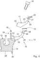
- Fig. 1 shows schematically in a side view a part of a weaving machine with a frame 2, a sley 3 carrying a reed 4 and a fabric support 1 mounted to the frame 2 of the weaving machine.
- the weaving machine is an airjet weaving machine, wherein during weaving, a weft thread (not shown) is inserted into a weaving shed formed by warp threads (not shown) by means of an airflow in an U-shaped insertion channel 5 of the reed 4, which airflow transports the weft thread through the U shaped insertion channel 5.
- This airflow is generated by a main nozzle (not shown) and by a number of relay nozzles (not shown) that are arranged one after the other in an insertion direction along the U-shaped insertion channel 5.
- auxiliary nozzles 6 are mounted on the sley 3.
- the auxiliary nozzles 6 are for example stretching nozzles arranged at an arrival side of the insertion as shown for example in WO 2015/177155 A1 .
- the auxiliary nozzles 6 are provided on a holder 7 with a tongue 8, which is inserted in a groove provided on a reed beam 9 and clamped between a key 10 and the reed beam 9 for fixing the holder 7 to the sley 3.
- a woven fabric (not shown) is supported by the fabric support 1, which comprises several support table segments 11 and a support profile 12 to which the support table segments 11 are mounted, which fabric support 1 will be described in more detail below.
- the fabric support 1 comprises an elongated guide element 13 arranged at a distal end that enters into the U-shaped insertion channel 5.
- the support profile 12 has an auxiliary support section 18, which extends in the longitudinal direction of the support profile 12 and is arranged upfront of the elongated guide element 13 for supporting a woven fabric at a distance from the beat-up line in a pulling direction of the woven fabric.
- the fabric support 1 is mounted on the frame 2 and fastened with respect to a groove 31 of the frame 2 using fastening screws (not shown). As shown in Fig.
- the sley 3 with the reed 4 and the auxiliary nozzles 6 are moved towards the fabric support 1, wherein the support table segments 11 are formed such that interference between the fabric support 1 and the auxiliary nozzles 6 is avoided.
- the fabric support 1 will be described in more detail with reference to Figs. 2 to 12 .
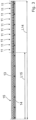
- Fig. 2 is a perspective view of an end of a fabric support 1 with a support profile 12, with several, in the embodiment shown ten support table segments 11 and with an elongated guide element 13.
- the support profile 12 has an elongated base section 14 adapted for being fastened to the frame 2 of the weaving machine (see Fig. 1 ) and a support table section 15 formed integrally with the elongated base section 14.
- a length L15 of the support table section 15 is shorter than a length L14 of the elongated base section 14 and the support table segments 11 are attached to the elongated base section 14 of the support profile 12 in a position offset to the support table section 15 in a longitudinal direction of the support profile 12.
- each support table segment 11 is mounted to the elongated base section 14 by means of two fastening screws 16.
- the support table segments 11 are each provided with openings 37 and the support table section 15 is provided with openings 17, wherein if possible relay nozzles, auxiliary nozzles or other elements attached to the sley 3 of the weaving machine (see Fig. 1 ) are arranged in the region of the openings 17, 37 for avoiding an interference with the fabric support 1 upon beat-up and allowing a movement of the elements through the openings or into the openings during beat-up.
- cantilever portions 23 of the support table segments 11 are each provided with two openings 37 such that three ribs 38 are formed, which are offset in the longitudinal direction of the fabric support 1. In other embodiments, more than two openings 37 or only one opening 37 is provided. Similar, a cantilever portion 21 of the support table section 15 is provided with openings 17 such that a plurality of ribs 39 is formed.
- a length of the auxiliary support section 18 is at least essentially the same as the length L14 of the elongated base section 14.
- an elongated auxiliary guide element 19 is mounted to the auxiliary support section 18.
- Fig. 4 is an exploded side view of the fabric support 1
- Fig. 5 is a side view of the fabric support 1 comprising the support profile 12, the support table segments 11, the elongated guide element 13 mounted to the support profile 12 and the support table segments 11, and the elongated auxiliary guide element 19.
- the support table section 15 comprises a protruding lip portion 20 arranged at its distal end and an adjoining cantilever portion 21, which cantilever portion 21 extends upward and towards the reed 4 (see Fig. 1 ) from the elongated base section 14.
- the support table segments 11 each comprise a lip portion 22 arranged at the distal end and an adjoining cantilever portion 23, wherein when mounted to the elongated base section 14, the cantilever portions 23 of the support table segments 11 extend upward and towards the reed 4 (see Fig. 1 ) from the elongated base section 14.
- the support table segments 11 further each comprise a mounting portion 24 adapted for mounting the support table segments 11 to the elongated base section 14.
- the lip portion 20 of the support table section 15 and the lip portions 22 of the support table segments 11 are at least essentially identical in design and, when the support table segments 11 are mounted to the elongated base section 14, the lip portions 20, 22 are aligned with each other.
- the lip portions 22 of the support table segments 11 and the lip portion 20 of the support table section 15 each have a flat top surface for mounting the elongated guide element 13.
- back sides 25 of the cantilever portions 23 of the support table segments 11 protrude less from the elongated base section 14 towards the reed 4 (see Fig. 1 ) than a back side 26 of the cantilever portion 21 of the support table section 15. Due to this design, an additional installation space for elements mounted to the sley 3, for example the auxiliary nozzle 6 shown in Fig. 1 , is provided and those elements can be arranged in a position behind a support table segment 11, which is not provided with an opening 37 (see Fig. 2 ), or behind a support table segment 11 in a position next to a rib 38 of the cantilever portion 23.
- a thickness 27 of the cantilever portions 23 of the support table segments 11 is partly less than a thickness 28 of the cantilever portion 21 of the support table section 15.
- the support table segments 11 are made from a more rigid material than the material of the support profile 12.
- the elongated base section 14 is provided with a mounting surface 29 for mounting the elongated base section 14 to the frame 2 (see Fig. 1 ) of the weaving machine.
- the mounting surface 29 is provided at a bottom of the elongated base section 14.
- a nose 30 is provided at a rear end of the mounting surface 29 for aligning the elongated base section 14 with the frame 2.
- the elongated base section 14 is further provided with an attachment surface 32 to which the support table segments 11 are mounted.
- the attachment surface 32 is inclined with respect to the mounting surface 29 about an axis parallel to longitudinal direction of the elongated base section 14. This arrangement allows for a sufficiently large attachment surface 32.
- the attachment surface 32 can be arranged in parallel to the mounting surface 29.
- the support table segments 11 further abut against an abutment surface 33 of the elongated base section 14, wherein the attachment surface 32 and the abutment surface 33 are set at least essentially perpendicular to one another.
- the attachment surface 32 and the abutment surface 33 can be machined with high accuracy, so that support table segments 11 can be attached with high accuracy in position with respect to the elongated base section 14 in the longitudinal direction of the elongated base section 14 of the support profile 12.
- the mounting portions 24 are each provided with two through holes 34 (only one visible in Fig. 5 ) for receiving the two fastening screws 16 (see Fig. 8 ). Above the through holes 34 there is an almost semi-circular cut-out for the head of the screw 16 (see Figs. 11 and 12 ).
- the elongated base section 14 is further provided with a groove 35 to which additional elements (not shown), such as additional guiding elements can be mounted.
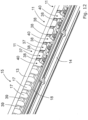
- Figs. 6 , 8 and 12 show in perspective views a part of the support profile 12 of the fabric support 1 respectively prior, upon and after mounting of the support table segments 11 and the elongated guide element 13 to the support profile 12.
- Fig. 7 shows a top view of Fig. 6
- Fig. 10 shows a top view of Fig. 9 .
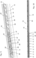
- Fig. 6 shows in a perspective view from a back a part of the support profile 12 of the fabric support 1 prior to mounting the support table segments 11.
- the length of the support table section 15 is shorter than the length of the elongated base section 14, wherein in a position offset to the support table section 15 in the longitudinal direction of the support profile 12 the elongated base section 14 is machined for forming the attachment surface 32 and the abutment surface 33.
- the support profile 12 is machined for example by milling.
- the attachment surface 32 is provided with threaded holes 36 for receiving fastening screws 16 (see Fig. 8 ).
- the threaded holes 36 can be provided with high accuracy in the attachment surface 32, so that the support table segments 11 can be attached with high accuracy in position with respect to the attachment surface 32.
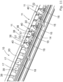
- Figs. 8 and 9 show the part of the support profile 12 of Fig. 6 from the back upon and after mounting support table segments 11, respectively.
- Fig. 11 shows the part of the support profile of Fig. 6 from the front after mounting support table segments 11.
- the lip portions 22 of the support table segments 11 are aligned with the lip portion 20 of the support table section 15.
- the lip portions 22 of the support table segments 11 and the lip portion 20 of the support table section 15 are arranged with gaps 40 there between in the longitudinal direction. The gaps 40 are bridged after attaching the elongated guide profile 13 as shown in Figs. 2 , 3 and 12 .
- the cantilever portions 23 of adjoining support table segments 11 are arranged with gaps 40 there between, wherein elements, such as auxiliary nozzles (not shown), mounted to a sley 3 (see Fig. 1 ) can be arranged in the position of the gaps 40 or the openings 17, 37.
- elements such as auxiliary nozzles (not shown), mounted to a sley 3 (see Fig. 1 ) can also be arranged at the height of the position of the ribs 38.
- support table segments 11 are mounted to the support profile 12 at one side of the support table section 15 only.
- the support table segments 11 are arranged at a right side of the support table section 15 of the support profile 12, which is arranged for example at an arrival side of an inserted weft thread.
- the support table segments 11 are arranged at a left side of the support table section 15 of the support profile 12 in the perspective view of Fig. 2 .
- support table segments 11 are arranged between two support table sections 15 of a support profile 12.
- support table segments 11 are mounted in several zones along the width of the elongated base 14 of the support profile 12 that is provided with several support table sections 15 along the width of elongated base 14 of the support profile 12. For this purpose, for example, several zones of the support profile 12 are machined for forming attachment surfaces 32 for the support table segments 11.
- the support table segments 11 are fixed with screws 16 to the attachment surface 32 of the elongated base section 14, in an alternative embodiment the support table segments 11 can be glued or welded to the attachment surface 32 of the elongated base section 14.
- the fabric support 1 is not limited to the embodiment described by way of example and illustrated in the drawings. Alternatives and combinations of the described and illustrated embodiments that fall under the claims are also possible.
- the fabric support 1 is not provided with an auxiliary support section 18.
- the elongated base section 14 is not provided with a groove 35. In still another embodiment, more than one groove 35 is provided.
Landscapes
- Engineering & Computer Science (AREA)
- Textile Engineering (AREA)
- Looms (AREA)
Claims (13)
- Support de tissu pour une machine à tisser avec un profil de support (12) et avec au moins un segment de table de support (11) formé séparément du profil de support (12), dans lequel le profil de support (12) a une section de base allongée (14) adaptée à être fixée sur un châssis (2) de la machine à tisser et une section de table de support (15), dans lequel la section de table de support (15) comprend une partie de lèvre saillante (20) disposée à son extrémité distale et une partie en porte-à-faux (21) adjacente, laquelle partie en porte-à-faux (21) s'étend au moins vers le haut de la section de base allongée (14), dans lequel l'au moins un segment de table de support (11) comprend une partie de lèvre (22) saillante disposée à son extrémité distale et une partie en porte-à-faux (23) adjacente, et dans lequel l'au moins un segment de table de support (11) est fixé à la section de base allongée (14) dans une position décalée par rapport à la section de table de support (15) dans une direction longitudinale du profil de support (12), caractérisé en ce que la section de table de support (15) est formée intégralement avec la section de base allongée (14), dans lequel une longueur de la section de table de support (15) est plus courte qu'une longueur de la section de base allongée (14).
- Support de tissu selon la revendication 1, caractérisé en ce que l'au moins un segment de table de support (11) est réalisé dans un matériau plus rigide que le matériau du profil de support (12).
- Support de tissu selon la revendication 1 ou 2, caractérisé en ce qu'une épaisseur de matériau de la partie en porte-à-faux (23) d'au moins un segment de table de support (11) est au moins en partie inférieure à l'épaisseur de matériau de la partie en porte-à-faux (21) de la section de table de support (15).
- Support de tissu selon la revendication 1, 2 ou 3, caractérisé en ce qu'un côté arrière (25) de la partie en porte-à-faux (23) d'au moins un segment de table de support (11) fait saillie moins de la section de base allongée (14) vers un peigne (4) qu'un côté arrière (26) de la partie en porte-à-faux (21) de la section de table de support (15).
- Support de tissu selon l'une quelconque des revendications 1 à 4, caractérisé en ce qu'une épaisseur (27) de la partie en porte-à-faux (23) d'au moins un segment de table de support (11) est au moins dans certaines zones inférieures à une épaisseur (28) de la partie en porte-à-faux (21) de la section de table de support (15).
- Support de tissu selon l'une quelconque des revendications 1 à 5, caractérisé en ce que la partie en porte-à-faux (23) d'au moins un segment de table de support (11) est prévue d'au moins une ouverture (37).
- Support de tissu selon l'une quelconque des revendications 1 à 6, caractérisé en ce que l'au moins un segment de table de support (11) comprend en outre une partie de montage (24) adaptée pour monter l'au moins un segment de table de support (11) sur la section de base allongée (14), dans lequel en particulier la partie de montage (24) est prévue d'au moins un trou traversant (34) pour recevoir un élément de fixation, en particulier pour recevoir une vis de fixation (16).
- Support de tissu selon l'une quelconque des revendications 1 à 7, caractérisé en ce que le support de tissu (1) comprend en outre un élément de guidage allongé (13), dans lequel l'élément de guidage allongé (13) est monté sur les parties de lèvre (20, 22) de la section de table de support (15) et l'au moins un segment de table de support (11).
- Support de tissu selon la revendication 8, caractérisé en ce que la partie de lèvre (22) d'au moins un segment de table de support (11) et la partie de lèvre (20) de la section de table de support (15) ont chacune une surface supérieure plate pour monter de l'élément de guidage allongé (13).
- Support de tissu selon l'une quelconque des revendications 1 à 9, caractérisé en ce que le profil de support (12) a une section de support auxiliaire (18), laquelle section de support auxiliaire (18) s'étend dans la direction longitudinale du profil de support (12), dans lequel en particulier une longueur de la section de support auxiliaire (18) est au moins essentiellement la même que la longueur de la section de base allongée (14), dans lequel en particulier un élément de guidage auxiliaire allongé (19) est monté sur la section de support auxiliaire (18).
- Support de tissu selon l'une quelconque des revendications 1 à 10, caractérisé en ce que la section de base allongée (14) est prévue d'une surface de montage (29) pour monter la section de base allongée (14) sur le châssis (2) de la machine à tisser et d'une surface de fixation (32) sur laquelle l'au moins un segment de table de support (11) est monté, dans lequel en particulier la surface de fixation (32) est inclinée par rapport à la surface de montage (29) autour d'un axe parallèle à la direction longitudinale de la section de base allongée (14).
- Support de tissu selon la revendication 11, caractérisé en ce que l'au moins un segment de table de support (11) vient en butée contre une surface de butée (33) de la section de base allongée (14), dans lequel la surface de fixation (32) et la surface de butée (33) sont réglées à un angle l'un par rapport à l'autre, en particulier à un angle d'environ 70° à environ 120°.
- Procédé de fabrication d'un support de tissu (1) pour une machine à tisser avec un profil de support (12) et avec au moins un segment de table de support (11) formé séparément du profil de support (12), dans lequel le profil de support (12) a une section de base allongée (14) adaptée pour être fixée sur un châssis (2) de la machine à tisser et une section de table de support (15), dans lequel la section de table de support (15) comprend une partie de lèvre saillante (20) disposée à son extrémité distale et une partie en porte-à-faux (21) adjacente, laquelle partie en porte-à-faux (21) s'étend au moins vers le haut de la section de base allongée (14), et dans lequel l'au moins un segment de table de support (11) comprend une partie de lèvre (22) saillante disposée à son extrémité distale et une partie en porte-à-faux (23) adjacente, caractérisé en ce que la section de table de support (15) est formée intégralement avec la section de base allongée (14), dans lequel une longueur de la section de table de support (15) est plus courte qu'une longueur de la section de base allongée (14), et le procédé comprend l'usinage de la section de base allongée (14) dans une position décalée par rapport à la section de table de support (15) dans une direction longitudinale du profil de support (12) pour former une surface de fixation (32), et la fixation d'au moins un segment de table de support (11) formé séparément du profil de support (12) à la section de base allongée (14) au niveau de la surface de fixation (32).
Applications Claiming Priority (1)
| Application Number | Priority Date | Filing Date | Title |
|---|---|---|---|
| PCT/EP2018/067375 WO2020001771A1 (fr) | 2018-06-28 | 2018-06-28 | Support de tissu |
Publications (3)
| Publication Number | Publication Date |
|---|---|
| EP3814565A1 EP3814565A1 (fr) | 2021-05-05 |
| EP3814565C0 EP3814565C0 (fr) | 2023-11-29 |
| EP3814565B1 true EP3814565B1 (fr) | 2023-11-29 |
Family
ID=62816527
Family Applications (1)
| Application Number | Title | Priority Date | Filing Date |
|---|---|---|---|
| EP18737200.8A Active EP3814565B1 (fr) | 2018-06-28 | 2018-06-28 | Support de tissu |
Country Status (4)
| Country | Link |
|---|---|
| EP (1) | EP3814565B1 (fr) |
| CN (1) | CN112543823B (fr) |
| BE (1) | BE1026384B1 (fr) |
| WO (1) | WO2020001771A1 (fr) |
Families Citing this family (1)
| Publication number | Priority date | Publication date | Assignee | Title |
|---|---|---|---|---|
| JP7509639B2 (ja) * | 2020-09-30 | 2024-07-02 | 津田駒工業株式会社 | 織機のフレーム |
Family Cites Families (6)
| Publication number | Priority date | Publication date | Assignee | Title |
|---|---|---|---|---|
| NL151456B (nl) * | 1969-02-04 | 1976-11-15 | Strake Maschf Nv | Weefgetouw met een breedhouder die zich over de gehele weefbreedte uitstrekt. |
| JPH04202833A (ja) * | 1990-11-30 | 1992-07-23 | Nissan Motor Co Ltd | 空気噴射式織機のフェルプレート装置 |
| JPH0913250A (ja) * | 1995-06-22 | 1997-01-14 | Koji Yoshida | テンプルユニット |
| BE1017274A6 (nl) * | 2006-09-13 | 2008-05-06 | Picanol Nv | Weefselsteun voor een weefmachine. |
| BE1021879B1 (nl) | 2014-05-22 | 2016-01-25 | Picanol | Strekinrichting voor een inslagdraad |
| CN104294469B (zh) * | 2014-10-22 | 2017-04-12 | 吴江市天缘纺织有限公司 | 一种织机的嵌入式可抽拉边撑装置 |
-
2018
- 2018-06-28 WO PCT/EP2018/067375 patent/WO2020001771A1/fr not_active Ceased
- 2018-06-28 CN CN201880095129.1A patent/CN112543823B/zh active Active
- 2018-06-28 EP EP18737200.8A patent/EP3814565B1/fr active Active
-
2019
- 2019-04-11 BE BE20190032A patent/BE1026384B1/nl not_active IP Right Cessation
Also Published As
| Publication number | Publication date |
|---|---|
| BE1026384B1 (nl) | 2020-05-20 |
| EP3814565C0 (fr) | 2023-11-29 |
| WO2020001771A1 (fr) | 2020-01-02 |
| CN112543823A (zh) | 2021-03-23 |
| EP3814565A1 (fr) | 2021-05-05 |
| BE1026384A1 (nl) | 2020-01-20 |
| CN112543823B (zh) | 2022-12-09 |
Similar Documents
| Publication | Publication Date | Title |
|---|---|---|
| EP3814565B1 (fr) | Support de tissu | |
| EP2064378B1 (fr) | Support de tissu pour métier à tisser | |
| US4730644A (en) | Loom | |
| US3221776A (en) | Heddle-support devices for weaving looms | |
| CN108342826B (zh) | 成圈工具梳栉和成圈工具支架 | |
| US5088525A (en) | Reed beam construction with adjustable gripper rod guide surfaces | |
| US4669514A (en) | Air jet weaving machine and weft insertion nozzle arrangement in such air jet weaving machine | |
| EP2653595B1 (fr) | Métier à tisser à jet d'air avec appareil de support de vêtement tissé | |
| EP0395132B1 (fr) | Mécanisme pour monter une pièce sur le battant d'un métier à tisser | |
| US6401762B1 (en) | Reed and reed dent for weaving machines | |
| JP3405962B2 (ja) | 分割筬 | |
| US3417790A (en) | Heddle frames | |
| US2524670A (en) | Reed beatup mounting for loom lays | |
| KR100539017B1 (ko) | 직조기의 바디 보호장치 | |
| ITMI972265A1 (it) | Dispositivo di taglio del filo di trama in telai di tessitura ad aria | |
| US7610940B2 (en) | Crossbar for heald-carrying frames of weaving looms with improved attachment of the heald-carrying plate | |
| US917435A (en) | Narrow-ware loom. | |
| JP4848354B2 (ja) | エアジェットルームにおける筬 | |
| JPH0913250A (ja) | テンプルユニット | |
| JPS6220462Y2 (fr) | ||
| BE1021710B1 (nl) | Een steungeheel voor een weefmachine | |
| JP3564828B2 (ja) | 織機における製織部品の取付装置 | |
| JP2005179786A (ja) | 織機 | |
| US2558488A (en) | Lay for narrow ware looms | |
| GB2112028A (en) | Warp stop motion devices |
Legal Events
| Date | Code | Title | Description |
|---|---|---|---|
| STAA | Information on the status of an ep patent application or granted ep patent |
Free format text: STATUS: UNKNOWN |
|
| STAA | Information on the status of an ep patent application or granted ep patent |
Free format text: STATUS: THE INTERNATIONAL PUBLICATION HAS BEEN MADE |
|
| PUAI | Public reference made under article 153(3) epc to a published international application that has entered the european phase |
Free format text: ORIGINAL CODE: 0009012 |
|
| STAA | Information on the status of an ep patent application or granted ep patent |
Free format text: STATUS: REQUEST FOR EXAMINATION WAS MADE |
|
| 17P | Request for examination filed |
Effective date: 20201104 |
|
| AK | Designated contracting states |
Kind code of ref document: A1 Designated state(s): AL AT BE BG CH CY CZ DE DK EE ES FI FR GB GR HR HU IE IS IT LI LT LU LV MC MK MT NL NO PL PT RO RS SE SI SK SM TR |
|
| DAV | Request for validation of the european patent (deleted) | ||
| DAX | Request for extension of the european patent (deleted) | ||
| GRAP | Despatch of communication of intention to grant a patent |
Free format text: ORIGINAL CODE: EPIDOSNIGR1 |
|
| STAA | Information on the status of an ep patent application or granted ep patent |
Free format text: STATUS: GRANT OF PATENT IS INTENDED |
|
| INTG | Intention to grant announced |
Effective date: 20230808 |
|
| GRAS | Grant fee paid |
Free format text: ORIGINAL CODE: EPIDOSNIGR3 |
|
| GRAA | (expected) grant |
Free format text: ORIGINAL CODE: 0009210 |
|
| STAA | Information on the status of an ep patent application or granted ep patent |
Free format text: STATUS: THE PATENT HAS BEEN GRANTED |
|
| AK | Designated contracting states |
Kind code of ref document: B1 Designated state(s): AL AT BE BG CH CY CZ DE DK EE ES FI FR GB GR HR HU IE IS IT LI LT LU LV MC MK MT NL NO PL PT RO RS SE SI SK SM TR |
|
| REG | Reference to a national code |
Ref country code: GB Ref legal event code: FG4D |
|
| REG | Reference to a national code |
Ref country code: CH Ref legal event code: EP |
|
| REG | Reference to a national code |
Ref country code: DE Ref legal event code: R096 Ref document number: 602018061813 Country of ref document: DE |
|
| REG | Reference to a national code |
Ref country code: IE Ref legal event code: FG4D |
|
| U01 | Request for unitary effect filed |
Effective date: 20231204 |
|
| U07 | Unitary effect registered |
Designated state(s): AT BE BG DE DK EE FI FR IT LT LU LV MT NL PT SE SI Effective date: 20231208 |
|
| PG25 | Lapsed in a contracting state [announced via postgrant information from national office to epo] |
Ref country code: GR Free format text: LAPSE BECAUSE OF FAILURE TO SUBMIT A TRANSLATION OF THE DESCRIPTION OR TO PAY THE FEE WITHIN THE PRESCRIBED TIME-LIMIT Effective date: 20240301 |
|
| PG25 | Lapsed in a contracting state [announced via postgrant information from national office to epo] |
Ref country code: IS Free format text: LAPSE BECAUSE OF FAILURE TO SUBMIT A TRANSLATION OF THE DESCRIPTION OR TO PAY THE FEE WITHIN THE PRESCRIBED TIME-LIMIT Effective date: 20240329 |
|
| PG25 | Lapsed in a contracting state [announced via postgrant information from national office to epo] |
Ref country code: ES Free format text: LAPSE BECAUSE OF FAILURE TO SUBMIT A TRANSLATION OF THE DESCRIPTION OR TO PAY THE FEE WITHIN THE PRESCRIBED TIME-LIMIT Effective date: 20231129 |
|
| PG25 | Lapsed in a contracting state [announced via postgrant information from national office to epo] |
Ref country code: IS Free format text: LAPSE BECAUSE OF FAILURE TO SUBMIT A TRANSLATION OF THE DESCRIPTION OR TO PAY THE FEE WITHIN THE PRESCRIBED TIME-LIMIT Effective date: 20240329 Ref country code: GR Free format text: LAPSE BECAUSE OF FAILURE TO SUBMIT A TRANSLATION OF THE DESCRIPTION OR TO PAY THE FEE WITHIN THE PRESCRIBED TIME-LIMIT Effective date: 20240301 Ref country code: ES Free format text: LAPSE BECAUSE OF FAILURE TO SUBMIT A TRANSLATION OF THE DESCRIPTION OR TO PAY THE FEE WITHIN THE PRESCRIBED TIME-LIMIT Effective date: 20231129 |
|
| PG25 | Lapsed in a contracting state [announced via postgrant information from national office to epo] |
Ref country code: RS Free format text: LAPSE BECAUSE OF FAILURE TO SUBMIT A TRANSLATION OF THE DESCRIPTION OR TO PAY THE FEE WITHIN THE PRESCRIBED TIME-LIMIT Effective date: 20231129 Ref country code: PL Free format text: LAPSE BECAUSE OF FAILURE TO SUBMIT A TRANSLATION OF THE DESCRIPTION OR TO PAY THE FEE WITHIN THE PRESCRIBED TIME-LIMIT Effective date: 20231129 Ref country code: NO Free format text: LAPSE BECAUSE OF FAILURE TO SUBMIT A TRANSLATION OF THE DESCRIPTION OR TO PAY THE FEE WITHIN THE PRESCRIBED TIME-LIMIT Effective date: 20240229 Ref country code: HR Free format text: LAPSE BECAUSE OF FAILURE TO SUBMIT A TRANSLATION OF THE DESCRIPTION OR TO PAY THE FEE WITHIN THE PRESCRIBED TIME-LIMIT Effective date: 20231129 |
|
| PG25 | Lapsed in a contracting state [announced via postgrant information from national office to epo] |
Ref country code: CZ Free format text: LAPSE BECAUSE OF FAILURE TO SUBMIT A TRANSLATION OF THE DESCRIPTION OR TO PAY THE FEE WITHIN THE PRESCRIBED TIME-LIMIT Effective date: 20231129 |
|
| U20 | Renewal fee for the european patent with unitary effect paid |
Year of fee payment: 7 Effective date: 20240619 |
|
| PG25 | Lapsed in a contracting state [announced via postgrant information from national office to epo] |
Ref country code: SK Free format text: LAPSE BECAUSE OF FAILURE TO SUBMIT A TRANSLATION OF THE DESCRIPTION OR TO PAY THE FEE WITHIN THE PRESCRIBED TIME-LIMIT Effective date: 20231129 |
|
| PG25 | Lapsed in a contracting state [announced via postgrant information from national office to epo] |
Ref country code: SM Free format text: LAPSE BECAUSE OF FAILURE TO SUBMIT A TRANSLATION OF THE DESCRIPTION OR TO PAY THE FEE WITHIN THE PRESCRIBED TIME-LIMIT Effective date: 20231129 Ref country code: SK Free format text: LAPSE BECAUSE OF FAILURE TO SUBMIT A TRANSLATION OF THE DESCRIPTION OR TO PAY THE FEE WITHIN THE PRESCRIBED TIME-LIMIT Effective date: 20231129 Ref country code: RO Free format text: LAPSE BECAUSE OF FAILURE TO SUBMIT A TRANSLATION OF THE DESCRIPTION OR TO PAY THE FEE WITHIN THE PRESCRIBED TIME-LIMIT Effective date: 20231129 Ref country code: CZ Free format text: LAPSE BECAUSE OF FAILURE TO SUBMIT A TRANSLATION OF THE DESCRIPTION OR TO PAY THE FEE WITHIN THE PRESCRIBED TIME-LIMIT Effective date: 20231129 |
|
| REG | Reference to a national code |
Ref country code: DE Ref legal event code: R097 Ref document number: 602018061813 Country of ref document: DE |
|
| PLBE | No opposition filed within time limit |
Free format text: ORIGINAL CODE: 0009261 |
|
| STAA | Information on the status of an ep patent application or granted ep patent |
Free format text: STATUS: NO OPPOSITION FILED WITHIN TIME LIMIT |
|
| 26N | No opposition filed |
Effective date: 20240830 |
|
| PG25 | Lapsed in a contracting state [announced via postgrant information from national office to epo] |
Ref country code: MC Free format text: LAPSE BECAUSE OF FAILURE TO SUBMIT A TRANSLATION OF THE DESCRIPTION OR TO PAY THE FEE WITHIN THE PRESCRIBED TIME-LIMIT Effective date: 20231129 |
|
| REG | Reference to a national code |
Ref country code: CH Ref legal event code: PL |
|
| GBPC | Gb: european patent ceased through non-payment of renewal fee |
Effective date: 20240628 |
|
| PG25 | Lapsed in a contracting state [announced via postgrant information from national office to epo] |
Ref country code: IE Free format text: LAPSE BECAUSE OF NON-PAYMENT OF DUE FEES Effective date: 20240628 |
|
| PG25 | Lapsed in a contracting state [announced via postgrant information from national office to epo] |
Ref country code: CH Free format text: LAPSE BECAUSE OF NON-PAYMENT OF DUE FEES Effective date: 20240630 |
|
| PG25 | Lapsed in a contracting state [announced via postgrant information from national office to epo] |
Ref country code: GB Free format text: LAPSE BECAUSE OF NON-PAYMENT OF DUE FEES Effective date: 20240628 |
|
| PGFP | Annual fee paid to national office [announced via postgrant information from national office to epo] |
Ref country code: TR Payment date: 20250624 Year of fee payment: 8 |
|
| U20 | Renewal fee for the european patent with unitary effect paid |
Year of fee payment: 8 Effective date: 20250624 |
|
| PG25 | Lapsed in a contracting state [announced via postgrant information from national office to epo] |
Ref country code: CY Free format text: LAPSE BECAUSE OF FAILURE TO SUBMIT A TRANSLATION OF THE DESCRIPTION OR TO PAY THE FEE WITHIN THE PRESCRIBED TIME-LIMIT; INVALID AB INITIO Effective date: 20180628 |
|
| PG25 | Lapsed in a contracting state [announced via postgrant information from national office to epo] |
Ref country code: HU Free format text: LAPSE BECAUSE OF FAILURE TO SUBMIT A TRANSLATION OF THE DESCRIPTION OR TO PAY THE FEE WITHIN THE PRESCRIBED TIME-LIMIT; INVALID AB INITIO Effective date: 20180628 |