EP3815841B1 - Werkstückhalterung - Google Patents
Werkstückhalterung Download PDFInfo
- Publication number
- EP3815841B1 EP3815841B1 EP19876254.4A EP19876254A EP3815841B1 EP 3815841 B1 EP3815841 B1 EP 3815841B1 EP 19876254 A EP19876254 A EP 19876254A EP 3815841 B1 EP3815841 B1 EP 3815841B1
- Authority
- EP
- European Patent Office
- Prior art keywords
- detecting air
- descent
- housing
- support rod
- supply port
- Prior art date
- Legal status (The legal status is an assumption and is not a legal conclusion. Google has not performed a legal analysis and makes no representation as to the accuracy of the status listed.)
- Active
Links
Images

Classifications
-
- B—PERFORMING OPERATIONS; TRANSPORTING
- B23—MACHINE TOOLS; METAL-WORKING NOT OTHERWISE PROVIDED FOR
- B23Q—DETAILS, COMPONENTS, OR ACCESSORIES FOR MACHINE TOOLS, e.g. ARRANGEMENTS FOR COPYING OR CONTROLLING; MACHINE TOOLS IN GENERAL CHARACTERISED BY THE CONSTRUCTION OF PARTICULAR DETAILS OR COMPONENTS; COMBINATIONS OR ASSOCIATIONS OF METAL-WORKING MACHINES, NOT DIRECTED TO A PARTICULAR RESULT
- B23Q1/00—Members which are comprised in the general build-up of a form of machine, particularly relatively large fixed members
- B23Q1/25—Movable or adjustable work or tool supports
- B23Q1/26—Movable or adjustable work or tool supports characterised by constructional features relating to the co-operation of relatively movable members; Means for preventing relative movement of such members
- B23Q1/28—Means for securing sliding members in any desired position
-
- B—PERFORMING OPERATIONS; TRANSPORTING
- B23—MACHINE TOOLS; METAL-WORKING NOT OTHERWISE PROVIDED FOR
- B23Q—DETAILS, COMPONENTS, OR ACCESSORIES FOR MACHINE TOOLS, e.g. ARRANGEMENTS FOR COPYING OR CONTROLLING; MACHINE TOOLS IN GENERAL CHARACTERISED BY THE CONSTRUCTION OF PARTICULAR DETAILS OR COMPONENTS; COMBINATIONS OR ASSOCIATIONS OF METAL-WORKING MACHINES, NOT DIRECTED TO A PARTICULAR RESULT
- B23Q3/00—Devices holding, supporting, or positioning work or tools, of a kind normally removable from the machine
- B23Q3/02—Devices holding, supporting, or positioning work or tools, of a kind normally removable from the machine for mounting on a work-table, tool-slide, or analogous part
- B23Q3/06—Work-clamping means
- B23Q3/08—Work-clamping means other than mechanically-actuated
- B23Q3/082—Work-clamping means other than mechanically-actuated hydraulically actuated
-
- B—PERFORMING OPERATIONS; TRANSPORTING
- B23—MACHINE TOOLS; METAL-WORKING NOT OTHERWISE PROVIDED FOR
- B23Q—DETAILS, COMPONENTS, OR ACCESSORIES FOR MACHINE TOOLS, e.g. ARRANGEMENTS FOR COPYING OR CONTROLLING; MACHINE TOOLS IN GENERAL CHARACTERISED BY THE CONSTRUCTION OF PARTICULAR DETAILS OR COMPONENTS; COMBINATIONS OR ASSOCIATIONS OF METAL-WORKING MACHINES, NOT DIRECTED TO A PARTICULAR RESULT
- B23Q3/00—Devices holding, supporting, or positioning work or tools, of a kind normally removable from the machine
- B23Q3/02—Devices holding, supporting, or positioning work or tools, of a kind normally removable from the machine for mounting on a work-table, tool-slide, or analogous part
- B23Q3/10—Auxiliary devices, e.g. bolsters, extension members
- B23Q3/106—Auxiliary devices, e.g. bolsters, extension members extendable members, e.g. extension members
- B23Q3/108—Auxiliary devices, e.g. bolsters, extension members extendable members, e.g. extension members with non-positive adjustment means
-
- B—PERFORMING OPERATIONS; TRANSPORTING
- B23—MACHINE TOOLS; METAL-WORKING NOT OTHERWISE PROVIDED FOR
- B23Q—DETAILS, COMPONENTS, OR ACCESSORIES FOR MACHINE TOOLS, e.g. ARRANGEMENTS FOR COPYING OR CONTROLLING; MACHINE TOOLS IN GENERAL CHARACTERISED BY THE CONSTRUCTION OF PARTICULAR DETAILS OR COMPONENTS; COMBINATIONS OR ASSOCIATIONS OF METAL-WORKING MACHINES, NOT DIRECTED TO A PARTICULAR RESULT
- B23Q17/00—Arrangements for observing, indicating or measuring on machine tools
- B23Q17/002—Arrangements for observing, indicating or measuring on machine tools for indicating or measuring the holding action of work or tool holders
- B23Q17/003—Arrangements for observing, indicating or measuring on machine tools for indicating or measuring the holding action of work or tool holders by measuring a position
-
- B—PERFORMING OPERATIONS; TRANSPORTING
- B23—MACHINE TOOLS; METAL-WORKING NOT OTHERWISE PROVIDED FOR
- B23Q—DETAILS, COMPONENTS, OR ACCESSORIES FOR MACHINE TOOLS, e.g. ARRANGEMENTS FOR COPYING OR CONTROLLING; MACHINE TOOLS IN GENERAL CHARACTERISED BY THE CONSTRUCTION OF PARTICULAR DETAILS OR COMPONENTS; COMBINATIONS OR ASSOCIATIONS OF METAL-WORKING MACHINES, NOT DIRECTED TO A PARTICULAR RESULT
- B23Q2703/00—Work clamping
- B23Q2703/02—Work clamping means
- B23Q2703/04—Work clamping means using fluid means or a vacuum
-
- Y—GENERAL TAGGING OF NEW TECHNOLOGICAL DEVELOPMENTS; GENERAL TAGGING OF CROSS-SECTIONAL TECHNOLOGIES SPANNING OVER SEVERAL SECTIONS OF THE IPC; TECHNICAL SUBJECTS COVERED BY FORMER USPC CROSS-REFERENCE ART COLLECTIONS [XRACs] AND DIGESTS
- Y02—TECHNOLOGIES OR APPLICATIONS FOR MITIGATION OR ADAPTATION AGAINST CLIMATE CHANGE
- Y02P—CLIMATE CHANGE MITIGATION TECHNOLOGIES IN THE PRODUCTION OR PROCESSING OF GOODS
- Y02P70/00—Climate change mitigation technologies in the production process for final industrial or consumer products
- Y02P70/10—Greenhouse gas [GHG] capture, material saving, heat recovery or other energy efficient measures, e.g. motor control, characterised by manufacturing processes, e.g. for rolling metal or metal working
Definitions
- the present invention relates to a work support configured to support a workpiece from below.
- Patent Literature 1 Known examples of such a work support include a device described in Patent Literature 1 specified below.
- the known device is structured as follows.
- An air passage which communicatively connects an air supply port to an outside space is provided in a housing and in a support rod.
- the air passage is closed by a valve mechanism when the support rod is retracted to its lowered position.
- the valve mechanism includes: a valve surface provided on the support rod and facing downward; and a valve seat provided on a central member disposed in a lower portion of the housing, the valve seat facing upward.
- the device is configured to distinguish among the states: a retracted release state; a transition state in the course of advancing; and an advanced lock state, based on a pressure level of pressurized air supplied to the air supply port and based on a pressure level of locking-use pressure fluid (pressurized oil) supplied to a lock port.
- Patent Literature 1 Japanese Unexamined Patent Publication No. 2014-159077
- the above-described known device has the following disadvantage. Deterioration of a rod seal attached to an upper end wall of the housing may cause swarf from workpieces, cutting fluid, and the like to enter the inside of the work support through a gap between the support rod and the rod seal. If swarf from workpieces, cutting fluid, and the like enter the inside of the work support, they may become stiff or solid. This may cause the support rod to stick to an inner peripheral surface of the housing and/or to an inner peripheral surface of a sleeve, for example, leading to a phenomenon in which the support rod does not move (does not ascend) even when pressurized oil is supplied to the lock port.
- the valve mechanism is not opened without the ascent of the support rod, and therefore the pressure of pressurized air is kept at a predetermined high pressure level.
- a pressure detection means for pressurized air detects the pressure level and outputs an "ON" signal. Meanwhile, the pressure at the lock port increases from a low pressure level to a set locking pressure level.
- a pressure detection means for locking-use pressure fluid detects the increased pressure level and outputs an "ON" signal.
- Patent Literature 1 cannot distinguish the state in which support rod does not ascend from the advanced lock state. This problem occurs, if the support rod in the retracted release state does not ascend at all, not in the course of advancing (ascending) of the support rod.
- An object of the present invention is to provide a work support capable of distinguishing among the states: a retracted release state; a state in which a support rod does not ascend when driven for advancing and locking; and an advanced lock state.
- a work support is structured as follows, for example, as shown in FIG. 1 to FIG. 4 .
- a work support includes: a housing 2; a support rod 5 supported by the housing 2 so as to be movable in an up-down direction and configured to be advanced/retracted relative to a workpiece W; an advance piston 14 including a piston portion 15 hermetically inserted in a tubular hole 13 in a lower portion of the housing 2 so as to be movable in the up-down direction; an advance-use pressure chamber 31 provided below the piston portion 15; a biasing means 18 configured to bias the support rod 5 upward; and a retracting means 19 configured to move the support rod 5 downward via the advance piston 14.
- the work support further includes: an ascent-detecting air supply port 33, a descent-detecting air supply port 43, and an air discharge port 44, which are provided to the housing 2; an air outlet 38 provided at a leading end portion of the support rod 5, the air outlet 38 being configured to be closed by the workpiece W; an ascent-detecting air passage 39 provided in the housing 2 and in the support rod 5, the ascent-detecting air passage 39 communicatively connecting the ascent-detecting air supply port 33 and the air outlet 38 to each other; a descent-detecting air passage 45 provided in the housing 2, the descent-detecting air passage 45 communicatively connecting the descent-detecting air supply port 43 and the air discharge port 44 to each other; and a valve mechanism 49 configured to close the descent-detecting air passage 45 when the advance piston 14 is retracted to a lowered position by the retracting means 19, the valve mechanism 49 including a valve surface 50 provided on the piston portion 15 and a valve seat 51 provided on an inner surface of the housing 2.
- the work support of the first aspect provides the following functions and effects, on the premise that pressurized air is supplied to the ascent-detecting air supply port and to the descent-detecting air supply port.
- the air outlet is closed by a workpiece, and this increases the pressure at the ascent-detecting air supply port to its set pressure. Meanwhile the valve mechanism is open, and therefore the pressure at the descent-detecting air supply port is lower than its set pressure.
- the retracted release state the state in which the support rod does not ascend when driven for advancing and locking
- the advanced lock state based on the combinations of: the state of the pressurized air supplied to the ascent-detecting air supply port; and the state of the pressurized air supplied to the descent-detecting air supply port.
- a work support is structured as follows, for example, as shown in FIG. 5 .
- a work support includes: a housing 2; a support rod 5 supported by the housing 2 so as to be movable in an up-down direction and configured to be advanced/retracted relative to a workpiece W; an advance piston 14 including a piston portion 15 hermetically inserted in a tubular hole 13 in a lower portion of the housing 2 so as to be movable in the up-down direction; an advance-use pressure chamber 31 provided below the piston portion 15; a biasing means 18 configured to bias the support rod 5 upward; and a retracting means 19 configured to move the support rod 5 downward via the advance piston 14.
- the work support further includes: an ascent-detecting air supply port 33 and a descent-detecting air supply port 43, which are provided to the housing 2; an air outlet 38 provided at a leading end portion of the support rod 5, the air outlet 38 being configured to be closed by the workpiece W; an ascent-detecting air passage 39 provided in the housing 2 and in the support rod 5, the ascent-detecting air passage 39 communicatively connecting the ascent-detecting air supply port 33 and the air outlet 38 to each other; a descent-detecting air passage 45 provided in the housing 2 and in the support rod 5, the descent-detecting air passage 45 communicatively connecting the descent-detecting air supply port 43 and the air outlet 38 to each other; and a valve mechanism 49 configured to close the descent-detecting air passage 45 when the advance piston 14 is retracted to a lowered position by the retracting means 19, the valve mechanism 49 including a valve surface 50 provided on the piston portion 15 and a valve seat 51 provided on an inner surface of the housing 2.
- the work support of the second aspect provides the following functions and effects, on the premise that pressurized air is supplied to the ascent-detecting air supply port and to the descent-detecting air supply port.
- the air outlet is closed by a workpiece, and this increases the pressure at the ascent-detecting air supply port and the pressure at the descent-detecting air supply port to their respective set pressures.
- the second aspect it is possible to distinguish among the states: the retracted release state; the state in which the support rod does not ascend when driven for advancing and locking; and the advanced lock state, based on the combinations of: the state of the pressurized air supplied to the ascent-detecting air supply port; and the state of the pressurized air supplied to the descent-detecting air supply port.
- valve surface 50 is provided on an under surface of a flange portion 15a provided at an upper end portion of the piston portion 15; and the valve seat 51 is provided on an inner bottom surface of the housing 2.
- valve surface 50 is configured to come into contact with the valve seat 51 when the advance piston 14 is retracted to the lowered position by the retracting means 19, and thereby the descent-detecting air passage 45 is closed.
- the retracting means 19 is a retraction spring 19 provided in the housing 2, the retraction spring 19 being in contact with a top surface of the flange portion 15a and biasing the advance piston 14 downward.
- the distance between the position at which the biasing force of the retracting means is exerted (i.e., on the top surface of the flange portion) and the valve surface is small, and this makes it possible to close the valve mechanism more reliably.
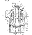
- a work support is structured as follows, for example, as shown in FIG. 6 .
- a work support includes: a housing 2; a support rod 5 supported by the housing 2 so as to be movable in an up-down direction and configured to be advanced/retracted relative to a workpiece W; an advance piston 14 including a piston portion 15 hermetically inserted in a tubular hole 13 in a lower portion of the housing 2 so as to be movable in the up-down direction; an advance-use pressure chamber 31 provided below the piston portion 15; a biasing means 18 configured to bias the support rod 5 upward; and a retracting means 19 configured to move the support rod 5 downward via the advance piston 14.
- the work support further includes: an ascent-detecting air supply port 33, a descent-detecting air supply port 43, and an air discharge port 44, which are provided to the housing 2; an air outlet 38 provided at a leading end portion of the support rod 5, the air outlet 38 being configured to be closed by the workpiece W; an ascent-detecting air passage 39 provided in the housing 2 and in the support rod 5, the ascent-detecting air passage 39 communicatively connecting the ascent-detecting air supply port 33 and the air outlet 38 to each other; a descent-detecting air passage 45 provided in the housing 2, the descent-detecting air passage 45 communicatively connecting the descent-detecting air supply port 43 and the air discharge port 44 to each other; and a valve mechanism 52 configured to close the descent-detecting air passage 45 when the advance piston 14 is retracted to a lowered position by the retracting means 19, the valve mechanism 52 including a closing surface 53 provided on an outer peripheral surface of the piston portion 15 and a to-be-closed surface 54 provided on an inner peripheral surface of the housing 2.
- the work support of the third aspect provides functions and effects similar to those of the work support of the first aspect.
- the closing surface 53 is provided on an outer peripheral surface of a flange portion 15a provided at an upper end portion of the piston portion 15; and the to-be-closed surface 54 is provided around an opening at a downstream end of an air passage 46, which is an element of the descent-detecting air passage 45 and extends from the descent-detecting air supply port 43.
- the closing surface 53 is configured to face onto the to-be-closed surface 54 when the advance piston 14 is retracted to the lowered position by the retracting means 19, and thereby the descent-detecting air passage 45 is closed.
- the biasing means 18 includes an advance spring 18 provided in a tubular hole 11 of the support rod 5, the advance spring 18 biasing the support rod 5 upward via the advance piston 14.
- a work support capable of distinguishing among the states: a retracted release state; a state in which a support rod does not ascend when driven for advancing and locking; and an advanced lock state.
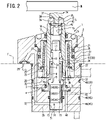
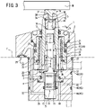
- FIG. 1 to FIG. 3 show a first embodiment of the present invention.
- the structure of a work support 1 of the first embodiment of the present invention will be described with reference to FIG. 1 to FIG. 3 .
- a housing 2 is attached to a stationary stand T such as a table.
- the housing 2 includes an upper end wall 2a, a lower end wall 2b, and a barrel portion 2c.
- a tubular central member 3 is provided at a central portion in a lower portion of the barrel portion 2c so as to extend upward.
- a lower flange 4 of the central member 3 is sandwiched between the lower end wall 2b and the barrel portion 2c and fixed to the lower end wall 2b and to the barrel portion 2c.
- the central member 3 is an element structuring the housing 2.
- a support rod 5 is supported by the housing 2 so as to be movable in the up-down direction.
- the support rod 5 includes: a tubular rod member 6 and an upper end block 7.
- the rod member 6 includes: a tapered hole 8; a first tubular hole 9 with a larger diameter; an inner peripheral step portion 10; and a second tubular hole 11 with a smaller diameter, which are provided in this order from a lower end portion to an upper end portion of the rod member 6.
- the upper end block 7 is screwed to an upper end portion of the second tubular hole 11.
- a rod seal 12 having a function of scraper is attached between an upper portion of the rod member 6 and the upper end wall 2a.
- a lower portion of the rod member 6 is fitted over the central member 3 with a predetermined gap between them.
- a piston portion 15 of an advance piston 14 is hermetically inserted in a tubular hole 13 of the lower end wall 2b of the housing 2 so as to be movable in the up-down direction.
- a rod portion 16 is provided to protrude upward from the piston portion 15.
- An engaged portion 17 provided at an upper portion of the rod portion 16 is configured to come into contact with the inner peripheral step portion 10 of the rod member 6 of the support rod 5 from above.
- An advance spring 18 biasing the support rod 5 upward via the advance piston 14 is provided in the second tubular hole 11 of the rod member 6.
- a retraction spring 19 biasing the advance piston 14 downward is provided between: a flange portion 15a provided at an upper end portion of the piston portion 15; and an upper end wall 3a of the central member 3. These springs are designed so that the biasing force of the retraction spring 19 is larger than the biasing force of the advance spring 18.
- a sleeve member 20 formed by a tubular collet is fitted over a gripped and held area A provided on an outer peripheral surface of the support rod 5.
- the sleeve member 20 includes: a tapered outer peripheral surface 21 tapering down upward; and a slit 22 extending in the up-down direction.
- the slit 22 allows the sleeve member 20 to decrease its diameter elastically.
- An annular transmission tool 23 is disposed on an outer peripheral side of the sleeve member 20.
- a tapered inner peripheral surface 24 of the transmission tool 23 is opposed from above to the tapered outer peripheral surface 21.
- a plurality of balls 25 are inserted in an annular tapered gap created between the tapered outer peripheral surface 21 and the tapered inner peripheral surface 24.
- a locking-use piston portion 26 is provided to protrude radially outward from the transmission tool 23.
- a locking actuation chamber 27 is provided above the locking-use piston portion 26, while a spring chamber 28 is provided below the locking-use piston portion 26.
- a lock port 29 is communicatively connected to the locking actuation chamber 27.
- a return spring 30 is attached in the spring chamber 28.
- An advance-use pressure chamber 31 provided below the piston portion 15 of the advance piston 14 is communicatively connected to the lock port 29 by a connection passage 32 provided in the lower end wall 2b and the barrel portion 2c of the housing 2.
- An ascent-detecting air supply port 33 to which pressurized air is supplied, is provided on a side surface of the barrel portion 2c.
- a through hole 7a extending in the up-down direction is provided through the upper end block 7 forming an upper end portion of the support rod 5.
- a rod portion 35 of a contact tool 34 is inserted in the through hole 7a so as to be movable up and down.
- a communication passage 36 of a groove-like shape is provided on an outer periphery of the rod portion 35 so as to extend in the up-down direction.
- An annular air outlet 38 is provided between: a large diameter portion 37 provided at an upper portion of the contact tool 34; and the upper end block 7. The contact tool 34 is retained to the upper end block 7 with a pin 42 to prevent the contact tool 34 from being pushed out by pressurized air.
- the ascent-detecting air supply port 33 is communicatively connected to the air outlet 38 by an ascent-detecting air passage 39.
- the ascent-detecting air passage 39 includes: an air passage 40 extending horizontally from the ascent-detecting air supply port 33 and provided in the barrel portion 2c; the spring chamber 28; the slit 22 of the sleeve member 20; the tapered hole 8 of the rod member 6 of the support rod 5; a gap between an inner peripheral surface of a lower half portion of the rod member 6 and an outer peripheral surface of the central member 3; a groove 41 provided at the inner peripheral step portion 10 of the rod member 6; the second tubular hole 11 of the rod member 6; the through hole 7a of the upper end block 7; and the communication passage 36 provided on the contact tool 34.
- the pressure of pressurized air supplied to the ascent-detecting air supply port 33 is detected by a pressure detection means, which is not illustrated.
- a descent-detecting air supply port 43 to which pressurized air is supplied is provided on a side surface of the lower end wall 2b.
- An air discharge port 44 is provided on an under surface of the lower end wall 2b.
- the descent-detecting air supply port 43 is communicatively connected to the air discharge port 44 by a descent-detecting air passage 45.
- a valve mechanism 49 is disposed in the descent-detecting air passage 45.
- the descent-detecting air passage 45 includes: an air passage 46 extending horizontally from the descent-detecting air supply port 43 and provided in the lower end wall 2b; a gap 47 between an outer peripheral surface of the piston portion 15 of the advance piston 14 and the tubular hole 13 of the lower end wall 2b; a tubular hole 3b of the central member 3 and a counterbore portion 3c below the tubular hole 3b; and an exhaust passage 48 provided in the lower end wall 2b and extending in the up-down direction.
- the pressure of pressurized air supplied to the descent-detecting air supply port 43 is detected by a pressure detection means, which is not illustrated.
- the valve mechanism 49 includes: a valve surface 50 provided on an under surface of the flange portion 15a of the piston portion 15; and a valve seat 51 provided on an inner bottom surface on the lower end wall 2b.
- the work support 1 operates as follows.
- the valve surface 50 is in contact with the valve seat 51, and thereby the descent-detecting air passage 45 is closed.
- the contact tool 34 has been raised by the pressure of pressurized air supplied to the ascent-detecting air supply port 33, and air comes out from the air outlet 38.
- a part of pressurized air supplied to the ascent-detecting air supply port 33 flows into the tubular hole 3b of the central member 3 through a small gap between an inner peripheral surface of the upper end wall 3a of the central member 3 and an outer peripheral surface of the rod portion 16 of the advance piston 14, and then the air is discharged from the air discharge port 44 via the exhaust passage 48.
- the space created by the groove 41 provided at the inner peripheral step portion 10 of the rod member 6 is sufficiently larger than the above-mentioned small gap, only a small amount of pressurized air is discharged from the air discharge port 44, and a large amount of pressurized air flows upward through the second tubular hole 11 of the rod member 6 and comes out from the air outlet 38.
- pressurized air comes out from the air outlet 38, and therefore the pressure of pressurized air supplied to the ascent-detecting air supply port 33 has decreased.
- a low pressure level is detected by the pressure detection means (not shown), which generates an "OFF" signal.
- the valve mechanism 49 is closed, the pressure of pressurized air supplied to the descent-detecting air supply port 43 has increased to a predetermined pressure.
- a high pressure level is detected by the pressure detection means (not shown), which generates an "ON" signal.
- a workpiece W (see FIGs. 2 and 3 ) is brought from above, and a body of the workpiece W is supported by a support table (not shown). Thereafter, pressurized oil is supplied to the lock port 29.
- the pressure in the advance-use pressure chamber 31 increases first, and this causes the advance piston 14 to ascend against the biasing force of the retraction spring 19. Simultaneously with this, the advance spring 18 raises the support rod 5. Due to this, the valve surface 50 provided on the under surface of the flange portion 15a of the piston portion 15 is separated from the valve seat 51 provided on the inner bottom surface on the lower end wall 2b, to open the valve mechanism 49.
- the contact tool 34 comes into contact with an under surface of the workpiece W as shown in FIG. 3 , and this closes the air outlet 38.
- the pressure in the locking actuation chamber 27 increases, and the transmission tool 23 is moved downward by the hydraulic force applied from the locking actuation chamber 27 to the locking-use piston portion 26.
- This causes the tapered inner peripheral surface 24 of the transmission tool 23 to smoothly engage onto the tapered outer peripheral surface 21 of the sleeve member 20 while rolling the balls 25, to contract the sleeve member 20.
- the sleeve member 20 pushes the gripped and held area A of the support rod 5 radially inward, so that the support rod 5 is gripped and held.
- a top surface of the workpiece W is machined in the above-described advanced lock state.
- a downward pushing force exerted to the workpiece W in the machining process is received by the support rod 5 of the work support 1.
- the air outlet 38 is closed, and this increases the pressure of pressurized air supplied to the ascent-detecting air supply port 33 to a predetermined pressure.
- a high pressure level is detected by the pressure detection means (not shown), which generates an "ON" signal.
- the valve mechanism 49 is open, the pressure of pressurized air supplied to the descent-detecting air supply port 43 has decreased.
- a low pressure level is detected by the pressure detection means (not shown), which generates an "OFF" signal.
- the device operates as follows.
- the pressure of pressurized air supplied to the ascent-detecting air supply port 33 remains low. Such a low pressure level is detected by the pressure detection means (not shown), which generates an "OFF" signal. Meanwhile, due to the pressurized oil supplied to the lock port 29, the advance piston 14 ascends even though the support rod 5 does not ascend. As a result, the valve mechanism 49 is opened and this decreases the pressure of pressurized air supplied to the descent-detecting air supply port 43. Such a low pressure level is detected by the pressure detection means (not shown), which generates an "OFF" signal.
- the respective signals output from the pressure detection means (not shown) for the pressurized air supplied to the ascent-detecting air supply port 33 and from the pressure detection means (not shown) for the pressurized air supplied to the descent-detecting air supply port 43 are as follows.
- the respective signals are "OFF" and "ON”.
- the respective signals are "OFF" and "OFF”.
- the respective signals are "ON" and "OFF”.
- the work support 1 is capable of distinguishing among the states: the retracted release state; the state in which the support rod 5 does not ascend when driven for advancing and locking; and the advanced lock state, based on the combinations of: the pressure level of the pressurized air supplied to the ascent-detecting air supply port 33; and the pressure level of the pressurized air supplied to the descent-detecting air supply port 43.
- the respective signals are "OFF” and “OFF”, both (i) in the state in which the support rod 5 does not ascend when driven for advancing and locking, and (ii) in the normal transition state shown in FIG. 2 , in which the support rod 5 ascends when driven for advancing and locking.
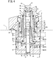
- FIG. 4 shows a second embodiment of the present invention.
- the second embodiment is different from the first embodiment in the following points.
- the air passage 46 extending horizontally from the descent-detecting air supply port 43 and provided in the lower end wall 2b is arranged to bend upward at its downstream-side end portion and to open onto an bottom surface on the lower end wall 2b.
- the air passage 46 is directly closed by the valve surface 50 provided on the under surface of the flange portion 15a of the piston portion 15, when the advance piston 14 is retracted to its lowered position. This makes it easier to close the descent-detecting air passage 45 than in the configuration of the first embodiment.
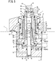
- FIG. 5 shows a third embodiment of the present invention.
- the third embodiment is different from the second embodiment in the following points.
- the work support 1 of the third embodiment includes no exhaust passage 48.
- the descent-detecting air passage 45 of this embodiment communicatively connects the descent-detecting air supply port 43 to the air outlet 38, and includes: the air passage 46 extending horizontally from the descent-detecting air supply port 43 and then bending upward, the air passage 46 being provided in the lower end wall 2b; the counterbore portion 3c and the tubular hole 3b of the central member 3; a gap between the upper end wall 3a of the central member 3 and the rod portion 16 of the advance piston 14; the groove 41 provided at the inner peripheral step portion 10 of the rod member 6; the second tubular hole 11 of the rod member 6; the through hole 7a of the upper end block 7; and the communication passage 36 provided on the contact tool 34.
- a portion of the ascent-detecting air passage 39 is shared with the descent-detecting air passage 45.
- the respective signals output from the pressure detection means (not shown) for the pressurized air supplied to the ascent-detecting air supply port 33 and from the pressure detection means (not shown) for the pressurized air supplied to the descent-detecting air supply port 43 are as follows.
- the respective signals are "OFF” and "ON”.
- the respective signals are "OFF" and "OFF”.
- the respective signals are "ON" and "ON”.
- the work support 1 of the third embodiment which has no exhaust passage 48, is also capable of distinguishing among the states: the retracted release state; the state in which the support rod 5 does not ascend when driven for advancing and locking; and the advanced lock state, based on the combinations of: the pressure level of the pressurized air supplied to the ascent-detecting air supply port 33; and the pressure level of the pressurized air supplied to the descent-detecting air supply port 43.
- FIG. 6 shows a fourth embodiment of the present invention.
- the fourth embodiment is different from the first embodiment in the following points.
- a closing surface 53 which is an element of a valve mechanism 52, is provided on an outer peripheral surface of the flange portion 15a provided at the upper end portion of the piston portion 15 of the advance piston 14. Furthermore, a to-be-closed surface 54, which is an element of the valve mechanism 52, is provided on an inner peripheral surface of a lower end portion of the lower flange 4 of the central member 3 of the housing 2.
- the to-be-closed surface 54 of the valve mechanism 52 is provided around an opening at a downstream end of the air passage 46 extending from the descent-detecting air supply port 43.
- the to-be-closed surface 54 is configured to face onto the closing surface 53 when the advance piston 14 is retracted to its lowered position.
- the opening at the downstream end of the air passage 46 is closed by the closing surface 53, and thereby the descent-detecting air passage 45 is closed.
- the closing surface 53 moves away from the to-be-closed surface 54, and this opens the descent-detecting air passage 45.
- an "ON" signal is output in response to a high pressure level of pressurized air and an “OFF” signal is output in response to a low pressure level of pressurized air.
- the device may be arranged so that an "OFF” signal is output in response to a high pressure level of pressurized air and an "ON” signal is output in response to a low pressure level of pressurized air.
- the flow rate of pressurized air may be used to detect the state of pressurized air.
- the flow rate of pressurized air increases when the air outlet 38 is open, and the flow rate increases when the valve mechanism 49 (or the valve mechanism 52) is open.
- the flow rate of pressurized air decreases when the air outlet 38 is closed; and the flow rate decreases when the valve mechanism 49 (or the valve mechanism 52) is closed.
- the support rod 5 is biased upward not only by the biasing force of the advance spring 18, but also by the biasing force of pressurized air supplied to the ascent-detecting air supply port 33. That is, in each of the above embodiments, the advance spring 18 and the pressurized air supplied to the ascent-detecting air supply port 33 are used as a biasing means configured to bias the support rod 5 upward. Instead of this, only the pressurized air supplied to the ascent-detecting air supply port 33 may be used as the biasing means configured to bias the support rod 5 upward, without providing the advance spring 18.
- the retraction spring 19 is used as a retracting means configured to move the support rod downward via the advance piston 14.
- the retracting means may be constituted by: a pressure chamber, which is provided in an internal space of the central member 3 using a sealing member such as an O ring while keeping the communication between the air passage 46 and the exhaust passage 48 via the valve mechanism 49 (or the valve mechanism 52); and releasing-use pressure fluid such as pressurized oil and compressed air supplied to the pressure chamber.
- the sleeve member 20 may be structured by a thin sleeve, instead of a collet.
Landscapes
- Engineering & Computer Science (AREA)
- Mechanical Engineering (AREA)
- Actuator (AREA)
- Jigs For Machine Tools (AREA)
Claims (7)
- Werkstückhalterung, umfassend:Ein Gehäuse (2);eine Stützstange (5), die vom Gehäuse (2) gestützt wird, um in einer Hoch-Runter-Richtung beweglich zu sein und konfiguriert zu sein, um relativ zu einem Werkstück (W) vorgeschoben/zurückgezogen zu werden;einen Vorschubkolben (14) einschließlich eines Kolbenabschnitts (15), der hermetisch in ein röhrenförmiges Loch (13) in einem unteren Abschnitt des Gehäuses (2) eingefügt ist, um in der Hoch-Runter-Richtung beweglich zu sein;eine Vorschub verwendende Druckkammer (31), die unterhalb des Kolbenabschnitts (15) bereitgestellt ist;ein Vorspannmittel (18), das konfiguriert ist, die Stützstange (5) aufwärts vorzuspannen; undEin Rückzugsmittel (19), das konfiguriert ist, die Stützstange (5) über den Vorschubkolben (14) abwärtszubewegen,wobei die Werkstückhalterung ferner umfasst:Eine Aufstieg erkennende Luftzufuhröffnung (33), eine Abstieg erkennende Luftzufuhröffnung (43), und eine Luftaustrittsöffnung (44), die dem Gehäuse (2) bereitgestellt sind;einen Luftauslass (38), der an einem vorderen Endabschnitt der Stützstange (5) bereitgestellt ist, wobei der Luftauslass (38) konfiguriert ist, vom Werkstück (W) geschlossen zu werden;einen Aufstieg erkennenden Luftdurchgang (39), der im Gehäuse (2) und in der Stützstange (5) bereitgestellt ist, wobei der Aufstieg erkennende Luftdurchgang (39) die Aufstieg erkennende Luftzufuhröffnung (33) und den Luftauslass (38) kommunikativ miteinander verbindet;einen Abstieg erkennenden Luftdurchgang (45), der im Gehäuse (2) bereitgestellt ist, wobei der Abstieg erkennende Luftdurchgang (45) die Abstieg erkennende Luftzufuhröffnung (43) und die Luftaustrittsöffnung (44) kommunikativ miteinander verbindet; undeinen Ventilmechanismus (49), der konfiguriert ist, den Abstieg erkennenden Luftdurchgang (45) zu schließen, wenn der Vorschubkolben (14) vom Rückzugsmittel (19) in eine abgesenkte Position zurückgezogen wird, wobei der Ventilmechanismus (49) eine Ventiloberfläche (50), die am Kolbenabschnitt (15) bereitgestellt ist und einen Ventilsitz (51) einschließt, der an einer Innenfläche des Gehäuses (2) bereitgestellt ist.
- Werkstückhalterung, umfassend:Ein Gehäuse (2);eine Stützstange (5), die vom Gehäuse (2) gestützt wird, um in einer Hoch-Runter-Richtung beweglich zu sein und konfiguriert zu sein, um relativ zu einem Werkstück (W) vorgeschoben/zurückgezogen zu werden;einen Vorschubkolben (14) einschließlich eines Kolbenabschnitts (15), der hermetisch in ein röhrenförmiges Loch (13) in einem unteren Abschnitt des Gehäuses (2) eingefügt ist, um in der Hoch-Runter-Richtung beweglich zu sein;eine Vorschub verwendende Druckkammer (31), die unterhalb des Kolbenabschnitts (15) bereitgestellt ist;ein Vorspannmittel (18), das konfiguriert ist, die Stützstange (5) aufwärts vorzuspannen; undEin Rückzugsmittel (19), das konfiguriert ist, die Stützstange (5) über den Vorschubkolben (14) abwärtszubewegen,wobei die Werkstückhalterung ferner umfasst:Eine Aufstieg erkennende Luftzufuhröffnung (33) und eine Abstieg erkennende Luftzufuhröffnung (43), die dem Gehäuse (2) bereitgestellt sind;einen Luftauslass (38), der an einem vorderen Endabschnitt der Stützstange (5) bereitgestellt ist, wobei der Luftauslass (38) konfiguriert ist, vom Werkstück (W) geschlossen zu werden;einen Aufstieg erkennenden Luftdurchgang (39), der im Gehäuse (2) und in der Stützstange (5) bereitgestellt ist, wobei der Aufstieg erkennende Luftdurchgang (39) die Aufstieg erkennende Luftzufuhröffnung (33) und den Luftauslass (38) kommunikativ miteinander verbindet;einen Abstieg erkennenden Luftdurchgang (45), der im Gehäuse (2) und in der Stützstange (5) bereitgestellt ist, wobei der Abstieg erkennende Luftdurchgang (45) die Abstieg erkennende Luftzufuhröffnung (43) und den Luftauslass (38) kommunikativ miteinander verbindet; undeinen Ventilmechanismus (49), der konfiguriert ist, den Abstieg erkennenden Luftdurchgang (45) zu schließen, wenn der Vorschubkolben (14) vom Rückzugsmittel (19) in eine abgesenkte Position zurückgezogen wird, wobei der Ventilmechanismus (49) eine Ventiloberfläche (50), die am Kolbenabschnitt (15) bereitgestellt ist und einen Ventilsitz (51) einschließt, der an einer Innenfläche des Gehäuses (2) bereitgestellt ist.
- Werkstückhalterung nach Anspruch 1 oder 2, wobei:Die Ventiloberfläche (50) auf einer Unterseite eines Flanschabschnitts (15a) bereitgestellt ist, der an einem oberen Endabschnitt des Kolbenabschnitts (15) bereitgestellt ist;der Ventilsitz (51) auf einer inneren Bodenfläche des Gehäuses (2) bereitgestellt ist; unddie Ventiloberfläche (50) konfiguriert ist, in Kontakt mit dem Ventilsitz (51) zu kommen, wenn der Vorschubkolben (14) vom Rückzugsmittel (19) in die abgesenkte Position zurückgezogen wird, und dadurch der Abstieg erkennende Luftdurchgang (45) geschlossen wird.
- Werkstückhalterung nach Anspruch 3. wobei
das Rückzugsmittel (19) eine im Gehäuse (2) bereitgestellte Rückzugsfeder (19) ist, wobei die Rückzugsfeder (19) in Kontakt mit einer Oberseite des Flanschabschnitts (15a) ist und den Vorschubkolben (14) abwärts vorspannt. - Werkstückhalterung, umfassend:Ein Gehäuse (2);eine Stützstange (5), die vom Gehäuse (2) gestützt wird, um in einer Hoch-Runter-Richtung beweglich zu sein und konfiguriert zu sein, um relativ zu einem Werkstück (W) vorgeschoben/zurückgezogen zu werden;einen Vorschubkolben (14) einschließlich eines Kolbenabschnitts (15), der hermetisch in ein röhrenförmiges Loch (13) in einem unteren Abschnitt des Gehäuses (2) eingefügt ist, um in der Hoch-Runter-Richtung beweglich zu sein;eine Vorschub verwendende Druckkammer (31), die unterhalb des Kolbenabschnitts (15) bereitgestellt ist;ein Vorspannmittel (18), das konfiguriert ist, die Stützstange (5) aufwärts vorzuspannen; undein Rückzugsmittel (19), das konfiguriert ist, die Stützstange (5) über den Vorschubkolben (14) abwärtszubewegen,wobei die Werkstückhalterung ferner umfasst:Eine Aufstieg erkennende Luftzufuhröffnung (33), eine Abstieg erkennende Luftzufuhröffnung (43), und eine Luftaustrittsöffnung (44), die dem Gehäuse (2) bereitgestellt sind;einen Luftauslass (38), der an einem vorderen Endabschnitt der Stützstange (5) bereitgestellt ist, wobei der Luftauslass (38) konfiguriert ist, vom Werkstück (W) geschlossen zu werden;einen Aufstieg erkennenden Luftdurchgang (39), der im Gehäuse (2) und in der Stützstange (5) bereitgestellt ist, wobei der Aufstieg erkennende Luftdurchgang (39) die Aufstieg erkennende Luftzufuhröffnung (33) und den Luftauslass (38) kommunikativ miteinander verbindet;einen Abstieg erkennenden Luftdurchgang (45), der im Gehäuse (2) bereitgestellt ist, wobei der Abstieg erkennende Luftdurchgang (45) die Abstieg erkennende Luftzufuhröffnung (43) und die Luftaustrittsöffnung (44) kommunikativ miteinander verbindet; undeinen Ventilmechanismus (52), der konfiguriert ist, den Abstieg erkennenden Luftdurchgang (45) zu schließen, wenn der Vorschubkolben (14) vom Rückzugsmittel (19) in eine abgesenkte Position zurückgezogen wird, wobei der Ventilmechanismus (52) eine schließende Oberfläche (53), die an einer äußeren peripheren Oberfläche des Kolbenabschnitts (15) bereitgestellt ist und eine zu schließende Oberfläche (54) einschließt, die an einer inneren peripheren Oberfläche des Gehäuses (2) bereitgestellt ist.
- Werkstückhalterung nach Anspruch 5, wobei:Die schließende Oberfläche (53) an einer äußeren peripheren Oberfläche des Flanschabschnitts (15a) bereitgestellt ist, der an einem oberen Endabschnitt des Kolbenabschnitts (15) bereitgestellt ist;die zu schließende Oberfläche (54) um eine Öffnung an einem stromabwärts gelegenen Ende eines Luftdurchgangs (46) herum bereitgestellt ist, welcher ein Element des Abstieg erkennenden Luftdurchgangs (45) ist und sich aus der Abstieg erkennenden Luftzufuhröffnung (43) erstreckt; unddie schließende Oberfläche (53) konfiguriert ist, auf die zu schließende Oberfläche (54) zugewandt zu sein, wenn der Vorschubkolben (14) vom Rückzugsmittel (19) in die abgesenkte Position zurückgezogen wird, und dadurch der Abstieg erkennende Luftdurchgang (45) geschlossen wird.
- Werkstückhalterung nach irgendeinem der Ansprüche 1 bis 6, wobei das Vorspannmittel (18) eine Vorschubfeder (18) einschließt, die in einem röhrenförmigen Loch (11) der Stützstange (5) bereitgestellt ist, wobei die Vorschubfeder (18) die Stützstange (5) über den Vorschubkolben (14) aufwärts vorspannt.
Applications Claiming Priority (2)
| Application Number | Priority Date | Filing Date | Title |
|---|---|---|---|
| JP2018198194A JP7193122B2 (ja) | 2018-10-22 | 2018-10-22 | ワークサポート |
| PCT/JP2019/040320 WO2020085130A1 (ja) | 2018-10-22 | 2019-10-11 | ワークサポート |
Publications (3)
| Publication Number | Publication Date |
|---|---|
| EP3815841A1 EP3815841A1 (de) | 2021-05-05 |
| EP3815841A4 EP3815841A4 (de) | 2021-11-10 |
| EP3815841B1 true EP3815841B1 (de) | 2022-07-06 |
Family
ID=70331934
Family Applications (1)
| Application Number | Title | Priority Date | Filing Date |
|---|---|---|---|
| EP19876254.4A Active EP3815841B1 (de) | 2018-10-22 | 2019-10-11 | Werkstückhalterung |
Country Status (6)
| Country | Link |
|---|---|
| US (1) | US11628527B2 (de) |
| EP (1) | EP3815841B1 (de) |
| JP (1) | JP7193122B2 (de) |
| KR (1) | KR102414133B1 (de) |
| CN (1) | CN112805115B (de) |
| WO (1) | WO2020085130A1 (de) |
Cited By (1)
| Publication number | Priority date | Publication date | Assignee | Title |
|---|---|---|---|---|
| DE102022119899A1 (de) | 2022-08-08 | 2024-02-08 | Frank Entzmann | Vorrichtung zur Abstützung eines zu bearbeitenden Werkstücks |
Families Citing this family (1)
| Publication number | Priority date | Publication date | Assignee | Title |
|---|---|---|---|---|
| CN118456078B (zh) * | 2024-07-15 | 2024-09-10 | 北京智同精密传动科技有限责任公司 | 一种液压夹紧机构及其使用方法 |
Family Cites Families (14)
| Publication number | Priority date | Publication date | Assignee | Title |
|---|---|---|---|---|
| JP3617745B2 (ja) * | 1996-11-12 | 2005-02-09 | 株式会社コスメック | コレット式クランプ |
| JP4562832B2 (ja) * | 1999-09-28 | 2010-10-13 | 株式会社コスメック | 搬入物の検出装置 |
| DE202004007738U1 (de) * | 2004-05-11 | 2004-07-22 | Drumag Gmbh Fluidtechnik | Druckmediumzylinder |
| JP4302174B1 (ja) | 2008-02-15 | 2009-07-22 | パスカルエンジニアリング株式会社 | クランプ装置 |
| US8444128B2 (en) * | 2008-09-04 | 2013-05-21 | Vektek, Inc. | Double acting work support with internal sequence control |
| DE102008052270B4 (de) * | 2008-10-18 | 2018-11-29 | Andreas Maier Gmbh & Co. Kg | Schnellspannzylinder mit Anwesenheitskontrolle des Einzugsnippels |
| JP5541786B2 (ja) * | 2010-05-10 | 2014-07-09 | パスカルエンジニアリング株式会社 | クランプ装置 |
| JP5557630B2 (ja) | 2010-07-13 | 2014-07-23 | パスカルエンジニアリング株式会社 | クランプ装置 |
| JP5534451B2 (ja) * | 2010-10-25 | 2014-07-02 | 株式会社コスメック | ワークサポート |
| JP2012166276A (ja) * | 2011-02-10 | 2012-09-06 | Pascal Engineering Corp | クランプ装置のロッド位置検出装置 |
| JP5337221B2 (ja) * | 2011-10-07 | 2013-11-06 | パスカルエンジニアリング株式会社 | 流体圧シリンダ及びクランプ装置 |
| JP5859596B2 (ja) * | 2014-04-17 | 2016-02-10 | 株式会社コスメック | ワークサポート |
| JP6410342B2 (ja) | 2014-06-04 | 2018-10-24 | パスカルエンジニアリング株式会社 | 流体圧シリンダ及びクランプ装置 |
| JP6552310B2 (ja) * | 2015-06-26 | 2019-07-31 | 株式会社コスメック | シリンダ装置 |
-
2018
- 2018-10-22 JP JP2018198194A patent/JP7193122B2/ja active Active
-
2019
- 2019-10-11 US US17/267,824 patent/US11628527B2/en active Active
- 2019-10-11 WO PCT/JP2019/040320 patent/WO2020085130A1/ja not_active Ceased
- 2019-10-11 EP EP19876254.4A patent/EP3815841B1/de active Active
- 2019-10-11 KR KR1020217004861A patent/KR102414133B1/ko active Active
- 2019-10-11 CN CN201980064924.9A patent/CN112805115B/zh active Active
Cited By (1)
| Publication number | Priority date | Publication date | Assignee | Title |
|---|---|---|---|---|
| DE102022119899A1 (de) | 2022-08-08 | 2024-02-08 | Frank Entzmann | Vorrichtung zur Abstützung eines zu bearbeitenden Werkstücks |
Also Published As
| Publication number | Publication date |
|---|---|
| US20210187678A1 (en) | 2021-06-24 |
| JP7193122B2 (ja) | 2022-12-20 |
| JP2020066063A (ja) | 2020-04-30 |
| EP3815841A1 (de) | 2021-05-05 |
| EP3815841A4 (de) | 2021-11-10 |
| CN112805115A (zh) | 2021-05-14 |
| US11628527B2 (en) | 2023-04-18 |
| KR20210031962A (ko) | 2021-03-23 |
| CN112805115B (zh) | 2022-10-21 |
| KR102414133B1 (ko) | 2022-06-28 |
| WO2020085130A1 (ja) | 2020-04-30 |
Similar Documents
| Publication | Publication Date | Title |
|---|---|---|
| US3749122A (en) | System for installing fluid elements in conduit circuits | |
| EP2868430B1 (de) | Spannvorrichtung | |
| US8444128B2 (en) | Double acting work support with internal sequence control | |
| US12134157B2 (en) | Clamping apparatus | |
| EP3815841B1 (de) | Werkstückhalterung | |
| US7231986B2 (en) | Well tool protection system and method | |
| EP3660367B1 (de) | Zylindervorrichtung mit einem zuschaltventil | |
| KR200496444Y1 (ko) | 워크 서포트 | |
| NO20240625A1 (en) | Shifting sleeve with extrudable ball and dog | |
| JP5534451B2 (ja) | ワークサポート | |
| EP3991912B1 (de) | Werkstückabstützvorrichtung | |
| JP5859596B2 (ja) | ワークサポート | |
| US12115615B2 (en) | Work support | |
| US20050230651A1 (en) | Protection of a seal element | |
| JP4562832B2 (ja) | 搬入物の検出装置 | |
| JP2017154212A (ja) | 動作検出機能付き位置決め装置 | |
| EP4421363B1 (de) | Rückschlagventilvorrichtung | |
| JPH08266681A (ja) | 乾式型閉鎖スプリンクラーヘッド | |
| JP6064077B1 (ja) | 塗布装置 | |
| CN109469659B (zh) | 一种单向顺序阀 | |
| CN118742413A (zh) | 夹紧装置 |
Legal Events
| Date | Code | Title | Description |
|---|---|---|---|
| STAA | Information on the status of an ep patent application or granted ep patent |
Free format text: STATUS: THE INTERNATIONAL PUBLICATION HAS BEEN MADE |
|
| PUAI | Public reference made under article 153(3) epc to a published international application that has entered the european phase |
Free format text: ORIGINAL CODE: 0009012 |
|
| STAA | Information on the status of an ep patent application or granted ep patent |
Free format text: STATUS: REQUEST FOR EXAMINATION WAS MADE |
|
| 17P | Request for examination filed |
Effective date: 20210201 |
|
| AK | Designated contracting states |
Kind code of ref document: A1 Designated state(s): AL AT BE BG CH CY CZ DE DK EE ES FI FR GB GR HR HU IE IS IT LI LT LU LV MC MK MT NL NO PL PT RO RS SE SI SK SM TR |
|
| A4 | Supplementary search report drawn up and despatched |
Effective date: 20211012 |
|
| RIC1 | Information provided on ipc code assigned before grant |
Ipc: B23Q 17/00 20060101ALI20211006BHEP Ipc: B23Q 3/06 20060101AFI20211006BHEP |
|
| DAV | Request for validation of the european patent (deleted) | ||
| DAX | Request for extension of the european patent (deleted) | ||
| GRAP | Despatch of communication of intention to grant a patent |
Free format text: ORIGINAL CODE: EPIDOSNIGR1 |
|
| STAA | Information on the status of an ep patent application or granted ep patent |
Free format text: STATUS: GRANT OF PATENT IS INTENDED |
|
| INTG | Intention to grant announced |
Effective date: 20220322 |
|
| GRAS | Grant fee paid |
Free format text: ORIGINAL CODE: EPIDOSNIGR3 |
|
| GRAA | (expected) grant |
Free format text: ORIGINAL CODE: 0009210 |
|
| STAA | Information on the status of an ep patent application or granted ep patent |
Free format text: STATUS: THE PATENT HAS BEEN GRANTED |
|
| AK | Designated contracting states |
Kind code of ref document: B1 Designated state(s): AL AT BE BG CH CY CZ DE DK EE ES FI FR GB GR HR HU IE IS IT LI LT LU LV MC MK MT NL NO PL PT RO RS SE SI SK SM TR |
|
| REG | Reference to a national code |
Ref country code: AT Ref legal event code: REF Ref document number: 1502528 Country of ref document: AT Kind code of ref document: T Effective date: 20220715 Ref country code: CH Ref legal event code: EP |
|
| REG | Reference to a national code |
Ref country code: DE Ref legal event code: R096 Ref document number: 602019016847 Country of ref document: DE |
|
| REG | Reference to a national code |
Ref country code: IE Ref legal event code: FG4D |
|
| REG | Reference to a national code |
Ref country code: LT Ref legal event code: MG9D |
|
| REG | Reference to a national code |
Ref country code: NL Ref legal event code: MP Effective date: 20220706 |
|
| PG25 | Lapsed in a contracting state [announced via postgrant information from national office to epo] |
Ref country code: SE Free format text: LAPSE BECAUSE OF FAILURE TO SUBMIT A TRANSLATION OF THE DESCRIPTION OR TO PAY THE FEE WITHIN THE PRESCRIBED TIME-LIMIT Effective date: 20220706 Ref country code: RS Free format text: LAPSE BECAUSE OF FAILURE TO SUBMIT A TRANSLATION OF THE DESCRIPTION OR TO PAY THE FEE WITHIN THE PRESCRIBED TIME-LIMIT Effective date: 20220706 Ref country code: PT Free format text: LAPSE BECAUSE OF FAILURE TO SUBMIT A TRANSLATION OF THE DESCRIPTION OR TO PAY THE FEE WITHIN THE PRESCRIBED TIME-LIMIT Effective date: 20221107 Ref country code: NO Free format text: LAPSE BECAUSE OF FAILURE TO SUBMIT A TRANSLATION OF THE DESCRIPTION OR TO PAY THE FEE WITHIN THE PRESCRIBED TIME-LIMIT Effective date: 20221006 Ref country code: NL Free format text: LAPSE BECAUSE OF FAILURE TO SUBMIT A TRANSLATION OF THE DESCRIPTION OR TO PAY THE FEE WITHIN THE PRESCRIBED TIME-LIMIT Effective date: 20220706 Ref country code: LV Free format text: LAPSE BECAUSE OF FAILURE TO SUBMIT A TRANSLATION OF THE DESCRIPTION OR TO PAY THE FEE WITHIN THE PRESCRIBED TIME-LIMIT Effective date: 20220706 Ref country code: LT Free format text: LAPSE BECAUSE OF FAILURE TO SUBMIT A TRANSLATION OF THE DESCRIPTION OR TO PAY THE FEE WITHIN THE PRESCRIBED TIME-LIMIT Effective date: 20220706 Ref country code: FI Free format text: LAPSE BECAUSE OF FAILURE TO SUBMIT A TRANSLATION OF THE DESCRIPTION OR TO PAY THE FEE WITHIN THE PRESCRIBED TIME-LIMIT Effective date: 20220706 Ref country code: ES Free format text: LAPSE BECAUSE OF FAILURE TO SUBMIT A TRANSLATION OF THE DESCRIPTION OR TO PAY THE FEE WITHIN THE PRESCRIBED TIME-LIMIT Effective date: 20220706 |
|
| REG | Reference to a national code |
Ref country code: AT Ref legal event code: MK05 Ref document number: 1502528 Country of ref document: AT Kind code of ref document: T Effective date: 20220706 |
|
| PG25 | Lapsed in a contracting state [announced via postgrant information from national office to epo] |
Ref country code: PL Free format text: LAPSE BECAUSE OF FAILURE TO SUBMIT A TRANSLATION OF THE DESCRIPTION OR TO PAY THE FEE WITHIN THE PRESCRIBED TIME-LIMIT Effective date: 20220706 Ref country code: IS Free format text: LAPSE BECAUSE OF FAILURE TO SUBMIT A TRANSLATION OF THE DESCRIPTION OR TO PAY THE FEE WITHIN THE PRESCRIBED TIME-LIMIT Effective date: 20221106 Ref country code: HR Free format text: LAPSE BECAUSE OF FAILURE TO SUBMIT A TRANSLATION OF THE DESCRIPTION OR TO PAY THE FEE WITHIN THE PRESCRIBED TIME-LIMIT Effective date: 20220706 Ref country code: GR Free format text: LAPSE BECAUSE OF FAILURE TO SUBMIT A TRANSLATION OF THE DESCRIPTION OR TO PAY THE FEE WITHIN THE PRESCRIBED TIME-LIMIT Effective date: 20221007 |
|
| REG | Reference to a national code |
Ref country code: DE Ref legal event code: R097 Ref document number: 602019016847 Country of ref document: DE |
|
| PG25 | Lapsed in a contracting state [announced via postgrant information from national office to epo] |
Ref country code: SM Free format text: LAPSE BECAUSE OF FAILURE TO SUBMIT A TRANSLATION OF THE DESCRIPTION OR TO PAY THE FEE WITHIN THE PRESCRIBED TIME-LIMIT Effective date: 20220706 Ref country code: RO Free format text: LAPSE BECAUSE OF FAILURE TO SUBMIT A TRANSLATION OF THE DESCRIPTION OR TO PAY THE FEE WITHIN THE PRESCRIBED TIME-LIMIT Effective date: 20220706 Ref country code: DK Free format text: LAPSE BECAUSE OF FAILURE TO SUBMIT A TRANSLATION OF THE DESCRIPTION OR TO PAY THE FEE WITHIN THE PRESCRIBED TIME-LIMIT Effective date: 20220706 Ref country code: CZ Free format text: LAPSE BECAUSE OF FAILURE TO SUBMIT A TRANSLATION OF THE DESCRIPTION OR TO PAY THE FEE WITHIN THE PRESCRIBED TIME-LIMIT Effective date: 20220706 Ref country code: AT Free format text: LAPSE BECAUSE OF FAILURE TO SUBMIT A TRANSLATION OF THE DESCRIPTION OR TO PAY THE FEE WITHIN THE PRESCRIBED TIME-LIMIT Effective date: 20220706 |
|
| PLBE | No opposition filed within time limit |
Free format text: ORIGINAL CODE: 0009261 |
|
| STAA | Information on the status of an ep patent application or granted ep patent |
Free format text: STATUS: NO OPPOSITION FILED WITHIN TIME LIMIT |
|
| PG25 | Lapsed in a contracting state [announced via postgrant information from national office to epo] |
Ref country code: SK Free format text: LAPSE BECAUSE OF FAILURE TO SUBMIT A TRANSLATION OF THE DESCRIPTION OR TO PAY THE FEE WITHIN THE PRESCRIBED TIME-LIMIT Effective date: 20220706 Ref country code: MC Free format text: LAPSE BECAUSE OF FAILURE TO SUBMIT A TRANSLATION OF THE DESCRIPTION OR TO PAY THE FEE WITHIN THE PRESCRIBED TIME-LIMIT Effective date: 20220706 Ref country code: EE Free format text: LAPSE BECAUSE OF FAILURE TO SUBMIT A TRANSLATION OF THE DESCRIPTION OR TO PAY THE FEE WITHIN THE PRESCRIBED TIME-LIMIT Effective date: 20220706 |
|
| REG | Reference to a national code |
Ref country code: CH Ref legal event code: PL |
|
| 26N | No opposition filed |
Effective date: 20230411 |
|
| P01 | Opt-out of the competence of the unified patent court (upc) registered |
Effective date: 20230404 |
|
| REG | Reference to a national code |
Ref country code: BE Ref legal event code: MM Effective date: 20221031 |
|
| PG25 | Lapsed in a contracting state [announced via postgrant information from national office to epo] |
Ref country code: LU Free format text: LAPSE BECAUSE OF NON-PAYMENT OF DUE FEES Effective date: 20221011 Ref country code: AL Free format text: LAPSE BECAUSE OF FAILURE TO SUBMIT A TRANSLATION OF THE DESCRIPTION OR TO PAY THE FEE WITHIN THE PRESCRIBED TIME-LIMIT Effective date: 20220706 |
|
| PG25 | Lapsed in a contracting state [announced via postgrant information from national office to epo] |
Ref country code: LI Free format text: LAPSE BECAUSE OF NON-PAYMENT OF DUE FEES Effective date: 20221031 Ref country code: CH Free format text: LAPSE BECAUSE OF NON-PAYMENT OF DUE FEES Effective date: 20221031 |
|
| PG25 | Lapsed in a contracting state [announced via postgrant information from national office to epo] |
Ref country code: SI Free format text: LAPSE BECAUSE OF FAILURE TO SUBMIT A TRANSLATION OF THE DESCRIPTION OR TO PAY THE FEE WITHIN THE PRESCRIBED TIME-LIMIT Effective date: 20220706 |
|
| PG25 | Lapsed in a contracting state [announced via postgrant information from national office to epo] |
Ref country code: BE Free format text: LAPSE BECAUSE OF NON-PAYMENT OF DUE FEES Effective date: 20221031 |
|
| PG25 | Lapsed in a contracting state [announced via postgrant information from national office to epo] |
Ref country code: IE Free format text: LAPSE BECAUSE OF NON-PAYMENT OF DUE FEES Effective date: 20221011 |
|
| PG25 | Lapsed in a contracting state [announced via postgrant information from national office to epo] |
Ref country code: CY Free format text: LAPSE BECAUSE OF FAILURE TO SUBMIT A TRANSLATION OF THE DESCRIPTION OR TO PAY THE FEE WITHIN THE PRESCRIBED TIME-LIMIT Effective date: 20220706 |
|
| PG25 | Lapsed in a contracting state [announced via postgrant information from national office to epo] |
Ref country code: MK Free format text: LAPSE BECAUSE OF FAILURE TO SUBMIT A TRANSLATION OF THE DESCRIPTION OR TO PAY THE FEE WITHIN THE PRESCRIBED TIME-LIMIT Effective date: 20220706 Ref country code: HU Free format text: LAPSE BECAUSE OF FAILURE TO SUBMIT A TRANSLATION OF THE DESCRIPTION OR TO PAY THE FEE WITHIN THE PRESCRIBED TIME-LIMIT; INVALID AB INITIO Effective date: 20191011 |
|
| PG25 | Lapsed in a contracting state [announced via postgrant information from national office to epo] |
Ref country code: TR Free format text: LAPSE BECAUSE OF FAILURE TO SUBMIT A TRANSLATION OF THE DESCRIPTION OR TO PAY THE FEE WITHIN THE PRESCRIBED TIME-LIMIT Effective date: 20220706 |
|
| PG25 | Lapsed in a contracting state [announced via postgrant information from national office to epo] |
Ref country code: BG Free format text: LAPSE BECAUSE OF FAILURE TO SUBMIT A TRANSLATION OF THE DESCRIPTION OR TO PAY THE FEE WITHIN THE PRESCRIBED TIME-LIMIT Effective date: 20220706 |
|
| PG25 | Lapsed in a contracting state [announced via postgrant information from national office to epo] |
Ref country code: MT Free format text: LAPSE BECAUSE OF FAILURE TO SUBMIT A TRANSLATION OF THE DESCRIPTION OR TO PAY THE FEE WITHIN THE PRESCRIBED TIME-LIMIT Effective date: 20220706 |
|
| PGFP | Annual fee paid to national office [announced via postgrant information from national office to epo] |
Ref country code: DE Payment date: 20251021 Year of fee payment: 7 |
|
| PGFP | Annual fee paid to national office [announced via postgrant information from national office to epo] |
Ref country code: GB Payment date: 20251022 Year of fee payment: 7 |
|
| PGFP | Annual fee paid to national office [announced via postgrant information from national office to epo] |
Ref country code: IT Payment date: 20251024 Year of fee payment: 7 |
|
| PGFP | Annual fee paid to national office [announced via postgrant information from national office to epo] |
Ref country code: FR Payment date: 20251030 Year of fee payment: 7 |