EP3816656B1 - Procédé et dispositif de mesure optique de distance - Google Patents
Procédé et dispositif de mesure optique de distance Download PDFInfo
- Publication number
- EP3816656B1 EP3816656B1 EP20204308.9A EP20204308A EP3816656B1 EP 3816656 B1 EP3816656 B1 EP 3816656B1 EP 20204308 A EP20204308 A EP 20204308A EP 3816656 B1 EP3816656 B1 EP 3816656B1
- Authority
- EP
- European Patent Office
- Prior art keywords
- measuring
- interval
- measurement
- pulses
- pulse
- Prior art date
- Legal status (The legal status is an assumption and is not a legal conclusion. Google has not performed a legal analysis and makes no representation as to the accuracy of the status listed.)
- Active
Links
Images

Classifications
-
- G—PHYSICS
- G01—MEASURING; TESTING
- G01S—RADIO DIRECTION-FINDING; RADIO NAVIGATION; DETERMINING DISTANCE OR VELOCITY BY USE OF RADIO WAVES; LOCATING OR PRESENCE-DETECTING BY USE OF THE REFLECTION OR RERADIATION OF RADIO WAVES; ANALOGOUS ARRANGEMENTS USING OTHER WAVES
- G01S7/00—Details of systems according to groups G01S13/00, G01S15/00, G01S17/00
- G01S7/48—Details of systems according to groups G01S13/00, G01S15/00, G01S17/00 of systems according to group G01S17/00
- G01S7/4808—Evaluating distance, position or velocity data
-
- G—PHYSICS
- G01—MEASURING; TESTING
- G01S—RADIO DIRECTION-FINDING; RADIO NAVIGATION; DETERMINING DISTANCE OR VELOCITY BY USE OF RADIO WAVES; LOCATING OR PRESENCE-DETECTING BY USE OF THE REFLECTION OR RERADIATION OF RADIO WAVES; ANALOGOUS ARRANGEMENTS USING OTHER WAVES
- G01S17/00—Systems using the reflection or reradiation of electromagnetic waves other than radio waves, e.g. lidar systems
- G01S17/02—Systems using the reflection of electromagnetic waves other than radio waves
- G01S17/06—Systems determining position data of a target
- G01S17/08—Systems determining position data of a target for measuring distance only
- G01S17/10—Systems determining position data of a target for measuring distance only using transmission of interrupted, pulse-modulated waves
-
- G—PHYSICS
- G01—MEASURING; TESTING
- G01S—RADIO DIRECTION-FINDING; RADIO NAVIGATION; DETERMINING DISTANCE OR VELOCITY BY USE OF RADIO WAVES; LOCATING OR PRESENCE-DETECTING BY USE OF THE REFLECTION OR RERADIATION OF RADIO WAVES; ANALOGOUS ARRANGEMENTS USING OTHER WAVES
- G01S17/00—Systems using the reflection or reradiation of electromagnetic waves other than radio waves, e.g. lidar systems
- G01S17/02—Systems using the reflection of electromagnetic waves other than radio waves
- G01S17/06—Systems determining position data of a target
- G01S17/42—Simultaneous measurement of distance and other co-ordinates
-
- G—PHYSICS
- G01—MEASURING; TESTING
- G01S—RADIO DIRECTION-FINDING; RADIO NAVIGATION; DETERMINING DISTANCE OR VELOCITY BY USE OF RADIO WAVES; LOCATING OR PRESENCE-DETECTING BY USE OF THE REFLECTION OR RERADIATION OF RADIO WAVES; ANALOGOUS ARRANGEMENTS USING OTHER WAVES
- G01S17/00—Systems using the reflection or reradiation of electromagnetic waves other than radio waves, e.g. lidar systems
- G01S17/88—Lidar systems specially adapted for specific applications
- G01S17/89—Lidar systems specially adapted for specific applications for mapping or imaging
-
- G—PHYSICS
- G01—MEASURING; TESTING
- G01S—RADIO DIRECTION-FINDING; RADIO NAVIGATION; DETERMINING DISTANCE OR VELOCITY BY USE OF RADIO WAVES; LOCATING OR PRESENCE-DETECTING BY USE OF THE REFLECTION OR RERADIATION OF RADIO WAVES; ANALOGOUS ARRANGEMENTS USING OTHER WAVES
- G01S17/00—Systems using the reflection or reradiation of electromagnetic waves other than radio waves, e.g. lidar systems
- G01S17/88—Lidar systems specially adapted for specific applications
- G01S17/89—Lidar systems specially adapted for specific applications for mapping or imaging
- G01S17/894—Three-dimensional [3D] imaging with simultaneous measurement of time-of-flight at a two-dimensional [2D] array of receiver pixels, e.g. time-of-flight cameras or flash lidar
-
- G—PHYSICS
- G01—MEASURING; TESTING
- G01S—RADIO DIRECTION-FINDING; RADIO NAVIGATION; DETERMINING DISTANCE OR VELOCITY BY USE OF RADIO WAVES; LOCATING OR PRESENCE-DETECTING BY USE OF THE REFLECTION OR RERADIATION OF RADIO WAVES; ANALOGOUS ARRANGEMENTS USING OTHER WAVES
- G01S17/00—Systems using the reflection or reradiation of electromagnetic waves other than radio waves, e.g. lidar systems
- G01S17/88—Lidar systems specially adapted for specific applications
- G01S17/93—Lidar systems specially adapted for specific applications for anti-collision purposes
- G01S17/931—Lidar systems specially adapted for specific applications for anti-collision purposes of land vehicles
-
- G—PHYSICS
- G01—MEASURING; TESTING
- G01S—RADIO DIRECTION-FINDING; RADIO NAVIGATION; DETERMINING DISTANCE OR VELOCITY BY USE OF RADIO WAVES; LOCATING OR PRESENCE-DETECTING BY USE OF THE REFLECTION OR RERADIATION OF RADIO WAVES; ANALOGOUS ARRANGEMENTS USING OTHER WAVES
- G01S7/00—Details of systems according to groups G01S13/00, G01S15/00, G01S17/00
- G01S7/48—Details of systems according to groups G01S13/00, G01S15/00, G01S17/00 of systems according to group G01S17/00
- G01S7/483—Details of pulse systems
- G01S7/484—Transmitters
-
- G—PHYSICS
- G01—MEASURING; TESTING
- G01S—RADIO DIRECTION-FINDING; RADIO NAVIGATION; DETERMINING DISTANCE OR VELOCITY BY USE OF RADIO WAVES; LOCATING OR PRESENCE-DETECTING BY USE OF THE REFLECTION OR RERADIATION OF RADIO WAVES; ANALOGOUS ARRANGEMENTS USING OTHER WAVES
- G01S7/00—Details of systems according to groups G01S13/00, G01S15/00, G01S17/00
- G01S7/48—Details of systems according to groups G01S13/00, G01S15/00, G01S17/00 of systems according to group G01S17/00
- G01S7/483—Details of pulse systems
- G01S7/486—Receivers
- G01S7/4861—Circuits for detection, sampling, integration or read-out
-
- G—PHYSICS
- G01—MEASURING; TESTING
- G01S—RADIO DIRECTION-FINDING; RADIO NAVIGATION; DETERMINING DISTANCE OR VELOCITY BY USE OF RADIO WAVES; LOCATING OR PRESENCE-DETECTING BY USE OF THE REFLECTION OR RERADIATION OF RADIO WAVES; ANALOGOUS ARRANGEMENTS USING OTHER WAVES
- G01S7/00—Details of systems according to groups G01S13/00, G01S15/00, G01S17/00
- G01S7/48—Details of systems according to groups G01S13/00, G01S15/00, G01S17/00 of systems according to group G01S17/00
- G01S7/483—Details of pulse systems
- G01S7/486—Receivers
- G01S7/4865—Time delay measurement, e.g. time-of-flight measurement, time of arrival measurement or determining the exact position of a peak
-
- G—PHYSICS
- G01—MEASURING; TESTING
- G01S—RADIO DIRECTION-FINDING; RADIO NAVIGATION; DETERMINING DISTANCE OR VELOCITY BY USE OF RADIO WAVES; LOCATING OR PRESENCE-DETECTING BY USE OF THE REFLECTION OR RERADIATION OF RADIO WAVES; ANALOGOUS ARRANGEMENTS USING OTHER WAVES
- G01S7/00—Details of systems according to groups G01S13/00, G01S15/00, G01S17/00
- G01S7/48—Details of systems according to groups G01S13/00, G01S15/00, G01S17/00 of systems according to group G01S17/00
- G01S7/483—Details of pulse systems
- G01S7/486—Receivers
- G01S7/487—Extracting wanted echo signals, e.g. pulse detection
Definitions
- the invention relates to a method and a device for optical distance measurement.
- Optical distance measurements are well known in the art. They are based on the time-of-flight (ToF) principle.
- a scanning sensor particularly a LIDAR (short for "light detection and ranging”) sensor, is used for the measurement. It periodically emits measurement pulses that are reflected by objects. The reflected measurement pulses are then detected. By determining the travel time of the measurement pulses from the sensor to the objects and back, the distance to these objects can be determined using the speed of light.
- ToF measurements The principle of ToF measurements is limited by the fact that measurement pulses must be sent at a certain distance from each other in order to avoid so-called aliasing effects.
- ToF measurements wait twice the propagation time until the end of a measuring range, until a previously transmitted measuring pulse has theoretically been received again after reflection. If this time is not waited for, a clear assignment of the received measuring pulses is not possible, since the time of transmission is uncertain. This limits the possibility of ToF measurements, since the propagation time of the pulse, i.e. the time it takes for the measuring pulse to reach a sensor again, cannot be accelerated. Therefore, in order to scan a large distance range, after initiating a measuring pulse, twice the propagation time to the furthest possible object must be waited until another measuring pulse can be emitted.
- the emitted energy is an essential parameter for the maximum detection range to ensure that reflections from distant objects can still be detected.
- the DE 10 2016 011 299 A1 describes the use of coded pulse sequences to avoid the ambiguities described above.
- the detection range also suffers with pulse sequences, since measurement pulses are not detected, especially at long distances, and recognition of the sequence is not possible.
- WO 2012/135874 A1 discloses a method for measuring the distance of environmental targets by measuring the time of flight of pulses reflected therefrom.
- DE 10 2017 208 704 A1 discloses a device for distance measuring comprising a transmitting device, a receiving device and a random generator device.
- the present invention is based on the object of improving a method and a device for distance measurement in such a way that the maximum detection range can be increased while maintaining the same time budget, the peak power of measuring pulses can be reduced while maintaining the same detection probability, and interference by internal or external pulses can be avoided.
- the above-mentioned object is achieved by a method for optical distance measurement, in which, within a first measurement interval, a first plurality of measurement pulses are transmitted by a transmitting element of a transmitting unit at first transmission times, and within a second measurement interval, a second plurality of measurement pulses are transmitted by a transmitting element of a transmitting unit at second transmission times. Reflected measurement pulses are received at reception times by a receiving element of a receiving unit assigned to the transmitting element.
- the method comprises determining a first set of propagation times for each received measurement pulse.
- the propagation times are determined using the first transmission times.
- the times determined in this way form the propagation times of the first set.
- each first transmission time is subtracted from the reception time of each received measurement pulse.
- a second set of propagation times is determined in the same way.
- the method comprises determining a second set of propagation times for each received measurement pulse using the second transmission times, specifically according to the invention by subtracting each second transmission time from the reception time of the respective received measurement pulse. Adjacent measurement intervals immediately follow one another in time.
- the transmission times are preferably determined in relation to the start time of the respective measurement interval.
- the reception times are preferably determined in relation to the start time of the first measurement interval.
- reception times and transmission times are taken into account.
- Transmission times are also subtracted from reception times that lie later in time. This is the case, for example, if the reception time (relative to the start time of the first measurement interval) is greater than the transmission time (relative to the start time of the second measurement interval), even though the transmission time lies later than the reception time. Nevertheless, the correct transit time can be determined easily and effectively. Difficult and complex comparisons of transmitted and received sequences of pulses can thus be eliminated.
- the method further comprises creating at least one histogram for the receiving element and entering the first set and/or the second set of runtimes into the histogram.
- at least one, in particular exactly one, histogram can be created for each measurement interval.
- measurement intervals can be entered into a common histogram.
- individually created histograms can be added to form a common histogram.
- the present method is carried out by means of a transmitting unit comprising a plurality of transmitting elements and a receiving unit comprising a plurality of receiving elements.
- each transmitting element of the transmitting unit is assigned to a defined sub-area of the measuring range, in other words, a spatial element of the measuring range.
- Each receiving element is also assigned a sub-area of the measuring range. This results in a unique assignment between transmitting elements of the transmitting unit and receiving elements of the receiving unit. From the fact which receiving element thus receives a measuring pulse, a conclusion can be drawn about the position of the reflecting object at which the measuring pulse was reflected.
- a reflected measurement pulse is a measurement pulse that was previously transmitted, but whose direction of propagation has changed due to the reflection from an object.
- the reflected measurement pulse can therefore be understood as an echo of the transmitted measurement pulse.
- the method determines the travel time of the measurement pulses to the objects from which they were reflected. From this, the distance traveled by the respective measurement pulse to the object is determined using the speed of light.
- optical distance measurement is characterized by the fact that distances are determined using optical signals, in this case optical measuring pulses.
- distance refers to a distance.
- the distance traveled by the measuring pulse is the distance between the transmitting element that transmits the measuring pulse and the emitted, and the object that reflected it, plus the distance between the object and the receiving element that received the corresponding reflected measuring pulse.
- the method includes taking into account the exact position of the transmitting element and the receiving element, particularly in relation to one another.
- the term "distance to the object” refers to the distance to at least one point on the object, namely the point at which the measuring pulse struck and at which it was reflected.
- the transit time is the time it took for the measuring pulse to travel the previously described distance.
- the method is preferably used for distance measurement for application in driverless navigation or driver assistance systems of vehicles.
- a measuring pulse is, in particular, an electromagnetic signal, particularly an optical signal.
- This signal preferably has a wavelength that is not within the range visible to the human eye. For safety reasons, invisible infrared is preferably used. Since the measuring pulse is an electromagnetic signal and the speed of the measuring pulse is therefore known, the distance traveled by the measuring pulse can be determined from the transit time of the measuring pulse using the speed of light.
- the received measurement pulses are evaluated in a very special way.
- Compensation is defined as a shift in the reception time of a received measurement pulse in the histogram based on a transmission time. In other words, each measurement pulse is compensated for every plausible or possible transmission time, with all results entered into a histogram.
- the method involves determining a distance based on the histogram, which can be assigned to the receiving element. This is done primarily by determining the time of flight for which the most entries are present. In particular, this corresponds to the "correct" time of flight, from which the distance can be easily determined by taking the speed of light into account.
- the maximum detection range can be increased while maintaining the same time budget and/or the peak power of the measurement pulses can be reduced while also maintaining the same detection probability.
- increasing the number of measurement pulses per unit time increases the detection probability and the signal-to-noise ratio.
- the present invention thus solves the time budget limitations (based, for example, on the image sequence requirements for capturing a scene with motion) and the energy limitations (based on eye safety).
- the multitude of measurement pulses emitted within a measurement interval can also be understood as a pulse sequence.
- This term refers specifically to a temporal sequence of measurement pulses determined by the number of measurement pulses, their pulse lengths, and the temporal pulse intervals between the measurement pulses.
- the entire pulse sequence is not assigned a single transit time, as is known from the prior art. Instead, each measurement pulse is evaluated individually, and a correct and a plurality of "incorrect transit times" are assigned to the measurement pulse.
- the first measurement interval and the second measurement interval are not identical.
- they each have a start time and an end time, with the start times and/or the end times preferably not coinciding.
- the first and/or second measuring intervals preferably have a length that is equal to or equal to twice the length of the measuring range.
- the measuring intervals are, in particular, of equal length, with the length of the measuring interval being selected such that it corresponds to the time required for a measuring pulse to completely traverse the measuring range once (i.e., to the end of the measuring range) or twice (i.e., to the end of the measuring range and back again).
- the length of the measurement interval thus corresponds to a transmission window in which measurement pulses are transmitted.
- the detection interval, in which measurement pulses can be received, can begin simultaneously with the corresponding, preferably the first, measurement interval.
- the length of the detection interval can be double or quadruple the length of the measurement interval.
- the method particularly includes memorizing the transmission times of the measurement intervals so that the reception times can be related to them.
- Each measurement interval can be assigned a detection interval.
- the detection range overlaps with the subsequent, particularly second, measurement interval or encompasses it completely.
- a common detection interval can be assigned to several measurement intervals, in particular the first and second measurement intervals.
- the detection interval then begins with the start time of the first measurement interval and preferably ends after the duration of another measurement interval has elapsed after the end time of the second or last measurement interval.
- the first and second measurement intervals can overlap.
- the start time of the second measurement interval thus occurs before the end time of the first measurement interval.
- the first measurement interval and the second measurement interval follow one another directly.
- first measurement interval and the second measurement interval can be spaced apart in time, meaning they do not directly follow one another.
- the start time of the second measurement interval thus lies after the end time of the first measurement interval, although the detection interval and the second measurement interval nevertheless at least overlap.
- the detection range always encompasses the second measurement interval. This means that even though measurement pulses from one measurement interval are still in transit and can still be detected due to the detection interval being preferably twice as long, a new measurement interval with the transmission of new measurement pulses can already follow.
- the pulse sequences of adjacent measurement pulses are thus "on air" simultaneously.
- the method comprises carrying out further measurements in further measuring intervals, with adjacent measuring intervals immediately following one another in time.
- the histogram shows the length of the measurement intervals. In particular, only runtimes greater than 0 and less than the length of the measurement interval are entered into the histogram.
- an equal number of measuring pulses can be emitted in the measuring intervals, for example a number N. Since both the measuring pulses emitted within this measuring interval and the measuring pulses emitted within the previous measuring interval can be received within a measuring interval, 0 to 2 N measuring pulses can be received, where N stands for the number of measuring pulses emitted per measuring interval.
- adjacent measurement pulses of the plurality of measurement pulses emitted within a measurement interval can preferably be randomly spaced from one another.
- the emission times of the measurement pulses of the first measurement interval and the second measurement interval or of adjacent measurement intervals can differ. Due to the randomness of the positions of individual measurement pulses within a sequence, the evaluation and thus the determination of the distance within the sequences is robust against interference from its own neighboring sequences as well as external interference, since these are distributed across the histogram.
- the plurality of measuring pulses emitted within the first or second measuring interval can preferably be coded. At least two measuring pulses emitted in the first measuring interval or in the second measuring interval differ, in particular, by their pulse shape. In particular, each measuring pulse can differ from every other measuring pulse, but only two different coding states can also be possible. Furthermore, measuring pulses can differ by their pulse length. A coding state can thus be understood as a pulse shape and/or a pulse length.
- a histogram can be created for each coding state, as described above.
- the method can include memorizing the coding states of the transmitted measurement pulses and determining the coding states of the received measurement pulses. Determining a first set of propagation times for each received measurement pulse only considers the transmission times of the Measurement pulses with the same coding state. The same applies to the second set of propagation times.
- a separate histogram is then created for each coding state, into which the propagation times of the correspondingly coded received measurement pulses are entered. This reduces the number of entries in the respective histograms, since measurement pulses can already be differentiated based on their coding states.
- the measurement range can be divided into at least one short section, one mid section, and one far section.
- the short section is the spatially closest section, preferably directly adjacent to a device for carrying out the method, while the far section represents the rearmost section, in other words a section at the end of the measurement range.
- the mid section lies in between.
- the first third of the measurement range can represent the short section, the middle third the mid section, and the last third the far section.
- each receiving element has an imaging region, in particular a photosensitive surface, which can be divided into different regions, depending in particular on the section of the measuring region in which the measuring pulse was reflected. Reflected measuring pulses from the short section, the mid section, and the far section are thus received at different regions of a receiving element.
- a short interval of the measurement interval and a short range of the receiving element can be assigned to the short section
- a mid interval of the measurement interval and a mid range of the receiving element can be assigned to the mid section
- a far interval of the measurement interval and a far range of the receiving element can be assigned to the far section.
- the first third of the measurement interval can represent the short interval, the middle third the mid interval, and the last third the far interval.
- the different areas of the imaging range of the receiving element can be controlled separately.
- the short range of the receiving element can be designed to be less sensitive than the mid-range and far-range of the receiving element. This serves to prevent "blinding" of the short range, for example, when a highly reflective object is located very close.
- the short range, mid range, and far range of the receiving element can be controlled based on the short interval, mid interval, and far interval of the first measurement interval. Specifically, the different ranges of the receiving element are activated precisely when the measurement is within the corresponding short interval, mid interval, or far interval. Specifically, the short range is activated during the short interval, the mid range during the mid interval, and the far range during the far interval. Outside of these intervals, the corresponding ranges are deactivated.
- control is based solely on the first measurement interval, with the transmission of measurement pulses during the second measurement interval having no influence on the activation of the zones.
- the second measurement interval can be followed by a third measurement interval, based on which the regions are controlled.
- every second measurement interval preferably controls the activation or deactivation of the regions of the receiving element, while the intervening measurement intervals do not influence the control except for the deactivation of all regions during the associated short interval.
- the method performs the above-mentioned steps for multiple transmitting elements of a transmitting unit and corresponding receiving elements of a receiving unit, in particular all transmitting elements and receiving elements.
- corresponding measuring pulses are transmitted by multiple transmitting elements within a measuring interval at transmission times and received by corresponding receiving elements at reception times.
- a first set and a second set of transit times are then determined for the measurement pulses received by each receiving element.
- a corresponding histogram is created for each receiving element.
- the invention relates to a device for carrying out the method described above.
- the device is thus designed to carry out a method according to the invention.
- the device comprises a transmitting unit and a receiving unit.
- the transmitting unit comprises transmitting elements
- the receiving unit comprises receiving elements, in particular sensor pixels.
- the transmitting elements and receiving elements are preferably combined in a transmitting matrix and a receiving matrix, respectively.
- a matrix can be understood, in particular, as a three-dimensional, in particular plate-shaped, body on one surface of which the corresponding elements are arranged.
- the device is a scanning device, preferably a LIDAR sensor.
- the transmitting elements are each a laser, in particular a VCSEL.
- the transmitting elements can be laser diodes, fiber lasers, or LEDs.
- the transmitting elements can comprise addressable liquid crystals.
- the transmitting unit can be an optical phased array. The transmitting elements can be individually controlled.
- the receiving elements are, in particular, linear or nonlinear detectors, especially in the form of an array, preferably a focal plane array, in particular an APD array, most preferably a SPAD array.
- the array can comprise quantum well structures based on quantum dots.
- each receiving element can be individually controlled or activated.
- each receiving element comprises different areas, in particular a short area for receiving measuring pulses from a short section of the measuring area, a mid area for receiving measuring pulses from a mid section of the measuring area, and a far area for receiving measuring pulses from a far section of the measuring range.
- the different areas can be controlled, activated, and evaluated individually.
- the device preferably comprises at least one evaluation unit, which is preferably designed to determine the first set and second set of travel times and to create a histogram. Furthermore, the evaluation unit can be designed to read a distance from the histogram.
- the device may comprise a control unit which is designed to control the transmitting unit, the receiving unit and the evaluation unit.
- the present invention relates to a computer program product comprising a computer-readable storage medium on which a program is stored that enables a computer, after being loaded into the computer's memory, to carry out a method described above, optionally in interaction with a device described above. Furthermore, the invention relates to a computer-readable storage medium on which a program is stored that enables a computer, after being loaded into the computer's memory, to carry out a method described above, optionally in interaction with a device described above.
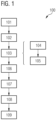
- FIG. 1 a process diagram of a method 100 according to the invention is shown.
- the method 100 comprises transmitting 101 a first plurality of measurement pulses 13 within a first measurement interval 10 at first transmission times and transmitting 101 a second plurality of measurement pulses 13 within a second measurement interval 11 at second transmission times.
- the method 100 comprises receiving 103 reflected measurement pulses by means of a receiving element of a receiving unit assigned to the transmitting element at reception times.
- a short section of the measuring range can be previously assigned a short section of the measuring range, a short section of the receiving element, and a short interval of the corresponding measuring interval.
- a mid section of the measuring range can be assigned a mid interval of the measuring interval and a mid section of the receiving element
- a far section of the measuring range can be assigned a far section of the measuring range and a far interval of the measuring interval 104.
- the short section, the mid section, and the far section can be controlled 105 based on the short interval, the mid interval, and the far interval of the first measuring interval 10.
- the method 100 comprises determining 106 a first set of propagation times and determining 107 a second set of propagation times for each received measurement pulse. Furthermore, the method 100 comprises creating 108 a histogram for the receiving element and entering the first set and/or second set of propagation times into the histogram 15. The method may further comprise determining 109 a distance from the histogram 15.
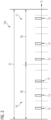
- Figure 2 shows schematically two directly consecutive measuring intervals, a first measuring interval 10 and a second measuring interval 11, which are plotted against time 12.
- the detection interval 10a is also shown, which begins at the same time as the first measuring interval 10, but is twice as long and thus also extends over the second measuring interval 11.
- the detection interval 10a can be assigned to the first measuring interval 10 or to both measuring intervals as a common detection interval 10a.
- the lengths 30 of the measurement intervals and the length 31 of the detection interval 10a are clearly shown. In each measurement interval, three measurement pulses 13 are emitted, the time intervals of which are randomly selected.
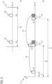
- the histogram 15 is shown, which plots entries 16 over time 12 from the beginning of the first measurement interval 10.
- the hatched positions in the histogram that would be entered without any consideration of the transmission times are shown. In other words, these are the "uncorrected" measured reception times of the two received measurement pulses, namely the first reception time 17a for the first measurement pulse 13a and the second reception time 17b for the second measurement pulse 13b.
- the short arrows on the lower side of the histogram 15 show a shift of these "uncorrected positions" around the first transmission time 14a of the first measurement pulse 13a.
- the longer arrows shown above show the respective shift 19 around the second transmission time of the second measurement pulse 13b.
- the shifts ensure compensation with regard to the different transmission times. In other words, all possible transmission times are taken into account by subtracting them from the reception times.
- the hatched entries are not entered, while the other travel times determined by the compensations are entered.
- Four runtimes are determined, which form the first set of runtimes, and are entered at the respective positions. It is clearly visible how two entries, one based on the reception of the first measurement pulse 13a and one based on the reception of the second measurement pulse 13b, overlap at one position. This marks the correct runtime 20, while the incorrect runtimes 21 are distributed symmetrically around the correct runtime 20 in the histogram 15.
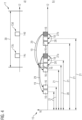
- FIG. 4 a second measurement of a second measurement interval 11 is shown.
- the first transmission time 14c of a first measurement pulse 13c of the second measurement interval 11 and a second transmission time 14d of a second measurement pulse 13d of the second measurement interval 11 can be seen.
- section b) of the Figure 4 shows how the hatched reception times, namely the first reception time 27a for the first measurement pulse 13c and the second reception time 27b for the second measurement pulse 13d, are compensated in the histogram. Compensation is achieved by corresponding shifts, namely initially by a corresponding shift 18 by the first transmission time 14a of the first measurement interval 10, a shift 19 by the second transmission time 14b of the first measurement interval 10, a shift 28 by the first transmission time 14c of the second measurement interval 11, and a shift 29 by the second transmission time 14d of the second measurement interval 11. Compensation is achieved in each case by subtracting the corresponding transmission times from the respective reception time.
- Figure 5 are the histograms 15 of the different measurements of the Figures 3 and 4 shown, where section a) shows the histogram 15 of the first measurement of the first measurement interval 10 of the Figure 3 and section b) shows the histogram 15 of the second Measurement of the second measurement interval 11 of the Figure 4 .
- section c) a superimposed histogram 15 of the two measurements is shown, which clearly shows how an entry of all received measuring pulses is superimposed at the correct position and thus the correct propagation time 20 and thus distance can be read from the histogram in the simplest way by determining the maximum.
Landscapes
- Engineering & Computer Science (AREA)
- Physics & Mathematics (AREA)
- Computer Networks & Wireless Communication (AREA)
- General Physics & Mathematics (AREA)
- Radar, Positioning & Navigation (AREA)
- Remote Sensing (AREA)
- Electromagnetism (AREA)
- Optical Radar Systems And Details Thereof (AREA)
- Measurement Of Optical Distance (AREA)
Claims (13)
- Procédé (100) de mesure optique de distance,dans lequel, à l'intérieur d'un premier intervalle de mesure (10), une première pluralité d'impulsions de mesure (13) est émise (101) au moyen d'un élément d'émission d'une unité d'émission à des premiers instants d'émission,dans lequel, à l'intérieur d'un deuxième intervalle de mesure (11), une deuxième pluralité d'impulsions de mesure (13) est émise (102) au moyen de l'élément d'émission de l'unité d'émission à des deuxièmes instants d'émission,le procédé (100) comprenant la réception (103) d'impulsions de mesure réfléchies au moyen d'un élément de réception d'une unité de réception associé à l'élément d'émission à des instants de réception,caractérisé en ce quele procédé (100) comprend la détermination (106) d'un premier ensemble de temps de transit pour chaque impulsion de mesure reçue,dans lequel le premier ensemble de temps de transit est déterminé en utilisant les premiers instants d'émission, le procédé (100) comprenant la détermination (107) d'un second ensemble de temps de transit pour chaque impulsion de mesure reçue,dans lequel le deuxième ensemble de temps de transit est déterminé en utilisant les deuxièmes instants d'émission,dans lequel le premier ensemble de temps de transit est déterminé en utilisant les premiers instants d'émission de telle sorte que chaque premier instant d'émission est soustrait de l'instant de réception de l'impulsion de mesure reçue respective, dans lequel le second ensemble de temps de transit est déterminé en utilisant les seconds instants d'émission de telle sorte que chaque second instant d'émission est soustrait de l'instant de réception de l'impulsion de mesure reçue respective,le premier intervalle de mesure (10) et le deuxième intervalle de mesure (11) se succédant directement dans le temps,dans lequel le procédé (100) comprend la création (108) d'au moins un histogramme (15) pour l'élément de réception et l'inscription de la première quantité et/ou de la deuxième quantité de temps de transit dans l'histogramme.
- Procédé selon la revendication 1,
caractérisé en ce quele premier intervalle de mesure (10) et/ou le deuxième intervalle de mesure (11) présente une longueur,la longueur étant adaptée à la longueur simple ou double de la plage de mesure. - Procédé (100) selon l'une quelconque des revendications précédentes, caractérisé en ce que
l'histogramme (15) présente la longueur de l'intervalle de mesure. - Procédé (100) selon l'une des revendications 2 ou 3,
caractérisé en ce que
seuls des temps de transit supérieurs à zéro et inférieurs à la longueur de l'intervalle de mesure sont inscrits dans l'histogramme. - Procédé (100) selon l'une quelconque des revendications précédentes, caractérisé en ce que
un nombre égal d'impulsions de mesure (13) est émis dans le premier intervalle de mesure (10) et dans le deuxième intervalle de mesure (11). - Procédé (100) selon l'une quelconque des revendications précédentes, caractérisé en ce que
des impulsions de mesure voisines (13) de la pluralité d'impulsions de mesure (13) émises à l'intérieur du premier intervalle de mesure (10) et/ou des impulsions de mesure voisines (13) de la pluralité d'impulsions de mesure émises à l'intérieur du deuxième intervalle de mesure (11) présentent un écart aléatoire entre elles. - Procédé (100) selon l'une quelconque des revendications précédentes, caractérisé en ce que
la pluralité d'impulsions de mesure (13) émises à l'intérieur du premier intervalle de mesure (10) et/ou la pluralité d'impulsions de mesure (13) émises à l'intérieur du deuxième intervalle de mesure (11) sont codées. - Procédé (100) selon l'une quelconque des revendications précédentes, caractérisé en ce que
au moins deux des impulsions de mesure émises à l'intérieur du premier intervalle de mesure (10) ou du deuxième intervalle de mesure (11) se distinguent par leur forme d'impulsion. - Procédé (100) selon l'une des revendications 1 ou 3 à 8,caractérisé en ce quela plage de mesure est divisée en au moins une section courte, une section moyenne et une section loin,dans lequel des impulsions de mesure réfléchies provenant de la section courte, de la section moyenne et de la section loin sont reçues dans différentes zones d'une zone d'imagerie de l'élément de réception,dans lequel un intervalle court de l'intervalle de mesure et une zone courte de l'élément de réception sont affectés à la section courte, un intervalle moyen de l'intervalle de mesure et une zone moyenne de l'élément de réception sont affectés à la section moyenne, et un intervalle loin de l'intervalle de mesure et une zone loin de l'élément de réception sont affectés à la section loin.
- Procédé (100) selon la revendication 9,
caractérisé en ce que
la plage courte, la plage moyenne et la plage loin de l'élément de réception sont commandées sur la base de l'intervalle court, de l'intervalle moyen et de l'intervalle loin du premier intervalle de mesure. - Dispositif de mesure optique de distance,dans lequel le dispositif présente une unité d'émission comprenant plusieurs éléments d'émission pour émettre des impulsions de mesure et une unité de réception comprenant plusieurs éléments de réception pour recevoir des impulsions de mesure réfléchies,caractérisé en ce quele dispositif est conçu pour mettre en oeuvre un procédé (100) selon l'une des revendications 1 à 10.
- Produit programme d'ordinateur comprenant un support de stockage lisible par ordinateur sur lequel est stocké un programme qui, après avoir été chargé dans la mémoire de l'ordinateur, permet à un ordinateur d'exécuter un procédé (100) selon l'une quelconque des revendications 1 à 10 en coopération avec un dispositif selon la revendication 11.
- Support de stockage lisible par ordinateur sur lequel est stocké un programme qui, après avoir été chargé dans la mémoire de l'ordinateur, permet à un ordinateur d'exécuter un procédé selon l'une quelconque des revendications 1 à 10 en coopération avec un dispositif selon la revendication 11.
Applications Claiming Priority (1)
| Application Number | Priority Date | Filing Date | Title |
|---|---|---|---|
| EP19205601 | 2019-10-28 |
Publications (2)
| Publication Number | Publication Date |
|---|---|
| EP3816656A1 EP3816656A1 (fr) | 2021-05-05 |
| EP3816656B1 true EP3816656B1 (fr) | 2025-06-11 |
Family
ID=68382283
Family Applications (1)
| Application Number | Title | Priority Date | Filing Date |
|---|---|---|---|
| EP20204308.9A Active EP3816656B1 (fr) | 2019-10-28 | 2020-10-28 | Procédé et dispositif de mesure optique de distance |
Country Status (7)
| Country | Link |
|---|---|
| US (1) | US11796649B2 (fr) |
| EP (1) | EP3816656B1 (fr) |
| JP (1) | JP7125968B2 (fr) |
| KR (1) | KR102490795B1 (fr) |
| CN (1) | CN112799034A (fr) |
| CA (1) | CA3097277C (fr) |
| IL (1) | IL278357B2 (fr) |
Families Citing this family (6)
| Publication number | Priority date | Publication date | Assignee | Title |
|---|---|---|---|---|
| US11536811B2 (en) * | 2019-12-06 | 2022-12-27 | National Chiao Tung University | Distance measuring device and method |
| US20220381918A1 (en) * | 2021-05-28 | 2022-12-01 | Continental Automotive Systems, Inc. | Lidar sensor histogram computation |
| DE102021208089A1 (de) | 2021-07-27 | 2023-02-02 | Robert Bosch Gesellschaft mit beschränkter Haftung | Verfahren zum Betreiben einer LiDAR-Einrichtung |
| US20230358865A1 (en) * | 2022-05-06 | 2023-11-09 | Lg Innotek Co., Ltd. | Lidar range enhancement using pulse coding |
| US12541028B2 (en) * | 2022-08-31 | 2026-02-03 | Lg Innotek Co., Ltd. | Systems and methods for clock-skew search to improve depth accuracy in Geiger mode lidar |
| JP2024048232A (ja) * | 2022-09-27 | 2024-04-08 | ソニーセミコンダクタソリューションズ株式会社 | 光検出装置及び測距システム |
Family Cites Families (17)
| Publication number | Priority date | Publication date | Assignee | Title |
|---|---|---|---|---|
| US9417326B2 (en) | 2009-06-22 | 2016-08-16 | Toyota Motor Europe Nv/Sa | Pulsed light optical rangefinder |
| AT511310B1 (de) * | 2011-04-07 | 2013-05-15 | Riegl Laser Measurement Sys | Verfahren zur entfernungsmessung |
| KR101405662B1 (ko) * | 2011-12-12 | 2014-06-10 | 현대자동차주식회사 | 노면의 형상 표시 장치 및 그 방법 |
| IL239919A (en) * | 2015-07-14 | 2016-11-30 | Brightway Vision Ltd | Branded template lighting |
| EP3182159B1 (fr) * | 2015-12-15 | 2018-09-26 | Riegl Laser Measurement Systems GmbH | Dispositif telemetrique |
| EP3232224B1 (fr) * | 2016-04-12 | 2018-06-13 | Sick Ag | Capteur telemetrique optoelectronique et procede de detection et de determination de distances entre des objets |
| US10690756B2 (en) * | 2016-05-10 | 2020-06-23 | Texas Instruments Incorporated | Methods and apparatus for LIDAR operation with pulse position modulation |
| DE102016011299A1 (de) | 2016-09-19 | 2018-03-22 | Blickfeld GmbH | Codierte Laserlicht-Pulssequenzen für LIDAR |
| US10884126B2 (en) * | 2017-03-01 | 2021-01-05 | Ouster, Inc. | Accurate photo detector measurements for LIDAR |
| DE102017208704A1 (de) | 2017-05-23 | 2018-11-29 | Robert Bosch Gmbh | Vorrichtung und Verfahren zur Entfernungsmessung |
| EP3428683B1 (fr) | 2017-07-11 | 2019-08-28 | Sick Ag | Capteur optoélectronique et procédé de mesure de distance |
| JP6911674B2 (ja) | 2017-09-26 | 2021-07-28 | 株式会社リコー | 時間測定装置、測距装置、移動体装置、時間測定方法及び測距方法 |
| DE102018201220A1 (de) * | 2018-01-26 | 2019-08-01 | Osram Gmbh | Abstandsdetektionssystem, Verfahren für ein Abstandsdetektionssystem und Fahrzeug |
| JP6969425B2 (ja) | 2018-02-20 | 2021-11-24 | 株式会社デンソー | 光測距装置 |
| EP3531166B1 (fr) * | 2018-02-21 | 2023-06-07 | MicroVision, Inc. | Procédé et dispositif de mesure de distance optique |
| JP6741039B2 (ja) | 2018-04-04 | 2020-08-19 | 株式会社デンソー | 光測距装置 |
| US10466342B1 (en) * | 2018-09-30 | 2019-11-05 | Hesai Photonics Technology Co., Ltd. | Adaptive coding for lidar systems |
-
2020
- 2020-10-27 CA CA3097277A patent/CA3097277C/fr active Active
- 2020-10-27 JP JP2020179966A patent/JP7125968B2/ja active Active
- 2020-10-27 US US17/081,223 patent/US11796649B2/en active Active
- 2020-10-28 KR KR1020200141140A patent/KR102490795B1/ko active Active
- 2020-10-28 EP EP20204308.9A patent/EP3816656B1/fr active Active
- 2020-10-28 IL IL278357A patent/IL278357B2/en unknown
- 2020-10-28 CN CN202011174837.XA patent/CN112799034A/zh active Pending
Also Published As
| Publication number | Publication date |
|---|---|
| CN112799034A (zh) | 2021-05-14 |
| IL278357B2 (en) | 2024-08-01 |
| EP3816656A1 (fr) | 2021-05-05 |
| JP2021092543A (ja) | 2021-06-17 |
| IL278357B1 (en) | 2024-04-01 |
| CA3097277A1 (fr) | 2021-04-28 |
| JP7125968B2 (ja) | 2022-08-25 |
| US11796649B2 (en) | 2023-10-24 |
| KR102490795B1 (ko) | 2023-01-19 |
| KR20210050478A (ko) | 2021-05-07 |
| IL278357A (en) | 2021-04-29 |
| CA3097277C (fr) | 2025-04-01 |
| US20210124027A1 (en) | 2021-04-29 |
Similar Documents
| Publication | Publication Date | Title |
|---|---|---|
| EP3374793B1 (fr) | Procédé et dispositif de mesure de distance par voie optique | |
| EP3816656A1 (fr) | Procédé et dispositif de mesure optique de distance | |
| EP3779513A1 (fr) | Système lidar aux paramètres de balayage flexibles | |
| DE102018208669B4 (de) | Verfahren und Vorrichtung zur Detektion eines Objekts mittels breitbandiger Laserpulse | |
| EP4193180B1 (fr) | Procédé de détermination de diaphonie optique d'un capteur lidar, et capteur lidar | |
| EP4162289B1 (fr) | Système lidar à commande grossière d'angle | |
| DE102018201220A1 (de) | Abstandsdetektionssystem, Verfahren für ein Abstandsdetektionssystem und Fahrzeug | |
| DE102007028062B4 (de) | Radarvorrichtung | |
| WO2022135956A1 (fr) | Système lidar, véhicule et procédé de fonctionnement | |
| DE102018126522A1 (de) | Laufzeitbasierte Entfernungsmessung unter Verwendung von modulierten Pulsfolgen von Laserpulsen | |
| EP3599485A1 (fr) | Procédé et dispositif de mesure de distance optique | |
| EP3789794B1 (fr) | Procédé et dispositif de mesure de la distance | |
| EP2962127B1 (fr) | Procédé de détermination d'une distance d'un objet par rapport à un véhicule à moteur en utilisant un capteur pmd | |
| EP3531166B1 (fr) | Procédé et dispositif de mesure de distance optique | |
| EP3542181A1 (fr) | Procédé de fonctionnement d'un capteur optoélectronique d'un véhicule à moteur avec commande variable d'une source de lumière, capteur optoélectronique, système d'aide à la conduite et véhicule à moteur | |
| EP3614175B1 (fr) | Procédé et dispositif de mesure de distance optique | |
| EP3531167B1 (fr) | Procédé et dispositif de mesure de distance optique | |
| WO2016169914A1 (fr) | Procédé permettant de faire fonctionner un capteur opto-électronique pour un véhicule comprenant une adaptation de l'émission des signaux d'émission, capteur opto-électronique, système d'assistance au conducteur et véhicule automobile | |
| DE102019100929A1 (de) | Langstreckendetektor für LIDAR | |
| EP2803061B1 (fr) | Procédé de balayage de l'environnement d'un véhicule en mouvement | |
| DE102023134173A1 (de) | Lichtdetektions- und datenerfassungs- und -verarbeitungsvorrichtung, lidar und zugehörige detektionsverfahren | |
| DE102019124141A1 (de) | Lichtlaufzeitkamerasystem | |
| DE102022214040A1 (de) | Verfahren zum Erkennen einer Defokussierung eines LIDAR-Sensors und LIDAR-Sensor | |
| DE102021112942A1 (de) | Verfahren zum Betreiben einer Detektionsvorrichtung, Detektionsvorrichtung und Fahrzeug mit wenigstens einer Detektionsvorrichtung | |
| DE102020215000B4 (de) | Laserbasierte Erfassungseinrichtung, Kraftfahrzeug und Verfahren zum Betreiben einer laserbasierten Erfassungseinrichtung |
Legal Events
| Date | Code | Title | Description |
|---|---|---|---|
| PUAI | Public reference made under article 153(3) epc to a published international application that has entered the european phase |
Free format text: ORIGINAL CODE: 0009012 |
|
| STAA | Information on the status of an ep patent application or granted ep patent |
Free format text: STATUS: THE APPLICATION HAS BEEN PUBLISHED |
|
| AK | Designated contracting states |
Kind code of ref document: A1 Designated state(s): AL AT BE BG CH CY CZ DE DK EE ES FI FR GB GR HR HU IE IS IT LI LT LU LV MC MK MT NL NO PL PT RO RS SE SI SK SM TR |
|
| STAA | Information on the status of an ep patent application or granted ep patent |
Free format text: STATUS: REQUEST FOR EXAMINATION WAS MADE |
|
| 17P | Request for examination filed |
Effective date: 20210920 |
|
| RBV | Designated contracting states (corrected) |
Designated state(s): AL AT BE BG CH CY CZ DE DK EE ES FI FR GB GR HR HU IE IS IT LI LT LU LV MC MK MT NL NO PL PT RO RS SE SI SK SM TR |
|
| RAP1 | Party data changed (applicant data changed or rights of an application transferred) |
Owner name: MICROVISION, INC. |
|
| P01 | Opt-out of the competence of the unified patent court (upc) registered |
Effective date: 20230530 |
|
| GRAP | Despatch of communication of intention to grant a patent |
Free format text: ORIGINAL CODE: EPIDOSNIGR1 |
|
| STAA | Information on the status of an ep patent application or granted ep patent |
Free format text: STATUS: GRANT OF PATENT IS INTENDED |
|
| INTG | Intention to grant announced |
Effective date: 20250304 |
|
| GRAS | Grant fee paid |
Free format text: ORIGINAL CODE: EPIDOSNIGR3 |
|
| GRAA | (expected) grant |
Free format text: ORIGINAL CODE: 0009210 |
|
| STAA | Information on the status of an ep patent application or granted ep patent |
Free format text: STATUS: THE PATENT HAS BEEN GRANTED |
|
| AK | Designated contracting states |
Kind code of ref document: B1 Designated state(s): AL AT BE BG CH CY CZ DE DK EE ES FI FR GB GR HR HU IE IS IT LI LT LU LV MC MK MT NL NO PL PT RO RS SE SI SK SM TR |
|
| REG | Reference to a national code |
Ref country code: GB Ref legal event code: FG4D Free format text: NOT ENGLISH |
|
| REG | Reference to a national code |
Ref country code: CH Ref legal event code: EP |
|
| REG | Reference to a national code |
Ref country code: IE Ref legal event code: FG4D Free format text: LANGUAGE OF EP DOCUMENT: GERMAN |
|
| REG | Reference to a national code |
Ref country code: DE Ref legal event code: R096 Ref document number: 502020011193 Country of ref document: DE |
|
| PG25 | Lapsed in a contracting state [announced via postgrant information from national office to epo] |
Ref country code: FI Free format text: LAPSE BECAUSE OF FAILURE TO SUBMIT A TRANSLATION OF THE DESCRIPTION OR TO PAY THE FEE WITHIN THE PRESCRIBED TIME-LIMIT Effective date: 20250611 Ref country code: ES Free format text: LAPSE BECAUSE OF FAILURE TO SUBMIT A TRANSLATION OF THE DESCRIPTION OR TO PAY THE FEE WITHIN THE PRESCRIBED TIME-LIMIT Effective date: 20250611 |
|
| REG | Reference to a national code |
Ref country code: LT Ref legal event code: MG9D |
|
| PG25 | Lapsed in a contracting state [announced via postgrant information from national office to epo] |
Ref country code: GR Free format text: LAPSE BECAUSE OF FAILURE TO SUBMIT A TRANSLATION OF THE DESCRIPTION OR TO PAY THE FEE WITHIN THE PRESCRIBED TIME-LIMIT Effective date: 20250912 Ref country code: NO Free format text: LAPSE BECAUSE OF FAILURE TO SUBMIT A TRANSLATION OF THE DESCRIPTION OR TO PAY THE FEE WITHIN THE PRESCRIBED TIME-LIMIT Effective date: 20250911 |
|
| REG | Reference to a national code |
Ref country code: NL Ref legal event code: MP Effective date: 20250611 |
|
| PG25 | Lapsed in a contracting state [announced via postgrant information from national office to epo] |
Ref country code: BG Free format text: LAPSE BECAUSE OF FAILURE TO SUBMIT A TRANSLATION OF THE DESCRIPTION OR TO PAY THE FEE WITHIN THE PRESCRIBED TIME-LIMIT Effective date: 20250611 |
|
| PGFP | Annual fee paid to national office [announced via postgrant information from national office to epo] |
Ref country code: GB Payment date: 20250904 Year of fee payment: 6 |
|
| PG25 | Lapsed in a contracting state [announced via postgrant information from national office to epo] |
Ref country code: HR Free format text: LAPSE BECAUSE OF FAILURE TO SUBMIT A TRANSLATION OF THE DESCRIPTION OR TO PAY THE FEE WITHIN THE PRESCRIBED TIME-LIMIT Effective date: 20250611 |
|
| PGFP | Annual fee paid to national office [announced via postgrant information from national office to epo] |
Ref country code: FR Payment date: 20250908 Year of fee payment: 6 |
|
| PG25 | Lapsed in a contracting state [announced via postgrant information from national office to epo] |
Ref country code: RS Free format text: LAPSE BECAUSE OF FAILURE TO SUBMIT A TRANSLATION OF THE DESCRIPTION OR TO PAY THE FEE WITHIN THE PRESCRIBED TIME-LIMIT Effective date: 20250911 |
|
| PG25 | Lapsed in a contracting state [announced via postgrant information from national office to epo] |
Ref country code: LV Free format text: LAPSE BECAUSE OF FAILURE TO SUBMIT A TRANSLATION OF THE DESCRIPTION OR TO PAY THE FEE WITHIN THE PRESCRIBED TIME-LIMIT Effective date: 20250611 |
|
| PG25 | Lapsed in a contracting state [announced via postgrant information from national office to epo] |
Ref country code: NL Free format text: LAPSE BECAUSE OF FAILURE TO SUBMIT A TRANSLATION OF THE DESCRIPTION OR TO PAY THE FEE WITHIN THE PRESCRIBED TIME-LIMIT Effective date: 20250611 |
|
| PG25 | Lapsed in a contracting state [announced via postgrant information from national office to epo] |
Ref country code: PT Free format text: LAPSE BECAUSE OF FAILURE TO SUBMIT A TRANSLATION OF THE DESCRIPTION OR TO PAY THE FEE WITHIN THE PRESCRIBED TIME-LIMIT Effective date: 20251013 |
|
| PG25 | Lapsed in a contracting state [announced via postgrant information from national office to epo] |
Ref country code: IS Free format text: LAPSE BECAUSE OF FAILURE TO SUBMIT A TRANSLATION OF THE DESCRIPTION OR TO PAY THE FEE WITHIN THE PRESCRIBED TIME-LIMIT Effective date: 20251011 |
|
| PGFP | Annual fee paid to national office [announced via postgrant information from national office to epo] |
Ref country code: DE Payment date: 20250902 Year of fee payment: 6 |
|
| PG25 | Lapsed in a contracting state [announced via postgrant information from national office to epo] |
Ref country code: SM Free format text: LAPSE BECAUSE OF FAILURE TO SUBMIT A TRANSLATION OF THE DESCRIPTION OR TO PAY THE FEE WITHIN THE PRESCRIBED TIME-LIMIT Effective date: 20250611 |
|
| PG25 | Lapsed in a contracting state [announced via postgrant information from national office to epo] |
Ref country code: CZ Free format text: LAPSE BECAUSE OF FAILURE TO SUBMIT A TRANSLATION OF THE DESCRIPTION OR TO PAY THE FEE WITHIN THE PRESCRIBED TIME-LIMIT Effective date: 20250611 |
|
| PG25 | Lapsed in a contracting state [announced via postgrant information from national office to epo] |
Ref country code: PL Free format text: LAPSE BECAUSE OF FAILURE TO SUBMIT A TRANSLATION OF THE DESCRIPTION OR TO PAY THE FEE WITHIN THE PRESCRIBED TIME-LIMIT Effective date: 20250611 |
|
| PG25 | Lapsed in a contracting state [announced via postgrant information from national office to epo] |
Ref country code: EE Free format text: LAPSE BECAUSE OF FAILURE TO SUBMIT A TRANSLATION OF THE DESCRIPTION OR TO PAY THE FEE WITHIN THE PRESCRIBED TIME-LIMIT Effective date: 20250611 |
|
| PG25 | Lapsed in a contracting state [announced via postgrant information from national office to epo] |
Ref country code: SK Free format text: LAPSE BECAUSE OF FAILURE TO SUBMIT A TRANSLATION OF THE DESCRIPTION OR TO PAY THE FEE WITHIN THE PRESCRIBED TIME-LIMIT Effective date: 20250611 Ref country code: RO Free format text: LAPSE BECAUSE OF FAILURE TO SUBMIT A TRANSLATION OF THE DESCRIPTION OR TO PAY THE FEE WITHIN THE PRESCRIBED TIME-LIMIT Effective date: 20250611 |
|
| REG | Reference to a national code |
Ref country code: DE Ref legal event code: R097 Ref document number: 502020011193 Country of ref document: DE |
|
| PG25 | Lapsed in a contracting state [announced via postgrant information from national office to epo] |
Ref country code: DK Free format text: LAPSE BECAUSE OF FAILURE TO SUBMIT A TRANSLATION OF THE DESCRIPTION OR TO PAY THE FEE WITHIN THE PRESCRIBED TIME-LIMIT Effective date: 20250611 |
|
| PG25 | Lapsed in a contracting state [announced via postgrant information from national office to epo] |
Ref country code: IT Free format text: LAPSE BECAUSE OF FAILURE TO SUBMIT A TRANSLATION OF THE DESCRIPTION OR TO PAY THE FEE WITHIN THE PRESCRIBED TIME-LIMIT Effective date: 20250611 |
|
| PLBE | No opposition filed within time limit |
Free format text: ORIGINAL CODE: 0009261 |
|
| STAA | Information on the status of an ep patent application or granted ep patent |
Free format text: STATUS: NO OPPOSITION FILED WITHIN TIME LIMIT |
|
| REG | Reference to a national code |
Ref country code: CH Ref legal event code: L10 Free format text: ST27 STATUS EVENT CODE: U-0-0-L10-L00 (AS PROVIDED BY THE NATIONAL OFFICE) Effective date: 20260423 |