EP3816745B1 - Vorrichtung zum automatischen betrieb eines bearbeitungszentrums mittels cad-daten - Google Patents
Vorrichtung zum automatischen betrieb eines bearbeitungszentrums mittels cad-daten Download PDFInfo
- Publication number
- EP3816745B1 EP3816745B1 EP19918498.7A EP19918498A EP3816745B1 EP 3816745 B1 EP3816745 B1 EP 3816745B1 EP 19918498 A EP19918498 A EP 19918498A EP 3816745 B1 EP3816745 B1 EP 3816745B1
- Authority
- EP
- European Patent Office
- Prior art keywords
- machining
- tool
- automatic
- manufacturing process
- unit
- Prior art date
- Legal status (The legal status is an assumption and is not a legal conclusion. Google has not performed a legal analysis and makes no representation as to the accuracy of the status listed.)
- Active
Links
Images


Classifications
-
- G—PHYSICS
- G05—CONTROLLING; REGULATING
- G05B—CONTROL OR REGULATING SYSTEMS IN GENERAL; FUNCTIONAL ELEMENTS OF SUCH SYSTEMS; MONITORING OR TESTING ARRANGEMENTS FOR SUCH SYSTEMS OR ELEMENTS
- G05B19/00—Program-control systems
- G05B19/02—Program-control systems electric
- G05B19/18—Numerical control [NC], i.e. automatically operating machines, in particular machine tools, e.g. in a manufacturing environment, so as to execute positioning, movement or co-ordinated operations by means of program data in numerical form
- G05B19/4097—Numerical control [NC], i.e. automatically operating machines, in particular machine tools, e.g. in a manufacturing environment, so as to execute positioning, movement or co-ordinated operations by means of program data in numerical form characterised by using design data to control NC machines, e.g. CAD/CAM
-
- G—PHYSICS
- G05—CONTROLLING; REGULATING
- G05B—CONTROL OR REGULATING SYSTEMS IN GENERAL; FUNCTIONAL ELEMENTS OF SUCH SYSTEMS; MONITORING OR TESTING ARRANGEMENTS FOR SUCH SYSTEMS OR ELEMENTS
- G05B19/00—Program-control systems
- G05B19/02—Program-control systems electric
- G05B19/18—Numerical control [NC], i.e. automatically operating machines, in particular machine tools, e.g. in a manufacturing environment, so as to execute positioning, movement or co-ordinated operations by means of program data in numerical form
- G05B19/406—Numerical control [NC], i.e. automatically operating machines, in particular machine tools, e.g. in a manufacturing environment, so as to execute positioning, movement or co-ordinated operations by means of program data in numerical form characterised by monitoring or safety
- G05B19/4068—Verifying part program on screen, by drawing or other means
-
- G—PHYSICS
- G05—CONTROLLING; REGULATING
- G05B—CONTROL OR REGULATING SYSTEMS IN GENERAL; FUNCTIONAL ELEMENTS OF SUCH SYSTEMS; MONITORING OR TESTING ARRANGEMENTS FOR SUCH SYSTEMS OR ELEMENTS
- G05B2219/00—Program-control systems
- G05B2219/30—Nc systems
- G05B2219/35—Nc in input of data, input till input file format
- G05B2219/35159—With nominal blank and model in memory define tool path and machine workpiece
-
- G—PHYSICS
- G05—CONTROLLING; REGULATING
- G05B—CONTROL OR REGULATING SYSTEMS IN GENERAL; FUNCTIONAL ELEMENTS OF SUCH SYSTEMS; MONITORING OR TESTING ARRANGEMENTS FOR SUCH SYSTEMS OR ELEMENTS
- G05B2219/00—Program-control systems
- G05B2219/30—Nc systems
- G05B2219/35—Nc in input of data, input till input file format
- G05B2219/35165—Automatic cutter selection
-
- G—PHYSICS
- G05—CONTROLLING; REGULATING
- G05B—CONTROL OR REGULATING SYSTEMS IN GENERAL; FUNCTIONAL ELEMENTS OF SUCH SYSTEMS; MONITORING OR TESTING ARRANGEMENTS FOR SUCH SYSTEMS OR ELEMENTS
- G05B2219/00—Program-control systems
- G05B2219/30—Nc systems
- G05B2219/35—Nc in input of data, input till input file format
- G05B2219/35167—Automatic toolpath generation and tool selection
-
- G—PHYSICS
- G05—CONTROLLING; REGULATING
- G05B—CONTROL OR REGULATING SYSTEMS IN GENERAL; FUNCTIONAL ELEMENTS OF SUCH SYSTEMS; MONITORING OR TESTING ARRANGEMENTS FOR SUCH SYSTEMS OR ELEMENTS
- G05B2219/00—Program-control systems
- G05B2219/30—Nc systems
- G05B2219/35—Nc in input of data, input till input file format
- G05B2219/35287—Verify, check program by drawing, display part, testpiece
-
- G—PHYSICS
- G05—CONTROLLING; REGULATING
- G05B—CONTROL OR REGULATING SYSTEMS IN GENERAL; FUNCTIONAL ELEMENTS OF SUCH SYSTEMS; MONITORING OR TESTING ARRANGEMENTS FOR SUCH SYSTEMS OR ELEMENTS
- G05B2219/00—Program-control systems
- G05B2219/30—Nc systems
- G05B2219/35—Nc in input of data, input till input file format
- G05B2219/35313—Display, validate tool path for boundary, surface interference
-
- Y—GENERAL TAGGING OF NEW TECHNOLOGICAL DEVELOPMENTS; GENERAL TAGGING OF CROSS-SECTIONAL TECHNOLOGIES SPANNING OVER SEVERAL SECTIONS OF THE IPC; TECHNICAL SUBJECTS COVERED BY FORMER USPC CROSS-REFERENCE ART COLLECTIONS [XRACs] AND DIGESTS
- Y02—TECHNOLOGIES OR APPLICATIONS FOR MITIGATION OR ADAPTATION AGAINST CLIMATE CHANGE
- Y02P—CLIMATE CHANGE MITIGATION TECHNOLOGIES IN THE PRODUCTION OR PROCESSING OF GOODS
- Y02P90/00—Enabling technologies with a potential contribution to greenhouse gas [GHG] emissions mitigation
- Y02P90/02—Total factory control, e.g. smart factories, flexible manufacturing systems [FMS] or integrated manufacturing systems [IMS]
Definitions
- the present invention relates to an automatic operation device of a machining center equipped with a CNC device for machine tools in which time and trouble for a skilled hand to create a machining program using code for an NC language are saved and only by acquiring three-dimensional CAD design data of a machined product, a machining program is automatically created based on the data.
- NC Numerical Control
- NC machining program is created based on machining conditions, including a tool to be used and numeric data (NC data) such as a movement based on coordinate positions in X, Y, Z, and the like and a speed of the tool during machining with the tool and numerical control information on a manufacturing process.
- NC data numeric data
- CNC devices computer numerical control devices
- CNC devices have been used which is further automated by automatically calculating part of numerical control information, for example, correction of a tool diameter, interpolating operation, speed control, and the like with a built-in computer.
- an NC machining program for obtaining a machined product in an intended shape by cutting a material to be machined via automatic operation of a machine tool, especially, a machining center, a machining condition and a manufacturing process for the program must be set beforehand.
- Each manufacturing process is determined based on a machining method for cutting each feature to be formed in a machined product.
- Features cite here refer to step heights of projections and depressions, surface shapes of curves, holes, pockets, slots, and the like in machined products.
- a tool suitable for forming these features is appropriately selected from, for example, various milling cutters suitable for facing, various drills suitable for drilling, various end mills suitable for grooving and shoulder grinding, and the like; a machining condition including a cutting condition is established; and a tool trajectory is determined based on the machining condition. Further, a manufacturing process including the above tool selection, tool change, and execution of a tool trajectory is established and an NC machining program corresponding to the manufacturing process is created.
- an NC machining program itself is created by an engineer using an NC language, such as G code and M code, based on a CAD (Computer Aided Design) design drawing of a machined product.
- CAD Computer Aided Design
- machining has been performed with a sophisticated machine tool, such as simultaneous up to five-axis (X, Y, Z, A, C) control. For this reason, complicated control in which these multiple axes will not interfere with one another is required. Therefore, an NC machining program is also created using CAM (Computer Aided Manufacturing) system based on a three-dimensional CAD diagram.
- CAM Computer Aided Manufacturing
- Patent Literature 1 discloses an automatic program creation device in which a cutting condition is determined according to shape and attribute data from a data input unit, a tool path is determined in accordance with the cutting condition, and an NC machining program is created based on the tool path.
- Patent Literature 2 a different automatic machining information generation device has also been developed (Refer to Patent Literature 2).
- a region to be machined is extracted from CAD design data and a machining shape is determined; an applicable tool is selected from a tool database; a cutting speed, a feed speed, and the like are automatically calculated by reading a recommended machining speed and a recommended feed speed for this operation from a machining condition database; and then a tool trajectory is generated and a machining program is created.
- a CAM system has also been considered (Refer to Patent Literature 3, for example).
- feature data for a machined product is extracted from CAD data and a manufacturing process and a machining area for each manufacturing process are established; material data and a machining model of each manufacturing process are generated; a tool path data is generated based on a tool database and a machining condition database and an NC machining program is then created.
- Patent Literature 4 discloses that an intelligent numerical control machining programming system and method for aircraft structural parts, the system employs an existing CAD/CAM system as a platform, being set up upon a three-dimensional model, and gives a comparatively systematical and accurate reflection of and also support to the professional procedures of the numerical control machining programming for aircraft structural parts.
- Patent Literature 5 discloses that methods and apparatus for training a set of regression machine learning models with a training set to produce a set of predictive values for a pending manufacturing request as methods and apparatus for machine learning predictions and multi-objective optimization of manufacturing processes, the training set including data extracted from a set of manufacturing transactions submitted by a set of entities of a supply chain, and a multi-objective optimization model is implemented to receive an input including the set of predictive values and a set of features of a physical object, and generate an output with a set of attributes associated with a manufacture of the physical object in response to receiving the input.
- Patent Literature 6 discloses that systems and method relating to machining parts include a CNC system, and a computer including a processor and a computer-readable medium, as method and system for processing machine data before completion of machining, wherein the computer-readable medium encodes instructions including receiving, at the computer program, output data from a CNC machine that receives instructions of a Numerical Control (NC) program at a computer of the CNC machine, the instructions causing the CNC machine to i) manufacture a part, and ii) output the output data, parsing, by the computer program, the output data before completion of the manufacturing of the part by the CNC machine in accordance with the instructions of the NC program, selecting, by the computer program and based on one or more predetermined parameters, a set of data from the parsed output data; and providing, by the computer program to a remote system, the set of data for processing to facilitate machining using the CNC machine.
- NC Numerical Control
- an object of the present invention to provide an automatic operation device of a machining center that enables automatic, immediate execution of a manufacturing process on the spot and simple manufacture of an intended machined product just by acquiring three-dimensional CAD design data of the machined product.
- the present invention is an automatic operation device of a machining center comprising a CNC device and a machine tool, wherein the CNC device is configured to be connected to the machine tool and to perform numerical control.
- the CNC device includes:
- the control unit is configured to perform drive control on the machining unit of the machine tool in accordance with a predetermined machining program and to causes the material to be machined to be cut while changing and attaching tools to the rotary main spindle in correspondence with each manufacturing process.
- the automatic machining command generation unit has: a feature extraction function of extracting features to be subjected to a cutting operation from three-dimensional CAD design data of the machined product on the basis of the shape of the material to be machined, wherein the feature comprises step heights of projections and depressions, surface shapes of curves, holes, pockets and slots; an automatic manufacturing process setting function of automatically determining machining conditions required for cutting with respect to each feature and automatically setting a manufacturing process including a tool trajectory based on the machining conditions, by applying each extracted feature to the learned model; an all manufacturing process setting function of determining a procedure for performing manufacturing processes for all the features and setting a series of all the manufacturing processes required up to the finish of the machined product; and a machining command generation function of generating a machining command for causing the machine tool to perform all the set manufacturing processes based on the learned model.
- the automatic manufacturing process setting function further includes a function of: generating a 3D model of the machined product based on the three-dimensional CAD design data and causing the displaying unit to display the 3D model; and selecting one or more different mounting directions in which the machined product can be mounted on the machining unit and the 3D model in each selected mounting direction to be displayed in a selectable manner and the manufacturing process for cutting each feature is automatically set based on the selected and determined mounting direction.
- the machining conditions cited in relation to the present invention are the same as machining conditions set on an ordinary machine tool.
- the machining conditions are conditions required for determining a manufacturing process and mainly includes a type and a shape of a tool, a diameter and a material of a tool, and cutting conditions including main spindle rotational speed, cutting feed, cutting width, a depth of cut (in Z direction) of a cutter, and the like as well as the properties of a material to be machined, a method for clamping with a machining unit jig, a clamp position, a mounting direction, and the like.
- a tool trajectory, a so-called tool path is determined for obtaining each intended cut feature based on these machining conditions.
- the CNC device can be caused to acquire three-dimensional CAD design data of an intended machined product stored in, for example, USB via a USB port.
- the CNC device can be caused to acquire three-dimensional CAD design data of the intended machined product from another computer on a computer network via network communication.
- features to be formed by cutting are extracted on the basis of a shape of a material to be machined based on three-dimensional CAD design data of an intended machined product acquired as mentioned above; machining conditions for each feature are automatically determined by applying the feature to the learned model stored in the storage unit; a tool to be used and a tool trajectory are determined based on the machining conditions; and a manufacturing process including specifying and changing the tool and up to execution of the tool trajectory is automatically set.
- a procedure for performing the manufacturing processes for all the features is determined and a series of all the manufacturing processes is set; and a machining command for causing the machine tool to perform all the set manufacturing processes is efficiently and automatically set based on the learned model. Therefore, an operator's necessity for creating an NC program in advance is obviated and the machined product is automatically and immediately manufactured on the spot only by inputting three-dimensional CAD design data to the CNC device.
- the learned model is obtained by learning machining conditions including a tool used and cutting conditions and machining data including a tool trajectory and an execution program for the trajectory for each of various features with respect to an enormous amount of past cutting operation data accumulated by the present inventors et al. That is, the learned model is obtained by learning all the pieces of data required for cutting each feature in correspondence with one another. Therefore, machining conditions required for cutting features for the manufacture of a new machined product and a manufacturing process including a tool trajectory based on the machining conditions are automatically determined and set in a short time based on the learned model. Further, a machining command for causing the machine tool to perform the manufacturing process is also immediately and automatically generated.
- the machining command for causing the machine tool to perform the set manufacturing process may, of course, be an NC program as before.
- the present invention is not limited to a program using such an NC language as G code and any other machining program or any command signal that enables direct drive control on the machine tool may be utilized as long as the set manufacturing process can be performed.
- Execution of a manufacturing process with a machine tool is substantially achieved by performing a tool trajectory with a specified tool.
- This execution of a tool trajectory is implemented by relative linear movement or rotational movement between the tool side and a table or the like on the work side caused by motor drive in each axis. That is, a tool trajectory is performed by drive control on a motor in each axis.
- each motor is driven by a pulse train signal obtained by read NC data being converted at an information processing circuit.
- the pulse train signal instructs actual tool movement by a motor rotation angle corresponding to a number of pulses of the signal, that is, position control and further instructs an actual tool moving speed by rotational speed control on a motor corresponding to a pulse frequency. Therefore, execution of a tool trajectory can be achieved by using a corresponding pulse train signal to directly instruct each motor without intervention of an NC program.
- the machining command for performing the set manufacturing process may include such a command signal that directly controls driving of each motor.
- execution of a series of manufacturing processes can be instructed by what is configured by combining a pulse train signal controlling driving of a motor in each axis corresponding to a tool trajectory with a command signal for tool specification and tool change.
- a pulse train signal itself can be simply generated based on a pulse train signal which has been used in correspondence with various tool trajectories included in machining data learned when the learned model is generated in advance.
- the machining conditions and the tool trajectory for setting the manufacturing process are determined based on a cutting direction of each feature and these cutting directions are determined according to an orientation of the machined product at the time of final completion of cutting. Therefore, the orientation of the machined product, that is, a direction of mounting to a machining unit is determined before the machining conditions and the tool trajectory are determined by the automatic manufacturing process setting function of the automatic machining command generation unit.
- the automatic manufacturing process setting function is further provided with a function of first generating a 3D model of the machined product based on the three-dimensional CAD design data to cause the displaying unit of the CNC device to display the 3D model and selecting one or more different mounting direction in which the machined product is mounted on the machining unit and displaying the 3D model in each selected mounting direction in a selectable manner.
- a mounting direction of the relevant machined product only has to be selected based on the three-dimensional CAD design data. For example, by setting a center axis of a machined product from an external shape of the product, a mounting direction in which an orientation of the center axis is changed can be selected. Specifically, first, a mounting direction in which the center axis is perpendicular and a mounting direction in which the center axis is horizontal can be selected. Aside from the foregoing, a mounting direction in which the center axis is tilted is also selectable depending on an external shape of a machined product.
- a possible placement direction can also be respectively determined. Therefore, when a possible mounting direction of a machined product is only selected based on the three-dimensional CAD design data as mentioned above, multiple mounting directions can be displayed as a 3D model in a very short time. As mentioned above, the most suitable one can be selected from among these automatically displayed mounting directions.
- a machined product often includes at least one face where a cut feature is usually not formed, taking such a face having no feature, that is, a face that does not require cutting as a mounting face is practical. Therefore, an operator can instantaneously select, as the most suitable mounting direction, a mounting direction in which a face of the machined product requiring no cutting provides a mounting face by checking a 3D model in one or more proposed mounting directions on a display.
- the CNC device by causing the CNC device to acquire three-dimensional CAD design data of a machined product, first, one or more possible mounting directions for the product are automatically selected and displayed.
- a machining command that enables execution of all the manufacturing processes up to obtaining the machined product from a material to be machined based on the mounting direction is automatically generated in a short time based on the learned model. Therefore, an operator can cause precision machining to be performed on the material to be machined fixed on the machining unit of the machine tool in a state corresponding to the mounting direction in accordance with the automatically generated machining command just by triggering a cycle start.
- the automatic machining command generation unit is preferably provided with a simulation function for automatically verifying whether the tool trajectory of the set manufacturing process enables smooth machining without interference or not and an interference detection function.
- the simulation function causes the displaying unit to display a tool trajectory of a specified tool in a set manufacturing process as 3D computer graphic moving images, for example, animation moving images.
- the interference detection function stops moving images and causes an interference alert to be displayed when interference occurs between a tool and a non-cutting area of a material to be machined or a peripheral member of the machining unit while the moving images are being displayed.
- An operator can check the presence or absence of interference with respect to a tool trajectory of a specific tool while checking moving images and, when an interference alert is displayed, can simply understand that a machining command generated based on the tool trajectory must be modified.
- the automatic machining command generation unit with a machining command improvement function of, at the time of occurrence of an interference alert, altering the tool with interference to another tool and causing a machining command to be automatically generated again, the automatically generated machining command can be made completely safe.
- this machining command improvement function machining conditions and a tool trajectory based on the machining conditions are newly determined in accordance with the altered tool and an improved manufacturing process is automatically set. Further, an improved machining command corresponding to the thus improved manufacturing process is automatically generated and a simulation process is repeated until interference is eliminated.
- a machining command for a manufacturing process in which a tool trajectory is performed without interference are automatically generated without need for time-consuming verification or the like by a skilled hand; therefore, an operator can easily perform perfect product machining in a short time with peace of mind.
- the displaying unit according to the present invention may be a liquid crystal display or the like conventionally provided in a CNC device. Especially adopting a touch panel type is desirable because a work operation mode can be selected or performed on a display in a shorter time and easily. In this case, when items of various work operation modes are displayed as icons in a menu screen in a selectable and executable manner, workability is further enhanced.
- an item of "CAD data-based automatic operation for machining center” mode from input of the above-mentioned three-dimensional CAD design data to automatic generation and execution of a machining command is displayed as an icon in a menu screen.
- an operator can trigger the "CAD data-based automatic operation for machining center” mode just by touching the icon.
- the operator only has to perform touch operation only when a mounting direction is selected and determined immediately after three-dimensional CAD design data is read and when a complete machining command generated immediately after is started.
- the operator can easily perform manufacture of an intended machined product in a short time as if the operator operated a smartphone.
- the following effect is brought about:
- three-dimensional CAD design data of an intended machined product to be acquired, possible mounting directions are immediately proposed through a 3D model display in a selectable manner and the most suitable mounting direction can be selected and determined.
- extracted features are applied to a learned model and a machining command causing a machine tool to perform all the manufacturing processes required for obtaining the machined product in a short time is automatically generated.
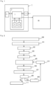
- FIG. 1 illustrates a general configuration of a principal part of an automatic operation device of a machining center in an embodiment of the present invention in the form of block diagram.
- the CNC device in the present embodiment has a basic configuration common to those of conventional CNC devices. A more specific description will be given.
- the CNC device 1 is installed on, for example, an outer wall surface of a guard encircling a machine tool body and a front face of the body of the CNC device is a control panel as shown in FIG. 5 .
- the control panel is provided with a touch panel-type liquid crystal display 11 as a displaying unit.
- the touch panel-type liquid crystal display 11 displays a menu screen in which items of various work operation modes for a machine tool provided in the CNC device 1 in advance are respectively shown as an icon 10.
- a USB port 12 is disposed in the vicinity of the display so that varied data can be inputted and outputted, and a keyboard 15 including a mouse pad 13 and a mouse button 14 is disposed below the display. Further, an operation panel 16 provided with switches and buttons related to various operations of a machine tool is provided in an area below the keyboard 15.
- the CNC device 1 is provided with a "CAD data-based automatic operation" mode as one of work operation modes and is so configured that an icon 10A of that item is also displayed in the menu screen. Therefore, the CAD data-based automatic operation mode can be selected and performed by touching the icon 10A.
- the CNC device 1 Under the control of a control unit 3, the CNC device 1 performs drive control on a machining unit of the machine tool 20 in accordance with a predetermined machining command and causes cutting operation to be performed on a material to be machined while sequentially changing and attaching a tool to a rotary main spindle in correspondence with each manufacturing process.
- a control unit 3 the CNC device 1 performs drive control on a machining unit of the machine tool 20 in accordance with a predetermined machining command and causes cutting operation to be performed on a material to be machined while sequentially changing and attaching a tool to a rotary main spindle in correspondence with each manufacturing process.
- Detailed illustration of the machine tool 20 will be omitted here.
- the control unit 3 of the CNC device 1 is provided with a storage unit 4, in which identification information corresponding to a large number of tools housed in a magazine or the like of the machine tool 20 and tool information 5 such as a type, a shape, a material, and the like of each tool, associated with the identification information are stored. Each tool is managed according to the identification information.
- the machine tool 20 is provided with an automatic tool changer (not shown), and a tool to be used is appropriately specified and changed and attached between the rotary main spindle of the machining unit and the magazine by the changer, with predetermined timing during automatic operation according to a machining program.
- the storage unit 4 is further provided with a learned model 6 generated based on enormous amount of past cutting operation data in advance.
- the learned model 6 was generated by learning machining data as machining conditions including a tool used and cutting conditions and a manufacturing process including a tool trajectory and a machining program with which the manufacturing process was performed, for each feature such as projections and depressions, distortions, holes, pockets, and slots, in faces subjected to various cutting operations, in correspondence with one another.
- the control unit 3 is provided with an automatic machining command generation unit 7 having: an automatic manufacturing process setting function of automatically setting a manufacturing process for forming features of a newly manufactured machined product by applying the features to the learned model 6; and a machining command generation function of automatically generating a machining command for causing the machine tool to perform the manufacturing process.
- the automatic machining command generation unit 7 has a feature extraction function of extracting each feature of a machined product based on acquired three-dimensional CAD design data of the machined product. That is, a feature of a machined product applied to the learned model 6 when a manufacturing process is set and a machining command is generated, is obtained from three-dimensional CAD design data of the machined product by the feature extraction function.
- the automatic manufacturing process setting function of the automatic machining command generation unit 7 further includes a function of: after each feature of the machined product is selected based on three-dimensional CAD design data of the machined product by the feature extraction function, forming a 3D model of the machined product and causing the liquid crystal display 11 to display the 3D model; and selecting one or more possible different mounting directions of the machined product and causing a 3D model in each selected mounting direction to be displayed on the display 11 in a selectable manner. An operator can select and determine the most suitable mounting direction from among those proposed and displayed. Therefore, automatic setting of a manufacturing process is forwarded based on the thus determined mounting direction.
- the automatic machining command generation unit 7 is provided with: a simulation function of causing a tool trajectory of an automatically generated manufacturing process to be displayed on the display 11 as 3D computer graphics, for example, animation moving images; and an interference detection function of, when interference occurs between a tool and a non-cutting area of a material to be machined or a peripheral member of the machining unit while moving images are being displayed, stopping the moving images and causing an interference alert to be displayed.
- the automatic machining command generation unit is also provided with a machining command improvement function of, at the time of an interference alert, altering the tool which caused the interference to a different tool and generating a machining command again.
- FIG. 2 is a flowchart illustrating a machining command generation process
- FIGS. 3(a) and 3(b) and FIGS. 4(a) and 4(b) are schematic diagrams illustrating an example of a screen shown on the display 11 at each step of an automatic manufacturing process setting process.
- the icon 10A corresponding to the "CAD data-based automatic operation" mode is selected in a menu screen displayed on the touch panel-type liquid crystal display 11 of the control panel by touching the icon.
- the CAD data-based automatic operation mode is started (100).
- three-dimensional CAD design data of the target machined product stored in USB is read (101) via a data acquisition unit 2, such as the USB port 12.
- a process of automatic machining command generation is substantially started.
- CAD data may be read from another computer via a computer network using wireless or wired communication, for example, Ethernet (registered trademark) communication.
- the automatic machining command generation unit 7 forms a 3D model of the machined product based on the three-dimensional CAD design data and causes the 3D model to be displayed on the display 11 (102) as illustrated in FIG. 3(a) , and extracts all the features (103). Further, the automatic machining command generation unit selects one or more possible mounting directions of the machined product and displays the 3D model on the display 11 in each selected mounting direction in a selectable and determinable manner.
- the external shape of the machined product is a pentagonal pyramidal prism (a shape obtained by mating a pentagonal pyramid with the upper face of a pentagonal prism) will be taken as an example.
- a mounting direction in which the center axis of the pentagonal pyramidal prism is perpendicular and a mounting direction in which the center axis is horizontal are selected.
- the horizontal mounting direction one of the side faces of the pentagonal prism portion will be selected as a mounting face.
- the mounting direction is determined (104).
- the bottom face of the pentagonal prism portion does not have a feature and does not require cutting. Therefore, a direction in which the bottom face provides a mounting face, that is, the mounting direction in which the center axis is perpendicular can be immediately determined to be practical and most suitable.
- the operator selects an automatic machining command generation start button P on the display 11 by touching the button, after selecting and determining this most suitable mounting direction of the machined product. Then, in the automatic machining command generation unit 7, based on the selected and determined mounting direction, substantial manufacturing process setting (105) is started. Specifically, by applying each feature extracted in advance to the learned model 6, a tool suitable for machining a respective feature is selected from tools registered in the tool information 5 in the storage unit 4 and various cutting conditions and machining conditions are determined. A tool trajectory is also determined based on the machining conditions. Then, a manufacturing process including specifying the tool required for cutting with respect to each feature, mounting the tool, and up to the tool trajectory is set.
- the automatic machining command generation unit 7 identifies the tool that causes the occurrence of interference and selects the second-best tool based on the learned model 6 to perform tool alteration (110). And the automatic machining command generation unit 7 newly determines machining conditions and a machining trajectory with the altered tool and re-sets the manufacturing processes (105). Then, a machining command is generated again (106) in correspondence with the improved manufacturing processes. The above process from the tool alteration to the machining command modification is repeated until the occurrence of interference is eliminated in a simulation; therefore, a machining command is improved by optimal tool and tool trajectory, a perfect machining command is easily generated in a short time.
- an operator need not prepare an NC program beforehand at much expense in time and effort and only has to input three-dimensional CAD design data of a machined product to the CNC device 1. Thereafter, the operator is required just to perform touch operation with predetermined icons and buttons on the touch panel-type liquid crystal display 11 as if the operator operated a smartphone. Then, a machining command is automatically generated and an automatic operation of the machining center is performed in accordance with the machining command; therefore, the intended machined product can be very easily manufactured.
Landscapes
- Engineering & Computer Science (AREA)
- Human Computer Interaction (AREA)
- Manufacturing & Machinery (AREA)
- Physics & Mathematics (AREA)
- General Physics & Mathematics (AREA)
- Automation & Control Theory (AREA)
- Numerical Control (AREA)
Claims (3)
- Eine automatische Bearbeitungsvorrichtung eines Bearbeitungszentrums, wobei die automatische Bearbeitungsvorrichtung eine rechnergestützte-numerische Steuerungsvorrichtung (CNC-Vorrichtung) (1) und eine Bearbeitungsmaschine (20) umfasst,wobei die CNC-Vorrichtung dazu eingerichtet ist, mit der Bearbeitungsmaschine verbunden zu werden und eine numerische Steuerung durchzuführen,wobei die CNC-Vorrichtung (1) aufweist:eine Steuereinheit (3), die vorab mit verschiedenen, der Bearbeitungsmaschine zugeordneten Bearbeitungsmodi versehen ist, und die eine Funktion aufweist, einen ausgewählten Bearbeitungsmodus durchzuführen;eine Anzeigeeinheit (11) aufweisend: eine Menübildschirm-Anzeigefunktion zum Anzeigen von Elementen, die den Bearbeitungsmodi entsprechen, in einer auswählbaren Weise; und eine Funktion zum chronologischen Anzeigen von Bearbeitungsinformationen eines Bearbeitungsmodus, die in Bezug auf das jeweilige ausgewählte Element durchgeführt werden; undeine Speichereinheit (4) speichernd: Identifikationsinformationen einer Vielzahl von Werkzeugen, die so untergebracht sind, dass die Werkzeuge mittels eines automatischen Werkzeugwechslers gewechselt und an einer Hauptdrehspindel einer Bearbeitungseinheit der Bearbeitungsmaschine (20) angebracht werden können; und Werkzeuginformationen (5), die ein Material und eine Form jedes Werkzeugs entsprechend den Identifikationsinformationen aufweisen,wobei die Steuereinheit (3) dazu eingerichtet ist, eine Antriebssteuerung der Bearbeitungseinheit der Bearbeitungsmaschine (20) in Übereinstimmung mit einem vorbestimmten Bearbeitungsprogramm durchzuführen und eine Durchführung einer Trennoperation an dem zu bearbeitenden Material zu bewirken, während ein Werkzeug in Übereinstimmung mit jedem Fertigungsprozess gewechselt und an der Hauptdrehspindel angebracht wird,wobei die automatische Bearbeitungsvorrichtung dadurch gekennzeichnet ist, dassdie Steuereinheit (3) eine automatische Bearbeitungsbefehl-Erzeugungseinheit (7) aufweist, die dazu eingerichtet ist, automatisch einen Bearbeitungsbefehl zu erzeugen, der eine Durchführung aller Fertigungsprozesse zum Trennen des zu bearbeitenden Materials auf der Grundlage dreidimensionaler CAD-Konstruktionsdaten eines vorgesehenen bearbeiteten Produkts durch die Bearbeitungsmaschine (20) bewirkt,wobei die Speichereinheit (4) ein gelerntes Modell (6) aufweist, das, in Bezug auf jedes, verschiedenen Trennoperationen unterzogene Merkmal, vorab erzeugt wird durch im Vorfeld Lernen von Bearbeitungsbedingungen einschließlich ein verwendetes Werkzeug, Trennbedingungen beim Durchführen einer relevanten Trennoperation und Bearbeitungsdaten einschließlich eine Werkzeugtrajektorie und einen Programmablauf für die Trajektorie, jeweils in Bezug aufeinander,wobei die automatische Bearbeitungsbefehl-Erzeugungseinheit (7) aufweist:eine Merkmalsextraktionsfunktion zum Extrahieren von Merkmalen, die einer Trennoperation zu unterziehen sind, aus dreidimensionalen CAD-Konstruktionsdaten des bearbeiteten Produkts auf der Grundlage der Form des zu bearbeitenden Materials, wobei das Merkmal Stufenhöhen von Vorsprüngen und Vertiefungen, Oberflächenformen von Kurven, Löchern, Taschen und Schlitzen aufweist; eine automatische Fertigungsprozess-Einstellfunktion zum automatischen Bestimmen von Bearbeitungsbedingungen, die für das Trennen in Bezug auf jedes Merkmal erforderlich sind, und zum automatischen Einstellen eines Fertigungsprozesses aufweisend eine Werkzeugtrajektorie auf der Grundlage der Bearbeitungsbedingungen durch Anwenden jedes extrahierten Merkmals auf das gelernte Modell (6); eine Gesamtfertigungsprozess-Einstellfunktion zum Bestimmen eines Verfahrens zum Durchführen von Fertigungsprozessen für alle Merkmale und zum Einstellen einer Serie aller Fertigungsprozesse, die bis zur Fertigstellung des bearbeiteten Produkts erforderlich sind; und eine Bearbeitungsbefehl-Erzeugungsfunktion zur Erzeugung eines Bearbeitungsbefehls, der eine Durchführung aller eingestellten Fertigungsprozesse auf der Grundlage des erlernten Modells (6) durch die Bearbeitungsmaschine bewirkt,wobei die automatische Fertigungsprozess-Einstellfunktion folgende Funktion aufweist: Erzeugen eines 3D-Modells des bearbeiteten Produkts auf der Grundlage der dreidimensionalen CAD-Konstruktionsdaten und Bewirken eines Anzeigens des 3D-Modells durch die Anzeigeeinheit; und Auswählen einer oder mehrerer verschiedener Montagerichtungen, in denen das bearbeitete Produkt an der Bearbeitungseinheit montiert werden kann, und Bewirken eines Anzeigens des 3D-Modells in jeder ausgewählten Montagerichtung in einer auswählbaren Weise und der Fertigungsprozess zum Trennen jedes Merkmals wird automatisch eingestellt auf Grundlage der ausgewählten und bestimmten Montagerichtung.
- Die automatische Bearbeitungsvorrichtung nach Anspruch 1, wobei die automatische Bearbeitungsbefehl-Erzeugungseinheit (7) weiter aufweist:eine Simulationsfunktion, die eine Anzeige einer Werkzeugtrajektorie für einen eingestellten Fertigungsprozess als ein bewegtes 3D-Computergrafik-Bild durch die Anzeigeeinheit bewirkt;eine Interferenzerfassungsfunktion, die, wenn eine Interferenz zwischen einem Werkzeug und einem Nicht-Trennbereich eines zu bearbeitenden Materials oder einem peripheren Element der Bearbeitungseinheit auftritt, während die bewegten Bilder angezeigt werden, das bewegte Bild anhält und eine Interferenzwarnung anzeigt; undeine Bearbeitungsbefehl-Verbesserungsfunktion, die, zum Zeitpunkt einer Interferenzwarnung, das Werkzeug, das die Interferenz verursacht hat, durch ein anderes Werkzeug ersetzt, eine Werkzeugtrajektorie auf der Grundlage von Bearbeitungsbedingungen bestimmt, die dem gewechselten Werkzeug entsprechen, um einen Fertigungsprozess neu einzustellen, und einen verbesserten Bearbeitungsbefehl erzeugt.
- Die automatische Bearbeitungsvorrichtung nach Anspruch 1 oder 2,wobei die Anzeigeeinheit eine berührungsempfindliche Anzeige (11) ist, die an einer Vorderseite der CNC-Vorrichtung (1) installiert ist und die eine Funktion aufweist, jeweils Elemente der verschiedenen Bearbeitungsmodi als Symbole auf dem Menübildschirm in einer auswählbaren und ausführbaren Weise anzuzeigen, undwobei die Anzeigeeinheit (11) als eines der Symbole (10, 10A) mit einem Element bereitgestellt ist, das dem Modus "ein auf CAD-Daten basierter automatischer Betrieb für das Bearbeitungszentrum" entspricht, in dem die automatische Bearbeitungsbefehl-Erzeugungseinheit (7) den Bearbeitungsbefehl erzeugt, der eine Durchführung einer automatischen Bearbeitung auf der Grundlage der dreidimensionalen CAD-Konstruktionsdaten durch Anwendung auf das gelernte Modell (6) durch die Bearbeitungsmaschine (20) bewirkt.
Applications Claiming Priority (2)
| Application Number | Priority Date | Filing Date | Title |
|---|---|---|---|
| JP2019161961A JP6719790B1 (ja) | 2019-09-05 | 2019-09-05 | Cadデータによるマシニングセンタの自動運転装置 |
| PCT/JP2019/042349 WO2021044641A1 (ja) | 2019-09-05 | 2019-10-29 | Cadデータによるマシニングセンタの自動運転装置 |
Publications (3)
| Publication Number | Publication Date |
|---|---|
| EP3816745A1 EP3816745A1 (de) | 2021-05-05 |
| EP3816745A4 EP3816745A4 (de) | 2021-11-24 |
| EP3816745B1 true EP3816745B1 (de) | 2024-01-24 |
Family
ID=71402382
Family Applications (1)
| Application Number | Title | Priority Date | Filing Date |
|---|---|---|---|
| EP19918498.7A Active EP3816745B1 (de) | 2019-09-05 | 2019-10-29 | Vorrichtung zum automatischen betrieb eines bearbeitungszentrums mittels cad-daten |
Country Status (4)
| Country | Link |
|---|---|
| US (1) | US11947332B2 (de) |
| EP (1) | EP3816745B1 (de) |
| JP (1) | JP6719790B1 (de) |
| WO (1) | WO2021044641A1 (de) |
Families Citing this family (9)
| Publication number | Priority date | Publication date | Assignee | Title |
|---|---|---|---|---|
| EP3945381A1 (de) * | 2020-07-31 | 2022-02-02 | Siemens Aktiengesellschaft | Herstellung durch kegelsegmente bestimmbarer flächen mittels einer werkzeugmaschine |
| US20220390918A1 (en) * | 2021-06-07 | 2022-12-08 | Protolabs, Inc. | Methods and systems for selection of manufacturing orientation using machine learning |
| WO2023007581A1 (ja) * | 2021-07-27 | 2023-02-02 | ファナック株式会社 | 数値制御装置 |
| JP7296672B2 (ja) * | 2021-08-11 | 2023-06-23 | キタムラ機械株式会社 | マシニングセンタの自動運転システム |
| JP7154514B1 (ja) | 2021-08-11 | 2022-10-18 | キタムラ機械株式会社 | マシニングセンタの自動運転システム |
| DE112022007217T5 (de) * | 2022-11-04 | 2025-03-13 | Mitsubishi Electric Corporation | Bearbeitungsprogrammerzeugungsvorrichtung und Bearbeitungsprogrammerzeugungsverfahren |
| WO2024166291A1 (ja) * | 2023-02-09 | 2024-08-15 | 株式会社ニコン | 情報処理方法、情報処理装置、加工装置及び加工方法 |
| CN117300729B (zh) * | 2023-10-12 | 2024-04-30 | 山东润龙精密机床有限公司 | 一种基于三轴机床的异型产品法向圆孔高效精密加工方法 |
| CN117170306B (zh) * | 2023-10-31 | 2024-03-15 | 成都飞机工业(集团)有限责任公司 | 一种刀具状态监控方法、系统、电子设备及存储介质 |
Family Cites Families (19)
| Publication number | Priority date | Publication date | Assignee | Title |
|---|---|---|---|---|
| JPH0697413A (ja) | 1992-09-10 | 1994-04-08 | Hitachi Ltd | 固体撮像素子 |
| US5796618A (en) | 1992-10-09 | 1998-08-18 | Omron Corporation | CAD system, method and medium for creating and encoding NC data based before and after workpiece models |
| JPH11129141A (ja) | 1997-10-31 | 1999-05-18 | Toyota Motor Corp | 加工情報自動作成評価装置 |
| JP2000084794A (ja) * | 1998-09-14 | 2000-03-28 | Makino Milling Mach Co Ltd | 加工処理装置 |
| US6728221B1 (en) | 1999-04-09 | 2004-04-27 | Siemens Information & Communication Networks, Inc. | Method and apparatus for efficiently utilizing conference bridge capacity |
| JP2002189510A (ja) | 2000-12-22 | 2002-07-05 | Mori Seiki Co Ltd | 加工関連情報生成装置、及びこれを備えた数値制御装置 |
| SI21200A (sl) * | 2002-03-27 | 2003-10-31 | Jože Balič | Cnc upravljalna enota za krmiljenje obdelovalnih centrov s sposobnostjo učenja |
| JP4300275B2 (ja) * | 2004-10-21 | 2009-07-22 | 義昭 垣野 | 工程設計方法、工程設計装置及びコンピュータプログラム |
| DE102005045028A1 (de) * | 2005-09-12 | 2007-03-22 | Index-Werke Gmbh & Co. Kg Hahn & Tessky | Simulationssystem |
| JP5084836B2 (ja) | 2007-08-29 | 2012-11-28 | 三菱電機株式会社 | Ncプログラム生成装置およびncプログラム生成方法 |
| JP5890907B2 (ja) | 2012-09-21 | 2016-03-22 | 株式会社日立製作所 | 加工工程決定方法および加工工程設計装置 |
| CN103699055B (zh) * | 2013-12-24 | 2016-08-17 | 沈阳飞机工业(集团)有限公司 | 飞机结构件智能数控加工编程系统及方法 |
| JP6063013B1 (ja) * | 2015-08-27 | 2017-01-18 | ファナック株式会社 | びびり或いは工具摩耗/破損の発生を抑制する加工条件調整機能を有する数値制御装置 |
| CN110100213B (zh) | 2016-12-26 | 2022-06-24 | 三菱电机株式会社 | 加工工序生成装置及加工工序生成方法 |
| US10452052B2 (en) | 2017-07-13 | 2019-10-22 | Autodesk, Inc. | Method and system for processing machine data before completion of machining |
| US10061300B1 (en) | 2017-09-29 | 2018-08-28 | Xometry, Inc. | Methods and apparatus for machine learning predictions and multi-objective optimization of manufacturing processes |
| JP7126360B2 (ja) * | 2018-03-01 | 2022-08-26 | 株式会社牧野フライス製作所 | 工具経路を生成するための方法及び装置 |
| JP6740279B2 (ja) * | 2018-04-13 | 2020-08-12 | ファナック株式会社 | 調整装置及び調整方法 |
| JP6784722B2 (ja) * | 2018-06-28 | 2020-11-11 | ファナック株式会社 | 出力装置、制御装置、及び評価関数値の出力方法 |
-
2019
- 2019-09-05 JP JP2019161961A patent/JP6719790B1/ja active Active
- 2019-10-29 EP EP19918498.7A patent/EP3816745B1/de active Active
- 2019-10-29 US US17/252,829 patent/US11947332B2/en active Active
- 2019-10-29 WO PCT/JP2019/042349 patent/WO2021044641A1/ja not_active Ceased
Also Published As
| Publication number | Publication date |
|---|---|
| JP6719790B1 (ja) | 2020-07-08 |
| EP3816745A1 (de) | 2021-05-05 |
| JP2021039657A (ja) | 2021-03-11 |
| US20220317656A1 (en) | 2022-10-06 |
| US11947332B2 (en) | 2024-04-02 |
| EP3816745A4 (de) | 2021-11-24 |
| WO2021044641A1 (ja) | 2021-03-11 |
Similar Documents
| Publication | Publication Date | Title |
|---|---|---|
| EP3816745B1 (de) | Vorrichtung zum automatischen betrieb eines bearbeitungszentrums mittels cad-daten | |
| EP3214514B1 (de) | Maschinenwerkzeugsteuerungsverfahren und maschinenwerkzeugsteuerungsvorrichtung | |
| US5465215A (en) | Numerical control method and apparatus | |
| CN104375456B (zh) | 干涉确认装置 | |
| EP1769296B1 (de) | Verfahren zum erzeugen eines cnc-maschinenwerkzeug-steuerprogramms | |
| US5327350A (en) | Interactive type numerical control apparatus and method thereof | |
| JP7296672B2 (ja) | マシニングセンタの自動運転システム | |
| KR101468751B1 (ko) | 그래픽 기반의 사용자 인터페이스를 갖는 수치제어시스템 | |
| JP6638979B2 (ja) | 加工工程管理機能付き数値制御装置および加工工程管理プログラム | |
| US12493283B2 (en) | Machining center automatic operating system | |
| JPH0457008B2 (de) | ||
| JP2002529843A5 (de) | ||
| EP0509102A1 (de) | Verfahren zur bearbeitungssimulation | |
| KR20190021510A (ko) | 가상머신 기반 머시닝센터의 작동 중 충돌 방지 영역 설정방법 | |
| KR102633846B1 (ko) | 다품종 소량생산 제품의 생산성 향상을 위한 선반 자동 제어 시스템 및 그 방법 | |
| US5583409A (en) | Numerical control apparatus and method for controlling a machine | |
| JPH0750407B2 (ja) | 数値制御システム | |
| EP0519077A1 (de) | Interaktiv-artig numerisch gesteuertes gerät | |
| JPH0695293B2 (ja) | 数値制御装置における加工シミュレーション方法 | |
| JP2895685B2 (ja) | 数値制御装置 | |
| JP2003295917A (ja) | 加工制御装置 | |
| EP0543013B1 (de) | Verfahren zur herstellung eines programms zur grobbearbeitung | |
| JPH05237741A (ja) | Ncデータ作成方法 | |
| JPS61257740A (ja) | 工具決定方式 | |
| JPH079302A (ja) | マシニングセンタ等の一品加工方法 |
Legal Events
| Date | Code | Title | Description |
|---|---|---|---|
| STAA | Information on the status of an ep patent application or granted ep patent |
Free format text: STATUS: UNKNOWN |
|
| STAA | Information on the status of an ep patent application or granted ep patent |
Free format text: STATUS: THE INTERNATIONAL PUBLICATION HAS BEEN MADE |
|
| PUAI | Public reference made under article 153(3) epc to a published international application that has entered the european phase |
Free format text: ORIGINAL CODE: 0009012 |
|
| STAA | Information on the status of an ep patent application or granted ep patent |
Free format text: STATUS: REQUEST FOR EXAMINATION WAS MADE |
|
| 17P | Request for examination filed |
Effective date: 20200917 |
|
| AK | Designated contracting states |
Kind code of ref document: A1 Designated state(s): AL AT BE BG CH CY CZ DE DK EE ES FI FR GB GR HR HU IE IS IT LI LT LU LV MC MK MT NL NO PL PT RO RS SE SI SK SM TR |
|
| RIN1 | Information on inventor provided before grant (corrected) |
Inventor name: KITAMURA AKIHIRO Inventor name: KITAMURA KOSAKU Inventor name: ASANO TAKASHI Inventor name: AMAIKE SEIJI |
|
| A4 | Supplementary search report drawn up and despatched |
Effective date: 20211022 |
|
| RIC1 | Information provided on ipc code assigned before grant |
Ipc: G05B 19/4068 20060101ALI20211018BHEP Ipc: G05B 19/4155 20060101ALI20211018BHEP Ipc: G05B 19/4097 20060101AFI20211018BHEP |
|
| STAA | Information on the status of an ep patent application or granted ep patent |
Free format text: STATUS: EXAMINATION IS IN PROGRESS |
|
| 17Q | First examination report despatched |
Effective date: 20220920 |
|
| DAV | Request for validation of the european patent (deleted) | ||
| DAX | Request for extension of the european patent (deleted) | ||
| P01 | Opt-out of the competence of the unified patent court (upc) registered |
Effective date: 20230517 |
|
| GRAP | Despatch of communication of intention to grant a patent |
Free format text: ORIGINAL CODE: EPIDOSNIGR1 |
|
| STAA | Information on the status of an ep patent application or granted ep patent |
Free format text: STATUS: GRANT OF PATENT IS INTENDED |
|
| INTG | Intention to grant announced |
Effective date: 20230818 |
|
| GRAS | Grant fee paid |
Free format text: ORIGINAL CODE: EPIDOSNIGR3 |
|
| GRAA | (expected) grant |
Free format text: ORIGINAL CODE: 0009210 |
|
| STAA | Information on the status of an ep patent application or granted ep patent |
Free format text: STATUS: THE PATENT HAS BEEN GRANTED |
|
| AK | Designated contracting states |
Kind code of ref document: B1 Designated state(s): AL AT BE BG CH CY CZ DE DK EE ES FI FR GB GR HR HU IE IS IT LI LT LU LV MC MK MT NL NO PL PT RO RS SE SI SK SM TR |
|
| REG | Reference to a national code |
Ref country code: GB Ref legal event code: FG4D |
|
| REG | Reference to a national code |
Ref country code: CH Ref legal event code: EP |
|
| REG | Reference to a national code |
Ref country code: DE Ref legal event code: R096 Ref document number: 602019045847 Country of ref document: DE |
|
| REG | Reference to a national code |
Ref country code: IE Ref legal event code: FG4D |
|
| REG | Reference to a national code |
Ref country code: LT Ref legal event code: MG9D |
|
| REG | Reference to a national code |
Ref country code: NL Ref legal event code: MP Effective date: 20240124 |
|
| PG25 | Lapsed in a contracting state [announced via postgrant information from national office to epo] |
Ref country code: NL Free format text: LAPSE BECAUSE OF FAILURE TO SUBMIT A TRANSLATION OF THE DESCRIPTION OR TO PAY THE FEE WITHIN THE PRESCRIBED TIME-LIMIT Effective date: 20240124 |
|
| PG25 | Lapsed in a contracting state [announced via postgrant information from national office to epo] |
Ref country code: NL Free format text: LAPSE BECAUSE OF FAILURE TO SUBMIT A TRANSLATION OF THE DESCRIPTION OR TO PAY THE FEE WITHIN THE PRESCRIBED TIME-LIMIT Effective date: 20240124 |
|
| PG25 | Lapsed in a contracting state [announced via postgrant information from national office to epo] |
Ref country code: IS Free format text: LAPSE BECAUSE OF FAILURE TO SUBMIT A TRANSLATION OF THE DESCRIPTION OR TO PAY THE FEE WITHIN THE PRESCRIBED TIME-LIMIT Effective date: 20240524 |
|
| PG25 | Lapsed in a contracting state [announced via postgrant information from national office to epo] |
Ref country code: LT Free format text: LAPSE BECAUSE OF FAILURE TO SUBMIT A TRANSLATION OF THE DESCRIPTION OR TO PAY THE FEE WITHIN THE PRESCRIBED TIME-LIMIT Effective date: 20240124 |
|
| PG25 | Lapsed in a contracting state [announced via postgrant information from national office to epo] |
Ref country code: GR Free format text: LAPSE BECAUSE OF FAILURE TO SUBMIT A TRANSLATION OF THE DESCRIPTION OR TO PAY THE FEE WITHIN THE PRESCRIBED TIME-LIMIT Effective date: 20240425 |
|
| REG | Reference to a national code |
Ref country code: AT Ref legal event code: MK05 Ref document number: 1652655 Country of ref document: AT Kind code of ref document: T Effective date: 20240124 |
|
| PG25 | Lapsed in a contracting state [announced via postgrant information from national office to epo] |
Ref country code: HR Free format text: LAPSE BECAUSE OF FAILURE TO SUBMIT A TRANSLATION OF THE DESCRIPTION OR TO PAY THE FEE WITHIN THE PRESCRIBED TIME-LIMIT Effective date: 20240124 Ref country code: RS Free format text: LAPSE BECAUSE OF FAILURE TO SUBMIT A TRANSLATION OF THE DESCRIPTION OR TO PAY THE FEE WITHIN THE PRESCRIBED TIME-LIMIT Effective date: 20240424 |
|
| PG25 | Lapsed in a contracting state [announced via postgrant information from national office to epo] |
Ref country code: ES Free format text: LAPSE BECAUSE OF FAILURE TO SUBMIT A TRANSLATION OF THE DESCRIPTION OR TO PAY THE FEE WITHIN THE PRESCRIBED TIME-LIMIT Effective date: 20240124 |
|
| PG25 | Lapsed in a contracting state [announced via postgrant information from national office to epo] |
Ref country code: AT Free format text: LAPSE BECAUSE OF FAILURE TO SUBMIT A TRANSLATION OF THE DESCRIPTION OR TO PAY THE FEE WITHIN THE PRESCRIBED TIME-LIMIT Effective date: 20240124 |
|
| PG25 | Lapsed in a contracting state [announced via postgrant information from national office to epo] |
Ref country code: RS Free format text: LAPSE BECAUSE OF FAILURE TO SUBMIT A TRANSLATION OF THE DESCRIPTION OR TO PAY THE FEE WITHIN THE PRESCRIBED TIME-LIMIT Effective date: 20240424 Ref country code: NO Free format text: LAPSE BECAUSE OF FAILURE TO SUBMIT A TRANSLATION OF THE DESCRIPTION OR TO PAY THE FEE WITHIN THE PRESCRIBED TIME-LIMIT Effective date: 20240424 Ref country code: LT Free format text: LAPSE BECAUSE OF FAILURE TO SUBMIT A TRANSLATION OF THE DESCRIPTION OR TO PAY THE FEE WITHIN THE PRESCRIBED TIME-LIMIT Effective date: 20240124 Ref country code: IS Free format text: LAPSE BECAUSE OF FAILURE TO SUBMIT A TRANSLATION OF THE DESCRIPTION OR TO PAY THE FEE WITHIN THE PRESCRIBED TIME-LIMIT Effective date: 20240524 Ref country code: HR Free format text: LAPSE BECAUSE OF FAILURE TO SUBMIT A TRANSLATION OF THE DESCRIPTION OR TO PAY THE FEE WITHIN THE PRESCRIBED TIME-LIMIT Effective date: 20240124 Ref country code: GR Free format text: LAPSE BECAUSE OF FAILURE TO SUBMIT A TRANSLATION OF THE DESCRIPTION OR TO PAY THE FEE WITHIN THE PRESCRIBED TIME-LIMIT Effective date: 20240425 Ref country code: FI Free format text: LAPSE BECAUSE OF FAILURE TO SUBMIT A TRANSLATION OF THE DESCRIPTION OR TO PAY THE FEE WITHIN THE PRESCRIBED TIME-LIMIT Effective date: 20240124 Ref country code: ES Free format text: LAPSE BECAUSE OF FAILURE TO SUBMIT A TRANSLATION OF THE DESCRIPTION OR TO PAY THE FEE WITHIN THE PRESCRIBED TIME-LIMIT Effective date: 20240124 Ref country code: BG Free format text: LAPSE BECAUSE OF FAILURE TO SUBMIT A TRANSLATION OF THE DESCRIPTION OR TO PAY THE FEE WITHIN THE PRESCRIBED TIME-LIMIT Effective date: 20240124 Ref country code: AT Free format text: LAPSE BECAUSE OF FAILURE TO SUBMIT A TRANSLATION OF THE DESCRIPTION OR TO PAY THE FEE WITHIN THE PRESCRIBED TIME-LIMIT Effective date: 20240124 |
|
| PG25 | Lapsed in a contracting state [announced via postgrant information from national office to epo] |
Ref country code: PT Free format text: LAPSE BECAUSE OF FAILURE TO SUBMIT A TRANSLATION OF THE DESCRIPTION OR TO PAY THE FEE WITHIN THE PRESCRIBED TIME-LIMIT Effective date: 20240524 Ref country code: PL Free format text: LAPSE BECAUSE OF FAILURE TO SUBMIT A TRANSLATION OF THE DESCRIPTION OR TO PAY THE FEE WITHIN THE PRESCRIBED TIME-LIMIT Effective date: 20240124 |
|
| PG25 | Lapsed in a contracting state [announced via postgrant information from national office to epo] |
Ref country code: SE Free format text: LAPSE BECAUSE OF FAILURE TO SUBMIT A TRANSLATION OF THE DESCRIPTION OR TO PAY THE FEE WITHIN THE PRESCRIBED TIME-LIMIT Effective date: 20240124 Ref country code: PT Free format text: LAPSE BECAUSE OF FAILURE TO SUBMIT A TRANSLATION OF THE DESCRIPTION OR TO PAY THE FEE WITHIN THE PRESCRIBED TIME-LIMIT Effective date: 20240524 Ref country code: PL Free format text: LAPSE BECAUSE OF FAILURE TO SUBMIT A TRANSLATION OF THE DESCRIPTION OR TO PAY THE FEE WITHIN THE PRESCRIBED TIME-LIMIT Effective date: 20240124 Ref country code: LV Free format text: LAPSE BECAUSE OF FAILURE TO SUBMIT A TRANSLATION OF THE DESCRIPTION OR TO PAY THE FEE WITHIN THE PRESCRIBED TIME-LIMIT Effective date: 20240124 |
|
| PG25 | Lapsed in a contracting state [announced via postgrant information from national office to epo] |
Ref country code: DK Free format text: LAPSE BECAUSE OF FAILURE TO SUBMIT A TRANSLATION OF THE DESCRIPTION OR TO PAY THE FEE WITHIN THE PRESCRIBED TIME-LIMIT Effective date: 20240124 |
|
| PG25 | Lapsed in a contracting state [announced via postgrant information from national office to epo] |
Ref country code: SM Free format text: LAPSE BECAUSE OF FAILURE TO SUBMIT A TRANSLATION OF THE DESCRIPTION OR TO PAY THE FEE WITHIN THE PRESCRIBED TIME-LIMIT Effective date: 20240124 |
|
| PG25 | Lapsed in a contracting state [announced via postgrant information from national office to epo] |
Ref country code: CZ Free format text: LAPSE BECAUSE OF FAILURE TO SUBMIT A TRANSLATION OF THE DESCRIPTION OR TO PAY THE FEE WITHIN THE PRESCRIBED TIME-LIMIT Effective date: 20240124 Ref country code: EE Free format text: LAPSE BECAUSE OF FAILURE TO SUBMIT A TRANSLATION OF THE DESCRIPTION OR TO PAY THE FEE WITHIN THE PRESCRIBED TIME-LIMIT Effective date: 20240124 |
|
| REG | Reference to a national code |
Ref country code: DE Ref legal event code: R097 Ref document number: 602019045847 Country of ref document: DE |
|
| PG25 | Lapsed in a contracting state [announced via postgrant information from national office to epo] |
Ref country code: SK Free format text: LAPSE BECAUSE OF FAILURE TO SUBMIT A TRANSLATION OF THE DESCRIPTION OR TO PAY THE FEE WITHIN THE PRESCRIBED TIME-LIMIT Effective date: 20240124 |
|
| PG25 | Lapsed in a contracting state [announced via postgrant information from national office to epo] |
Ref country code: SM Free format text: LAPSE BECAUSE OF FAILURE TO SUBMIT A TRANSLATION OF THE DESCRIPTION OR TO PAY THE FEE WITHIN THE PRESCRIBED TIME-LIMIT Effective date: 20240124 Ref country code: SK Free format text: LAPSE BECAUSE OF FAILURE TO SUBMIT A TRANSLATION OF THE DESCRIPTION OR TO PAY THE FEE WITHIN THE PRESCRIBED TIME-LIMIT Effective date: 20240124 Ref country code: EE Free format text: LAPSE BECAUSE OF FAILURE TO SUBMIT A TRANSLATION OF THE DESCRIPTION OR TO PAY THE FEE WITHIN THE PRESCRIBED TIME-LIMIT Effective date: 20240124 Ref country code: DK Free format text: LAPSE BECAUSE OF FAILURE TO SUBMIT A TRANSLATION OF THE DESCRIPTION OR TO PAY THE FEE WITHIN THE PRESCRIBED TIME-LIMIT Effective date: 20240124 Ref country code: CZ Free format text: LAPSE BECAUSE OF FAILURE TO SUBMIT A TRANSLATION OF THE DESCRIPTION OR TO PAY THE FEE WITHIN THE PRESCRIBED TIME-LIMIT Effective date: 20240124 |
|
| PLBE | No opposition filed within time limit |
Free format text: ORIGINAL CODE: 0009261 |
|
| STAA | Information on the status of an ep patent application or granted ep patent |
Free format text: STATUS: NO OPPOSITION FILED WITHIN TIME LIMIT |
|
| 26N | No opposition filed |
Effective date: 20241025 |
|
| PG25 | Lapsed in a contracting state [announced via postgrant information from national office to epo] |
Ref country code: SI Free format text: LAPSE BECAUSE OF FAILURE TO SUBMIT A TRANSLATION OF THE DESCRIPTION OR TO PAY THE FEE WITHIN THE PRESCRIBED TIME-LIMIT Effective date: 20240124 |
|
| REG | Reference to a national code |
Ref country code: CH Ref legal event code: PL |
|
| PG25 | Lapsed in a contracting state [announced via postgrant information from national office to epo] |
Ref country code: MC Free format text: LAPSE BECAUSE OF FAILURE TO SUBMIT A TRANSLATION OF THE DESCRIPTION OR TO PAY THE FEE WITHIN THE PRESCRIBED TIME-LIMIT Effective date: 20240124 |
|
| PG25 | Lapsed in a contracting state [announced via postgrant information from national office to epo] |
Ref country code: LU Free format text: LAPSE BECAUSE OF NON-PAYMENT OF DUE FEES Effective date: 20241029 Ref country code: BE Free format text: LAPSE BECAUSE OF NON-PAYMENT OF DUE FEES Effective date: 20241031 |
|
| PG25 | Lapsed in a contracting state [announced via postgrant information from national office to epo] |
Ref country code: CH Free format text: LAPSE BECAUSE OF NON-PAYMENT OF DUE FEES Effective date: 20241031 |
|
| REG | Reference to a national code |
Ref country code: BE Ref legal event code: MM Effective date: 20241031 |
|
| PG25 | Lapsed in a contracting state [announced via postgrant information from national office to epo] |
Ref country code: IE Free format text: LAPSE BECAUSE OF NON-PAYMENT OF DUE FEES Effective date: 20241029 |
|
| PG25 | Lapsed in a contracting state [announced via postgrant information from national office to epo] |
Ref country code: RO Free format text: LAPSE BECAUSE OF FAILURE TO SUBMIT A TRANSLATION OF THE DESCRIPTION OR TO PAY THE FEE WITHIN THE PRESCRIBED TIME-LIMIT Effective date: 20240124 |
|
| PGFP | Annual fee paid to national office [announced via postgrant information from national office to epo] |
Ref country code: DE Payment date: 20251021 Year of fee payment: 7 |
|
| PGFP | Annual fee paid to national office [announced via postgrant information from national office to epo] |
Ref country code: GB Payment date: 20251024 Year of fee payment: 7 |
|
| PGFP | Annual fee paid to national office [announced via postgrant information from national office to epo] |
Ref country code: IT Payment date: 20251031 Year of fee payment: 7 |
|
| PGFP | Annual fee paid to national office [announced via postgrant information from national office to epo] |
Ref country code: FR Payment date: 20251022 Year of fee payment: 7 |
|
| PG25 | Lapsed in a contracting state [announced via postgrant information from national office to epo] |
Ref country code: HU Free format text: LAPSE BECAUSE OF FAILURE TO SUBMIT A TRANSLATION OF THE DESCRIPTION OR TO PAY THE FEE WITHIN THE PRESCRIBED TIME-LIMIT; INVALID AB INITIO Effective date: 20191029 |
|
| PG25 | Lapsed in a contracting state [announced via postgrant information from national office to epo] |
Ref country code: CY Free format text: LAPSE BECAUSE OF FAILURE TO SUBMIT A TRANSLATION OF THE DESCRIPTION OR TO PAY THE FEE WITHIN THE PRESCRIBED TIME-LIMIT; INVALID AB INITIO Effective date: 20191029 |