EP3817509B1 - Verfahren zur regulierung eines resistiven elementes, das zum auftauen und/oder entfrosten einer halterung dient, und entsprechende vorrichtung - Google Patents
Verfahren zur regulierung eines resistiven elementes, das zum auftauen und/oder entfrosten einer halterung dient, und entsprechende vorrichtung Download PDFInfo
- Publication number
- EP3817509B1 EP3817509B1 EP20203056.5A EP20203056A EP3817509B1 EP 3817509 B1 EP3817509 B1 EP 3817509B1 EP 20203056 A EP20203056 A EP 20203056A EP 3817509 B1 EP3817509 B1 EP 3817509B1
- Authority
- EP
- European Patent Office
- Prior art keywords
- layer
- support
- resistive element
- temperature
- thermal power
- Prior art date
- Legal status (The legal status is an assumption and is not a legal conclusion. Google has not performed a legal analysis and makes no representation as to the accuracy of the status listed.)
- Active
Links
Images



Classifications
-
- B—PERFORMING OPERATIONS; TRANSPORTING
- B60—VEHICLES IN GENERAL
- B60S—SERVICING, CLEANING, REPAIRING, SUPPORTING, LIFTING, OR MANOEUVRING OF VEHICLES, NOT OTHERWISE PROVIDED FOR
- B60S1/00—Cleaning of vehicles
- B60S1/02—Cleaning windscreens, windows or optical devices
- B60S1/023—Cleaning windscreens, windows or optical devices including defroster or demisting means
- B60S1/026—Cleaning windscreens, windows or optical devices including defroster or demisting means using electrical means
-
- G—PHYSICS
- G05—CONTROLLING; REGULATING
- G05B—CONTROL OR REGULATING SYSTEMS IN GENERAL; FUNCTIONAL ELEMENTS OF SUCH SYSTEMS; MONITORING OR TESTING ARRANGEMENTS FOR SUCH SYSTEMS OR ELEMENTS
- G05B23/00—Testing or monitoring of control systems or parts thereof
- G05B23/02—Electric testing or monitoring
- G05B23/0205—Electric testing or monitoring by means of a monitoring system capable of detecting and responding to faults
- G05B23/0218—Electric testing or monitoring by means of a monitoring system capable of detecting and responding to faults characterised by the fault detection method dealing with either existing or incipient faults
- G05B23/0221—Preprocessing measurements, e.g. data collection rate adjustment; Standardization of measurements; Time series or signal analysis, e.g. frequency analysis or wavelets; Trustworthiness of measurements; Indexes therefor; Measurements using easily measured parameters to estimate parameters difficult to measure; Virtual sensor creation; De-noising; Sensor fusion; Unconventional preprocessing inherently present in specific fault detection methods like PCA-based methods
-
- H—ELECTRICITY
- H05—ELECTRIC TECHNIQUES NOT OTHERWISE PROVIDED FOR
- H05B—ELECTRIC HEATING; ELECTRIC LIGHT SOURCES NOT OTHERWISE PROVIDED FOR; CIRCUIT ARRANGEMENTS FOR ELECTRIC LIGHT SOURCES, IN GENERAL
- H05B1/00—Details of electric heating devices
- H05B1/02—Automatic switching arrangements specially adapted to apparatus ; Control of heating devices
- H05B1/0227—Applications
- H05B1/023—Industrial applications
- H05B1/0236—Industrial applications for vehicles
-
- H—ELECTRICITY
- H05—ELECTRIC TECHNIQUES NOT OTHERWISE PROVIDED FOR
- H05B—ELECTRIC HEATING; ELECTRIC LIGHT SOURCES NOT OTHERWISE PROVIDED FOR; CIRCUIT ARRANGEMENTS FOR ELECTRIC LIGHT SOURCES, IN GENERAL
- H05B3/00—Ohmic-resistance heating
- H05B3/84—Heating arrangements specially adapted for transparent or reflecting areas, e.g. for demisting or de-icing windows, mirrors or vehicle windshields
-
- A—HUMAN NECESSITIES
- A42—HEADWEAR
- A42B—HATS; HEAD COVERINGS
- A42B3/00—Helmets; Helmet covers ; Other protective head coverings
- A42B3/04—Parts, details or accessories of helmets
- A42B3/18—Face protection devices
- A42B3/22—Visors
- A42B3/24—Visors with means for avoiding fogging or misting
- A42B3/245—Visors with means for avoiding fogging or misting using means for heating, e.g. electric heating of the visor
-
- H—ELECTRICITY
- H05—ELECTRIC TECHNIQUES NOT OTHERWISE PROVIDED FOR
- H05B—ELECTRIC HEATING; ELECTRIC LIGHT SOURCES NOT OTHERWISE PROVIDED FOR; CIRCUIT ARRANGEMENTS FOR ELECTRIC LIGHT SOURCES, IN GENERAL
- H05B2203/00—Aspects relating to Ohmic resistive heating covered by group H05B3/00
- H05B2203/013—Heaters using resistive films or coatings
-
- H—ELECTRICITY
- H05—ELECTRIC TECHNIQUES NOT OTHERWISE PROVIDED FOR
- H05B—ELECTRIC HEATING; ELECTRIC LIGHT SOURCES NOT OTHERWISE PROVIDED FOR; CIRCUIT ARRANGEMENTS FOR ELECTRIC LIGHT SOURCES, IN GENERAL
- H05B2203/00—Aspects relating to Ohmic resistive heating covered by group H05B3/00
- H05B2203/031—Heaters specially adapted for heating the windscreen wiper area
-
- H—ELECTRICITY
- H10—SEMICONDUCTOR DEVICES; ELECTRIC SOLID-STATE DEVICES NOT OTHERWISE PROVIDED FOR
- H10D—INORGANIC ELECTRIC SEMICONDUCTOR DEVICES
- H10D48/00—Individual devices not covered by groups H10D1/00 - H10D44/00
- H10D48/30—Devices controlled by electric currents or voltages
- H10D48/32—Devices controlled by only the electric current supplied, or only the electric potential applied, to an electrode which does not carry the current to be rectified, amplified or switched
- H10D48/366—Multistable devices; Devices having two or more distinct operating states
-
- H—ELECTRICITY
- H10—SEMICONDUCTOR DEVICES; ELECTRIC SOLID-STATE DEVICES NOT OTHERWISE PROVIDED FOR
- H10D—INORGANIC ELECTRIC SEMICONDUCTOR DEVICES
- H10D62/00—Semiconductor bodies, or regions thereof, of devices having potential barriers
- H10D62/80—Semiconductor bodies, or regions thereof, of devices having potential barriers characterised by the materials
-
- H—ELECTRICITY
- H10—SEMICONDUCTOR DEVICES; ELECTRIC SOLID-STATE DEVICES NOT OTHERWISE PROVIDED FOR
- H10D—INORGANIC ELECTRIC SEMICONDUCTOR DEVICES
- H10D62/00—Semiconductor bodies, or regions thereof, of devices having potential barriers
- H10D62/80—Semiconductor bodies, or regions thereof, of devices having potential barriers characterised by the materials
- H10D62/881—Semiconductor bodies, or regions thereof, of devices having potential barriers characterised by the materials being a two-dimensional material
- H10D62/882—Graphene
Definitions
- the present invention relates to a method for regulating a resistive element intended to defrost and/or demist a support, in particular the surface of a support, and more particularly the surface of a transparent support in the visible range.
- the present invention can be implemented for defrosting a car window, in particular its front windshield and/or the rear window, for defrosting a visor of a mask or a helmet.
- the method according to the present invention provides in particular an optimization of the energy consumption of the resistive element.
- the defrosting of the rear window of a motor vehicle is generally provided by a resistive element.
- This resistive element may in particular comprise wires or metal strips (hereinafter “wires”) parallel to each other over the entire length or width of the rear window.
- the wires when carried by an electric current, dissipate a quantity of heat allowing the melting of frost likely to be present on at least one of the inner face and the outer face of the rear window.
- Motor vehicle defrosting systems are generally controlled by an on/off switch, operated by the user (particularly the driver of the motor vehicle). In other words, activating the defrosting system requires voluntary action by the user both to start it and to stop it.
- the voluntary action of starting and stopping the defrosting system is done on the basis of a subjective criterion which does not allow its energy consumption to be optimized.
- a defrosting system using wires partially obstructs the driver's visibility so that the use of the latter for defrosting the (front) windscreen of a motor vehicle, or a visor of a mask or helmet, cannot be easily envisaged.
- the materials for manufacturing such oxides are not sufficiently abundant.
- the document DE 10 2011 121921 A1 discloses a method of regulating a defrosting system according to the preamble of claim 1.
- An aim of the present invention is therefore to propose a method for regulating a defrosting system, and the defrosting system, making it possible to better control the energy consumption of said defrosting system.
- Another aim of the present invention is also to propose a method for regulating a defrosting system, and a defrosting system, making it possible to operate said system autonomously, and on objective criteria.
- Another aim of the present invention is also to provide a method for regulating a defrosting system.
- the method according to the present invention makes it possible to control, according to objective criteria, and in a repeatable manner, the starting and stopping of the resistive element.
- the monitoring loop a) is executed periodically, advantageously every two seconds.
- step b1) is executed using a chart stored in a memory space of the computer, and making it possible to determine the thermal power P th as a function of the temperature T and the humidity level H.
- the thicknesses of the first and second layers are adjusted so that the transparency of the resistive element in the visible range is greater than 80%.
- the regulation method as well as the resistive element, can be implemented on the front windshield of a motor vehicle without disturbing the driver's visibility.
- the resistive material is also a two-dimensional material with variable resistance under the effect of an electric field.
- the defrosting sequence b) also comprises a step b3), executed before step b1), of determining the resistance R of the first layer as a function of a potential Vg applied to the second layer.
- the adjustment of the thermal power P th includes an adjustment of the electric potential V g .
- the resistive element is formed on an exposed face of the support.
- the support comprises a stack of two layers, called support layers, between which the resistive element is inserted.
- the support is transparent in the visible range, in particular the support comprises either a window of a motor vehicle, or a visor of a helmet, or a visor of a mask.
- the invention also relates to a computer program comprising instructions which, when the program is executed by a computer, cause the latter to implement the regulation method according to the present invention.
- the invention also relates to a resistive element arranged to defrost and/or demist a support, and controlled by a computer on which the computer program according to the present invention is stored.
- the resistive material is also a two-dimensional material with variable resistance under the effect of an electric field.
- the present invention relates to a method for regulating a resistive element intended to defrost and/or demist a support with which it is associated.
- the regulation method is implemented by means of a computer which executes a monitoring loop of the temperature T and the humidity level of the support, and more particularly of a surface of said support.
- the monitoring loop according to the present invention makes it possible in particular to detect, as a function of the temperature T and the humidity level H, the presence of frost and/or mist on the support.
- the calculator can also implement, as soon as the temperature T and the humidity level H indicate the presence of frost and/or humidity on the support, a defrosting and/or demisting loop.
- the defrosting and/or demisting loop controls the resistive element so that the latter delivers a thermal power P th , adjusted as a function of the temperature T and the humidity level H, and allowing the defrosting or demisting of the support according to a predetermined duration D p , advantageously less than 2 seconds.
- FIG. 1 is a schematic representation of a resistive element 100 capable of being implemented within the framework of the present invention.
- the resistive element 100 is an element which, when passed through by an electric current I, dissipates thermal power (therefore heat) intended to defrost and/or demist a support 200.
- the resistive element 100 may comprise metal wires disposed on an exposed face of the support 200.
- the resistive element 100 may comprise a layer or a stack of layers which is/are, according to a first variant, covering an exposed face of the support 200, and according to a second variant in the volume of the support 200.
- the support 200 comprises two layers, called support layers 201 and 202, between which the resistive element is inserted.
- the support 200 is advantageously transparent in the visible range.
- transparent in the visible range we mean a transmission coefficient greater than 80%, advantageously 90%, even more advantageously 95%, in the visible range.
- visible range we mean the wavelength range between 400 nm and 750 nm.
- the support 200 may be rigid, and comprise for example glass or quartz.
- the support 200 may be flexible and comprise a polyimide material, or polydimethylsiloxane, or polymethyl methacrylate (PMMA).
- PMMA polymethyl methacrylate
- the support 200 may be a visor of a mask or a helmet, a window of a motor vehicle, for example a windshield or a rear window.
- the resistive element 100 comprises a stack of layers 101 formed by a first layer 110 and a second layer 120 separated by an insulating layer 130.
- insulating layer is meant a layer which is electrically insulating, and which, consequently, ensures electrical insulation between the first layer 110 and the second layer 120.
- the insulating layer 130 may in particular comprise a dielectric material, for example a glass or silicon dioxide or hafnium oxide.
- the thickness of the insulating layer can be between 100 nm and 100 ⁇ m.
- the first layer 110 is a two-dimensional material.
- a two-dimensional material is a material that has a two-dimensional crystalline structure.
- Such materials generally comprise a stack of crystalline planes within which atoms or molecules are held together by covalent bonds, while Van der Walls-type interactions ensure cohesion between crystalline planes.
- the two-dimensional material forming the first layer 110 also has a variable electrical resistance depending on an electric field to which it is likely to be subjected.
- the materials capable of meeting the two aforementioned criteria are known to those skilled in the art, and may comprise at least one of the elements chosen from: graphene, MoS 2 , MOSe 2 , WS 2 , WSe 2 .
- the thickness of the first layer 110 is adjusted by a person skilled in the art depending on the transparency properties that he wishes to confer on the latter.
- the first layer 110 may comprise between one and ten atomic layers of the two-dimensional variable resistance material.
- the thicknesses of the first layer 110 and of the second layer 120 are adjusted so that the transparency of the resistive element 100 in the visible range is greater than 80%, advantageously greater than 90%, even more advantageously greater than 95%.
- a first layer 110 and a second layer 120 made of the same material is however preferable.
- the second layer 120 is notably arranged to, when it is subjected to a given potential Vg (also called “gate potential”), impose an electric field on the first layer 110.
- Vg also called “gate potential”
- the potential Vg imposed on the second layer makes it possible to vary the electrical resistance of the first layer 110.
- Figure 2 is a graphical representation of the electrical resistance R of a first layer 110 made of graphene as a function of the gate potential Vg imposed on a second layer also made of graphene.
- the electrical resistance of the first layer describes a bell-shaped curve and has a maximum.
- This bell-shaped electrical resistance evolution curve also presents two inflection points revealed by the first derivative of the resistance as a function of the grid potential ( Figure 3 ).
- resistive element which comprises a first layer and a second layer made of graphene and between which is inserted a layer of dielectric material such as silicon dioxide.
- the regulation process (illustrated in the Figure 4 ) of the resistive element 100 is carried out by means of a computer 400 ( Figure 6 ).
- ⁇ is meant a device provided with a processor capable of executing commands, and in particular the commands of a computer program stored for example in a dedicated memory space of said computer 400.
- the process of regulating the resistive element, illustrated in the Figure 4 , according to the present invention comprises a monitoring loop a) of the temperature T and the humidity level H at the level of the support 200.
- a “loop”, according to the terms of the present invention comprises one or more step(s) and is repeated, for example at regular time intervals.
- the execution of a loop may be subject to conditions.
- Monitoring loop a can be executed at regular time intervals (or periodically), for example every minute or every thirty seconds, or every five seconds.
- the monitoring loop a) may include a step a1) of measuring the temperature T and the humidity level H.
- Step a1) can be performed by means of one or more temperature and/or humidity sensors 300.
- the Figure 5 represents a sensor 300, in particular a temperature sensor.
- This sensor 300 includes in particular a single layer of graphene 310.
- the temperature dependence of the electrical resistance of graphene makes it a material of choice for implementation in a temperature sensor.
- the determination of the temperature with such a sensor 300 comprises a measurement of the electrical voltage V between two terminals formed on the graphene when the latter is crossed by an electric current of a known intensity I.
- the sensor 300 can be arranged on or in the support 200, and thus allow a faithful estimation of the temperature T and/or the humidity level H of said support 200.
- the monitoring loop a) may also include a step a2) of determining the presence or absence of frost and/or fog on the support as a function of the temperature T and the humidity level H measured on the support 200 during step a1).
- the regulation method also includes a sequence b) of defrosting and/or demisting.
- the sequence b) controls, during a step b2), the injection of an electric current I into the resistive element 100 so that the latter dissipates a thermal power P th , adjusted as a function of the temperature T and the humidity level H, and allowing the defrosting or demisting of the support for the predetermined duration D p .
- the predetermined duration is advantageously less than 20 seconds, even more advantageously less than 5 seconds, and preferably less than 2 seconds.
- resistive element 100 is associated with a current source.
- the latter can, for example, be integrated into the computer 400.
- sequence b) leaves the resistive element 100 inactive. In other words, no electrical current flows in the resistive element 100.
- the electric current I within the framework of the stack of layers considered, flows in the first layer 110.
- Adjustment of the thermal power P th advantageously includes an adjustment of the gate potential Vg (step b1'), Figure 4 ) imposed on the second layer 120. More particularly, the gate potential Vg is adjusted so that the first layer 110 has an electrical resistance R th to the passage of the electric current I allowing the dissipation of the thermal power P tn during the predetermined duration D p .
- a first layer comprising a two-dimensional material with variable resistance makes it possible to consider a fixed electric current source.
- the determination of the thermal power P th can be carried out on the basis of a numerical simulation or ab initio calculations which are within the reach of those skilled in the art.
- the determination of the thermal power P th can implement a calibration curve or an abacus stored in a memory space of the computer 400.
- the abacus considered makes it possible to determine, from the temperature T and the humidity level H, the thermal power P th necessary for melting the frost or evaporating the mist likely to have formed on the support.
- This abacus can be constructed experimentally.
- the construction of the abacus may include the determination of the thermal power P th required to melt the frost or evaporate the mist likely to have formed on the support at a given temperature T and humidity level H.
- the determination of the thermal power P th may comprise the measurement of the time required to melt frost or evaporate mist when the first layer 110 is crossed by a current I.
- This step may include a simple observation of the complete disappearance of frost or fog, and concludes with a measurement of the temperature T and the humidity level of the support 200.
- This protocol can be repeated as many times as necessary and for different pairs of temperature T and humidity level H.
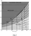
- the Mollier diagram shown in Figure 7 can be considered.
- This diagram is a graphical representation of the changes in liquid-gaseous state of water at a surface as a function of temperature (in “°C” along the horizontal axis) and absolute humidity (in “g water / kg dry air” along the vertical axis).
- the temperature and humidity define a saturation of gaseous water in the air of 50%.
- the temperature decreases, for example to the temperature defined by point “A”
- a phenomenon of water condensation occurs, and liquid water forms on the surface considered (this is the dew point).
- the time t c , the electrical resistance R th and the fixed current then make it possible to determine the power P th required to defog the surface under particular temperature and humidity conditions.
- the regulation method according to the present invention therefore makes it possible to optimize the thermal power necessary for defrosting and demisting a support 200.
- the switching on and off of the resistive element depending on the possible formation of frost or mist on the support is carried out in a manner automatic on objective and repeatable criteria, and therefore no longer require the intervention of an operator.
- first transparent layer 110 and a second transparent layer 120 makes it possible to envisage the implementation of the resistive element according to the present invention also for defrosting a windshield of a motor vehicle, or a visor of a mask or a helmet.
- the defrosting sequence b) also comprises a step b3) of determining the electrical resistance R of the first layer 110 as a function of the gate potential Vg likely to be applied to the second layer 120.
- step b3) comprises an acquisition by the computer 400 of the voltage V at two terminals of the first layer crossed by a known electric current I, and for different values of gate potential Vg.
- the present invention also relates to a computer program, which when executed by a computer 400, causes the latter to implement the method of regulating the resistive element 100.
- the present invention also relates to the resistive element for defrosting and/or demisting a support, and controlled by the computer 400 on which the computer program is stored.
- the resistive element comprises the stack of layers 101 formed by the first layer 110 and the second layer 120 separated by the insulating layer 130.
- the first layer may comprise a two-dimensional material with variable resistance under the effect of an electric field and is intended to dissipate the adjusted thermal power P th
- the second layer may comprise a resistive material and is intended, when subjected to an electric potential V g , to impose an electric field on the first layer.
- the thicknesses of the first 110 and the second 120 layer can be adjusted so that the transparency of the resistive element in the visible range is greater than 80%.
- the resistive material may also comprise a two-dimensional material with variable resistance under the effect of an electric field.
- the resistive element is formed on an exposed face of the support.
- the support comprises two layers, called support layers, between which the resistive element is inserted.
- the support may be transparent in the visible range, in particular the support may comprise either a window of a motor vehicle, or a visor of a helmet, or a visor of a mask.
- Figures 7a to 7e represent an example of a method of manufacturing the resistive element in a support 200 provided with two support layers 201 and 202.
- the support 200 is in particular a windshield.
- the method comprises a first step 1) of forming the second layer 120 on one of the support layers, for example the support layer 202.
- the second layer can include graphene by dispersion (“spray coating” according to Anglo-Saxon terminology).
- the first step 1) is followed by a second step 2) of forming the insulating layer 130.
- the insulating layer 130 may comprise SiO 2 , HfO 2 and be formed by a vapor deposition technique (“CVD” or “Chemical Vapor Deposition” according to Anglo-Saxon terminology).
- a third step 3) of forming the first layer 110 covering the insulating layer 130 is then carried out according to the same methods as the first step.
- Source contacts 111 and drain contacts 112 on the one hand, and gate contacts 121 on the other hand, are formed, respectively on the first layer 110 and on the second layer 120 during a fourth step 4).
- Step 4) is then followed by a fifth step 5) of covering the first layer 110 with the support layer 201.
- one or more temperature and/or humidity sensors can be formed on the support.
- the resistive element 100, and possibly the sensor(s) 300 can be interfaced with the computer 400.
- the computer 400 may in particular comprise an execution unit 401, intended to implement the sequence b), and a data processing unit 402 intended to collect the temperature and the humidity level measured by the sensor(s) 300, and determine the conditions for implementing the defrosting and/or demisting sequence.
- an execution unit 401 intended to implement the sequence b
- a data processing unit 402 intended to collect the temperature and the humidity level measured by the sensor(s) 300, and determine the conditions for implementing the defrosting and/or demisting sequence.
Landscapes
- Engineering & Computer Science (AREA)
- Physics & Mathematics (AREA)
- General Physics & Mathematics (AREA)
- Automation & Control Theory (AREA)
- Mechanical Engineering (AREA)
- Investigating Or Analyzing Materials By The Use Of Electric Means (AREA)
- Investigating Or Analyzing Materials Using Thermal Means (AREA)
Claims (10)
- Regelverfahren mittels eines Rechners für ein Widerstandselement (100), das zum Enteisen und/oder Entnebeln eines Trägers (200) angeordnet ist, wobei das Verfahren Folgendes umfasst:a) eine Überwachungsschleife für die Temperatur T und den Feuchtigkeitsgehalt H am Träger (200);b) eine Enteisungs- und/oder Entnebelungssequenz, die, solange die von der Überwachungsschleife überwachte Temperatur T und der Feuchtigkeitsgehalt H a) auf das Fehlen von Eis oder Nebel auf dem Träger (200) hindeuten, das Widerstandselement (100) inaktiv hält und andernfalls in einem Schritt b2) den Fluss eines Stroms I in dem Widerstandselement (100) steuert, so dass dieses eine thermische Leistung Pth abführt, die in Abhängigkeit von der Temperatur T und dem Feuchtigkeitsgehalt H angepasst ist und das Enteisen oder Entnebeln des Trägers (200) nach einer vorbestimmten Zeit Dp ermöglicht, vorteilhafterweise weniger als 2 Sekunden,wobei die Enteisungssequenz b) Folgendes umfasst:b1) einen Schritt zur Bestimmung der Wärmeleistung Pth auf der Grundlage der Temperatur T und des Feuchtigkeitsgehalts H, die von der Schleife a) überwacht werden, der vor Schritt b2) durchgeführt wird,dadurch gekennzeichnet, dassdas Widerstandselement (100) einen Stapel von Schichten (101) umfasst, der durch eine erste Schicht (110) und eine zweite Schicht (120) gebildet ist, die durch eine Isolierschicht (130) getrennt sind, wobei die erste Schicht (110) ein zweidimensionales Material mit variablem Widerstand unter der Wirkung eines elektrischen Feldes umfasst und dazu bestimmt ist, die angepasste thermische Leistung Pth abzuführen, während die zweite Schicht (120) ein ohmsches Material umfasst und dazu bestimmt ist, sobald sie einem elektrischen Potenzial Vg ausgesetzt ist, der ersten Schicht (110) ein elektrisches Feld aufzuprägen, wobei die Enteisungssequenz b) auch einen vor dem Schritt b1) durchgeführten Schritt b3) zur Bestimmung des Widerstands R der ersten Schicht (110), durch die ein bekannter Strom I fließt, als Funktion der an die zweite Schicht (120) angelegten Potentiale Vg umfasst.
- Verfahren nach Anspruch 1, wobei die Überwachungsschleife a) Folgendes umfasst:a1) einen Schritt der Messung der Temperatur T und der Luftfeuchtigkeit H;a2) einen Schritt zur Bestimmung des Vorhandenseins oder Nichtvorhandenseins von Eis oder Nebel auf dem Träger (200) in Abhängigkeit von der in Schritt a1) gemessenen Temperatur T und dem Feuchtigkeitsgehalt H.
- Verfahren nach Anspruch 1 oder 2, wobei die Überwachungsschleife a) periodisch, vorteilhafterweise alle zwei Sekunden, ausgeführt wird.
- Verfahren nach einem der Ansprüche 1 bis 3, wobei der Schritt b1) mittels eines Diagramms ausgeführt wird, das in einem Speicherplatz des Rechners (400) gespeichert ist und die Bestimmung der thermischen Leistung Pth in Abhängigkeit von der Temperatur T und dem Feuchtigkeitsgehalt H ermöglicht.
- Verfahren nach einem der Ansprüche 1 bis 4, wobei die Anpassung der thermischen Leistung Pth eine Anpassung des elektrischen Potenzials Vg umfasst.
- Verfahren nach einem der Ansprüche 1 bis 5, wobei die Überwachungsschleife a) auch mittels eines Temperatur- und Feuchtigkeitssensors (300) durchgeführt wird, der auf oder in dem Träger (200) angeordnet ist.
- Computerprogramm, das Anweisungen umfasst, die, wenn das Programm von einem Rechner (400) ausgeführt wird, dazu führen, dass dieses das Verfahren nach einem der Ansprüche 1 bis 6 umsetzt.
- Vorrichtung mit einem Widerstandselement (100), das zum Enteisen und/oder Entnebeln eines Trägers (200) angeordnet ist, und einem Rechner (400), auf dem das Computerprogramm nach Anspruch 7 gespeichert ist, wobei der Rechner (400) zur Regelung des Widerstandselements (100) bestimmt ist,
wobei das Widerstandselement (100) einen Stapel von Schichten umfasst, der durch eine erste Schicht (110) und eine zweite Schicht (120) gebildet ist, die durch eine Isolierschicht (130) getrennt sind, wobei die erste Schicht (110) ein zweidimensionales Material mit variablem Widerstand unter der Wirkung eines elektrischen Feldes umfasst und dazu bestimmt ist, die angepasste thermische Leistung Pth abzuführen, während die zweite Schicht (120) ein Widerstandsmaterial umfasst und dazu bestimmt ist, wenn sie einem elektrischen Potenzial Vg ausgesetzt ist, ein elektrisches Feld auf die erste Schicht (110) aufzuzwingen. - Vorrichtung nach Anspruch 8, wobei die Dicke der ersten und zweiten Schicht (120) so eingestellt ist, dass die Transparenz des Widerstandselements (100) im sichtbaren Bereich größer als 80 % ist.
- Vorrichtung nach Anspruch 8 oder 9, wobei das Widerstandsmaterial auch ein zweidimensionales Material mit variablem Widerstand unter Einwirkung eines elektrischen Feldes ist.
Applications Claiming Priority (1)
| Application Number | Priority Date | Filing Date | Title |
|---|---|---|---|
| FR1912031A FR3102636B1 (fr) | 2019-10-28 | 2019-10-28 | procédé de régulation d’un élément résistif destiné à dégivrer et/ou désembuer un support, et le dispositif associé |
Publications (2)
| Publication Number | Publication Date |
|---|---|
| EP3817509A1 EP3817509A1 (de) | 2021-05-05 |
| EP3817509B1 true EP3817509B1 (de) | 2025-06-25 |
Family
ID=69810995
Family Applications (1)
| Application Number | Title | Priority Date | Filing Date |
|---|---|---|---|
| EP20203056.5A Active EP3817509B1 (de) | 2019-10-28 | 2020-10-21 | Verfahren zur regulierung eines resistiven elementes, das zum auftauen und/oder entfrosten einer halterung dient, und entsprechende vorrichtung |
Country Status (3)
| Country | Link |
|---|---|
| US (1) | US12082314B2 (de) |
| EP (1) | EP3817509B1 (de) |
| FR (1) | FR3102636B1 (de) |
Families Citing this family (2)
| Publication number | Priority date | Publication date | Assignee | Title |
|---|---|---|---|---|
| CA3218449A1 (en) * | 2021-06-03 | 2022-12-08 | Gentex Corporation | Anti-condensation eyewear |
| GR1011040B (el) * | 2024-10-17 | 2025-09-22 | Divepro A.E., | Αντιθαμβωτικος μηχανισμος για μασκες προσωπου με διαφανες υλικο στο οπτικο πεδιο του χρηστη μεταξυ των ματιων του χρηστη και του εξωτερικου περιβαλλοντος |
Family Cites Families (17)
| Publication number | Priority date | Publication date | Assignee | Title |
|---|---|---|---|---|
| JPS5347131B2 (de) * | 1973-02-07 | 1978-12-19 | ||
| US4782216A (en) * | 1987-08-11 | 1988-11-01 | Monsanto Company | Electrically heatable laminated window |
| US7883609B2 (en) * | 1998-06-15 | 2011-02-08 | The Trustees Of Dartmouth College | Ice modification removal and prevention |
| US6470696B1 (en) * | 2001-09-18 | 2002-10-29 | Valerie Palfy | Devices and methods for sensing condensation conditions and for removing condensation from surfaces |
| KR101222639B1 (ko) | 2010-02-12 | 2013-01-16 | 성균관대학교산학협력단 | 그래핀을 이용한 유연성 투명 발열체 및 이의 제조 방법 |
| US8431869B2 (en) | 2010-06-02 | 2013-04-30 | GM Global Technology Operations LLC | Defrosting, defogging and de-icing structures |
| US8793103B2 (en) * | 2010-11-30 | 2014-07-29 | General Electric Company | Method and system for detection of machine operation state for monitoring purposes |
| DE102011121921A1 (de) * | 2011-12-22 | 2013-06-27 | Volkswagen Aktiengesellschaft | Anordnung zum Beheizen einer Scheibe eines Fahrzeugs sowie Fahrzeug mit einer solchen Anordnung |
| US8725349B2 (en) * | 2012-09-11 | 2014-05-13 | GM Global Technology Operations LLC | Rear defogger control strategy based on a number of vehicle occupants |
| EP3013119A1 (de) * | 2014-10-24 | 2016-04-27 | Centre National De La Recherche Scientifique | Transparente Heizvorrichtung mit Graphen-Film |
| JP6591181B2 (ja) * | 2015-03-16 | 2019-10-16 | 三菱航空機株式会社 | 風防装置、航空機、および風防ヒータの電力制御方法 |
| CN105539368A (zh) * | 2016-01-11 | 2016-05-04 | 上海烯旺信息科技有限公司 | 一种基于石墨烯技术的发热挡风玻璃系统 |
| KR101901353B1 (ko) * | 2017-01-26 | 2018-09-21 | 윤수현 | 그래핀 발열체를 이용한 차량용 오토 디포그 장치 |
| FR3066644B1 (fr) * | 2017-05-19 | 2019-07-05 | Commissariat A L'energie Atomique Et Aux Energies Alternatives | Dispositif electriquement conducteur, transparent ou semi-transparent, a base de nanofils metalliques et de nanoparticules de silice poreuse |
| US11229091B2 (en) * | 2018-05-30 | 2022-01-18 | Betterfrost Technologies, Inc. | Continuous resistance and proximity checking for high power deicing and defogging systems |
| US12031932B2 (en) * | 2018-09-05 | 2024-07-09 | Ppg Industries Ohio, Inc. | System and method for monitoring resistance of a conductive coating as an indicator of a condition of the conductive coating |
| US11639954B2 (en) * | 2019-05-29 | 2023-05-02 | Rosemount Aerospace Inc. | Differential leakage current measurement for heater health monitoring |
-
2019
- 2019-10-28 FR FR1912031A patent/FR3102636B1/fr active Active
-
2020
- 2020-10-19 US US17/073,575 patent/US12082314B2/en active Active
- 2020-10-21 EP EP20203056.5A patent/EP3817509B1/de active Active
Also Published As
| Publication number | Publication date |
|---|---|
| US12082314B2 (en) | 2024-09-03 |
| EP3817509A1 (de) | 2021-05-05 |
| US20210127454A1 (en) | 2021-04-29 |
| FR3102636B1 (fr) | 2021-12-03 |
| FR3102636A1 (fr) | 2021-04-30 |
Similar Documents
| Publication | Publication Date | Title |
|---|---|---|
| EP3817509B1 (de) | Verfahren zur regulierung eines resistiven elementes, das zum auftauen und/oder entfrosten einer halterung dient, und entsprechende vorrichtung | |
| US8745998B2 (en) | Methods and systems for controlling vehicle defrost units | |
| US10479322B2 (en) | Wiper control mechanism | |
| LU88657A1 (fr) | Vitrage chauffant et circuit de contrôle destiné à ce vitrage | |
| CN103444259A (zh) | 用于利用电气加热装置给透明玻璃除冰的方法和组件 | |
| EP0718165B1 (de) | Vorrichtung zur Entnebelung von Fahrzeugscheiben | |
| FR3066740A1 (fr) | Procede de commande d’un dispositif de degivrage et de desembuage de vehicule | |
| EP0782265A1 (de) | Verfahren und Vorrichtung zum Schutz einer Elemente mit einstellbarer Impedanz zur Steuerung der Versorgung eines Elektromotors, insbesondere eines Kraftfahrzeugs | |
| EP4230980B1 (de) | Verfahren zur ermittlung der externen umgebungstemperatur in einem ein photovoltaisches modul umfassenden system und korrespondierendes system | |
| EP2851246B1 (de) | Verfahren zur Erfassung der Position eines Wischarms einer Scheibenwischervorrichtung | |
| EP3790772B1 (de) | Vorrichtung zur fernwarnung über den verschleisszustand von mindestens einem wischblatt einer scheibenwischeranlage | |
| EP4522435B1 (de) | Verfahren und system zur regelung des beschlagens auf der innenfläche mindestens einer verglasungseinheit eines fahrzeugs | |
| EP2004431A1 (de) | Verfahren und vorrichtung zur verwaltung der energieversorgung für eine elektrochrome glasdachplatte für ein kraftfahrzeug | |
| FR2934343A3 (fr) | Commande d'un systeme de freinage decouple pour vehicule automobile | |
| EP3335947B1 (de) | Wischersystem für kraftfahrzeug | |
| WO2018077757A1 (fr) | Dispositif d'essuyage pour vitre de vehicule automobile comprenant un balai d'essuie-glace et un film piezo-electrique | |
| FR2775452A1 (fr) | Procede et dispositif de commande du rechauffage d'un retroviseur de vehicule automobile | |
| WO2020057817A1 (fr) | Détection de neige sur une surface vitrée d'un véhicule automobile | |
| FR2789035A1 (fr) | Procede pour prevenir la formation de givre sur le pare- brise d'un vehicule automobile par detection des conditions de formation du givre | |
| WO2024079259A1 (fr) | Unité de protection et ensemble de détection pour véhicule automobile | |
| FR3152770A1 (fr) | Chauffage de balai d'essuie-glace notamment de véhicule automobile avec un logement pour le balai d'essuie-glace | |
| EP3172512B1 (de) | Verfahren und system zum erkennen von eis | |
| FR3140841A1 (fr) | module de protection et ensemble de détection pour véhicule automobile | |
| CA3234166A1 (fr) | Systeme et procede de chauffage pour un circuit d'eau d'aeronef | |
| WO2014154393A1 (fr) | Dispositif de commande pour machine de chauffage, ventilation et climatisation |
Legal Events
| Date | Code | Title | Description |
|---|---|---|---|
| PUAI | Public reference made under article 153(3) epc to a published international application that has entered the european phase |
Free format text: ORIGINAL CODE: 0009012 |
|
| STAA | Information on the status of an ep patent application or granted ep patent |
Free format text: STATUS: REQUEST FOR EXAMINATION WAS MADE |
|
| 17P | Request for examination filed |
Effective date: 20201021 |
|
| AK | Designated contracting states |
Kind code of ref document: A1 Designated state(s): AL AT BE BG CH CY CZ DE DK EE ES FI FR GB GR HR HU IE IS IT LI LT LU LV MC MK MT NL NO PL PT RO RS SE SI SK SM TR |
|
| STAA | Information on the status of an ep patent application or granted ep patent |
Free format text: STATUS: EXAMINATION IS IN PROGRESS |
|
| 17Q | First examination report despatched |
Effective date: 20220920 |
|
| RAP3 | Party data changed (applicant data changed or rights of an application transferred) |
Owner name: COMMISSARIAT A L'ENERGIE ATOMIQUE ET AUX ENERGIESALTERNATIVES |
|
| GRAP | Despatch of communication of intention to grant a patent |
Free format text: ORIGINAL CODE: EPIDOSNIGR1 |
|
| STAA | Information on the status of an ep patent application or granted ep patent |
Free format text: STATUS: GRANT OF PATENT IS INTENDED |
|
| INTG | Intention to grant announced |
Effective date: 20250207 |
|
| GRAS | Grant fee paid |
Free format text: ORIGINAL CODE: EPIDOSNIGR3 |
|
| GRAA | (expected) grant |
Free format text: ORIGINAL CODE: 0009210 |
|
| STAA | Information on the status of an ep patent application or granted ep patent |
Free format text: STATUS: THE PATENT HAS BEEN GRANTED |
|
| AK | Designated contracting states |
Kind code of ref document: B1 Designated state(s): AL AT BE BG CH CY CZ DE DK EE ES FI FR GB GR HR HU IE IS IT LI LT LU LV MC MK MT NL NO PL PT RO RS SE SI SK SM TR |
|
| REG | Reference to a national code |
Ref country code: GB Ref legal event code: FG4D Free format text: NOT ENGLISH |
|
| REG | Reference to a national code |
Ref country code: CH Ref legal event code: EP |
|
| REG | Reference to a national code |
Ref country code: DE Ref legal event code: R096 Ref document number: 602020053218 Country of ref document: DE |
|
| REG | Reference to a national code |
Ref country code: CH Ref legal event code: EP |
|
| REG | Reference to a national code |
Ref country code: IE Ref legal event code: FG4D Free format text: LANGUAGE OF EP DOCUMENT: FRENCH |
|
| PG25 | Lapsed in a contracting state [announced via postgrant information from national office to epo] |
Ref country code: FI Free format text: LAPSE BECAUSE OF FAILURE TO SUBMIT A TRANSLATION OF THE DESCRIPTION OR TO PAY THE FEE WITHIN THE PRESCRIBED TIME-LIMIT Effective date: 20250625 |
|
| REG | Reference to a national code |
Ref country code: LT Ref legal event code: MG9D |
|
| PG25 | Lapsed in a contracting state [announced via postgrant information from national office to epo] |
Ref country code: NO Free format text: LAPSE BECAUSE OF FAILURE TO SUBMIT A TRANSLATION OF THE DESCRIPTION OR TO PAY THE FEE WITHIN THE PRESCRIBED TIME-LIMIT Effective date: 20250925 Ref country code: GR Free format text: LAPSE BECAUSE OF FAILURE TO SUBMIT A TRANSLATION OF THE DESCRIPTION OR TO PAY THE FEE WITHIN THE PRESCRIBED TIME-LIMIT Effective date: 20250926 |
|
| PG25 | Lapsed in a contracting state [announced via postgrant information from national office to epo] |
Ref country code: BG Free format text: LAPSE BECAUSE OF FAILURE TO SUBMIT A TRANSLATION OF THE DESCRIPTION OR TO PAY THE FEE WITHIN THE PRESCRIBED TIME-LIMIT Effective date: 20250625 |
|
| PG25 | Lapsed in a contracting state [announced via postgrant information from national office to epo] |
Ref country code: HR Free format text: LAPSE BECAUSE OF FAILURE TO SUBMIT A TRANSLATION OF THE DESCRIPTION OR TO PAY THE FEE WITHIN THE PRESCRIBED TIME-LIMIT Effective date: 20250625 |
|
| PG25 | Lapsed in a contracting state [announced via postgrant information from national office to epo] |
Ref country code: RS Free format text: LAPSE BECAUSE OF FAILURE TO SUBMIT A TRANSLATION OF THE DESCRIPTION OR TO PAY THE FEE WITHIN THE PRESCRIBED TIME-LIMIT Effective date: 20250925 |
|
| PG25 | Lapsed in a contracting state [announced via postgrant information from national office to epo] |
Ref country code: LV Free format text: LAPSE BECAUSE OF FAILURE TO SUBMIT A TRANSLATION OF THE DESCRIPTION OR TO PAY THE FEE WITHIN THE PRESCRIBED TIME-LIMIT Effective date: 20250625 |
|
| REG | Reference to a national code |
Ref country code: NL Ref legal event code: MP Effective date: 20250625 |
|
| PG25 | Lapsed in a contracting state [announced via postgrant information from national office to epo] |
Ref country code: NL Free format text: LAPSE BECAUSE OF FAILURE TO SUBMIT A TRANSLATION OF THE DESCRIPTION OR TO PAY THE FEE WITHIN THE PRESCRIBED TIME-LIMIT Effective date: 20250625 |
|
| PG25 | Lapsed in a contracting state [announced via postgrant information from national office to epo] |
Ref country code: PT Free format text: LAPSE BECAUSE OF FAILURE TO SUBMIT A TRANSLATION OF THE DESCRIPTION OR TO PAY THE FEE WITHIN THE PRESCRIBED TIME-LIMIT Effective date: 20251027 |
|
| REG | Reference to a national code |
Ref country code: AT Ref legal event code: MK05 Ref document number: 1808033 Country of ref document: AT Kind code of ref document: T Effective date: 20250625 |
|
| PG25 | Lapsed in a contracting state [announced via postgrant information from national office to epo] |
Ref country code: IS Free format text: LAPSE BECAUSE OF FAILURE TO SUBMIT A TRANSLATION OF THE DESCRIPTION OR TO PAY THE FEE WITHIN THE PRESCRIBED TIME-LIMIT Effective date: 20251025 |
|
| PGFP | Annual fee paid to national office [announced via postgrant information from national office to epo] |
Ref country code: DE Payment date: 20251020 Year of fee payment: 6 |
|
| PGFP | Annual fee paid to national office [announced via postgrant information from national office to epo] |
Ref country code: GB Payment date: 20251029 Year of fee payment: 6 |
|
| PG25 | Lapsed in a contracting state [announced via postgrant information from national office to epo] |
Ref country code: AT Free format text: LAPSE BECAUSE OF FAILURE TO SUBMIT A TRANSLATION OF THE DESCRIPTION OR TO PAY THE FEE WITHIN THE PRESCRIBED TIME-LIMIT Effective date: 20250625 Ref country code: SM Free format text: LAPSE BECAUSE OF FAILURE TO SUBMIT A TRANSLATION OF THE DESCRIPTION OR TO PAY THE FEE WITHIN THE PRESCRIBED TIME-LIMIT Effective date: 20250625 |
|
| PGFP | Annual fee paid to national office [announced via postgrant information from national office to epo] |
Ref country code: FR Payment date: 20251024 Year of fee payment: 6 |
|
| PG25 | Lapsed in a contracting state [announced via postgrant information from national office to epo] |
Ref country code: CZ Free format text: LAPSE BECAUSE OF FAILURE TO SUBMIT A TRANSLATION OF THE DESCRIPTION OR TO PAY THE FEE WITHIN THE PRESCRIBED TIME-LIMIT Effective date: 20250625 |
|
| PG25 | Lapsed in a contracting state [announced via postgrant information from national office to epo] |
Ref country code: PL Free format text: LAPSE BECAUSE OF FAILURE TO SUBMIT A TRANSLATION OF THE DESCRIPTION OR TO PAY THE FEE WITHIN THE PRESCRIBED TIME-LIMIT Effective date: 20250625 |
|
| PG25 | Lapsed in a contracting state [announced via postgrant information from national office to epo] |
Ref country code: EE Free format text: LAPSE BECAUSE OF FAILURE TO SUBMIT A TRANSLATION OF THE DESCRIPTION OR TO PAY THE FEE WITHIN THE PRESCRIBED TIME-LIMIT Effective date: 20250625 |
|
| PG25 | Lapsed in a contracting state [announced via postgrant information from national office to epo] |
Ref country code: SK Free format text: LAPSE BECAUSE OF FAILURE TO SUBMIT A TRANSLATION OF THE DESCRIPTION OR TO PAY THE FEE WITHIN THE PRESCRIBED TIME-LIMIT Effective date: 20250625 |
|
| PG25 | Lapsed in a contracting state [announced via postgrant information from national office to epo] |
Ref country code: ES Free format text: LAPSE BECAUSE OF FAILURE TO SUBMIT A TRANSLATION OF THE DESCRIPTION OR TO PAY THE FEE WITHIN THE PRESCRIBED TIME-LIMIT Effective date: 20250625 |
|
| PG25 | Lapsed in a contracting state [announced via postgrant information from national office to epo] |
Ref country code: RO Free format text: LAPSE BECAUSE OF FAILURE TO SUBMIT A TRANSLATION OF THE DESCRIPTION OR TO PAY THE FEE WITHIN THE PRESCRIBED TIME-LIMIT Effective date: 20250625 |
|
| PG25 | Lapsed in a contracting state [announced via postgrant information from national office to epo] |
Ref country code: DK Free format text: LAPSE BECAUSE OF FAILURE TO SUBMIT A TRANSLATION OF THE DESCRIPTION OR TO PAY THE FEE WITHIN THE PRESCRIBED TIME-LIMIT Effective date: 20250625 |
|
| PG25 | Lapsed in a contracting state [announced via postgrant information from national office to epo] |
Ref country code: IT Free format text: LAPSE BECAUSE OF FAILURE TO SUBMIT A TRANSLATION OF THE DESCRIPTION OR TO PAY THE FEE WITHIN THE PRESCRIBED TIME-LIMIT Effective date: 20250625 |
|
| PLBE | No opposition filed within time limit |
Free format text: ORIGINAL CODE: 0009261 |
|
| STAA | Information on the status of an ep patent application or granted ep patent |
Free format text: STATUS: NO OPPOSITION FILED WITHIN TIME LIMIT |