EP3818352B1 - Procédé et système de détection de gaz inflammable - Google Patents
Procédé et système de détection de gaz inflammable Download PDFInfo
- Publication number
- EP3818352B1 EP3818352B1 EP19752580.1A EP19752580A EP3818352B1 EP 3818352 B1 EP3818352 B1 EP 3818352B1 EP 19752580 A EP19752580 A EP 19752580A EP 3818352 B1 EP3818352 B1 EP 3818352B1
- Authority
- EP
- European Patent Office
- Prior art keywords
- parameter
- flammable
- sensor
- limit
- prospective
- Prior art date
- Legal status (The legal status is an assumption and is not a legal conclusion. Google has not performed a legal analysis and makes no representation as to the accuracy of the status listed.)
- Active
Links
Images



Classifications
-
- F—MECHANICAL ENGINEERING; LIGHTING; HEATING; WEAPONS; BLASTING
- F24—HEATING; RANGES; VENTILATING
- F24F—AIR-CONDITIONING; AIR-HUMIDIFICATION; VENTILATION; USE OF AIR CURRENTS FOR SCREENING
- F24F11/00—Control or safety arrangements
- F24F11/30—Control or safety arrangements for purposes related to the operation of the system, e.g. for safety or monitoring
- F24F11/32—Responding to malfunctions or emergencies
- F24F11/36—Responding to malfunctions or emergencies to leakage of heat-exchange fluid
-
- G—PHYSICS
- G01—MEASURING; TESTING
- G01M—TESTING STATIC OR DYNAMIC BALANCE OF MACHINES OR STRUCTURES; TESTING OF STRUCTURES OR APPARATUS, NOT OTHERWISE PROVIDED FOR
- G01M3/00—Investigating fluid-tightness of structures
- G01M3/02—Investigating fluid-tightness of structures by using fluid or vacuum
- G01M3/04—Investigating fluid-tightness of structures by using fluid or vacuum by detecting the presence of fluid at the leakage point
-
- G—PHYSICS
- G01—MEASURING; TESTING
- G01M—TESTING STATIC OR DYNAMIC BALANCE OF MACHINES OR STRUCTURES; TESTING OF STRUCTURES OR APPARATUS, NOT OTHERWISE PROVIDED FOR
- G01M3/00—Investigating fluid-tightness of structures
- G01M3/02—Investigating fluid-tightness of structures by using fluid or vacuum
- G01M3/04—Investigating fluid-tightness of structures by using fluid or vacuum by detecting the presence of fluid at the leakage point
- G01M3/16—Investigating fluid-tightness of structures by using fluid or vacuum by detecting the presence of fluid at the leakage point using electric detection means
-
- G—PHYSICS
- G01—MEASURING; TESTING
- G01M—TESTING STATIC OR DYNAMIC BALANCE OF MACHINES OR STRUCTURES; TESTING OF STRUCTURES OR APPARATUS, NOT OTHERWISE PROVIDED FOR
- G01M3/00—Investigating fluid-tightness of structures
- G01M3/02—Investigating fluid-tightness of structures by using fluid or vacuum
- G01M3/04—Investigating fluid-tightness of structures by using fluid or vacuum by detecting the presence of fluid at the leakage point
- G01M3/16—Investigating fluid-tightness of structures by using fluid or vacuum by detecting the presence of fluid at the leakage point using electric detection means
- G01M3/18—Investigating fluid-tightness of structures by using fluid or vacuum by detecting the presence of fluid at the leakage point using electric detection means for pipes, cables or tubes; for pipe joints or seals; for valves; for welds; for containers, e.g. radiators
Definitions
- the present invention relates to a method for monitoring for leakage of flammable compounds and to a related system.
- Exemplary embodiments pertain to the art of gas monitoring, and more specifically to detection of flammable gases from sources such as heating & cooling and refrigerant systems.
- Gas sensors have been used in various applications such as process monitoring and control and safety monitoring. As the compounds can also be flammable or explosive, gas detection sensors have also been used for leak detection where such compounds are used or manufactured.
- Various types of sensors have been used or proposed, including but not limited to metal oxide semiconductor (MOS) sensors, non-dispersive infrared detector (NDIR) sensors, pellistor (pelletized resistor) sensors, ultrasonic sensors, high-temperature solid electrolytes that are permeable to oxygen ions, and electrochemical cells.
- MOS metal oxide semiconductor
- NDIR non-dispersive infrared detector
- pellistor pellistor
- ultrasonic sensors high-temperature solid electrolytes that are permeable to oxygen ions, and electrochemical cells.
- US 2017/045474 discloses a method for leak detection of flammable refrigerants using a first sensing element and a second sensing element.
- US 2017/370605 A1 discloses a method for determining a refrigerant leakage with either a temperature sensor, a first refrigerant sensor or a second refrigerant sensor.
- EP 3 584 521 A1 a document falling under Art. 54(3) EPC, discloses a refrigerant leak sensor configured to detect a refrigerant leak at the usage-side refrigeration circuit and a refrigerant state sensor near the compressor to determine erroneous detection.
- the invention provides a method for monitoring for leakage of flammable compounds according to claim 1.
- the invention provides a monitoring system for detecting leakage of flammable compounds according to claim 2.
- the invention provides an air conditioning or heat pump system according to claim 3.
- the refrigerant has a class 2 or class 2L or class 3 flammability rating according to ASHRAE 34-2016.
- the sensors are disposed in a conduit on the conditioned air flow path comprising an inlet and an outlet, and the first and second sensors are disposed in the conduit with the second sensor downstream from the first sensor with respect to a direction of flow from the inlet to the outlet.
- measurements of the first parameter are indicative of the presence and concentration of a flammable compound.
- measurements of the first parameter are provided by a sensor selected from an ultrasound sensor, an infrared absorbance sensor, an electrochemical sensor, or a MOS sensor.
- the second parameter includes temperature
- the second parameter includes humidity.
- the second parameter includes gas flow.
- the space around the potential leak source is an enclosed space.
- pellistor sensors are prone to false alarms due to cross-sensitivity.
- NDIR sensors can provide good selectivity, but are expensive for high volume applications.
- Electrochemical sensors rely on redox reactions involving tested gas components at electrodes separated by an electrolyte that produce or affect electrical current in a circuit connecting the electrodes.
- solid state electrochemical sensors can be prone to nuisance alarms due to poor selectivity.
- solid state electrochemical sensors testing for combustible hydrocarbons may utilize solid electrolytes formed from ceramics such as perovskite, which can require high temperatures (typically in excess of 500°C) that render them impractical for many applications that require long lifetime.
- Some electrochemical sensors that operate at lower temperatures e.g., carbon monoxide sensors, hydrogen sulfide sensors
- MOS sensors rely on interaction between gas test components such as hydrogen sulfide or hydrocarbons with adsorbed oxygen on the metal oxide semiconductor surface.
- gas test components such as hydrogen sulfide or hydrocarbons with adsorbed oxygen on the metal oxide semiconductor surface.
- the metal oxide semiconductor adsorbs atmospheric oxygen at the surface, and this adsorbed oxygen captures free electrons from the metal oxide semiconductor material, resulting in a measurable level of base resistance of the semiconductor at a relatively high level.
- reducing or combustible gas test components such as hydrocarbons or hydrofluorocarbons (HFCs)
- the gas test component interacts with the adsorbed oxygen, causing it to release free electrons back to the semiconductor material, resulting in a measurable decrease in resistance that can be correlated with a measured level of test gas component.
- HFCs hydrofluorocarbons
- Ultrasonic sensors can detect for the presence of gas components based on the dependence of speed of sound on gas compositions, but can be susceptible to false alarms because environment conditions such as temperature and moisture content can also affect the output as do gas compositions. More importantly, the speed-of-sound based detection can be relatively non-selective, hence can potentially lead to false alarms.
- the systems and methods described herein include first and second sensors, and additional sensors.
- the sensors can be disposed as separate sensor assemblies or can be combined into a unitary sensor assembly with multiple sensor components.
- One of the sensors, or a constituent component in a sensor measures a parameter indicative of a presence of flammable gas.
- Such a sensor or a sensing mechanism can include, but is not limited to, conductance measurement e.g., metal oxide sensors or speed of sound measurement, e.g. ultrasonic sensors.
- the architecture of the core elements of a detection system 100 with multiple indicators is illustrated schematically in FIG. 1 . As shown in FIG.
- the system 100 includes a first sensing element 102 for monitoring a primary condition parameter or parameters of a sample from the surrounding atmosphere indicative of the presence of flammable compounds in a space 104 around a potential leak source of a flammable compound.
- the first sensing element 102 can measure a primary parameter that is also indicative of a concentration of flammable compounds or indicative of a change in concentration of flammable compounds.
- the first sensing element 102 for measuring the primary parameter(s) can be selected from ultrasound sensors, infrared absorbance sensors, electrochemical sensors, or MOS sensors. As further shown in FIG.
- the system 100 also includes one or more sensing elements to measure multiple 'second' parameters, which can also be referred to as secondary and tertiary, etc. parameters (in this case a second sensing element 106 and a third sensing element 108), and which operates on a different sensing mechanism from that of the primary parameter.
- Secondary or tertiary parameters can include any of the above primary parameters that can directly or indirectly measure gas phase composition, or parameters such as environmental parameters (e.g., temperature and humidity) that may not be sufficiently selective by themselves for detection of flammable compounds. Secondary environmental parameters can be examined for a rate of change. The output of the system is pertinent to whether flammable gas is present, and hence that a system leak has occurred.
- a controller e.g., an electronic control unit (ECU) 110, which can utilize software and/or firmware logic to examine the primary and auxiliary indicators physically measured by the aforementioned sensing components.
- ECU electronice control unit
- a primary parameter is based the detection of gas compositions or the change in gas compositions and the auxiliary parameters are related to environment conditions that indirectly reflect leaks, particularly those involves phase changes such as liquid refrigerant vaporization.
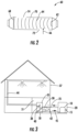
- FIG. 2 An example embodiment of an ultrasonic sensor 60 is shown in FIG. 2 .
- a sound emitter/receiver 62 directs sound waves 64 through a test gas sample 66 to another emitter/receiver 68.
- the ultrasound transceivers can be mounted at two ends of a gas sampling conduit 70. Gas ports 72 and 74 are provided on the conduit 70 to allow gas to transport into the space for determining the change in atmosphere composition.
- a measured speed of sound through the gas can be calculated based on elapsed time for the signal, and compared to stored data such as a look-up table based for example on calibrated test data from samples of known flammable gas concentrations, and a determination made of flammable gas concentration in the sample.
- a sensing element for a secondary indicator can be mounted inside the conduit 70, or exterior to the conduit 70 to detect concomitant evidence associated with a leak, or located on other system components such as on a printed circuit board assembly (PCBA).
- PCBA printed circuit board assembly
- a heat transfer system includes a compressor 10 which pressurizes the refrigerant or heat transfer fluid in its gaseous state, which both heats the fluid and provides pressure to circulate it throughout the system.
- the hot pressurized gaseous heat transfer fluid exiting from the compressor 10 flows through conduit 15 to heat rejection heat exchanger 20, which functions as a heat exchanger to transfer heat from the heat transfer fluid to the surrounding environment, resulting in condensation of the hot gaseous heat transfer fluid to a pressurized moderate temperature liquid.
- the liquid heat transfer fluid exiting from the heat rejection heat exchanger 20 flows through conduit 25 to expansion valve 30, where the pressure is reduced.
- the reduced pressure liquid heat transfer fluid exiting the expansion valve 30 flows to fan coil unit 35 inside the building 37, which includes fan 38 and heat absorption heat exchanger 40 (e.g., an evaporator), which functions as a heat exchanger to absorb heat from the surrounding environment and boil the heat transfer fluid.
- heat absorption heat exchanger 40 heat is absorbed by the refrigerant from a conditioned air flow path that includes a return air conduit 42 that returns air from the conditioned air space inside the building 37 and a supply air conduit 44 that supplies conditioned air to the conditioned air space inside the building 37.
- Gaseous heat transfer fluid exiting the heat rejection heat exchanger 40 flows through conduit 45 to the compressor 10, thus completing the heat transfer fluid loop.
- the heat transfer system can transfer heat from the environment surrounding to the evaporator 40 to the environment surrounding the heat rejection heat exchanger 20.
- the thermodynamic properties of the heat transfer fluid allow it to reach a high enough temperature when compressed so that it is greater than the environment surrounding the condenser 20, allowing heat to be transferred to the surrounding environment.
- the thermodynamic properties of the heat transfer fluid should also have a boiling point at its post-expansion pressure that allows the environment surrounding the heat rejection heat exchanger 20 to provide heat at a temperature to vaporize the liquid heat transfer fluid.
- the heat transfer system further includes sensor pack 50, which is placed in the indoor section of the system to detect refrigerant leaks that can potential pose risks to the building and occupants.
- the sensor with auxiliary sensing elements besides the primary leak detection sensor is place in the unit to allow for monitoring the gas phase composition and environment conditions.
- a sensor in the sensor pack 50 can be operated to measure a primary parameter indicative of presence of a flammable gas.
- the other sensing element(s) in the sensor pack 50 can be operated to measure a secondary parameter(s) such as temperature, and/or humidity, and/or gas flow in the enclosed space.
- FIG. 4 A protocol for operating a sensing device with multiple indicators to detect flammable gas leaks and to avoid false alarms is shown in FIG. 4 .
- the determination of refrigerant leaks is enhanced by the method based on multiple indicators as illustrated in the architecture of the sensing system such as shown in FIG. 1 , and related logic as shown in FIG. 4 .
- the embodiment of FIG. 4 shows logic based on the sensing system of FIG. 1 .
- a sensing system in detection mode 202 generates sensing output from the first sensing element 102 that is examined at decision block 204 to assess whether the primary parameter or indicator (e.g., a parameter related to gas phase composition flammable content) has exceeded a first or lower limit.
- the primary parameter or indicator e.g., a parameter related to gas phase composition flammable content
- the routine proceeds to decision block 206 where output from a second sensing element 106 and/or third sensing element 108 is examined for a rate of change.
- the rate of change of a secondary indicator can in some cases manifest the effects of refrigerant leaks such as sudden temperature decreases and/or humidity variations due to displacement of moisture. If the rate of change of the secondary indicator(s) does not show sufficient changes to warrant determination of leak at block 206, then the routine proceeds to block 208 where the primary indicator is examined against a second or upper limit. If the primary indicator is below this second or upper limit, then a false alarm is registered at block 210 and the system returns to sensor detection mode at block 202.
- the routine proceeds to block 212, where leak mitigation actions (e.g., introduce airflow by a fan) are taken by the system, followed by a system check at decision block 214 in which the primary indicator is measured and compared to a third limit (e.g., a safety limit). If the primary indicator is below the third limit, the mitigation actions are deemed effective and the sensor is reset at block 216 and returned to detection mode at block 202.
- leak mitigation actions e.g., introduce airflow by a fan
- the system is put into a safe mode at block 218 in which mitigation actions are continued, and a sensor fault is registered at block 220.
- the leak mitigation actions are taken by the system at block 212 where primary indicator will be continually monitored until it drops below the lowest (safe) limit, namely the third limit. If the primary indicator confirms that the flammable gas concentration has decreased to a safe level, and sensor will be reset at block 216. However, if the primary indicator fails to indicate expected trend resulting from flammable gas dissipation, a sensor fault likely has occurred and a notification on sensor fault will be registered in the system at block 220. If the primary indicator does not exceed the upper (third) limit expected from more dramatic leaks, a false alarm can be registered at block 216 and sensor detection mode can continue.
- FIG. 5 plots flammable mass concentration (primary indicator), temperature (secondary indicator), and relative humidity (tertiary indicator) versus time, under conditions of a controlled introduction of a flammable compound in a simulated leak.
- primary indicator flammable mass concentration
- secondary indicator temperature
- tertiary indicator relative humidity
Landscapes
- Engineering & Computer Science (AREA)
- Physics & Mathematics (AREA)
- General Physics & Mathematics (AREA)
- Chemical & Material Sciences (AREA)
- Combustion & Propulsion (AREA)
- Mechanical Engineering (AREA)
- General Engineering & Computer Science (AREA)
- Examining Or Testing Airtightness (AREA)
Claims (11)
- Un procédé de surveillance des fuites de composés inflammables, comprenant :la mesure d'un premier paramètre indicatif de la présence de composés inflammables dans un espace autour d'une source de fuite potentielle d'un composé inflammable ;la détermination d'une présence prospective du composé inflammable sur la base d'une mesure du premier paramètre dépassant une première limite (204) ; etla mesure d'un deuxième paramètre dans l'espace autour de la source de fuite potentielle, où le deuxième paramètre étant une propriété physique du gaz dans l'espace (104) autour de la source de fuite potentielle, et où le deuxième paramètre étant sélectionné parmi une température, une humidité, une pression ou un débit de gaz ;caractérisé par :la mesure d'un troisième paramètre ou d'une pluralité de paramètres supplémentaires, où le troisième ou la pluralité de paramètres supplémentaires étant choisis parmi la température, le niveau d'humidité, la pression ou le débit de gaz ; etla caractérisation de la présence prospective du composé inflammable déterminée par la mesure du premier paramètre, en conjonction avec la mesure du deuxième paramètre et du troisième paramètre ou de la pluralité de paramètres supplémentaires, comme une présence réelle du composé inflammable (212) ou comme une fausse alarme (210),où la caractérisation comprend la caractérisation de la présence prospective comme une présence réelle du composé inflammable lorsqu'un taux de changement du deuxième paramètre et/ou du troisième paramètre ou de plusieurs paramètres supplémentaires dépasse une quatrième limite (206),où la caractérisation comprend la caractérisation de la présence prospective comme une présence réelle du composé inflammable lorsque la mesure du premier paramètre est supérieure à une seconde limite (208), etoù la caractérisation comprend la caractérisation de la présence prospective comme une fausse alarme lorsque les deux critères suivants sont vrais : a) le taux de changement du deuxième paramètre et/ou du troisième paramètre ou de la pluralité de paramètres supplémentaires ne dépasse pas la quatrième limite (206), et b) la mesure du premier paramètre est inférieure à la deuxième limite (208).
- Un système de surveillance pour détecter les fuites de composés inflammables, comprenant :un premier capteur (102) configuré pour mesurer un premier paramètre indicatif de la présence de composés inflammables dans un espace autour d'une source de fuite potentielle d'un composé inflammable ; etun deuxième capteur (106) pour mesurer un deuxième paramètre dans l'espace autour de la source de fuite potentielle, où le deuxième paramètre étant une propriété physique du gaz dans l'espace (104) autour de la source de fuite potentielle, et où le deuxième paramètre étant sélectionné parmi une température, une humidité, une pression ou un débit de gaz ;caractérisé par :le système est configuré pour mesurer un troisième paramètre ou d'une pluralité de paramètres, où le troisième ou la pluralité de paramètres supplémentaires étant choisis parmi la température, le niveau d'humidité, la pression ou le débit de gaz ; etun contrôleur (110) est configuré pour caractériser la présence prospective du composé inflammable déterminée par la mesure du premier paramètre, en conjonction avec la mesure du deuxième paramètre et du troisième paramètre ou de la pluralité de paramètres supplémentaires, comme une présence réelle du composé inflammable ou comme une fausse alarme,où le contrôleur (110) est configuré pour caractériser la présence prospective comme une présence réelle du composé inflammable lorsqu'un taux de changement du deuxième paramètre et/ou du troisième paramètre ou de plusieurs paramètres supplémentaires dépasse une quatrième limite,où le contrôleur (110) est configuré pour caractériser la présence prospective comme une présence réelle du composé inflammable lorsque la mesure du premier paramètre est supérieure à une seconde limite, etoù le contrôleur (110) est configuré pour caractériser la présence prospective comme une fausse alarme lorsque les deux critères suivants sont vrais : a) le taux de changement du deuxième paramètre et/ou du troisième paramètre ou de la pluralité de paramètres supplémentaires ne dépasse pas la quatrième limite, et b) la mesure du premier paramètre est inférieure à la deuxième limite.
- Un système de climatisation ou de pompe à chaleur, comprenantun premier échangeur de chaleur (20) comprenant un trajet d'écoulement d'air conditionné sur un premier côté de l'échangeur de chaleur, et un trajet d'écoulement de réfrigérant comprenant un réfrigérant inflammable sur un second côté de l'échangeur de chaleur en communication thermique avec le premier côté ;un trajet d'écoulement de fluide fermé comprenant le réfrigérant inflammable reliant le trajet d'écoulement de réfrigérant du premier échangeur de chaleur à un second échangeur de chaleur (40) en communication thermique avec une source de chaleur externe ou un dissipateur de chaleur ; etun système de surveillance tel que revendiqué dans la revendication 2.
- Un système selon la revendication 2 ou 3, dans lequel le réfrigérant a un indice d'inflammabilité de classe 2 ou de classe 2L ou de classe 3 selon ASHRAE 34-2016.
- Le système selon les revendications 2, 3 ou 4, dans lequel les capteurs (102, 106) sont disposés dans un conduit sur le trajet d'écoulement d'air conditionné comprenant une entrée et une sortie, et les premier et deuxième capteurs sont disposés dans le conduit avec le deuxième capteur en aval du premier capteur par rapport à une direction d'écoulement de l'entrée à la sortie.
- Un système selon l'une des revendications de 2 à 5, dans lequel les mesures du premier paramètre indiquent la présence et la concentration d'un composé inflammable.
- Un système selon l'une des revendications de 2 à 6, dans lequel les mesures du premier paramètre sont fournies par un capteur (102) sélectionné parmi un capteur à ultrasons (60), un capteur d'absorption infrarouge, un capteur électrochimique ou un capteur MOS.
- Un système selon l'une des revendications de 2 à 7, dans lequel le deuxième paramètre comprend la température.
- Un système selon l'une des revendications de 2 à 8, dans lequel le deuxième paramètre comprend l'humidité.
- Un système selon l'une des revendications de 2 à 9, dans lequel le deuxième paramètre comprend le débit de gaz.
- Le système selon l'une des revendications de 2 à 10, dans lequel l'espace (104) autour de la source de fuite potentielle est un espace clos.
Applications Claiming Priority (2)
| Application Number | Priority Date | Filing Date | Title |
|---|---|---|---|
| US201862694718P | 2018-07-06 | 2018-07-06 | |
| PCT/US2019/040300 WO2020010082A1 (fr) | 2018-07-06 | 2019-07-02 | Procédé et système de détection de gaz inflammable |
Publications (2)
| Publication Number | Publication Date |
|---|---|
| EP3818352A1 EP3818352A1 (fr) | 2021-05-12 |
| EP3818352B1 true EP3818352B1 (fr) | 2025-06-25 |
Family
ID=67587930
Family Applications (1)
| Application Number | Title | Priority Date | Filing Date |
|---|---|---|---|
| EP19752580.1A Active EP3818352B1 (fr) | 2018-07-06 | 2019-07-02 | Procédé et système de détection de gaz inflammable |
Country Status (4)
| Country | Link |
|---|---|
| US (1) | US11927354B2 (fr) |
| EP (1) | EP3818352B1 (fr) |
| CN (1) | CN112368558A (fr) |
| WO (1) | WO2020010082A1 (fr) |
Families Citing this family (17)
| Publication number | Priority date | Publication date | Assignee | Title |
|---|---|---|---|---|
| US11231198B2 (en) | 2019-09-05 | 2022-01-25 | Trane International Inc. | Systems and methods for refrigerant leak detection in a climate control system |
| DE102020101163A1 (de) * | 2020-01-20 | 2021-07-22 | Vaillant Gmbh | Sensorverschaltung |
| TWI756096B (zh) * | 2021-03-31 | 2022-02-21 | 兆勁科技股份有限公司 | 氣體外漏即時監控系統 |
| US12078368B2 (en) * | 2021-06-11 | 2024-09-03 | Honeywell International Inc. | Apparatuses, systems, and methods for gas leak detection |
| US11781767B2 (en) * | 2021-06-11 | 2023-10-10 | Honeywell International Inc. | Apparatuses, systems, and methods for gas leak detection |
| US11955668B2 (en) * | 2021-09-23 | 2024-04-09 | Haier Us Appliance Solutions, Inc. | Self-powered leak detection sensor |
| US12410926B2 (en) * | 2021-10-05 | 2025-09-09 | Carrier Corporation | Frost remidiation and frost sensor |
| US12487008B2 (en) | 2022-01-14 | 2025-12-02 | Trane International Inc. | Method of commissioning an HVAC system |
| US12117191B2 (en) | 2022-06-24 | 2024-10-15 | Trane International Inc. | Climate control system with improved leak detector |
| CN115235687B (zh) * | 2022-07-08 | 2025-05-30 | 国能国华(北京)燃气热电有限公司 | 燃机的检测方法、装置、电子设备、存储介质及系统 |
| USD1115569S1 (en) | 2022-11-28 | 2026-03-03 | Danfoss A/S | Gas detection sensor |
| USD1119637S1 (en) | 2023-02-09 | 2026-03-24 | Danfoss A/S | Gas detection sensor |
| JP7688282B2 (ja) * | 2023-08-01 | 2025-06-04 | ダイキン工業株式会社 | 庫内冷凍装置および冷蔵貯蔵庫 |
| USD1115570S1 (en) | 2023-08-15 | 2026-03-03 | Danfoss A/S | Gas detection sensor |
| EP4686898A1 (fr) | 2024-08-02 | 2026-02-04 | BDR Thermea Group B.V. | Contrôleur, méthode, produit de programme informatique et support non transitoire lisible par ordinateur pour surveiller les fuites de réfrigérant, pompe à chaleur comprenant le contrôleur |
| EP4686899A1 (fr) | 2024-08-02 | 2026-02-04 | BDR Thermea Group B.V. | Contrôleur, méthode, produit de programme informatique et support non transitoire lisible par ordinateur pour surveiller les fuites de réfrigérant, pompe à chaleur comprenant le contrôleur |
| WO2026027766A1 (fr) | 2024-08-02 | 2026-02-05 | Bdr Thermea Group B.V. | Pompe à chaleur dotée d'un système de détection de dysfonctionnement |
Citations (2)
| Publication number | Priority date | Publication date | Assignee | Title |
|---|---|---|---|---|
| US20170370605A1 (en) * | 2015-03-26 | 2017-12-28 | Mitsubishi Electric Corporation | Indoor unit for air-conditioning apparatus |
| EP3584521A1 (fr) * | 2017-02-14 | 2019-12-25 | Daikin Industries, Ltd. | Dispositif de réfrigération |
Family Cites Families (19)
| Publication number | Priority date | Publication date | Assignee | Title |
|---|---|---|---|---|
| US5889199A (en) | 1997-05-13 | 1999-03-30 | Jaesent Inc. | Portable leak detector |
| US6791088B1 (en) | 2001-05-04 | 2004-09-14 | Twin Rivers Engineering, Inc. | Infrared leak detector |
| WO2003027587A1 (fr) * | 2001-09-19 | 2003-04-03 | Kabushiki Kaisha Toshiba | Refrigerateur-congelateur, controleur pour refrigerateur-congelateur, et procede de determination de fuite de refrigerant |
| EP1522839B1 (fr) | 2003-10-08 | 2006-06-07 | INNOVA AirTech Instruments A/S | Détecteur à ultrason de fuite de gaz muni d'un système de test du détecteur |
| GR1006642B (el) | 2008-07-14 | 2009-12-22 | Θεοδωρος Ευθυμιου Ευθυμιου | Συστημα εμμεσης ανιχνευσης διαρροης ψυκτικων μεσων σε ψυκτικες διαταξεις επι μεσων μεταφορας |
| CN202904826U (zh) | 2012-11-30 | 2013-04-24 | 浙江海洋学院 | 天然气泄漏检测报警装置 |
| CN203311599U (zh) | 2013-06-26 | 2013-11-27 | 天津市港发燃气有限公司 | 一种新型天然气泄漏检测报警装置 |
| US20150028209A1 (en) | 2013-07-26 | 2015-01-29 | Rey P. Harju | Refrigerant Gas Leak Detector |
| JP5812081B2 (ja) * | 2013-11-12 | 2015-11-11 | ダイキン工業株式会社 | 室内機 |
| US9495860B2 (en) | 2013-12-11 | 2016-11-15 | Echostar Technologies L.L.C. | False alarm identification |
| EP3159633B1 (fr) * | 2014-06-19 | 2019-08-28 | Mitsubishi Electric Corporation | Unité intérieure pour dispositif de climatisation, et dispositif de climatisation comprenant ladite unité intérieure |
| CN204314015U (zh) | 2014-08-15 | 2015-05-06 | 珠海格力电器股份有限公司 | 一种提高冷媒泄漏检测结果准确性的检漏仪 |
| US9482592B2 (en) | 2014-09-24 | 2016-11-01 | General Monitors, Inc. | Directional ultrasonic gas leak detector |
| US10488065B2 (en) * | 2014-12-17 | 2019-11-26 | Carrier Corporation | Leak detection unit for refrigerant system |
| ES2812750T3 (es) * | 2015-07-21 | 2021-03-18 | Framatome Gmbh | Sistema y procedimiento de recogida de blancos de irradiación activados de un reactor nuclear y un sistema de generación de radionucleidos |
| US10203302B2 (en) * | 2015-08-13 | 2019-02-12 | Carrier Corporation | State of health monitoring and restoration of electrochemical sensor |
| US9995647B2 (en) | 2015-09-30 | 2018-06-12 | General Monitors, Inc. | Ultrasonic gas leak location system and method |
| US10001427B2 (en) | 2016-02-15 | 2018-06-19 | Kane Usa, Inc. | Leak detector |
| CN107436016B (zh) | 2017-07-27 | 2020-02-28 | 广东美的制冷设备有限公司 | 空调器及其中冷媒泄漏的检测方法、系统以及存储介质 |
-
2019
- 2019-07-02 EP EP19752580.1A patent/EP3818352B1/fr active Active
- 2019-07-02 US US17/057,275 patent/US11927354B2/en active Active
- 2019-07-02 CN CN201980045596.8A patent/CN112368558A/zh active Pending
- 2019-07-02 WO PCT/US2019/040300 patent/WO2020010082A1/fr not_active Ceased
Patent Citations (2)
| Publication number | Priority date | Publication date | Assignee | Title |
|---|---|---|---|---|
| US20170370605A1 (en) * | 2015-03-26 | 2017-12-28 | Mitsubishi Electric Corporation | Indoor unit for air-conditioning apparatus |
| EP3584521A1 (fr) * | 2017-02-14 | 2019-12-25 | Daikin Industries, Ltd. | Dispositif de réfrigération |
Also Published As
| Publication number | Publication date |
|---|---|
| US20210364180A1 (en) | 2021-11-25 |
| EP3818352A1 (fr) | 2021-05-12 |
| WO2020010082A1 (fr) | 2020-01-09 |
| US11927354B2 (en) | 2024-03-12 |
| CN112368558A (zh) | 2021-02-12 |
Similar Documents
| Publication | Publication Date | Title |
|---|---|---|
| EP3818352B1 (fr) | Procédé et système de détection de gaz inflammable | |
| US20210207830A1 (en) | Gas monitoring apparatus and method | |
| EP3622229B1 (fr) | Système de conditionnement d'air avec détection de gaz par des capteurs et méthode de fonctionnement de ce système | |
| US12078368B2 (en) | Apparatuses, systems, and methods for gas leak detection | |
| JP2022050506A (ja) | 空調システム、及び空調システムにおけるリーク検出法 | |
| US20120090383A1 (en) | System and method for detecting a refrigerant leak and chemicals produced as a result of heating of the refrigerant | |
| US20160178229A1 (en) | Leak detection unit for refrigerant system | |
| US10969148B2 (en) | System and method for detecting refrigerant contamination in an HVACR system | |
| BR112012017195B1 (pt) | Processo e dispositivo para determinação de vazamentos | |
| US11976830B2 (en) | Air-conditioning apparatus | |
| EP2820410A1 (fr) | Capteur de gaz multiples | |
| EP3879202B1 (fr) | Système de surveillance de fuite de gaz | |
| CN110848875A (zh) | 一种冷媒泄漏检测方法及空调器 | |
| US20240060846A1 (en) | Gas sensor and method for detecting gas | |
| KR100918193B1 (ko) | 냉매 누설 시험 장치 | |
| CN109764249A (zh) | 气体泄漏检测装置 | |
| EP4119942B1 (fr) | Procédés de réduction de l'apparition de faux positifs dans des détecteurs de gaz | |
| US11781767B2 (en) | Apparatuses, systems, and methods for gas leak detection | |
| Dutta et al. | Advanced detection of refrigerant leakage using pressure sensor information in variable refrigerant flow systems | |
| CN119880274B (zh) | R290冷媒气体泄漏检测方法以及检测装置 | |
| US20240264135A1 (en) | Method and system for gas detection | |
| CN119469606A (zh) | 冰箱制冷剂检测系统及方法 | |
| Zheng et al. | Evaluation of Leak Detectors for Flammable Refrigerants (AHRTI# 9014) | |
| CN119438332A (zh) | 参比探头和气体检测装置 |
Legal Events
| Date | Code | Title | Description |
|---|---|---|---|
| STAA | Information on the status of an ep patent application or granted ep patent |
Free format text: STATUS: UNKNOWN |
|
| STAA | Information on the status of an ep patent application or granted ep patent |
Free format text: STATUS: THE INTERNATIONAL PUBLICATION HAS BEEN MADE |
|
| PUAI | Public reference made under article 153(3) epc to a published international application that has entered the european phase |
Free format text: ORIGINAL CODE: 0009012 |
|
| STAA | Information on the status of an ep patent application or granted ep patent |
Free format text: STATUS: REQUEST FOR EXAMINATION WAS MADE |
|
| 17P | Request for examination filed |
Effective date: 20210106 |
|
| AK | Designated contracting states |
Kind code of ref document: A1 Designated state(s): AL AT BE BG CH CY CZ DE DK EE ES FI FR GB GR HR HU IE IS IT LI LT LU LV MC MK MT NL NO PL PT RO RS SE SI SK SM TR |
|
| DAV | Request for validation of the european patent (deleted) | ||
| DAX | Request for extension of the european patent (deleted) | ||
| STAA | Information on the status of an ep patent application or granted ep patent |
Free format text: STATUS: EXAMINATION IS IN PROGRESS |
|
| 17Q | First examination report despatched |
Effective date: 20220302 |
|
| GRAP | Despatch of communication of intention to grant a patent |
Free format text: ORIGINAL CODE: EPIDOSNIGR1 |
|
| STAA | Information on the status of an ep patent application or granted ep patent |
Free format text: STATUS: GRANT OF PATENT IS INTENDED |
|
| GRAJ | Information related to disapproval of communication of intention to grant by the applicant or resumption of examination proceedings by the epo deleted |
Free format text: ORIGINAL CODE: EPIDOSDIGR1 |
|
| STAA | Information on the status of an ep patent application or granted ep patent |
Free format text: STATUS: EXAMINATION IS IN PROGRESS |
|
| INTG | Intention to grant announced |
Effective date: 20241128 |
|
| GRAP | Despatch of communication of intention to grant a patent |
Free format text: ORIGINAL CODE: EPIDOSNIGR1 |
|
| STAA | Information on the status of an ep patent application or granted ep patent |
Free format text: STATUS: GRANT OF PATENT IS INTENDED |
|
| INTC | Intention to grant announced (deleted) | ||
| INTG | Intention to grant announced |
Effective date: 20250123 |
|
| GRAS | Grant fee paid |
Free format text: ORIGINAL CODE: EPIDOSNIGR3 |
|
| GRAA | (expected) grant |
Free format text: ORIGINAL CODE: 0009210 |
|
| STAA | Information on the status of an ep patent application or granted ep patent |
Free format text: STATUS: THE PATENT HAS BEEN GRANTED |
|
| AK | Designated contracting states |
Kind code of ref document: B1 Designated state(s): AL AT BE BG CH CY CZ DE DK EE ES FI FR GB GR HR HU IE IS IT LI LT LU LV MC MK MT NL NO PL PT RO RS SE SI SK SM TR |
|
| REG | Reference to a national code |
Ref country code: GB Ref legal event code: FG4D |
|
| REG | Reference to a national code |
Ref country code: CH Ref legal event code: EP |
|
| REG | Reference to a national code |
Ref country code: CH Ref legal event code: EP |
|
| REG | Reference to a national code |
Ref country code: IE Ref legal event code: FG4D |
|
| REG | Reference to a national code |
Ref country code: DE Ref legal event code: R096 Ref document number: 602019071568 Country of ref document: DE |
|
| PG25 | Lapsed in a contracting state [announced via postgrant information from national office to epo] |
Ref country code: FI Free format text: LAPSE BECAUSE OF FAILURE TO SUBMIT A TRANSLATION OF THE DESCRIPTION OR TO PAY THE FEE WITHIN THE PRESCRIBED TIME-LIMIT Effective date: 20250625 |
|
| PGFP | Annual fee paid to national office [announced via postgrant information from national office to epo] |
Ref country code: DE Payment date: 20250620 Year of fee payment: 7 |
|
| REG | Reference to a national code |
Ref country code: LT Ref legal event code: MG9D |
|
| PG25 | Lapsed in a contracting state [announced via postgrant information from national office to epo] |
Ref country code: NO Free format text: LAPSE BECAUSE OF FAILURE TO SUBMIT A TRANSLATION OF THE DESCRIPTION OR TO PAY THE FEE WITHIN THE PRESCRIBED TIME-LIMIT Effective date: 20250925 Ref country code: GR Free format text: LAPSE BECAUSE OF FAILURE TO SUBMIT A TRANSLATION OF THE DESCRIPTION OR TO PAY THE FEE WITHIN THE PRESCRIBED TIME-LIMIT Effective date: 20250926 |
|
| PG25 | Lapsed in a contracting state [announced via postgrant information from national office to epo] |
Ref country code: BG Free format text: LAPSE BECAUSE OF FAILURE TO SUBMIT A TRANSLATION OF THE DESCRIPTION OR TO PAY THE FEE WITHIN THE PRESCRIBED TIME-LIMIT Effective date: 20250625 |
|
| PGFP | Annual fee paid to national office [announced via postgrant information from national office to epo] |
Ref country code: GB Payment date: 20250725 Year of fee payment: 7 |
|
| PG25 | Lapsed in a contracting state [announced via postgrant information from national office to epo] |
Ref country code: HR Free format text: LAPSE BECAUSE OF FAILURE TO SUBMIT A TRANSLATION OF THE DESCRIPTION OR TO PAY THE FEE WITHIN THE PRESCRIBED TIME-LIMIT Effective date: 20250625 |
|
| PGFP | Annual fee paid to national office [announced via postgrant information from national office to epo] |
Ref country code: FR Payment date: 20250723 Year of fee payment: 7 |
|
| PG25 | Lapsed in a contracting state [announced via postgrant information from national office to epo] |
Ref country code: RS Free format text: LAPSE BECAUSE OF FAILURE TO SUBMIT A TRANSLATION OF THE DESCRIPTION OR TO PAY THE FEE WITHIN THE PRESCRIBED TIME-LIMIT Effective date: 20250925 |
|
| PG25 | Lapsed in a contracting state [announced via postgrant information from national office to epo] |
Ref country code: LV Free format text: LAPSE BECAUSE OF FAILURE TO SUBMIT A TRANSLATION OF THE DESCRIPTION OR TO PAY THE FEE WITHIN THE PRESCRIBED TIME-LIMIT Effective date: 20250625 |
|
| REG | Reference to a national code |
Ref country code: NL Ref legal event code: MP Effective date: 20250625 |
|
| PG25 | Lapsed in a contracting state [announced via postgrant information from national office to epo] |
Ref country code: NL Free format text: LAPSE BECAUSE OF FAILURE TO SUBMIT A TRANSLATION OF THE DESCRIPTION OR TO PAY THE FEE WITHIN THE PRESCRIBED TIME-LIMIT Effective date: 20250625 |
|
| PG25 | Lapsed in a contracting state [announced via postgrant information from national office to epo] |
Ref country code: PT Free format text: LAPSE BECAUSE OF FAILURE TO SUBMIT A TRANSLATION OF THE DESCRIPTION OR TO PAY THE FEE WITHIN THE PRESCRIBED TIME-LIMIT Effective date: 20251027 |
|
| REG | Reference to a national code |
Ref country code: AT Ref legal event code: MK05 Ref document number: 1806885 Country of ref document: AT Kind code of ref document: T Effective date: 20250625 |
|
| PG25 | Lapsed in a contracting state [announced via postgrant information from national office to epo] |
Ref country code: IS Free format text: LAPSE BECAUSE OF FAILURE TO SUBMIT A TRANSLATION OF THE DESCRIPTION OR TO PAY THE FEE WITHIN THE PRESCRIBED TIME-LIMIT Effective date: 20251025 |
|
| PG25 | Lapsed in a contracting state [announced via postgrant information from national office to epo] |
Ref country code: AT Free format text: LAPSE BECAUSE OF FAILURE TO SUBMIT A TRANSLATION OF THE DESCRIPTION OR TO PAY THE FEE WITHIN THE PRESCRIBED TIME-LIMIT Effective date: 20250625 Ref country code: SM Free format text: LAPSE BECAUSE OF FAILURE TO SUBMIT A TRANSLATION OF THE DESCRIPTION OR TO PAY THE FEE WITHIN THE PRESCRIBED TIME-LIMIT Effective date: 20250625 |
|
| PG25 | Lapsed in a contracting state [announced via postgrant information from national office to epo] |
Ref country code: CZ Free format text: LAPSE BECAUSE OF FAILURE TO SUBMIT A TRANSLATION OF THE DESCRIPTION OR TO PAY THE FEE WITHIN THE PRESCRIBED TIME-LIMIT Effective date: 20250625 |
|
| PG25 | Lapsed in a contracting state [announced via postgrant information from national office to epo] |
Ref country code: PL Free format text: LAPSE BECAUSE OF FAILURE TO SUBMIT A TRANSLATION OF THE DESCRIPTION OR TO PAY THE FEE WITHIN THE PRESCRIBED TIME-LIMIT Effective date: 20250625 |
|
| PG25 | Lapsed in a contracting state [announced via postgrant information from national office to epo] |
Ref country code: EE Free format text: LAPSE BECAUSE OF FAILURE TO SUBMIT A TRANSLATION OF THE DESCRIPTION OR TO PAY THE FEE WITHIN THE PRESCRIBED TIME-LIMIT Effective date: 20250625 |
|
| PG25 | Lapsed in a contracting state [announced via postgrant information from national office to epo] |
Ref country code: SK Free format text: LAPSE BECAUSE OF FAILURE TO SUBMIT A TRANSLATION OF THE DESCRIPTION OR TO PAY THE FEE WITHIN THE PRESCRIBED TIME-LIMIT Effective date: 20250625 |
|
| PG25 | Lapsed in a contracting state [announced via postgrant information from national office to epo] |
Ref country code: ES Free format text: LAPSE BECAUSE OF FAILURE TO SUBMIT A TRANSLATION OF THE DESCRIPTION OR TO PAY THE FEE WITHIN THE PRESCRIBED TIME-LIMIT Effective date: 20250625 |
|
| REG | Reference to a national code |
Ref country code: CH Ref legal event code: H13 Free format text: ST27 STATUS EVENT CODE: U-0-0-H10-H13 (AS PROVIDED BY THE NATIONAL OFFICE) Effective date: 20260224 |
|
| PG25 | Lapsed in a contracting state [announced via postgrant information from national office to epo] |
Ref country code: RO Free format text: LAPSE BECAUSE OF FAILURE TO SUBMIT A TRANSLATION OF THE DESCRIPTION OR TO PAY THE FEE WITHIN THE PRESCRIBED TIME-LIMIT Effective date: 20250625 Ref country code: LU Free format text: LAPSE BECAUSE OF NON-PAYMENT OF DUE FEES Effective date: 20250702 |
|
| REG | Reference to a national code |
Ref country code: BE Ref legal event code: MM Effective date: 20250731 |
|
| PG25 | Lapsed in a contracting state [announced via postgrant information from national office to epo] |
Ref country code: MC Free format text: LAPSE BECAUSE OF FAILURE TO SUBMIT A TRANSLATION OF THE DESCRIPTION OR TO PAY THE FEE WITHIN THE PRESCRIBED TIME-LIMIT Effective date: 20250625 |
|
| PG25 | Lapsed in a contracting state [announced via postgrant information from national office to epo] |
Ref country code: DK Free format text: LAPSE BECAUSE OF FAILURE TO SUBMIT A TRANSLATION OF THE DESCRIPTION OR TO PAY THE FEE WITHIN THE PRESCRIBED TIME-LIMIT Effective date: 20250625 |
|
| PG25 | Lapsed in a contracting state [announced via postgrant information from national office to epo] |
Ref country code: BE Free format text: LAPSE BECAUSE OF NON-PAYMENT OF DUE FEES Effective date: 20250731 Ref country code: IT Free format text: LAPSE BECAUSE OF FAILURE TO SUBMIT A TRANSLATION OF THE DESCRIPTION OR TO PAY THE FEE WITHIN THE PRESCRIBED TIME-LIMIT Effective date: 20250625 |
|
| PG25 | Lapsed in a contracting state [announced via postgrant information from national office to epo] |
Ref country code: CH Free format text: LAPSE BECAUSE OF NON-PAYMENT OF DUE FEES Effective date: 20250731 |
|
| PLBE | No opposition filed within time limit |
Free format text: ORIGINAL CODE: 0009261 |
|
| STAA | Information on the status of an ep patent application or granted ep patent |
Free format text: STATUS: NO OPPOSITION FILED WITHIN TIME LIMIT |