EP3879202B1 - Système de surveillance de fuite de gaz - Google Patents
Système de surveillance de fuite de gaz Download PDFInfo
- Publication number
- EP3879202B1 EP3879202B1 EP21159736.4A EP21159736A EP3879202B1 EP 3879202 B1 EP3879202 B1 EP 3879202B1 EP 21159736 A EP21159736 A EP 21159736A EP 3879202 B1 EP3879202 B1 EP 3879202B1
- Authority
- EP
- European Patent Office
- Prior art keywords
- sensing device
- oxygen concentration
- concentration level
- gas
- level reading
- Prior art date
- Legal status (The legal status is an assumption and is not a legal conclusion. Google has not performed a legal analysis and makes no representation as to the accuracy of the status listed.)
- Active
Links
Images




Classifications
-
- G—PHYSICS
- G01—MEASURING; TESTING
- G01M—TESTING STATIC OR DYNAMIC BALANCE OF MACHINES OR STRUCTURES; TESTING OF STRUCTURES OR APPARATUS, NOT OTHERWISE PROVIDED FOR
- G01M3/00—Investigating fluid-tightness of structures
- G01M3/02—Investigating fluid-tightness of structures by using fluid or vacuum
-
- G—PHYSICS
- G01—MEASURING; TESTING
- G01M—TESTING STATIC OR DYNAMIC BALANCE OF MACHINES OR STRUCTURES; TESTING OF STRUCTURES OR APPARATUS, NOT OTHERWISE PROVIDED FOR
- G01M3/00—Investigating fluid-tightness of structures
- G01M3/02—Investigating fluid-tightness of structures by using fluid or vacuum
- G01M3/04—Investigating fluid-tightness of structures by using fluid or vacuum by detecting the presence of fluid at the leakage point
- G01M3/20—Investigating fluid-tightness of structures by using fluid or vacuum by detecting the presence of fluid at the leakage point using special tracer materials, e.g. dye, fluorescent material, radioactive material
-
- G—PHYSICS
- G01—MEASURING; TESTING
- G01M—TESTING STATIC OR DYNAMIC BALANCE OF MACHINES OR STRUCTURES; TESTING OF STRUCTURES OR APPARATUS, NOT OTHERWISE PROVIDED FOR
- G01M3/00—Investigating fluid-tightness of structures
- G01M3/02—Investigating fluid-tightness of structures by using fluid or vacuum
- G01M3/04—Investigating fluid-tightness of structures by using fluid or vacuum by detecting the presence of fluid at the leakage point
-
- F—MECHANICAL ENGINEERING; LIGHTING; HEATING; WEAPONS; BLASTING
- F24—HEATING; RANGES; VENTILATING
- F24F—AIR-CONDITIONING; AIR-HUMIDIFICATION; VENTILATION; USE OF AIR CURRENTS FOR SCREENING
- F24F11/00—Control or safety arrangements
- F24F11/30—Control or safety arrangements for purposes related to the operation of the system, e.g. for safety or monitoring
- F24F11/32—Responding to malfunctions or emergencies
- F24F11/36—Responding to malfunctions or emergencies to leakage of heat-exchange fluid
-
- F—MECHANICAL ENGINEERING; LIGHTING; HEATING; WEAPONS; BLASTING
- F25—REFRIGERATION OR COOLING; COMBINED HEATING AND REFRIGERATION SYSTEMS; HEAT PUMP SYSTEMS; MANUFACTURE OR STORAGE OF ICE; LIQUEFACTION SOLIDIFICATION OF GASES
- F25B—REFRIGERATION MACHINES, PLANTS OR SYSTEMS; COMBINED HEATING AND REFRIGERATION SYSTEMS; HEAT PUMP SYSTEMS
- F25B49/00—Arrangement or mounting of control or safety devices
- F25B49/005—Arrangement or mounting of control or safety devices of safety devices
-
- G—PHYSICS
- G01—MEASURING; TESTING
- G01M—TESTING STATIC OR DYNAMIC BALANCE OF MACHINES OR STRUCTURES; TESTING OF STRUCTURES OR APPARATUS, NOT OTHERWISE PROVIDED FOR
- G01M3/00—Investigating fluid-tightness of structures
- G01M3/02—Investigating fluid-tightness of structures by using fluid or vacuum
- G01M3/04—Investigating fluid-tightness of structures by using fluid or vacuum by detecting the presence of fluid at the leakage point
- G01M3/20—Investigating fluid-tightness of structures by using fluid or vacuum by detecting the presence of fluid at the leakage point using special tracer materials, e.g. dye, fluorescent material, radioactive material
- G01M3/207—Investigating fluid-tightness of structures by using fluid or vacuum by detecting the presence of fluid at the leakage point using special tracer materials, e.g. dye, fluorescent material, radioactive material calibration arrangements
-
- G—PHYSICS
- G01—MEASURING; TESTING
- G01M—TESTING STATIC OR DYNAMIC BALANCE OF MACHINES OR STRUCTURES; TESTING OF STRUCTURES OR APPARATUS, NOT OTHERWISE PROVIDED FOR
- G01M3/00—Investigating fluid-tightness of structures
- G01M3/02—Investigating fluid-tightness of structures by using fluid or vacuum
- G01M3/04—Investigating fluid-tightness of structures by using fluid or vacuum by detecting the presence of fluid at the leakage point
- G01M3/20—Investigating fluid-tightness of structures by using fluid or vacuum by detecting the presence of fluid at the leakage point using special tracer materials, e.g. dye, fluorescent material, radioactive material
- G01M3/22—Investigating fluid-tightness of structures by using fluid or vacuum by detecting the presence of fluid at the leakage point using special tracer materials, e.g. dye, fluorescent material, radioactive material for pipes, cables or tubes; for pipe joints or seals; for valves; for welds; for containers, e.g. radiators
- G01M3/226—Investigating fluid-tightness of structures by using fluid or vacuum by detecting the presence of fluid at the leakage point using special tracer materials, e.g. dye, fluorescent material, radioactive material for pipes, cables or tubes; for pipe joints or seals; for valves; for welds; for containers, e.g. radiators for containers, e.g. radiators
- G01M3/228—Investigating fluid-tightness of structures by using fluid or vacuum by detecting the presence of fluid at the leakage point using special tracer materials, e.g. dye, fluorescent material, radioactive material for pipes, cables or tubes; for pipe joints or seals; for valves; for welds; for containers, e.g. radiators for containers, e.g. radiators for radiators
-
- F—MECHANICAL ENGINEERING; LIGHTING; HEATING; WEAPONS; BLASTING
- F25—REFRIGERATION OR COOLING; COMBINED HEATING AND REFRIGERATION SYSTEMS; HEAT PUMP SYSTEMS; MANUFACTURE OR STORAGE OF ICE; LIQUEFACTION SOLIDIFICATION OF GASES
- F25B—REFRIGERATION MACHINES, PLANTS OR SYSTEMS; COMBINED HEATING AND REFRIGERATION SYSTEMS; HEAT PUMP SYSTEMS
- F25B2500/00—Problems to be solved
- F25B2500/22—Preventing, detecting or repairing leaks of refrigeration fluids
- F25B2500/222—Detecting refrigerant leaks
Definitions
- the present invention relates to a method of determining a gas leak with a sensor assembly, and associated gas detection apparatus for determining a composition of one or more gases.
- Refrigeration units include refrigerant coils that contain flammable refrigerants. Due to the flammability of the refrigerants, leaks may be dangerous and therefore need to be detected before a sufficient amount leaks causing the potential for explosions.
- EP0075835 discloses a gas leak detector comprising; a tubular gas-sensitive element defining openings at both ends thereof, one end being a gas inlet and the other end a gas outlet, and made of an oxygen-ion conductive solid electrolyte; a set of electrodes provided respectively on the inner and outer walls of the gas-sensitive element, the electrode on the outer wall being kept in contact with a reference gas; a heater adapted to heat the gas-sensitive element to a predetermined temperature at a location corresponding to the set of electrodes; and a catalytic layer provided on the surface of the electrode on the inner wall being kept in contact with a target gas.
- US4890459 discloses a monitor for detecting air leaks during the operation of a closed vapor compression refrigeration system having a refrigerant compressor driven by a prime mover.
- An oxygen sensor is disposed in the discharge manifold of the compressor, and the electrical output of the sensor is compared with a reference voltage by a comparator.
- refrigerant control responsive to such detection provides an alarm and/or shuts down the refrigeration system.
- WO2019/198134 discloses an air conditioner that includes: a refrigerant circuit connecting a first indoor heat exchanger, a second indoor heat exchanger and an outdoor heat exchanger by a refrigerant pipe in which refrigerant is enclosed, the first indoor heat exchanger and the second indoor heat exchanger connected in parallel, the outdoor heat exchanger connected in series to the first indoor heat exchanger and the second indoor heat exchanger; a first indoor unit casing housing the first indoor heat exchanger; a second indoor unit casing housing the second indoor heat exchanger; a first leak detector configured to detect a leak of the refrigerant inside the first indoor unit; a second leak detector configured to detect a leak of the refrigerant inside the second indoor unit; a first isolator configured to isolate the first indoor heat exchanger from the refrigerant circuit; a second isolator configured to isolate the second indoor heat exchanger from the refrigerant circuit; a controller configured to, when at least one of the first leak detector and the second leak detector detects the leak of the refrigerant
- the sensor assembly is disposed in a refrigeration unit. In some embodiments, the primary sensing device and the reference sensing device are disposed within a sensor assembly housing. In some embodiments, the threshold difference is based on between 5% and 10% of the volume of oxygen concentration level. In some embodiments, the threshold difference is based on a flammability level of the gas. In some embodiments, the gas is a refrigerant. In some embodiments, the gas apparatus is also configured to receive one or more environmental variables and correcting the first oxygen concentration level reading and the second oxygen concentration level reading based on the environmental variables.
- the gas detection apparatus also includes at least one processor, the at least one processor having computer coded instructions therein, with the computer instructions configured to, when executed, cause the operations of the gas detection apparatus.
- the gas detection apparatus is a fully analog system.
- Refrigeration units include closed-loop refrigerant coils that contain flammable refrigerants.
- refrigerant include safety class A2L refrigerants, R-410A, R-1234yf, R-1234ze, R-32, R-454A, R-404A, R-454C, R-455A, R-447A, R-452B, R-454B and/or the like.
- A2L refrigerants are being used more often in such refrigeration units due to a lower global warming potential (GWP) and therefore regulations have been put into place in various countries to monitor leakage to avoid dangerous conditions during use.
- GWP global warming potential
- A2L refrigerants have generally low toxicity and only mild flammability, large leaks can still cause dangerous situations. Therefore, monitoring and detection of such leaks are, in some examples, necessary for refrigerant units.
- Various example embodiments of the present disclosure allow for a simple, yet effective leakage monitoring system. Additionally, as the monitoring system may continuously receive outputs from the sensors used, the monitoring system allows for a self-check feature to be verify that the monitoring system is operational.
- HVAC heating, ventilation, and air conditioning
- other such examples include, but are not limited to inert gas leaks, natural gas leaks, propane gas leaks, butane gas leaks, carbon monoxide gas leaks, hydrocarbon gas leaks, and/or the like.
- Various embodiments discussed herein allow for detection of large-scale leaks. For example, gas leaks at or above approximately 1% volume per volume.
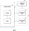
- Gas detection apparatus 10 is an example embodiment that may be embodied by or associated with any of a variety of computing devices that include or are otherwise associated with a device configured for providing advanced sensory features, which may include a sensor assembly 24.
- gas detection apparatus 10 may be embodied as a plurality of oxygen concentration sensors configured for detecting the concentration of oxygen within a gaseous fluid (e.g., air).
- the oxygen concentration sensors may be an electrochemical oxygen pump configured to monitor oxygen concentration.
- one or more of the oxygen concentration sensors may be a fuel-cell liquid electrolyte electrochemical sensors.
- the electrochemical oxygen pump may employ acid electrolytes and gas diffusion structures for the sensing, counter, and reference electrodes linked to a conventional potentiostatic control circuit.
- gas phase diffusion barriers may be employed.
- Various oxygen sensors may be used in embodiments of the present disclosure, such as a liquid electrolyte electrochemical (e.g., Consumable anode (battery) or fuel cell pump), High Temperature Solid electrolyte electrochemical (e.g., Zirconia or other oxygen ion conductor), and/or Fluorescence Quenching (e.g., ruthenium based dye). While the sensors discussed herein are referred to as oxygen concentration sensors, the sensing devices discussed herein may take the form of partial pressure sensors.
- the gas detection apparatus 10 may include, be associated with, or may otherwise be in communication with a communication interface 26, processor 14, a memory device 16, and a sensor assembly 24.
- the processor 14 (and/or co-processors or any other processing circuitry assisting or otherwise associated with the processor) may be in communication with the memory device 16 (e.g., a non-transitory memory comprising one or more volatile and/or non-volatile memories).
- the memory device may be configured to store information, data, content, applications, instructions, or the like for enabling the gas detection apparatus to carry out various functions in accordance with an example embodiment of the present disclosure.
- the processor 14 may be embodied in a number of different ways.
- the processor 14 may be embodied as one or more of various hardware processing means such as a coprocessor, a microprocessor, a controller, a digital signal processor (DSP), a processing element with or without an accompanying DSP, or various other processing circuitry including integrated circuits such as, for example, an ASIC (application specific integrated circuit), an FPGA (field programmable gate array), a microcontroller unit (MCU), a hardware accelerator, a special-purpose computer chip, or the like.
- the processor may include one or more processing cores configured to perform independently.
- a multi-core processor may enable multiprocessing within a single physical package.
- the processor may include one or more processors configured in tandem via the bus to enable independent execution of instructions, pipelining and/or multithreading.
- the processor 14 may be configured to execute instructions stored in the memory device 16 or otherwise accessible to the processor.
- the processor may be configured to execute hard coded functionality.
- the processor may represent an entity (for example, physically embodied in circuitry) capable of performing operations according to an embodiment of the present disclosure while configured accordingly.
- the processor when the processor is embodied as an ASIC, FPGA or the like, the processor may be specifically configured hardware for conducting the operations described herein.
- the processor when the processor is embodied as an executor of software instructions, the instructions may specifically configure the processor to perform the algorithms and/or operations described herein when the instructions are executed.
- the processor may be a processor of a specific device (for example, the computing device) configured to employ an embodiment of the present disclosure by further configuration of the processor by instructions for performing the algorithms and/or operations described herein.
- the processor may include, among other things, a clock, an arithmetic logic unit (ALU) and logic gates configured to support operation of the processor.
- ALU arithmetic logic unit
- the gas detection apparatus 10 of an example embodiment may also optionally include a communication interface 26 that may be any means such as a device or circuitry embodied in either hardware or a combination of hardware and software that is configured to receive and/or transmit data from/to other electronic devices in communication with the gas detection apparatus, such as by near field communication (NFC) or other proximity-based techniques.
- the communication interface may be configured to communicate via cellular or other wireless protocols including Global System for Mobile Communications (GSM), such as but not limited to Long Term Evolution (LTE).
- GSM Global System for Mobile Communications
- LTE Long Term Evolution
- the communication interface may include, for example, an antenna (or multiple antennas) and supporting hardware and/or software for enabling communications with a wireless communication network.
- the communication interface may include the circuitry for interacting with the antenna(s) to cause transmission of signals via the antenna(s) or to handle receipt of signals received via the antenna(s).
- the gas detection apparatus 10 may include a sensor assembly 24, comprising a primary sensing device 20 and a reference sensing device 22.
- the primary sensing device 20 and the reference sensing device 22 may each be a sensor capable of determining a concentration of one or more gases within a given area.
- the primary sensing device 20 and the reference sensing device 22 may each be a sensor capable of determining a concentration of oxygen in the given area.
- the primary sensing device 20 and the reference sensing device 22 may be similar sensors (e.g., each may be a electrochemical oxygen pump). Alternatively or additionally, the primary sensing device 20 and the reference sensing device 22 may be different types of oxygen sensors.
- the gas detection apparatus 10 may be configured to normalize the oxygen level readings of each sensing device in order to properly compare the oxygen levels.
- the position of the sensing devices may be based on the expected flow path of a leak (e.g., dynamic fluid path).
- the oxygen concentration levels of a given area may change due to various environmental changes, as well as any gases introduced into the area, such as refrigerant due to a refrigerant leak.
- the primary sensing device 20 may be located in a region close to the likely source of a leak, taking due account of the fact that refrigerant gases (e.g., A2L refrigerant) are much heavier than air and will therefore tend to sink.
- refrigerant gases e.g., A2L refrigerant
- the density of air at 20 degrees Celsius may be approximately 1.2 kilograms per cubic meter, while the density of refrigerants may be substantially more dense at the same temperature (e.g., saturated R32 vapor may have a density of 40.8 kilograms per cubic meter and R410 may have a density of 57.6 kilograms per cubic meter).
- the reference sensing device 22 may be mounted in a location where the reference sensing device will experience lower concentrations of any leaking refrigerant and hence smaller and slower oxygen depletion (if any). Slower long term background changes should still be well compensated under this arrangement, although there is some concern that if the target area is close to components whose temperature fluctuates rapidly, the efficiency of the compensation could be compromised.
- the primary sensing device 20 and the reference sensing device 22 may be configured (e.g., through sensor placement and/or the use of target gas filtering) to have different oxygen concentration level readings in an instance in which a gas leak (e.g., refrigerant leak) is present. Additionally, the primary sensing device 20 and the reference sensing device 22 may be configured to have similar oxygen concentration level readings in an instance in which no gas leak is occurring (e.g., the sensing devices may be subjected to similar environmental conditions, such that any changes in the environmental conditions may cause corresponding changes in both sensing devices).
- a gas leak e.g., refrigerant leak
- the reference sensing device 22 may be used to compensate for changes in temperature, pressure, humidity etc. Various embodiments may also use additional external compensating devices for one or more environmental condition. In various embodiments, the output of the primary sensing device 20 may be corrected based on the environmental conditions observed.
- FIG. 2 illustrates an example refrigeration unit 100 in accordance with various embodiments of the present disclosure.
- the refrigeration unit 100 may include one or more closed-loop gas (e.g., refrigerant) coils 110 and a gas detection apparatus 10 (e.g., a sensor assembly 24 and a processing circuitry 12).
- a gas detection apparatus 10 e.g., a sensor assembly 24 and a processing circuitry 12.
- at least a portion of the gas detection apparatus 10 may be disposed in proximity to the given closed-loop gas coil 110 within the refrigeration unit 100.
- the sensor assembly 24 shown in FIG. 1
- the processing circuitry 12 may be disposed elsewhere.
- the gas detection apparatus 10 may be placed in sufficient proximity, such that a leakage of gas (e.g., refrigerant) may result in a change of the oxygen concentration.
- gas detection apparatus 10 may be disposed at a location proximate to an area of the closed-loop gas coils 110 in which leakages occur more than other locations. For example, gas leaks may occur more often at connection between different tubing.
- the gas detection apparatus 10 may be disposed with the refrigeration unit or the like, such that any gas leak may reach the gas detection apparatus 10.
- FIG. 3 is an example configuration of the gas detection apparatus 10 in accordance with an example embodiment.
- the primary sensing device 20 and the reference sensing device 22 may be disposed within the same housing 30.
- the gas detection apparatus 10 may be oriented such that the coil surface 300 is proximate to the coil 110 and a gas (e.g., refrigerant) leakage 215 in an instance such a leakage occurs.
- the primary sensing device 20 may be disposed at a first position and the reference sensing device 22 may be disposed at a second position.
- the first position (e.g., the location of the primary sensing device 20 may be proximate to a potential leak 215 and the second position (e.g., the location of the reference sensing device 22) may be distant to a potential leak.
- the first position may be less than 1 meter from the potential leak 215. In some embodiments, the first position may be less than .75 meters from the potential leak 215. In some embodiments, the first position may be less than .5 meters from the potential leak 215.
- the first position may be less than .25 meters from the potential leak 215.
- the second position may be greater than the first position, but less than 1 meter from the potential leak 215.
- the second position may be greater than the first position, but less than .75 meters from the potential leak 215.
- the second position may be greater than the first position, but less than .5 meters from the potential leak 215.
- the second position may be greater than the first position, but less than .25 meters from the potential leak 215.
- at least one of the first position or the second position may be greater than 1 meter from the potential leak 215, in an instance in which the first position and/or second position is still within the flow path of the leakage gas.
- the first position may be closer to the coil surface 300 than the second position and therefore any gas leakage 215 may reach the primary sensing device 20 before the reference sensing device 22.
- the first oxygen concentration level reading captured by the primary sensing device 20 may be altered due to the gas leak (e.g., the oxygen concentration may decrease) before the second oxygen concentration level reading captured by the reference sensing device 22 is altered.
- the first oxygen concentration level reading may decrease more quickly than the second oxygen concentration level reading.
- the reference sensing device 22 may also be oriented differently from the primary sensing device 20, such that the gas flowing from the potential leak does not access the reference sensing device 22 as easily as the primary sensing device 20 (e.g., as the arrows in FIG. 3 shown, the target gas may flow directly into the primary sensing device 20, but may have to travel around the processing circuitry 12 to access the reference sensing device 22). As such, the temporal effect of the gas flow may be more definitively shown by the outputs of each sensing device.
- the location of the first position and the second position may be based on the expected flow path of a potential leak.
- a potential leak may be defined as an area susceptible to leakage. For instance in a refrigeration unit, the potential leakage locations may include braised joints, connections between tubing, areas under mechanical and/or thermal stress, and/or the like. In various embodiments, the potential leakage location may be determined via testing of specific applications.
- the reference sensing device 22 may be disposed outside of the housing 30, such that the reference sensing device 22 may not receive any of the target gas during a leakage instance. In such an instance, the reference sensing device 22 may be located in an area with similar environmental conditions to the position of the primary sensing device 20. While FIG. 3 shows only a single primary sensing device 20 and a single reference sensing device 22, various embodiments may use more than two sensing devices disposed at different locations. For example, multiple reference sensing devices 22 may be positioned at various positions from the potential leak and as such may experience changes to the reading at different times during a leakage instance.
- the processing circuitry 12 may be disposed within the gas detection apparatus 10 (e.g., in the same housing 30 as the primary sensing device 20 and the reference sensing device 22). As shown, the primary sensing device 20 and/or the reference sensing device 22 may be connected to the processing circuitry 12 via pins on the sensing devices configured to engage with sockets on the processing circuitry 12. Various embodiments may employ different connection methods, such as pads configured on the sensing devices and pogo pins on the processing circuitry 12. Various embodiments discussed herein may have any number of different standard electrical interconnects between the sensing devices and the processing circuitry 12.
- the primary sensing device 20 and/or the reference sensing device 22 may be equipped with short range communication capabilities to allow the sensing devices to communicate with the processing circuitry 12 remotely.
- the processing circuitry 12 may be configured to receive oxygen concentration level readings from the primary sensing device 20 and the reference sensing device 22.
- the processing circuitry 12 may store one or more of the oxygen concentration level readings, such that the oxygen concentration level readings may be monitored over time (e.g., the first oxygen concentration level readings and the second oxygen concentration level readings may diverge over time due to a leak).
- time sequence data may be used to determine leak instances.
- the monitoring may be continuous. Alternatively, the monitoring may occur at intervals based on the gas leakage application (e.g., some gas leaks may not be as dangerous and intermittent monitoring may be cost-saving).
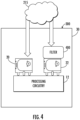
- FIG. 4 is another example configuration of the gas detection apparatus 10 in accordance with an example embodiment.
- the primary sensing device 20 and the reference sensing device 22 may be disposed within the same housing 30.
- the primary sensing device 20 and the reference sensing device 22 may be disposed at a first position and a second position approximately the same distance from the coil surface 300 and as such, the primary sensing device 20 and the reference sensing device 22 may receive any gas (e.g., refrigerant) from a leak at approximately the same time.
- any gas e.g., refrigerant
- the reference sensing device 22 may be equipped with a filter 400 configured to remove one or more target gases (e.g., refrigerants) from the gas entering the reference sensing device 22.
- the filter 400 may be configured to absorb one or more target gases (e.g., refrigerant gases) that pass therein.
- the filter 400 may be an absorber.
- the filter 400 may be positioned between the closed-loop gas coil 110 and the reference sensing device 22, such that any gas combination that reaches the reference sensing device has passed through the filter 400 (e.g., removing some or all of the refrigerant gas).
- the filter 400 may be activated carbons of various types. In some such embodiments, the activated carbons may be impregnated with other chemicals depending on the species to be absorbed. In some embodiments, molecular sieves, zeolites, and/or other well know filter families may be used.
- the target gas may dictate the design of the filter 400 (e.g., Sofnocarb powder may be used in an instance in which Butane is the target gas).
- the filter 400 may be designed to permanently absorb the target gas or simply to slow down its passage to the reference sensing device, such that a temporal difference arises in the response compared to the primary sensing device.
- the primary sensing device 20 and the reference sensing device 22 may be a single sensor with a plurality of gas feeds.
- the single sensor may have a primary sensing device gas feed without a filter 400 and a reference sensing device gas feed that may have a filter 400.
- the sensing device may have a mechanical switch configured to alternate access to a sensing electrode from the primary sensing device gas feed to the reference sensing device gas feed during operation.
- various pumping devices may be used to move the gas from the gas feeds to the sensing electrode.
- the mechanical switch may alternate between the primary sensing device gas feed and the reference sensing device gas feed and the differences between the first oxygen level reading from the primary sensing device gas feed and the second oxygen level reading may be compared as discussed herein with a two sensing device system.
- the first oxygen concentration level reading of the primary sensing device 20 may begin to decrease, while the second oxygen concentration level reading of the reference sensing device 22 remains approximately constant (or at least decreases more slowly).
- the filter 400 may be become overwhelmed (e.g., fully saturated) at a specific point, such that the second oxygen concentration level reading of the reference sensing device 22 may begin to decrease in line with a sensing device without a filter.
- the time lag between the decrease of the first oxygen concentration level and the second oxygen concentration level may indicate that a gas leakage is occurring.
- various other information may be determined via the individual outputs of the sensing devices.
- the processing circuitry 12 may be disposed within the gas detection apparatus 10 (e.g., in the same housing 30 as the primary sensing device 20 and the reference sensing device 22). As shown, the primary sensing device 20 and/or the reference sensing device 22 may be connected to the processing circuitry 12 via pins on the sensing devices configured to engage with sockets on the processing circuitry 12. Various embodiments may employ different connection methods, such as pads configured on the sensing devices and pogo pins on the processing circuitry 12. Various embodiments discussed herein may have any number of different standard electrical interconnects between the sensing devices and the processing circuitry 12.
- the primary sensing device 20 and/or the reference sensing device 22 may be equipped with short range communication capabilities to allow the sensing devices to communicate with the processing circuitry 12 remotely.
- the processing circuitry 12 may be configured to receive oxygen concentration level readings from the primary sensing device 20 and the reference sensing device 22.
- the processing circuitry 12 may store one or more of the oxygen concentration level readings, such that the oxygen concentration level readings may be monitored over time (e.g., the first oxygen concentration level readings and the second oxygen concentration level readings may diverge over time due to a leak).
- the monitoring may be continuous. Alternatively, the monitoring may occur at intervals based on the gas leakage application (e.g., some gas leaks may not be as dangerous and intermittent monitoring may be cost-saving).
- an example embodiment of the present disclosure includes a flow diagram for the processing circuitry 12, the processor 14, the sensor assembly 24, or the like, to monitor and detect a gas (e.g., refrigerant) leak.
- a gas e.g., refrigerant
- various embodiments of the gas detection apparatus may include at least one processor 12, various embodiments of the gas detection apparatus may be analog systems, such that the primary sensing device 20 and the reference sensing device 22 may be in communication with a differential amplifier and/or ratio amplifier and use a comparator to determine an instance in which a leakage is occurring. As such, the operations of FIG. 5 may be carried out by an analog system.
- the gas detection apparatus 10 may include means for receiving a first oxygen concentration level reading of a given area.
- the first oxygen concentration level reading may be captured by the primary sensing device 20.
- the first oxygen concentration level reading may be affected by the environmental conditions, such as temperature or the like. Additionally, in some embodiments, the first oxygen concentration level reading may be affected by the introduction of new gases (e.g., such as a gas leak causing the oxygen concentration to decrease).
- the gas detection apparatus 10 may include means for receiving a second oxygen concentration level reading of the given area.
- the first oxygen concentration level reading may be captured by the reference sensing device 22.
- the reference sensing device 22 may be positioned in similar environmental conditions, such that the effects of the environmental conditions on the second oxygen concentration level reading may be similar or the same to the effects of the environmental conditions on the first oxygen concentration level reading.
- the reference sensing device 22 may be configured such that a gas leak 215 may have a different effect on the second oxygen concentration level reading from the reference sensing device 22 than on the first oxygen concentration level reading from the primary sensing device 20.
- the second oxygen concentration level reading may begin to decrease a time after the first oxygen concentration level reading begins to decrease, as the gas (e.g., refrigerant) may take longer to reach the reference sensing device 22.
- the second oxygen concentration level may not decrease, at least for an amount of time until the filter is saturated, due to a gas leak, while the first oxygen concentration level may decrease due to said gas leak.
- the gas detection apparatus 10 may include means for comparing the first oxygen concentration level reading and the second oxygen concentration level reading.
- the difference in the first oxygen concentration level reading and the second oxygen concentration level reading may correlate to the amount of gas leakage.
- the comparison may be at a given time (e.g., at an instance in which the primary sensing device 20 has a lower oxygen concentration level reading than the reference sensing device 22).
- the first oxygen concentration level reading and the second oxygen concentration level reading may be monitored over time, such that changes in the first oxygen concentration level reading and the second oxygen concentration level reading may indicate that a gas leak is occurring.
- the primary sensing device 20 and the secondary sensing device 22 may measure an output current, that is converted to a voltage, the individual output voltages may be amplified to eliminate any noise. As such, the voltages may be compared using either a differential or a ratio. In such an analog embodiment, a comparator may be used to determine a leak has occurred.
- the gas detection apparatus 10 may include means for causing a transmission of a signal that a gas (e.g., refrigerant) leak is occurring in an instance in which the first oxygen concentration level reading and the second oxygen concentration level reading have a difference greater than a threshold difference.
- a gas e.g., refrigerant
- the determination that a gas leak may be occurring may be based on the comparison of the first oxygen concentration level reading and the second oxygen concentration level reading.
- the amount of target gas (e.g., refrigerant) allowable to leak may be based on the flammability of said gas.
- the threshold difference may be lower than the flammability level of the target gas.
- the threshold difference may be 1%.
- a 1% change in the oxygen concentration e.g., from 20.9% oxygen concentration to 20.7% oxygen concentration
- 1% leakage gas e.g., refrigerant
- the difference between the first oxygen concentration level reading and the second oxygen concentration level reading may correlate to the change in oxygen concentration (e.g., the primary sensing device 20 and the reference sensing device 22 may be configured such that only an introduction of the target gas (e.g., a gas leak) may cause the first oxygen concentration level reading and the second oxygen concentration level reading to differ substantially).
- the threshold difference may be between approximately 5% and 10% of the volume of oxygen concentration level.
- FIG. 6 is a graph showing the similar oxygen concentration readings of two sensors, such as the oxygen sensor used in various embodiments herein, during changes to the oxygen level in the air.
- the two sensors which are being exposed to the same air, shown almost identical readings and therefore can be relied upon to shown substantial changes in the oxygen level.
- the S2/S 1 line shown is the ratio of the Sensor 2 reading and the Sensor 1 reading. As shown, the ratio is approximately 1 and therefore any change to one of the sensor readings (e.g., in an instance a gas leakage occur and the primary sensing device 20 experiences a decrease in oxygen before the reference sensing device 22), may be represented by a change of the ratio from approximately 1.
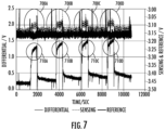
- FIG. 7 illustrates the output of a gas detection apparatus, similar to the gas detection apparatus shown in FIG. 4 , wherein the reference sensing device 22 is equipped with a target gas filter 400.
- the target gas is butane.
- the target gas is intermittently being introduced to the gas detection apparatus and each time the target gas is introduced, the primary sensing device 20 experiences a spike above the nominal voltage (e.g., spikes 700A-700D), while the voltage of the reference sensing device 22 remains approximately constant due to the filter absorbing the butane.
- a differential is used to show an instance in which a leak is occurring and are shown as spikes 710A-710D.
- Refrigeration units include closed-loop refrigerant coils that contain flammable refrigerants.
- A2L refrigerants are being used more often in such refrigeration units due to a lower global warming potential (GWP) and therefore regulations have been put into place in various countries to monitor leakage to avoid dangerous conditions during use.
- GWP global warming potential
- A2L refrigerants have generally low toxicity and only mild flammability, large leaks can still cause dangerous situations. Therefore, monitoring and detection of such leaks are necessary for refrigerant units.
- Various embodiments of the present disclosure allow for a simple, yet effective leakage monitoring system.
- Figure 5 is a flowchart of various aspects of a gas detection apparatus 10 and method according to example embodiments. It will be understood that each block of the flowchart, and combinations of blocks in the flowchart, may be implemented by various means, such as hardware, firmware, processor, circuitry, and/or other devices associated with execution of software including one or more computer program instructions. For example, one or more of the procedures described above may be embodied by computer program instructions stored and executable via the memory of the gas detection apparatus.
- Blocks of the flowchart support combinations of means for performing the specified functions and combinations of operations for performing the specified functions. It will also be understood that one or more blocks of the flowchart, and combinations of blocks in the flowchart, can be implemented by special purpose hardware-based computer systems which perform the specified functions, or combinations of special purpose hardware and computer instructions.
- certain ones of the operations above may be modified or further amplified. Furthermore, in some embodiments, additional optional operations may be included. Modifications, additions, or amplifications to the operations above may be performed in any order and in any combination.
Landscapes
- Physics & Mathematics (AREA)
- Engineering & Computer Science (AREA)
- General Physics & Mathematics (AREA)
- Mechanical Engineering (AREA)
- General Engineering & Computer Science (AREA)
- Thermal Sciences (AREA)
- Chemical & Material Sciences (AREA)
- Combustion & Propulsion (AREA)
- Investigating Or Analyzing Materials By The Use Of Electric Means (AREA)
- Emergency Alarm Devices (AREA)
- Examining Or Testing Airtightness (AREA)
Claims (11)
- Procédé de détermination d'une fuite de gaz par un ensemble capteur (24), l'ensemble capteur (24) comprenant un dispositif détecteur principal (20) et un dispositif détecteur de référence (22) et le procédé comprenant :la réception (500), via le dispositif détecteur principal (20), d'un premier relevé du niveau de concentration en oxygène d'une zone donnée, le dispositif détecteur principal (20) étant positionné en une première position et le dispositif détecteur de référence (22) étant positionné en une seconde position ;la réception (510), via le dispositif détecteur de référence (22), d'un second relevé du niveau de concentration en oxygène de la zone donnée, le dispositif détecteur de référence (22) comprenant un filtre à gaz (400) conçu pour empêcher un ou plusieurs gaz cibles d'atteindre le dispositif détecteur de référence (22) ;la comparaison (520) du premier relevé de niveau de concentration en oxygène au second relevé de niveau de concentration en oxygène ; etd'après la comparaison, si le premier relevé de niveau de concentration en oxygène et le second relevé de niveau de concentration en oxygène diffèrent de plus d'une différence seuil, le déclenchement (530) de la transmission d'un signal indiquant l'occurrence d'une fuite de gaz,caractérisé en ce que les deux dispositifs détecteurs (20, 22) sont disposés dans le même boîtier d'ensemble capteur (30) et en ce que la première position est proche d'une source potentielle de fuites (215) et en ce que la seconde position est éloignée de la source potentielle de fuites (215).
- Procédé selon la revendication 1, dans lequel l'ensemble capteur (24) est disposé dans une unité réfrigérante (100).
- Procédé selon la revendication 1 ou 2, comprenant en outre la réception d'une ou plusieurs variables environnementales et la correction du premier relevé de niveau de concentration en oxygène et du second relevé de niveau de concentration en oxygène d'après les variables environnementales.
- Procédé selon la revendication 1, dans lequel le dispositif détecteur principal (20) et le dispositif détecteur de référence (22) sont connectés à une circuiterie de traitement (12) à l'intérieur du boîtier d'ensemble capteur (30) et dans lequel le dispositif détecteur de référence (22) est orienté différemment du dispositif détecteur principal (20).
- Appareil détecteur de gaz (10) selon la revendication 4, dans lequel le dispositif détecteur principal (20) et le dispositif détecteur de référence (22) sont positionnés sur des côtés opposés de la circuiterie de traitement (12), le dispositif détecteur principal (20) faisant face à la source potentielle de fuites (215).
- Appareil détecteur de gaz (10) permettant de déterminer une composition d'un ou de plusieurs gaz, comprenant un ensemble capteur (24) comprenant un dispositif détecteur principal (20) et un dispositif détecteur de référence (22), l'appareil détecteur de gaz (10) étant conçu :pour recevoir, via le dispositif détecteur principal (20), un premier relevé du niveau de concentration en oxygène d'une zone donnée, le dispositif détecteur principal (20) étant positionné en une première position et le dispositif détecteur de référence (22) étant positionné en une seconde position ;pour recevoir, via le dispositif détecteur de référence (22), un second relevé du niveau de concentration en oxygène de la zone donnée, le dispositif détecteur de référence (22) comprenant un filtre à gaz (400) conçu pour empêcher un ou plusieurs gaz cibles d'atteindre le dispositif détecteur de référence (22) ;pour comparer le premier relevé de niveau de concentration en oxygène au second relevé de niveau de concentration en oxygène ; etd'après la comparaison, si le premier relevé de niveau de concentration en oxygène et le second relevé de niveau de concentration en oxygène diffèrent de plus d'une différence seuil, pour déclencher une transmission indiquant l'occurrence d'une fuite de gaz,caractérisé en ce que les deux dispositifs détecteurs (20, 22) sont disposés dans le même boîtier d'ensemble capteur (30) et en ce que la première position est proche d'une source potentielle de fuites (215) et en ce que la seconde position est éloignée de la source potentielle de fuites (215).
- Appareil détecteur de gaz (10) selon la revendication 6, dans lequel l'ensemble capteur (24) est disposé dans une unité réfrigérante (100).
- Appareil détecteur de gaz (10) selon la revendication 6 ou 7, dans lequel la différence seuil est basée sur entre 5 % et 10 % du volume du niveau de concentration en oxygène.
- Appareil détecteur de gaz (10) selon l'une quelconque des revendications 6 à 8, l'appareil détecteur de gaz (10) étant en outre conçu pour recevoir une ou plusieurs variables environnementales et pour corriger le premier relevé de niveau de concentration en oxygène et le second relevé de niveau de concentration en oxygène d'après les variables environnementales.
- Appareil détecteur de gaz (10) selon la revendication 6, dans lequel le dispositif détecteur principal (20) et le dispositif détecteur de référence (22) sont connectés à une circuiterie de traitement (12) à l'intérieur du boîtier d'ensemble capteur (30) et dans lequel le dispositif détecteur de référence (22) est orienté différemment du dispositif détecteur principal (20).
- Appareil détecteur de gaz (10) selon la revendication 10, dans lequel le dispositif détecteur principal (20) et le dispositif détecteur de référence (22) sont positionnés sur des côtés opposés de la circuiterie de traitement (12), le dispositif détecteur principal (20) faisant face à la source potentielle de fuites (215).
Applications Claiming Priority (1)
| Application Number | Priority Date | Filing Date | Title |
|---|---|---|---|
| US16/818,687 US11635339B2 (en) | 2020-03-13 | 2020-03-13 | Gas leakage monitoring system |
Publications (2)
| Publication Number | Publication Date |
|---|---|
| EP3879202A1 EP3879202A1 (fr) | 2021-09-15 |
| EP3879202B1 true EP3879202B1 (fr) | 2023-05-03 |
Family
ID=74844702
Family Applications (1)
| Application Number | Title | Priority Date | Filing Date |
|---|---|---|---|
| EP21159736.4A Active EP3879202B1 (fr) | 2020-03-13 | 2021-02-26 | Système de surveillance de fuite de gaz |
Country Status (3)
| Country | Link |
|---|---|
| US (1) | US11635339B2 (fr) |
| EP (1) | EP3879202B1 (fr) |
| CN (1) | CN113390562A (fr) |
Families Citing this family (4)
| Publication number | Priority date | Publication date | Assignee | Title |
|---|---|---|---|---|
| US11231198B2 (en) | 2019-09-05 | 2022-01-25 | Trane International Inc. | Systems and methods for refrigerant leak detection in a climate control system |
| IT202000015214A1 (it) * | 2020-06-24 | 2021-12-24 | Co Ref S R L | Apparecchio di monitoraggio per rilevare perdite di un fluido refrigerante da una valvola di sicurezza di un impianto di refrigerazione industriale |
| US12487008B2 (en) | 2022-01-14 | 2025-12-02 | Trane International Inc. | Method of commissioning an HVAC system |
| US12117191B2 (en) | 2022-06-24 | 2024-10-15 | Trane International Inc. | Climate control system with improved leak detector |
Family Cites Families (16)
| Publication number | Priority date | Publication date | Assignee | Title |
|---|---|---|---|---|
| JPS5853752A (ja) | 1981-09-25 | 1983-03-30 | Toshiba Corp | ハロゲン化炭化水素ガス漏洩検知素子 |
| US4890459A (en) | 1988-12-08 | 1990-01-02 | Thermo King Corporation | Monitor for refrigeration system |
| US5879631A (en) * | 1996-04-30 | 1999-03-09 | Manning System, Inc. | Gas detection system and method |
| US6840086B2 (en) | 2003-03-06 | 2005-01-11 | Cincinnati Test Systems, Inc. | Method and apparatus for detecting leaks |
| US20060257288A1 (en) * | 2005-05-03 | 2006-11-16 | Teledyne Technologies Incorporated | Hydrogen sulfide tolerant oxygen gas sensing device |
| GB0722574D0 (en) * | 2007-11-16 | 2007-12-27 | Life Safety Distribution Ag | Method of measuring a target gas at low concentration |
| JP5757837B2 (ja) | 2011-10-11 | 2015-08-05 | ジーエルサイエンス株式会社 | ガスリ−クディテクタ− |
| CN202853851U (zh) * | 2012-04-25 | 2013-04-03 | 石家庄信息工程职业学院 | 气体泄漏检测装置 |
| EP3159633B1 (fr) * | 2014-06-19 | 2019-08-28 | Mitsubishi Electric Corporation | Unité intérieure pour dispositif de climatisation, et dispositif de climatisation comprenant ladite unité intérieure |
| US20170254737A1 (en) * | 2014-08-28 | 2017-09-07 | Koninklijke Philips N.V. | Sensor system and sensing method |
| KR101631445B1 (ko) * | 2014-12-02 | 2016-06-17 | 엘지전자 주식회사 | 공기조화기 및 공기조화기용 센서유닛 |
| US9528448B2 (en) * | 2015-02-19 | 2016-12-27 | Ford Global Technologies, Llc | Methods and system for fuel ethanol content estimation and engine control |
| CN106645295A (zh) | 2016-12-27 | 2017-05-10 | 北京七星华创电子股份有限公司 | 气体泄漏探测装置及气体泄漏位置的探测方法 |
| JP7042222B2 (ja) * | 2017-02-03 | 2022-03-25 | ネクセリス イノベーション ホールディングス,エルエルシー | ガス検体について監視するシステム及び方法 |
| EP3779324B1 (fr) | 2018-04-09 | 2023-03-29 | Mitsubishi Electric Corporation | Climatiseur |
| CN208654116U (zh) * | 2018-07-03 | 2019-03-26 | 深圳智人环保科技有限公司 | 一种气体检测系统 |
-
2020
- 2020-03-13 US US16/818,687 patent/US11635339B2/en active Active
-
2021
- 2021-02-23 CN CN202110202790.1A patent/CN113390562A/zh active Pending
- 2021-02-26 EP EP21159736.4A patent/EP3879202B1/fr active Active
Also Published As
| Publication number | Publication date |
|---|---|
| US11635339B2 (en) | 2023-04-25 |
| CN113390562A (zh) | 2021-09-14 |
| US20210285840A1 (en) | 2021-09-16 |
| EP3879202A1 (fr) | 2021-09-15 |
Similar Documents
| Publication | Publication Date | Title |
|---|---|---|
| EP3879202B1 (fr) | Système de surveillance de fuite de gaz | |
| US12078368B2 (en) | Apparatuses, systems, and methods for gas leak detection | |
| EP3818352B1 (fr) | Procédé et système de détection de gaz inflammable | |
| US20210207830A1 (en) | Gas monitoring apparatus and method | |
| CN115917227A (zh) | 制冷泄漏检测 | |
| JP2022050506A (ja) | 空調システム、及び空調システムにおけるリーク検出法 | |
| US11604156B2 (en) | Method and system for multi-sensor gas detection | |
| CN103884480B (zh) | 冷媒泄漏检测方法、冷媒泄漏检测系统和空调器 | |
| KR102933499B1 (ko) | 냉각 시스템 누출 검출 | |
| WO2021050886A1 (fr) | Agencement de double capteur de température pour détecter une fuite de fluide frigorigène | |
| US20210396412A1 (en) | Air-conditioning apparatus | |
| CN110296499A (zh) | 一种电子膨胀阀异常原因判断方法、装置及空调器 | |
| US9146048B2 (en) | Chemical state monitor for refrigeration system | |
| US11781767B2 (en) | Apparatuses, systems, and methods for gas leak detection | |
| JP6755263B2 (ja) | 冷媒分析装置及び冷媒分析装置を利用して冷媒ガス内の不純物を検出する方法 | |
| US11525754B2 (en) | Leak detection system and method | |
| Dutta et al. | Advanced detection of refrigerant leakage using pressure sensor information in variable refrigerant flow systems | |
| CN114446000B (zh) | 自测试管道环境检测器 | |
| RU2239807C2 (ru) | Способ испытания на герметичность и вакуумная система течеискателя, реализующая его | |
| CN115388334B (zh) | 循环管路系统及循环管路控制方法 | |
| EP3120131A1 (fr) | Capteur de corrosion pour échangeurs de chaleur | |
| JP2006064277A (ja) | 空気調和機の制御装置 | |
| BRPI0703028B1 (pt) | Conjunto de sensor elétrico de impedãncia de fase de escoamento de mistura de refrigerante e método de controle de sistema de refrigeração | |
| JP2018084378A (ja) | 冷媒漏洩検知方法及び冷媒漏洩検知手段 |
Legal Events
| Date | Code | Title | Description |
|---|---|---|---|
| PUAI | Public reference made under article 153(3) epc to a published international application that has entered the european phase |
Free format text: ORIGINAL CODE: 0009012 |
|
| STAA | Information on the status of an ep patent application or granted ep patent |
Free format text: STATUS: REQUEST FOR EXAMINATION WAS MADE |
|
| 17P | Request for examination filed |
Effective date: 20210226 |
|
| AK | Designated contracting states |
Kind code of ref document: A1 Designated state(s): AL AT BE BG CH CY CZ DE DK EE ES FI FR GB GR HR HU IE IS IT LI LT LU LV MC MK MT NL NO PL PT RO RS SE SI SK SM TR |
|
| GRAP | Despatch of communication of intention to grant a patent |
Free format text: ORIGINAL CODE: EPIDOSNIGR1 |
|
| STAA | Information on the status of an ep patent application or granted ep patent |
Free format text: STATUS: GRANT OF PATENT IS INTENDED |
|
| INTG | Intention to grant announced |
Effective date: 20221129 |
|
| GRAS | Grant fee paid |
Free format text: ORIGINAL CODE: EPIDOSNIGR3 |
|
| GRAA | (expected) grant |
Free format text: ORIGINAL CODE: 0009210 |
|
| STAA | Information on the status of an ep patent application or granted ep patent |
Free format text: STATUS: THE PATENT HAS BEEN GRANTED |
|
| AK | Designated contracting states |
Kind code of ref document: B1 Designated state(s): AL AT BE BG CH CY CZ DE DK EE ES FI FR GB GR HR HU IE IS IT LI LT LU LV MC MK MT NL NO PL PT RO RS SE SI SK SM TR |
|
| REG | Reference to a national code |
Ref country code: GB Ref legal event code: FG4D |
|
| REG | Reference to a national code |
Ref country code: DE Ref legal event code: R096 Ref document number: 602021002098 Country of ref document: DE |
|
| REG | Reference to a national code |
Ref country code: AT Ref legal event code: REF Ref document number: 1564905 Country of ref document: AT Kind code of ref document: T Effective date: 20230515 Ref country code: CH Ref legal event code: EP |
|
| REG | Reference to a national code |
Ref country code: IE Ref legal event code: FG4D |
|
| REG | Reference to a national code |
Ref country code: LT Ref legal event code: MG9D |
|
| REG | Reference to a national code |
Ref country code: NL Ref legal event code: MP Effective date: 20230503 |
|
| REG | Reference to a national code |
Ref country code: AT Ref legal event code: MK05 Ref document number: 1564905 Country of ref document: AT Kind code of ref document: T Effective date: 20230503 |
|
| PG25 | Lapsed in a contracting state [announced via postgrant information from national office to epo] |
Ref country code: SE Free format text: LAPSE BECAUSE OF FAILURE TO SUBMIT A TRANSLATION OF THE DESCRIPTION OR TO PAY THE FEE WITHIN THE PRESCRIBED TIME-LIMIT Effective date: 20230503 Ref country code: PT Free format text: LAPSE BECAUSE OF FAILURE TO SUBMIT A TRANSLATION OF THE DESCRIPTION OR TO PAY THE FEE WITHIN THE PRESCRIBED TIME-LIMIT Effective date: 20230904 Ref country code: NO Free format text: LAPSE BECAUSE OF FAILURE TO SUBMIT A TRANSLATION OF THE DESCRIPTION OR TO PAY THE FEE WITHIN THE PRESCRIBED TIME-LIMIT Effective date: 20230803 Ref country code: NL Free format text: LAPSE BECAUSE OF FAILURE TO SUBMIT A TRANSLATION OF THE DESCRIPTION OR TO PAY THE FEE WITHIN THE PRESCRIBED TIME-LIMIT Effective date: 20230503 Ref country code: ES Free format text: LAPSE BECAUSE OF FAILURE TO SUBMIT A TRANSLATION OF THE DESCRIPTION OR TO PAY THE FEE WITHIN THE PRESCRIBED TIME-LIMIT Effective date: 20230503 Ref country code: AT Free format text: LAPSE BECAUSE OF FAILURE TO SUBMIT A TRANSLATION OF THE DESCRIPTION OR TO PAY THE FEE WITHIN THE PRESCRIBED TIME-LIMIT Effective date: 20230503 |
|
| PG25 | Lapsed in a contracting state [announced via postgrant information from national office to epo] |
Ref country code: RS Free format text: LAPSE BECAUSE OF FAILURE TO SUBMIT A TRANSLATION OF THE DESCRIPTION OR TO PAY THE FEE WITHIN THE PRESCRIBED TIME-LIMIT Effective date: 20230503 Ref country code: PL Free format text: LAPSE BECAUSE OF FAILURE TO SUBMIT A TRANSLATION OF THE DESCRIPTION OR TO PAY THE FEE WITHIN THE PRESCRIBED TIME-LIMIT Effective date: 20230503 Ref country code: LV Free format text: LAPSE BECAUSE OF FAILURE TO SUBMIT A TRANSLATION OF THE DESCRIPTION OR TO PAY THE FEE WITHIN THE PRESCRIBED TIME-LIMIT Effective date: 20230503 Ref country code: LT Free format text: LAPSE BECAUSE OF FAILURE TO SUBMIT A TRANSLATION OF THE DESCRIPTION OR TO PAY THE FEE WITHIN THE PRESCRIBED TIME-LIMIT Effective date: 20230503 Ref country code: IS Free format text: LAPSE BECAUSE OF FAILURE TO SUBMIT A TRANSLATION OF THE DESCRIPTION OR TO PAY THE FEE WITHIN THE PRESCRIBED TIME-LIMIT Effective date: 20230903 Ref country code: HR Free format text: LAPSE BECAUSE OF FAILURE TO SUBMIT A TRANSLATION OF THE DESCRIPTION OR TO PAY THE FEE WITHIN THE PRESCRIBED TIME-LIMIT Effective date: 20230503 Ref country code: GR Free format text: LAPSE BECAUSE OF FAILURE TO SUBMIT A TRANSLATION OF THE DESCRIPTION OR TO PAY THE FEE WITHIN THE PRESCRIBED TIME-LIMIT Effective date: 20230804 |
|
| PG25 | Lapsed in a contracting state [announced via postgrant information from national office to epo] |
Ref country code: FI Free format text: LAPSE BECAUSE OF FAILURE TO SUBMIT A TRANSLATION OF THE DESCRIPTION OR TO PAY THE FEE WITHIN THE PRESCRIBED TIME-LIMIT Effective date: 20230503 |
|
| PG25 | Lapsed in a contracting state [announced via postgrant information from national office to epo] |
Ref country code: SK Free format text: LAPSE BECAUSE OF FAILURE TO SUBMIT A TRANSLATION OF THE DESCRIPTION OR TO PAY THE FEE WITHIN THE PRESCRIBED TIME-LIMIT Effective date: 20230503 |
|
| PG25 | Lapsed in a contracting state [announced via postgrant information from national office to epo] |
Ref country code: SM Free format text: LAPSE BECAUSE OF FAILURE TO SUBMIT A TRANSLATION OF THE DESCRIPTION OR TO PAY THE FEE WITHIN THE PRESCRIBED TIME-LIMIT Effective date: 20230503 Ref country code: SK Free format text: LAPSE BECAUSE OF FAILURE TO SUBMIT A TRANSLATION OF THE DESCRIPTION OR TO PAY THE FEE WITHIN THE PRESCRIBED TIME-LIMIT Effective date: 20230503 Ref country code: RO Free format text: LAPSE BECAUSE OF FAILURE TO SUBMIT A TRANSLATION OF THE DESCRIPTION OR TO PAY THE FEE WITHIN THE PRESCRIBED TIME-LIMIT Effective date: 20230503 Ref country code: EE Free format text: LAPSE BECAUSE OF FAILURE TO SUBMIT A TRANSLATION OF THE DESCRIPTION OR TO PAY THE FEE WITHIN THE PRESCRIBED TIME-LIMIT Effective date: 20230503 Ref country code: DK Free format text: LAPSE BECAUSE OF FAILURE TO SUBMIT A TRANSLATION OF THE DESCRIPTION OR TO PAY THE FEE WITHIN THE PRESCRIBED TIME-LIMIT Effective date: 20230503 Ref country code: CZ Free format text: LAPSE BECAUSE OF FAILURE TO SUBMIT A TRANSLATION OF THE DESCRIPTION OR TO PAY THE FEE WITHIN THE PRESCRIBED TIME-LIMIT Effective date: 20230503 |
|
| REG | Reference to a national code |
Ref country code: DE Ref legal event code: R097 Ref document number: 602021002098 Country of ref document: DE |
|
| PLBE | No opposition filed within time limit |
Free format text: ORIGINAL CODE: 0009261 |
|
| STAA | Information on the status of an ep patent application or granted ep patent |
Free format text: STATUS: NO OPPOSITION FILED WITHIN TIME LIMIT |
|
| 26N | No opposition filed |
Effective date: 20240206 |
|
| PG25 | Lapsed in a contracting state [announced via postgrant information from national office to epo] |
Ref country code: SI Free format text: LAPSE BECAUSE OF FAILURE TO SUBMIT A TRANSLATION OF THE DESCRIPTION OR TO PAY THE FEE WITHIN THE PRESCRIBED TIME-LIMIT Effective date: 20230503 |
|
| PG25 | Lapsed in a contracting state [announced via postgrant information from national office to epo] |
Ref country code: SI Free format text: LAPSE BECAUSE OF FAILURE TO SUBMIT A TRANSLATION OF THE DESCRIPTION OR TO PAY THE FEE WITHIN THE PRESCRIBED TIME-LIMIT Effective date: 20230503 Ref country code: IT Free format text: LAPSE BECAUSE OF FAILURE TO SUBMIT A TRANSLATION OF THE DESCRIPTION OR TO PAY THE FEE WITHIN THE PRESCRIBED TIME-LIMIT Effective date: 20230503 |
|
| PG25 | Lapsed in a contracting state [announced via postgrant information from national office to epo] |
Ref country code: MC Free format text: LAPSE BECAUSE OF FAILURE TO SUBMIT A TRANSLATION OF THE DESCRIPTION OR TO PAY THE FEE WITHIN THE PRESCRIBED TIME-LIMIT Effective date: 20230503 |
|
| REG | Reference to a national code |
Ref country code: CH Ref legal event code: PL |
|
| PG25 | Lapsed in a contracting state [announced via postgrant information from national office to epo] |
Ref country code: LU Free format text: LAPSE BECAUSE OF NON-PAYMENT OF DUE FEES Effective date: 20240226 |
|
| PG25 | Lapsed in a contracting state [announced via postgrant information from national office to epo] |
Ref country code: CH Free format text: LAPSE BECAUSE OF NON-PAYMENT OF DUE FEES Effective date: 20240229 |
|
| PG25 | Lapsed in a contracting state [announced via postgrant information from national office to epo] |
Ref country code: LU Free format text: LAPSE BECAUSE OF NON-PAYMENT OF DUE FEES Effective date: 20240226 Ref country code: CH Free format text: LAPSE BECAUSE OF NON-PAYMENT OF DUE FEES Effective date: 20240229 |
|
| PG25 | Lapsed in a contracting state [announced via postgrant information from national office to epo] |
Ref country code: BG Free format text: LAPSE BECAUSE OF FAILURE TO SUBMIT A TRANSLATION OF THE DESCRIPTION OR TO PAY THE FEE WITHIN THE PRESCRIBED TIME-LIMIT Effective date: 20230503 |
|
| PG25 | Lapsed in a contracting state [announced via postgrant information from national office to epo] |
Ref country code: BG Free format text: LAPSE BECAUSE OF FAILURE TO SUBMIT A TRANSLATION OF THE DESCRIPTION OR TO PAY THE FEE WITHIN THE PRESCRIBED TIME-LIMIT Effective date: 20230503 |
|
| REG | Reference to a national code |
Ref country code: BE Ref legal event code: MM Effective date: 20240229 |
|
| PG25 | Lapsed in a contracting state [announced via postgrant information from national office to epo] |
Ref country code: BE Free format text: LAPSE BECAUSE OF NON-PAYMENT OF DUE FEES Effective date: 20240229 |
|
| PG25 | Lapsed in a contracting state [announced via postgrant information from national office to epo] |
Ref country code: IE Free format text: LAPSE BECAUSE OF NON-PAYMENT OF DUE FEES Effective date: 20240226 |
|
| PG25 | Lapsed in a contracting state [announced via postgrant information from national office to epo] |
Ref country code: IE Free format text: LAPSE BECAUSE OF NON-PAYMENT OF DUE FEES Effective date: 20240226 Ref country code: BE Free format text: LAPSE BECAUSE OF NON-PAYMENT OF DUE FEES Effective date: 20240229 |
|
| PG25 | Lapsed in a contracting state [announced via postgrant information from national office to epo] |
Ref country code: CY Free format text: LAPSE BECAUSE OF FAILURE TO SUBMIT A TRANSLATION OF THE DESCRIPTION OR TO PAY THE FEE WITHIN THE PRESCRIBED TIME-LIMIT; INVALID AB INITIO Effective date: 20210226 |
|
| PG25 | Lapsed in a contracting state [announced via postgrant information from national office to epo] |
Ref country code: HU Free format text: LAPSE BECAUSE OF FAILURE TO SUBMIT A TRANSLATION OF THE DESCRIPTION OR TO PAY THE FEE WITHIN THE PRESCRIBED TIME-LIMIT; INVALID AB INITIO Effective date: 20210226 |
|
| PG25 | Lapsed in a contracting state [announced via postgrant information from national office to epo] |
Ref country code: TR Free format text: LAPSE BECAUSE OF FAILURE TO SUBMIT A TRANSLATION OF THE DESCRIPTION OR TO PAY THE FEE WITHIN THE PRESCRIBED TIME-LIMIT Effective date: 20230503 |
|
| PGFP | Annual fee paid to national office [announced via postgrant information from national office to epo] |
Ref country code: GB Payment date: 20260223 Year of fee payment: 6 |
|
| PGFP | Annual fee paid to national office [announced via postgrant information from national office to epo] |
Ref country code: DE Payment date: 20260220 Year of fee payment: 6 |
|
| PGFP | Annual fee paid to national office [announced via postgrant information from national office to epo] |
Ref country code: FR Payment date: 20260224 Year of fee payment: 6 |