EP3819036B1 - Dispositif d'enroulement d'une matière en forme de bande - Google Patents
Dispositif d'enroulement d'une matière en forme de bande Download PDFInfo
- Publication number
- EP3819036B1 EP3819036B1 EP20204083.8A EP20204083A EP3819036B1 EP 3819036 B1 EP3819036 B1 EP 3819036B1 EP 20204083 A EP20204083 A EP 20204083A EP 3819036 B1 EP3819036 B1 EP 3819036B1
- Authority
- EP
- European Patent Office
- Prior art keywords
- feed channel
- plate
- recess
- feed
- channel
- Prior art date
- Legal status (The legal status is an assumption and is not a legal conclusion. Google has not performed a legal analysis and makes no representation as to the accuracy of the status listed.)
- Active
Links
Images






Classifications
-
- B—PERFORMING OPERATIONS; TRANSPORTING
- B21—MECHANICAL METAL-WORKING WITHOUT ESSENTIALLY REMOVING MATERIAL; PUNCHING METAL
- B21C—MANUFACTURE OF METAL SHEETS, WIRE, RODS, TUBES, PROFILES OR LIKE SEMI-MANUFACTURED PRODUCTS OTHERWISE THAN BY ROLLING; AUXILIARY OPERATIONS USED IN CONNECTION WITH METAL-WORKING WITHOUT ESSENTIALLY REMOVING MATERIAL
- B21C47/00—Winding-up, coiling or winding-off metal wire, metal band or other flexible metal material characterised by features relevant to metal processing only
- B21C47/34—Feeding or guiding devices not specially adapted to a particular type of apparatus
-
- B—PERFORMING OPERATIONS; TRANSPORTING
- B21—MECHANICAL METAL-WORKING WITHOUT ESSENTIALLY REMOVING MATERIAL; PUNCHING METAL
- B21C—MANUFACTURE OF METAL SHEETS, WIRE, RODS, TUBES, PROFILES OR LIKE SEMI-MANUFACTURED PRODUCTS OTHERWISE THAN BY ROLLING; AUXILIARY OPERATIONS USED IN CONNECTION WITH METAL-WORKING WITHOUT ESSENTIALLY REMOVING MATERIAL
- B21C47/00—Winding-up, coiling or winding-off metal wire, metal band or other flexible metal material characterised by features relevant to metal processing only
- B21C47/02—Winding-up or coiling
- B21C47/10—Winding-up or coiling by means of a moving guide
- B21C47/12—Winding-up or coiling by means of a moving guide the guide moving parallel to the axis of the coil
-
- B—PERFORMING OPERATIONS; TRANSPORTING
- B21—MECHANICAL METAL-WORKING WITHOUT ESSENTIALLY REMOVING MATERIAL; PUNCHING METAL
- B21C—MANUFACTURE OF METAL SHEETS, WIRE, RODS, TUBES, PROFILES OR LIKE SEMI-MANUFACTURED PRODUCTS OTHERWISE THAN BY ROLLING; AUXILIARY OPERATIONS USED IN CONNECTION WITH METAL-WORKING WITHOUT ESSENTIALLY REMOVING MATERIAL
- B21C47/00—Winding-up, coiling or winding-off metal wire, metal band or other flexible metal material characterised by features relevant to metal processing only
- B21C47/16—Unwinding or uncoiling
- B21C47/18—Unwinding or uncoiling from reels or drums
- B21C47/20—Unwinding or uncoiling from reels or drums the unreeled material moving transversely to the tangent line of the drum, e.g. axially, radially
-
- B—PERFORMING OPERATIONS; TRANSPORTING
- B21—MECHANICAL METAL-WORKING WITHOUT ESSENTIALLY REMOVING MATERIAL; PUNCHING METAL
- B21C—MANUFACTURE OF METAL SHEETS, WIRE, RODS, TUBES, PROFILES OR LIKE SEMI-MANUFACTURED PRODUCTS OTHERWISE THAN BY ROLLING; AUXILIARY OPERATIONS USED IN CONNECTION WITH METAL-WORKING WITHOUT ESSENTIALLY REMOVING MATERIAL
- B21C47/00—Winding-up, coiling or winding-off metal wire, metal band or other flexible metal material characterised by features relevant to metal processing only
- B21C47/34—Feeding or guiding devices not specially adapted to a particular type of apparatus
- B21C47/3408—Feeding or guiding devices not specially adapted to a particular type of apparatus for monitoring the lateral position of the material
- B21C47/3416—Feeding or guiding devices not specially adapted to a particular type of apparatus for monitoring the lateral position of the material with lateral edge contact
Definitions
- the invention relates to a device for winding strip-shaped material onto at least one spool according to the preamble of claim 1.
- strip material is used for many different purposes. For example, in particular for electrical engineering, contact elements are produced in large numbers by stamping the material.
- strip-shaped material e.g.
- a separating material e.g. B. separated by a release paper.
- the strip-shaped material is first processed in the production machine, e.g. punched, and then wound onto a spool using a feed device.
- a movable feed channel is provided, which guides the strip-shaped material to the spool so that it can be wound up.
- the feed channel is moved depending on the degree to which the spool is full, so that the spool can be completely filled. For example, when the material is initially wound onto the spool, the feed channel dips very deeply into the spool, but as the tape is increasingly wound onto the spool, it is moved out of the spool more and more, since the wound spool becomes "thicker". For example, it is also possible to change the inclination of the feed channel so that the strip-shaped material is not kinked when it is fed to the spool. If a bobbin is completely full, a loop is preferably provided which, in particular when changing the bobbins of the winding device, creates enough space and time so that it is possible to change from the completely wound bobbin to a new empty bobbin.
- WO 2016/071481 A1 discloses an apparatus for winding web-like material, wherein a release device is provided for releasing the spool by means of a linear motion for moving a support arm parallel to the spool axis and transverse to the web feeder.
- the filled coil can be moved out laterally from the feed direction, which is fundamentally predetermined by the outlet of the production machine, and can be handed over there, for example, to an industrial conveyor, which feeds the coil to its further intended use.
- a tape feeder includes a feed channel that dips into the coil. The inclination of this insertion channel and optionally of the tape feed device can be adjusted and fixed relative to the spool.
- the tape feeder is articulated about a joint.
- this bobbin In the winding devices of the prior art, for example, to replace a filled bobbin, this bobbin is transported from one position to another position, care being taken to ensure that the feed channel has been completely moved out of the bobbin so that the bobbin is not obstructed during the change. If the feed channel is not (yet) extended far enough, especially when changing the spools, a collision can occur, e.g. between the feed channel and the spool, which can damage the feed channel, the spool and/or the strip-shaped material. In principle, however, the feed channel can also collide with other parts of a machine or a person due to other circumstances.
- the object of the present invention is to provide a device for winding strip-shaped material which minimizes the damage in the event of such a collision.
- the device for winding strip-shaped material onto at least one spool has at least one feed device for supplying strip-shaped material to the spool, the feed device having at least one feed channel and at least one plate, the feed channel resting at least partially on the plate.
- strip-shaped material can be understood to mean metallic and non-metallic material, but also raw material or solid material, for example in the form of unpunched and/or unprocessed metal strips.
- the winding of the strip-shaped material means both winding and unwinding of the material understood, ie the device can be used for both purposes.
- the feed channel is mounted in a floating manner relative to the plate.
- floating means that the feed channel and the plate are not rigidly connected to one another, but are arranged and/or designed such that the feed channel and the plate can be moved relative to one another, preferably by and/or against a specific force . If the feed channel collides, in particular during a spool change or due to other circumstances, for example with a spool, with other parts of the device or with a person, the feed channel can "give in", preferably with sufficient force, so that damage to the Feed channel, the coil and / or the other parts is minimized.
- the feed channel is "pushed away” in the process, whereby it preferably disengages, so that the relative position between the feed channel and the plate changes. In particular, this can happen during a bobbin change if, for example, the feed channel has not (yet) been completely moved out of the bobbin when the bobbin is removed.
- the feed channel is preferably mounted in a floating manner with limited movement .
- limited floating means that the feed channel cannot “give in” as far as you like.
- the relative change in position between the feed channel and the plate is limited, i.e. the feed channel and the plate cannot be moved arbitrarily far. It is thus possible, for example, to prevent the feed channel from being pushed very far away from the plate and/or even falling off the plate in the event of a collision, thereby preventing damage to the feed channel and/or the strip-shaped material.
- a limited change allows faster return to the home position before deflection of the feed channel.
- At least one end of the feed channel preferably dips at least partially into an opening in the feed device, the end and/or the opening being designed in this way are that the opening limits the movement of the feed channel in at least one direction due to the geometry of the end and/or the opening.
- operation can be resumed quickly after a collision and the strip-shaped material in the feed channel can be prevented from being bent too much during a collision and possibly breaking.
- the size of the opening depending on the length of the end of the duct entering the opening, determines the range of motion, direction and/or angle by which the duct "gives" in a crash. Both the size of the opening and the design of the end of the feed channel can be designed as desired, depending on the desired delimitation.
- At least one holding element preferably presses at least part of the feed channel and at least part of the plate against one another .
- a certain stability of the feed channel is thus ensured when, for example, it is moved into or out of the coil and/or tilted.
- the strength of the force with which the feed channel and the plate are pressed against one another preferably represents a selectable and/or adjustable threshold above which the feed channel “gives”. If, for example, the feed channel comes into brief contact with a coil, another part and/or a person, this does not (yet) shift the position of the feed channel.
- the holding element presses the feed channel and the plate against each other indirectly, e.g. via an additional part between the feed channel and the plate and/or between the holding element, the feed channel and the plate.
- At least part of the feed channel is preferably designed to at least partially fill at least one recess in the plate and/or at least part of the plate is designed to at least partially fill at least one recess in the feed channel .
- the feed channel and the plate thus clearly form, for example, a male and a matching female “plug” or a positive-negative pair, which also makes it possible to easily position the feed channel relative to the plate.
- the female "plug” (recess, negative) of the feed channel and/or the plate takes on the male "plug” (filling, positive) of the feed channel and/or the plate.
- the feed channel at least have a recess and/or at least one filling and the plate has a corresponding opposite filling and/or recess.
- the filling does not necessarily mean that the filling must be solid. It is also not absolutely necessary for the filling to completely fill the recess.
- the filling and the recess can preferably snap into one another, resulting in a simple and stable alignment of the feed channel relative to the plate and to the feed device. If a collision occurs, the filling and/or the recess are pressed out of the recess or filling, so that the feed channel "gives". It is also conceivable, for example, for the filling and/or recess to disengage from one another in the event of a collision.
- At least one centering part e.g. a centering plate, is further preferably provided, which is designed to at least partially fill at least one recess.
- the centering part is part of the feed channel or the plate.
- the centering part can also be designed as a separate part.
- the centering part can be designed to fill at least one or more recesses in the feed channel and/or in the plate.
- the centering part can be "inserted" as a separate part into the recess of the plate and the feed channel or its recess can then be "placed” on it. If a collision occurs, the centering part is pushed out of the plate and/or the feed channel is pushed out of the centering part.
- the centering part is preferably attached to the feed channel or to the plate, preferably via a holder.
- the retaining element presses the feed channel and the plate against each other, preferably with the help of at least one elastic means such as a spring element.
- the elastic elements are briefly compressed and the feed channel is displaced relative to the plate if the force of the elastic elements is overcome.
- the feed channel and the plate are then pressed against one another again by the holding elements and the elastic means.
- the holding elements it is possible for the holding elements to press the feed channel and the plate against one another indirectly, e.g. via the centering part.
- a force e.g.
- a spring force can preferably be set with the aid of the elastic means, from which point on the feed channel "gives", resulting in a movement of the feed channel relative to the plate.
- the holding element is attached to the plate for better stabilization.
- the holding elements are attached to the feed channel and/or to other parts of the device.
- the recess and/or the filling preferably has a rounded shape to support the adjustment and positioning after a collision and to allow the feed channel to “give in” smoothly during a collision. Due to the rounded shape, the feed channel, the plate and/or the centering part or the corresponding filling can move out of the recess with as little jerks and/or impacts as possible without the filling getting stuck at a certain point and there being a sudden jerk . The rounded shape also contributes to an easier return to the starting position of the feed channel that existed before the deflection.
- the recess and/or the filling are also conceivable, for example a concave, convex, spherical, hemispherical, conical or other rounded shape.
- the recess preferably has a concave shape and the filling preferably correspondingly has a convex shape.
- At least one "giving in” and/or a movement of the feed channel can be detected preferably with the aid of at least one sensor, eg an inductive, optical and/or electronic sensor. Does it come to one Collision, whereby the feed channel “gives” and/or moves, this movement or collision is detected by the sensor, so that a signal is then output from the sensor to the device, for example, and the device then stops the bobbin change, for example. This prevents further major damage to the feed channel, the spools, the strip-shaped material and/or other parts of the device as a result of the collision.
- a sensor eg an inductive, optical and/or electronic sensor.
- the recess has at least one further recess in which the sensor is arranged.
- the sensor is fitted in the further recess in the feed channel and/or in the plate. It is important that the sensor, which is designed as an inductive, optical and/or electronic sensor, for example, detects a “giving in” of the feed channel and/or a relative movement of the feed channel and plate.
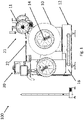
- a device 100 for winding strip-shaped material onto at least one spool 10 is shown.
- the winding of strip-shaped material is understood to mean both winding and unwinding of the material. This means the device can be used for both purposes.
- Strip material is mostly raw material and/or solid material, such as metal strip, which has been formed in a manufacturing machine. These are mostly punching machines that produce contact elements for electrical engineering, for example. In principle, other material can also be used as the strip-shaped material.
- the wound tapes by a release material z. B. separated by a release paper.
- the strip-shaped material comes out of the production machine and is fed to a receiving area of the device 100 in the area of a feed device 20 . From there, the material passes through a feed channel 22, which usually dips into the coil 10, to the coil 10, which rotates about a coil axis 14. A rotary drive 18 is provided for this purpose.
- a separating material for example a separating paper, can also be provided, which is also fed to the spool 10 via a separating material spool 11 and a separating material feed device 21 .
- the entire device 100 is controlled via a control device (not shown), which is arranged, for example, in a control cabinet 16 in the machine frame 12 .
- the Figures 4 to 10 show the feeder 20 ( Figures 4 to 6 ) and part of the feeding device 20 ( Figures 7 to 10 ) closer.
- the feed device 20 has a feed channel 22 and a plate 42 which is preferably designed as a horizontally arranged bearing surface, the feed channel 22 resting at least partially on the plate 42 .
- the bearing surface and thus the plate 42 can be of any desired design, as long as it is ensured that the feed channel rests on it.
- the bearing surface can also be pivoted together with the insertion channel.
- the feed channel 22 is mounted in a floating manner relative to the plate 42, ie the feed channel 22 and the plate 42 are not rigidly connected to one another, so that a relative movement of the feed channel 22 relative to the plate 42 is possible.
- the feeder 20 mounted on the machine frame 12, wherein the plate 42 in the embodiment in the Figures 4 to 6 is firmly connected to the feeder 20.
- the part of the feeder 20 is in the embodiment in the Figures 7 to 10 can be fastened to the feed device 20, for example to a bearing block 56 ( Figures 4 to 6 ).
- the feeder 20 may further include a cover 26 having a window 34 and a handle 36 whereby the cover 26 can be flipped up and the web material inspected. This results in a sample box for sampling the manufactured parts.
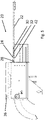
- the feed channel 22 is in the Figures 7 to 10 limited floating in its movement. Any movement of the feed channel in any direction is shown in the embodiment in figure 9 limited, for example, by the fact that one end 44 of the feed channel 22 dips into an opening 52 of the bearing block 56 in the tape feed device 20 and the end 44 is designed in such a way that the opening 52 allows the movement of the feed channel 22 in at least one direction due to the geometry of the end 44 limited.
- the end 44 of the feed channel 22 has extensions 45, preferably curved extensions 45, which reach through the opening 52, whereby these extensions 45 limit the movement of the feed channel 22 on both sides when the feed channel 22 moves relative to the plate 42, since the extensions 45 abut the opening inner wall 53 of the opening 52.
- the geometry of the opening 52 and/or the end 44 can be matched to one another in such a way that a limited mobility of the feed channel 22 is achieved with at least one degree of freedom.
- the holding elements 24 are pivoted at a point 32 .
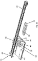
- the figures 11 and 12 show the feed channel 22 and the plate 42 in detail.
- at least part of the feed channel 22 is designed to at least partially fill up at least one recess 40 in the plate 42 and/or at least part of the plate 42 is designed to at least partially fill out at least one recess in the feed channel 22.
- the plate 42 has a recess 40 .
- the feed channel 22 is attached to a centering part 38 with the aid of a holder 48 , which is designed to at least partially fill the recess 40 .
- the bracket 48 in figure 8 has holes 50 through which the feed channel 22 is attached to the centering part 38 by means 46, for example screws.
- the feed channel 22 it is also conceivable for the feed channel 22 to have a recess 40 and for the centering part 38 to be attached to the plate 42 via a holder 48, for example.
- the centering part 38 can be part of the feed channel 22 and/or the plate 42 .
- the feed channel 22 collides, e.g. with a bobbin to be inserted or replaced, it is pushed to the side, causing the centering plate 38 to detach from the recess 40 of the plate 42.
- this movement of the feed channel 22 is limited by the end 44 of the feed channel 22 in that at some point the end 44 is pressed against the opening inner wall 53 of the opening 52 and thus limits the movement of the feed channel 22 .
- the feed channel 22 can be quickly and easily brought back into the original position, namely in the recess 40 of the plate 42, with the aid of the centering part 38, so that an adjustment and orientation of the feed channel 22 is simplified.
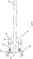
- the holding elements 24 in figure 13 press the feed channel 22 and the plate 42 against each other, preferably with the help of elastic means 28, for example a spring.
- the holding elements 24 press, for example, the feed channel 22 and the plate 42 against one another indirectly via the centering part 38, the holding elements 24 more preferably being attached to the plate 42.
- the recess 40 and/or the filling 41 preferably has a rounded shape.
- the recess 40 in the plate 42 has a rounded shape.
- the filling 41 of the centering part 38 also has a rounded shape. Due to the rounded shape, the feed channel 22 or the centering part 38 attached to it via the holder 48 can move out of the recess 40 of the plate 42 as jerk-free and/or impact-free as possible in the event of a collision, without the filling 41 of the centering part 38 at a specific point gets stuck and there is a sudden jerk.
- the feed channel 22 can be quickly and easily realigned in relation to the plate 42 with the aid of the centering part 38 by the centering part 38 being pushed into the recess 40 of the plate 42 or even again itself falls back there and preferably snaps into place there.
- At least one “giving in” and/or a movement of the feed channel 22 can be detected using at least one sensor 58 .
- the senor 58 is preferably arranged in a further recess 45 in the recess 40 .
- the sensor can be an inductive, optical or electronic sensor, for example. If the feed channel 22 collides, the sensor 58 registers a movement of the feed channel 22 and, for example, sends a signal to the control device to stop the winding process.
- the figures 13 and 14 12 show the feed channel 22 after a collision, for example with a coil 10 (not shown).
- the feed channel is moved a little, for example in the horizontal direction, with the holding elements 24 being pushed upwards by the elastic means 28 so that the feed channel 22 can “snap” out of the recess 40 of the plate 42 via the centering part 38 .
- the figures 13 and 14 show this condition.
- a displacement of the feed channel 22 relative to the plate 42 can be clearly seen.
- the end 44 of the feed channel 22 limits the movement of the feed channel 22 in such a way that the end 44 is pressed against the inside 53 of the opening 52 by the movement of the feed channel 22 .
- the feed channel 22 is "folded up".
- the elastic elements 28 are pressed together, as a result of which the feed channel 22 and the plate 42 are no longer pressed against one another, so that the feed channel 22 can be completely removed from the feed device 20 by "folding it up”. This is also advantageous, for example, when servicing the device 100, the feed device 20 and/or the feed channel 20.
Landscapes
- Engineering & Computer Science (AREA)
- Mechanical Engineering (AREA)
- Advancing Webs (AREA)
- Processes Specially Adapted For Manufacturing Cables (AREA)
- Controlling Rewinding, Feeding, Winding, Or Abnormalities Of Webs (AREA)
- Storage Of Web-Like Or Filamentary Materials (AREA)
Claims (12)
- Appareil (100) pour enrouler un matériau en bande sur au moins une bobine (10) avec au moins un dispositif d'amenée (20) pour amener le matériau en bande à la ou les bobine(s), dans lequel le dispositif d'amenée (20) présente au moins un canal d'amenée (22) et au moins une plaque (42), sur laquelle se trouve au moins partiellement le canal d'amenée (22), caractérisé en ce que le canal d'amenée (22) est monté flottant par rapport à la plaque (42).
- Appareil selon la revendication 1, caractérisé en ce que le canal d'amenée (22) est monté avec un flottement limité dans son déplacement.
- Appareil selon la revendication 2, caractérisé en ce qu'au moins une extrémité (44) du canal d'amenée (22) s'enfonce au moins partiellement dans une ouverture (52) dans le dispositif d'amenée (20) et l'extrémité (44) est réalisée de telle sorte que l'ouverture (52) limite le déplacement du canal d'amenée (22) sur la base de la géométrie de l'extrémité (44) et/ou de l'ouverture (52) dans au moins une direction.
- Appareil selon l'une des revendications précédentes, caractérisé en ce qu'au moins un élément de maintien (24) presse l'une contre l'autre au moins une partie du canal d'amenée (22) et au moins une partie de la plaque (42).
- Appareil selon l'une des revendications précédentes, caractérisé en ce qu'au moins une partie du canal d'amenée (22) est conçue pour le remplissage (41) au moins partiel d'au moins un évidement (40) dans la plaque (42) et/ou en ce qu'au moins une partie de la plaque (42) est conçue pour le remplissage au moins partiel d'au moins un évidement dans le canal d'amenée (22).
- Appareil selon la revendication 5, caractérisé en ce qu'au moins une partie de centrage (38) est prévue, laquelle est conçue pour le remplissage (41) au moins partiel d'au moins un évidement (40).
- Appareil selon la revendication 5 ou 6, caractérisé en ce qu'au moins une partie de centrage (38) prolonge le canal d'amenée (22) ou la plaque (42).
- Appareil selon l'une des revendications 4 à 7, caractérisé en ce qu'au moins un élément de maintien (24) presse l'un contre l'autre, à l'aide d'au moins un moyen élastique (28), le canal d'amenée (22) et la plaque (42).
- Appareil selon l'une des revendications 4 à 8, caractérisé en ce que l'élément de maintien (24) prolonge la plaque (42).
- Appareil selon l'une des revendications 5 à 9, caractérisé en ce que l'évidement (40) et/ou le remplissage (41) présente(nt) une forme arrondie.
- Appareil selon l'une des revendications précédentes, caractérisé en ce qu'au moins un « relâchement » et/ou un déplacement du canal d'amenée (22) est détectable à l'aide d'au moins un capteur (58).
- Appareil selon la revendication 11, caractérisé en ce que l'évidement (40) présente au moins un autre évidement (54), dans lequel le capteur (58) est disposé.
Applications Claiming Priority (1)
| Application Number | Priority Date | Filing Date | Title |
|---|---|---|---|
| DE102019216832.9A DE102019216832B4 (de) | 2019-10-31 | 2019-10-31 | Vorrichtung zum Wickeln von bandförmigem Material |
Publications (2)
| Publication Number | Publication Date |
|---|---|
| EP3819036A1 EP3819036A1 (fr) | 2021-05-12 |
| EP3819036B1 true EP3819036B1 (fr) | 2022-08-24 |
Family
ID=73029908
Family Applications (1)
| Application Number | Title | Priority Date | Filing Date |
|---|---|---|---|
| EP20204083.8A Active EP3819036B1 (fr) | 2019-10-31 | 2020-10-27 | Dispositif d'enroulement d'une matière en forme de bande |
Country Status (4)
| Country | Link |
|---|---|
| EP (1) | EP3819036B1 (fr) |
| DE (1) | DE102019216832B4 (fr) |
| ES (1) | ES2931205T3 (fr) |
| PL (1) | PL3819036T3 (fr) |
Family Cites Families (5)
| Publication number | Priority date | Publication date | Assignee | Title |
|---|---|---|---|---|
| DE8534634U1 (de) * | 1985-12-10 | 1986-04-10 | Bauer, Heinz, 7531 Neulingen | Vorrichtung zum Aufwickeln von mit Stanzungen und gegebenenfalls Prägungen versehenen Formbändern |
| KR910000613B1 (ko) * | 1986-05-14 | 1991-01-28 | 린테크 가부시끼가이샤 | 전자부품이 장치된 기록용 테이프의 감기방법과 그 장치 |
| DE8908818U1 (de) * | 1989-07-20 | 1989-09-07 | Bauer, Heinz, 7531 Neulingen | Zuführungseinrichtung für Formbänder zu einer Aufwickelvorrichtung |
| DE102013000808B4 (de) * | 2013-01-17 | 2018-03-29 | Suba Holding Gmbh + Co.Kg | Vorrichtung zum Aufwickeln von bandförmigem Material |
| DE102014222756A1 (de) * | 2014-11-07 | 2016-05-12 | Leicht Stanzautomation Gmbh | Vorrichtung zum Aufwickeln von bandförmigem Material |
-
2019
- 2019-10-31 DE DE102019216832.9A patent/DE102019216832B4/de not_active Expired - Fee Related
-
2020
- 2020-10-27 ES ES20204083T patent/ES2931205T3/es active Active
- 2020-10-27 PL PL20204083.8T patent/PL3819036T3/pl unknown
- 2020-10-27 EP EP20204083.8A patent/EP3819036B1/fr active Active
Also Published As
| Publication number | Publication date |
|---|---|
| DE102019216832B4 (de) | 2023-02-16 |
| DE102019216832A1 (de) | 2021-05-06 |
| PL3819036T3 (pl) | 2023-01-02 |
| ES2931205T3 (es) | 2022-12-27 |
| EP3819036A1 (fr) | 2021-05-12 |
Similar Documents
| Publication | Publication Date | Title |
|---|---|---|
| EP2452790B1 (fr) | Station de traitement pour une estampilleuse et procédé de sortie de feuilles d'ébauche | |
| EP2399715A1 (fr) | Station de dépôt et de séparation des usages pour une machine à estamper des cintres | |
| DE102007028434B3 (de) | Vollautomatischer Niederhalter für ein Formwerkzeug | |
| DE102007020495A1 (de) | Bogenstanz- und -prägemaschine und Verfahren zur Bogenausrichtung | |
| DE60025375T2 (de) | Schieber, abzieher, belader, entlader und bearbeitungsvorrichtung | |
| EP2701860A1 (fr) | Monture d'outil pour presse plieuse | |
| EP2698332A2 (fr) | Dispositif d'enroulement d'un matériau en forme de bande sur des bobines | |
| DE102019216832B4 (de) | Vorrichtung zum Wickeln von bandförmigem Material | |
| EP1985419B1 (fr) | Dispositif de coupe destiné à raccourcir des ceintures de composant, dispositif d'alimentation et automate d'implantation | |
| DE102020105062A1 (de) | Drucker zum Bedrucken von Markierer-Karten mit Markierern zum Markieren elektrischer Geräte | |
| EP3290370B1 (fr) | Dispositif d'alimentation de fil | |
| EP2014589A2 (fr) | Presse de découpage et de cannelage et procédé destiné à l'orientation des feuilles | |
| EP2762432B1 (fr) | Procédé de surveillance destiné à éviter la collision d'une poinçonneuse avec un balai de freinage | |
| EP0121704B1 (fr) | Installation de transfert d'ordures ou moyen d'un container à accoupler à une presse à ordures | |
| WO2020120587A1 (fr) | Dispositif équipé d'un moteur électrique pour la mise à disposition de matériau d'emballage et procédé pour faire fonctionner un dispositif de mise à disposition de matériau d'emballage | |
| EP3435498B1 (fr) | Dispositif de changement d'outil de sertissage et système de sertissage et procédé de changement d'un premier outil de sertissage disposé dans un processus dans une presse de sertissage contre un second outil de sertissage | |
| DE202010017139U1 (de) | Crimpmaschine für unterschiedliche Crimp- und Pressprozesse, insbesondere zur Kabelkonfektionierung | |
| EP3216709B1 (fr) | Systeme de compartiment comprenant plusieurs compartiments de reception adjacents paralleles destines a recevoir des sachets de feuilles | |
| DE202007012353U1 (de) | Bogenstanz- und -prägemaschine | |
| EP1397302B1 (fr) | Procede pour aligner une feuille | |
| EP4274036B1 (fr) | Outil de confection de câble et utilisation d'au moins un capteur pour déterminer la position sur un tel outil | |
| EP1985420A1 (fr) | Dispositif de coupe destiné à raccourcir des ceintures de composant, dispositif d'alimentation et automate d'implantation | |
| WO2009015760A2 (fr) | Dispositif de transport pivotant pour des pièces de matière plate | |
| DE202014101283U1 (de) | Abstandshalteelement zum Positionieren eines Stanzbogens zu einer Ausbrechplatte und Anordnung mit einem Abstandshalteelement | |
| DE10318691B4 (de) | Klemmmechanismus einer verstellbaren Lenksäule |
Legal Events
| Date | Code | Title | Description |
|---|---|---|---|
| PUAI | Public reference made under article 153(3) epc to a published international application that has entered the european phase |
Free format text: ORIGINAL CODE: 0009012 |
|
| STAA | Information on the status of an ep patent application or granted ep patent |
Free format text: STATUS: THE APPLICATION HAS BEEN PUBLISHED |
|
| AK | Designated contracting states |
Kind code of ref document: A1 Designated state(s): AL AT BE BG CH CY CZ DE DK EE ES FI FR GB GR HR HU IE IS IT LI LT LU LV MC MK MT NL NO PL PT RO RS SE SI SK SM TR |
|
| STAA | Information on the status of an ep patent application or granted ep patent |
Free format text: STATUS: REQUEST FOR EXAMINATION WAS MADE |
|
| 17P | Request for examination filed |
Effective date: 20211105 |
|
| RBV | Designated contracting states (corrected) |
Designated state(s): AL AT BE BG CH CY CZ DE DK EE ES FI FR GB GR HR HU IE IS IT LI LT LU LV MC MK MT NL NO PL PT RO RS SE SI SK SM TR |
|
| GRAP | Despatch of communication of intention to grant a patent |
Free format text: ORIGINAL CODE: EPIDOSNIGR1 |
|
| STAA | Information on the status of an ep patent application or granted ep patent |
Free format text: STATUS: GRANT OF PATENT IS INTENDED |
|
| INTG | Intention to grant announced |
Effective date: 20220317 |
|
| GRAS | Grant fee paid |
Free format text: ORIGINAL CODE: EPIDOSNIGR3 |
|
| GRAA | (expected) grant |
Free format text: ORIGINAL CODE: 0009210 |
|
| STAA | Information on the status of an ep patent application or granted ep patent |
Free format text: STATUS: THE PATENT HAS BEEN GRANTED |
|
| AK | Designated contracting states |
Kind code of ref document: B1 Designated state(s): AL AT BE BG CH CY CZ DE DK EE ES FI FR GB GR HR HU IE IS IT LI LT LU LV MC MK MT NL NO PL PT RO RS SE SI SK SM TR |
|
| REG | Reference to a national code |
Ref country code: CH Ref legal event code: EP |
|
| REG | Reference to a national code |
Ref country code: IE Ref legal event code: FG4D Free format text: LANGUAGE OF EP DOCUMENT: GERMAN |
|
| REG | Reference to a national code |
Ref country code: AT Ref legal event code: REF Ref document number: 1513285 Country of ref document: AT Kind code of ref document: T Effective date: 20220915 Ref country code: DE Ref legal event code: R096 Ref document number: 502020001577 Country of ref document: DE |
|
| REG | Reference to a national code |
Ref country code: LT Ref legal event code: MG9D |
|
| REG | Reference to a national code |
Ref country code: ES Ref legal event code: FG2A Ref document number: 2931205 Country of ref document: ES Kind code of ref document: T3 Effective date: 20221227 |
|
| REG | Reference to a national code |
Ref country code: NL Ref legal event code: MP Effective date: 20220824 |
|
| PG25 | Lapsed in a contracting state [announced via postgrant information from national office to epo] |
Ref country code: SE Free format text: LAPSE BECAUSE OF FAILURE TO SUBMIT A TRANSLATION OF THE DESCRIPTION OR TO PAY THE FEE WITHIN THE PRESCRIBED TIME-LIMIT Effective date: 20220824 Ref country code: RS Free format text: LAPSE BECAUSE OF FAILURE TO SUBMIT A TRANSLATION OF THE DESCRIPTION OR TO PAY THE FEE WITHIN THE PRESCRIBED TIME-LIMIT Effective date: 20220824 Ref country code: PT Free format text: LAPSE BECAUSE OF FAILURE TO SUBMIT A TRANSLATION OF THE DESCRIPTION OR TO PAY THE FEE WITHIN THE PRESCRIBED TIME-LIMIT Effective date: 20221226 Ref country code: NO Free format text: LAPSE BECAUSE OF FAILURE TO SUBMIT A TRANSLATION OF THE DESCRIPTION OR TO PAY THE FEE WITHIN THE PRESCRIBED TIME-LIMIT Effective date: 20221124 Ref country code: NL Free format text: LAPSE BECAUSE OF FAILURE TO SUBMIT A TRANSLATION OF THE DESCRIPTION OR TO PAY THE FEE WITHIN THE PRESCRIBED TIME-LIMIT Effective date: 20220824 Ref country code: LV Free format text: LAPSE BECAUSE OF FAILURE TO SUBMIT A TRANSLATION OF THE DESCRIPTION OR TO PAY THE FEE WITHIN THE PRESCRIBED TIME-LIMIT Effective date: 20220824 Ref country code: LT Free format text: LAPSE BECAUSE OF FAILURE TO SUBMIT A TRANSLATION OF THE DESCRIPTION OR TO PAY THE FEE WITHIN THE PRESCRIBED TIME-LIMIT Effective date: 20220824 Ref country code: FI Free format text: LAPSE BECAUSE OF FAILURE TO SUBMIT A TRANSLATION OF THE DESCRIPTION OR TO PAY THE FEE WITHIN THE PRESCRIBED TIME-LIMIT Effective date: 20220824 |
|
| PG25 | Lapsed in a contracting state [announced via postgrant information from national office to epo] |
Ref country code: IS Free format text: LAPSE BECAUSE OF FAILURE TO SUBMIT A TRANSLATION OF THE DESCRIPTION OR TO PAY THE FEE WITHIN THE PRESCRIBED TIME-LIMIT Effective date: 20221224 Ref country code: HR Free format text: LAPSE BECAUSE OF FAILURE TO SUBMIT A TRANSLATION OF THE DESCRIPTION OR TO PAY THE FEE WITHIN THE PRESCRIBED TIME-LIMIT Effective date: 20220824 Ref country code: GR Free format text: LAPSE BECAUSE OF FAILURE TO SUBMIT A TRANSLATION OF THE DESCRIPTION OR TO PAY THE FEE WITHIN THE PRESCRIBED TIME-LIMIT Effective date: 20221125 |
|
| PG25 | Lapsed in a contracting state [announced via postgrant information from national office to epo] |
Ref country code: SM Free format text: LAPSE BECAUSE OF FAILURE TO SUBMIT A TRANSLATION OF THE DESCRIPTION OR TO PAY THE FEE WITHIN THE PRESCRIBED TIME-LIMIT Effective date: 20220824 Ref country code: RO Free format text: LAPSE BECAUSE OF FAILURE TO SUBMIT A TRANSLATION OF THE DESCRIPTION OR TO PAY THE FEE WITHIN THE PRESCRIBED TIME-LIMIT Effective date: 20220824 Ref country code: DK Free format text: LAPSE BECAUSE OF FAILURE TO SUBMIT A TRANSLATION OF THE DESCRIPTION OR TO PAY THE FEE WITHIN THE PRESCRIBED TIME-LIMIT Effective date: 20220824 |
|
| REG | Reference to a national code |
Ref country code: DE Ref legal event code: R097 Ref document number: 502020001577 Country of ref document: DE |
|
| PG25 | Lapsed in a contracting state [announced via postgrant information from national office to epo] |
Ref country code: SK Free format text: LAPSE BECAUSE OF FAILURE TO SUBMIT A TRANSLATION OF THE DESCRIPTION OR TO PAY THE FEE WITHIN THE PRESCRIBED TIME-LIMIT Effective date: 20220824 Ref country code: MC Free format text: LAPSE BECAUSE OF FAILURE TO SUBMIT A TRANSLATION OF THE DESCRIPTION OR TO PAY THE FEE WITHIN THE PRESCRIBED TIME-LIMIT Effective date: 20220824 Ref country code: EE Free format text: LAPSE BECAUSE OF FAILURE TO SUBMIT A TRANSLATION OF THE DESCRIPTION OR TO PAY THE FEE WITHIN THE PRESCRIBED TIME-LIMIT Effective date: 20220824 |
|
| REG | Reference to a national code |
Ref country code: BE Ref legal event code: MM Effective date: 20221031 |
|
| PG25 | Lapsed in a contracting state [announced via postgrant information from national office to epo] |
Ref country code: LU Free format text: LAPSE BECAUSE OF NON-PAYMENT OF DUE FEES Effective date: 20221027 Ref country code: AL Free format text: LAPSE BECAUSE OF FAILURE TO SUBMIT A TRANSLATION OF THE DESCRIPTION OR TO PAY THE FEE WITHIN THE PRESCRIBED TIME-LIMIT Effective date: 20220824 |
|
| PLBE | No opposition filed within time limit |
Free format text: ORIGINAL CODE: 0009261 |
|
| STAA | Information on the status of an ep patent application or granted ep patent |
Free format text: STATUS: NO OPPOSITION FILED WITHIN TIME LIMIT |
|
| 26N | No opposition filed |
Effective date: 20230525 |
|
| PG25 | Lapsed in a contracting state [announced via postgrant information from national office to epo] |
Ref country code: SI Free format text: LAPSE BECAUSE OF FAILURE TO SUBMIT A TRANSLATION OF THE DESCRIPTION OR TO PAY THE FEE WITHIN THE PRESCRIBED TIME-LIMIT Effective date: 20220824 |
|
| PG25 | Lapsed in a contracting state [announced via postgrant information from national office to epo] |
Ref country code: BE Free format text: LAPSE BECAUSE OF NON-PAYMENT OF DUE FEES Effective date: 20221031 |
|
| PG25 | Lapsed in a contracting state [announced via postgrant information from national office to epo] |
Ref country code: IE Free format text: LAPSE BECAUSE OF NON-PAYMENT OF DUE FEES Effective date: 20221027 |
|
| PG25 | Lapsed in a contracting state [announced via postgrant information from national office to epo] |
Ref country code: CY Free format text: LAPSE BECAUSE OF FAILURE TO SUBMIT A TRANSLATION OF THE DESCRIPTION OR TO PAY THE FEE WITHIN THE PRESCRIBED TIME-LIMIT Effective date: 20220824 |
|
| PG25 | Lapsed in a contracting state [announced via postgrant information from national office to epo] |
Ref country code: MK Free format text: LAPSE BECAUSE OF FAILURE TO SUBMIT A TRANSLATION OF THE DESCRIPTION OR TO PAY THE FEE WITHIN THE PRESCRIBED TIME-LIMIT Effective date: 20220824 |
|
| PG25 | Lapsed in a contracting state [announced via postgrant information from national office to epo] |
Ref country code: HU Free format text: LAPSE BECAUSE OF FAILURE TO SUBMIT A TRANSLATION OF THE DESCRIPTION OR TO PAY THE FEE WITHIN THE PRESCRIBED TIME-LIMIT; INVALID AB INITIO Effective date: 20201027 Ref country code: BG Free format text: LAPSE BECAUSE OF FAILURE TO SUBMIT A TRANSLATION OF THE DESCRIPTION OR TO PAY THE FEE WITHIN THE PRESCRIBED TIME-LIMIT Effective date: 20220824 |
|
| PG25 | Lapsed in a contracting state [announced via postgrant information from national office to epo] |
Ref country code: MT Free format text: LAPSE BECAUSE OF FAILURE TO SUBMIT A TRANSLATION OF THE DESCRIPTION OR TO PAY THE FEE WITHIN THE PRESCRIBED TIME-LIMIT Effective date: 20220824 |
|
| REG | Reference to a national code |
Ref country code: CH Ref legal event code: U11 Free format text: ST27 STATUS EVENT CODE: U-0-0-U10-U11 (AS PROVIDED BY THE NATIONAL OFFICE) Effective date: 20251101 |
|
| PG25 | Lapsed in a contracting state [announced via postgrant information from national office to epo] |
Ref country code: TR Free format text: LAPSE BECAUSE OF FAILURE TO SUBMIT A TRANSLATION OF THE DESCRIPTION OR TO PAY THE FEE WITHIN THE PRESCRIBED TIME-LIMIT Effective date: 20220824 |
|
| PGFP | Annual fee paid to national office [announced via postgrant information from national office to epo] |
Ref country code: DE Payment date: 20250911 Year of fee payment: 6 |
|
| PGFP | Annual fee paid to national office [announced via postgrant information from national office to epo] |
Ref country code: GB Payment date: 20251024 Year of fee payment: 6 |
|
| PGFP | Annual fee paid to national office [announced via postgrant information from national office to epo] |
Ref country code: AT Payment date: 20251021 Year of fee payment: 6 |
|
| PGFP | Annual fee paid to national office [announced via postgrant information from national office to epo] |
Ref country code: IT Payment date: 20251031 Year of fee payment: 6 |
|
| PGFP | Annual fee paid to national office [announced via postgrant information from national office to epo] |
Ref country code: FR Payment date: 20251029 Year of fee payment: 6 |
|
| PGFP | Annual fee paid to national office [announced via postgrant information from national office to epo] |
Ref country code: CH Payment date: 20251101 Year of fee payment: 6 |
|
| PGFP | Annual fee paid to national office [announced via postgrant information from national office to epo] |
Ref country code: CZ Payment date: 20251015 Year of fee payment: 6 |
|
| PGFP | Annual fee paid to national office [announced via postgrant information from national office to epo] |
Ref country code: PL Payment date: 20251016 Year of fee payment: 6 |
|
| PGFP | Annual fee paid to national office [announced via postgrant information from national office to epo] |
Ref country code: ES Payment date: 20251114 Year of fee payment: 6 |