EP3819112B1 - Device for capacitively measuring the powder level in a filling device of a rotary press - Google Patents
Device for capacitively measuring the powder level in a filling device of a rotary press Download PDFInfo
- Publication number
- EP3819112B1 EP3819112B1 EP20201517.8A EP20201517A EP3819112B1 EP 3819112 B1 EP3819112 B1 EP 3819112B1 EP 20201517 A EP20201517 A EP 20201517A EP 3819112 B1 EP3819112 B1 EP 3819112B1
- Authority
- EP
- European Patent Office
- Prior art keywords
- measuring
- filling
- measuring electrode
- electrode
- filling pipe
- Prior art date
- Legal status (The legal status is an assumption and is not a legal conclusion. Google has not performed a legal analysis and makes no representation as to the accuracy of the status listed.)
- Active
Links
Images


Classifications
-
- G—PHYSICS
- G01—MEASURING; TESTING
- G01F—MEASURING VOLUME, VOLUME FLOW, MASS FLOW OR LIQUID LEVEL; METERING BY VOLUME
- G01F23/00—Indicating or measuring liquid level or level of fluent solid material, e.g. indicating in terms of volume or indicating by means of an alarm
- G01F23/22—Indicating or measuring liquid level or level of fluent solid material, e.g. indicating in terms of volume or indicating by means of an alarm by measuring physical variables, other than linear dimensions, pressure or weight, dependent on the level to be measured, e.g. by difference of heat transfer of steam or water
- G01F23/26—Indicating or measuring liquid level or level of fluent solid material, e.g. indicating in terms of volume or indicating by means of an alarm by measuring physical variables, other than linear dimensions, pressure or weight, dependent on the level to be measured, e.g. by difference of heat transfer of steam or water by measuring variations of capacity or inductance of capacitors or inductors arising from the presence of liquid or fluent solid material in the electric or electromagnetic fields
- G01F23/263—Indicating or measuring liquid level or level of fluent solid material, e.g. indicating in terms of volume or indicating by means of an alarm by measuring physical variables, other than linear dimensions, pressure or weight, dependent on the level to be measured, e.g. by difference of heat transfer of steam or water by measuring variations of capacity or inductance of capacitors or inductors arising from the presence of liquid or fluent solid material in the electric or electromagnetic fields by measuring variations in capacitance of capacitors
- G01F23/268—Indicating or measuring liquid level or level of fluent solid material, e.g. indicating in terms of volume or indicating by means of an alarm by measuring physical variables, other than linear dimensions, pressure or weight, dependent on the level to be measured, e.g. by difference of heat transfer of steam or water by measuring variations of capacity or inductance of capacitors or inductors arising from the presence of liquid or fluent solid material in the electric or electromagnetic fields by measuring variations in capacitance of capacitors mounting arrangements of probes
-
- B—PERFORMING OPERATIONS; TRANSPORTING
- B30—PRESSES
- B30B—PRESSES IN GENERAL
- B30B15/00—Details of, or accessories for, presses; Auxiliary measures in connection with pressing
- B30B15/30—Feeding material to presses
- B30B15/302—Feeding material in particulate or plastic state to moulding presses
- B30B15/308—Feeding material in particulate or plastic state to moulding presses in a continuous manner, e.g. for roller presses, screw extrusion presses
-
- G—PHYSICS
- G01—MEASURING; TESTING
- G01N—INVESTIGATING OR ANALYSING MATERIALS BY DETERMINING THEIR CHEMICAL OR PHYSICAL PROPERTIES
- G01N27/00—Investigating or analysing materials by the use of electric, electrochemical, or magnetic means
- G01N27/02—Investigating or analysing materials by the use of electric, electrochemical, or magnetic means by investigating impedance
- G01N27/22—Investigating or analysing materials by the use of electric, electrochemical, or magnetic means by investigating impedance by investigating capacitance
- G01N27/221—Investigating or analysing materials by the use of electric, electrochemical, or magnetic means by investigating impedance by investigating capacitance by investigating the dielectric properties
-
- B—PERFORMING OPERATIONS; TRANSPORTING
- B30—PRESSES
- B30B—PRESSES IN GENERAL
- B30B11/00—Presses specially adapted for forming shaped articles from material in particulate or plastic state, e.g. briquetting presses, tabletting presses
- B30B11/005—Control arrangements
-
- B—PERFORMING OPERATIONS; TRANSPORTING
- B30—PRESSES
- B30B—PRESSES IN GENERAL
- B30B11/00—Presses specially adapted for forming shaped articles from material in particulate or plastic state, e.g. briquetting presses, tabletting presses
- B30B11/02—Presses specially adapted for forming shaped articles from material in particulate or plastic state, e.g. briquetting presses, tabletting presses using a ram exerting pressure on the material in a moulding space
- B30B11/08—Presses specially adapted for forming shaped articles from material in particulate or plastic state, e.g. briquetting presses, tabletting presses using a ram exerting pressure on the material in a moulding space co-operating with moulds carried by a turntable
-
- B—PERFORMING OPERATIONS; TRANSPORTING
- B30—PRESSES
- B30B—PRESSES IN GENERAL
- B30B15/00—Details of, or accessories for, presses; Auxiliary measures in connection with pressing
- B30B15/30—Feeding material to presses
- B30B15/302—Feeding material in particulate or plastic state to moulding presses
-
- B—PERFORMING OPERATIONS; TRANSPORTING
- B30—PRESSES
- B30B—PRESSES IN GENERAL
- B30B15/00—Details of, or accessories for, presses; Auxiliary measures in connection with pressing
- B30B15/32—Discharging presses
-
- G—PHYSICS
- G01—MEASURING; TESTING
- G01B—MEASURING LENGTH, THICKNESS OR SIMILAR LINEAR DIMENSIONS; MEASURING ANGLES; MEASURING AREAS; MEASURING IRREGULARITIES OF SURFACES OR CONTOURS
- G01B7/00—Measuring arrangements characterised by the use of electric or magnetic techniques
- G01B7/02—Measuring arrangements characterised by the use of electric or magnetic techniques for measuring length, width or thickness
- G01B7/06—Measuring arrangements characterised by the use of electric or magnetic techniques for measuring length, width or thickness for measuring thickness
- G01B7/08—Measuring arrangements characterised by the use of electric or magnetic techniques for measuring length, width or thickness for measuring thickness using capacitive means
- G01B7/082—Height gauges
-
- G—PHYSICS
- G01—MEASURING; TESTING
- G01F—MEASURING VOLUME, VOLUME FLOW, MASS FLOW OR LIQUID LEVEL; METERING BY VOLUME
- G01F23/00—Indicating or measuring liquid level or level of fluent solid material, e.g. indicating in terms of volume or indicating by means of an alarm
- G01F23/22—Indicating or measuring liquid level or level of fluent solid material, e.g. indicating in terms of volume or indicating by means of an alarm by measuring physical variables, other than linear dimensions, pressure or weight, dependent on the level to be measured, e.g. by difference of heat transfer of steam or water
- G01F23/26—Indicating or measuring liquid level or level of fluent solid material, e.g. indicating in terms of volume or indicating by means of an alarm by measuring physical variables, other than linear dimensions, pressure or weight, dependent on the level to be measured, e.g. by difference of heat transfer of steam or water by measuring variations of capacity or inductance of capacitors or inductors arising from the presence of liquid or fluent solid material in the electric or electromagnetic fields
- G01F23/263—Indicating or measuring liquid level or level of fluent solid material, e.g. indicating in terms of volume or indicating by means of an alarm by measuring physical variables, other than linear dimensions, pressure or weight, dependent on the level to be measured, e.g. by difference of heat transfer of steam or water by measuring variations of capacity or inductance of capacitors or inductors arising from the presence of liquid or fluent solid material in the electric or electromagnetic fields by measuring variations in capacitance of capacitors
- G01F23/265—Indicating or measuring liquid level or level of fluent solid material, e.g. indicating in terms of volume or indicating by means of an alarm by measuring physical variables, other than linear dimensions, pressure or weight, dependent on the level to be measured, e.g. by difference of heat transfer of steam or water by measuring variations of capacity or inductance of capacitors or inductors arising from the presence of liquid or fluent solid material in the electric or electromagnetic fields by measuring variations in capacitance of capacitors for discrete levels
-
- G—PHYSICS
- G01—MEASURING; TESTING
- G01N—INVESTIGATING OR ANALYSING MATERIALS BY DETERMINING THEIR CHEMICAL OR PHYSICAL PROPERTIES
- G01N27/00—Investigating or analysing materials by the use of electric, electrochemical, or magnetic means
- G01N27/02—Investigating or analysing materials by the use of electric, electrochemical, or magnetic means by investigating impedance
- G01N27/22—Investigating or analysing materials by the use of electric, electrochemical, or magnetic means by investigating impedance by investigating capacitance
- G01N27/226—Construction of measuring vessels; Electrodes therefor
Definitions
- the invention relates to a device for capacitively measuring the powder level in a filling device for filling cavities of a die disk of a rotary press with powder material to be pressed in the rotary press, comprising a filling tube of the filling device.
- the invention also relates to a rotary press, comprising a rotor that can be rotated by means of a rotary drive, the rotor having an upper punch guide for upper punches of the rotary press and a lower punch guide for lower punches of the rotary press, as well as a die writer arranged between the punch guides, the punches having cavities Die plate work together, further comprising a filling device, through which powder material to be pressed is filled into the cavities of the die plate, the filling device comprising a filling tube, further comprising at least one upper pressure device and at least one lower pressure device, which in operation with the upper punches and with the lower stamps for pressing the powder material in the cavities of the die disk cooperate, further comprising an ejection device in which compacts produced in the cavities are ejected.
- powder material filled into cavities is pressed into compacts, especially tablets, using upper and lower punches.
- the powder material is filled into the cavities using a filling device of the rotary press.
- Such filling devices regularly include a filling tube through which the powder material usually falls into a filling chamber due to gravity, from which it in turn usually reaches the cavities by gravity. It is desirable to check the filling level in the filling device, especially in the filling tube monitored to ensure sufficient powder availability at all times. It has been proposed to arrange sensors inside the filling pipe for this purpose. However, the arrangement of a sensor in the powder material flow leads to disturbances in the powder flow, such as bridging. This can undesirably affect powder availability.
- EP 2 400 275 A1 a device for non-invasive, non-contact capacitive level measurement of, for example, bulk materials in a container is described.
- the filling level sensor does not come into contact with the filling medium whose filling level is to be determined. Rather, electrodes are provided which are arranged like an opened plate capacitor and between which a high-frequency alternating electrical field is generated, which penetrates the material to be measured non-destructively.
- the capacity of the capacitor thus formed depends on the permittivity of the filling material.
- the filling material to be measured has a different permittivity than air. In this way, different levels of coverage of the sensor surface with the material to be measured leads to a different capacitance of the capacitor. From this it is possible to draw conclusions about the filling level of the material in the container.
- EP 2 400 275 A1 proposed to arrange several measuring electrodes in different horizontal planes, which define a measuring surface with vertical extent, and to provide at least one reference electrode, which defines a reference surface with vertical extent. Each of the several measuring electrodes forms a capacitor together with the reference electrode. At least two capacitors are measured and the measured values are related to each other.
- active shielding is also known from practice, in which an electrode serving as a shield is controlled to the same voltage potential as the measuring electrodes during the measurement. While this active shielding can reduce the influence of external sources of interference, there is still a need for improved protection against interference in capacitive level measurement.
- a capacitive measuring device for measuring the liquid level in a tank is known.
- the sensor has an anode and cathode attached to the outside of a measuring tube, which are shielded by an electrically conductive sensor holder at ground potential to reduce external interference.
- a tablet press is known with a riser pipe arranged above the rotor of the press, which ends in a filling shoe.
- the filling shoe is used to feed a product to be compressed.
- a sensor for detecting the fill level is arranged at the filling level of the product targeted in the filling shoe.
- a capacitive level sensor can be provided as a sensor.
- a filling level indicator device for determining the height of a column of tobacco extending downwards in a shaft.
- the device has an electrode for capacitive Level measurement, which is shielded by a shield electrode against external electrical stray fields and interference fields.
- the shielding electrode is supplied with a voltage by a voltage tracking amplifier whose input is connected to the electrode.
- the invention is based on the object of providing a device and a rotary press of the type mentioned at the outset, with which a level measurement in the filling device of a rotary press is possible without disturbing the powder flow and while minimizing external interference.
- the invention solves the problem in that a first measuring electrode is arranged on the filling tube, which forms a first electrical capacitor with a reference electrode, so that an electric field can be formed between the first measuring electrode and the reference electrode, and that the first measuring electrode is on its side facing away from the filling tube is covered by an electrically conductive protective shield, the protective shield being at ground potential.
- the invention solves the problem in that it comprises a device according to the invention for capacitively measuring the powder level in the filling device.
- the rotary press can in particular be a rotary tablet press. Powder material to be processed in the rotary press is fed to the die disk through the filling tube.
- the powder material can be conveyed through the filling device and the filling pipe due to gravity.
- the filling pipe can therefore form a downpipe.
- the filling tube can be arranged suitably for this purpose.
- the longitudinal axis of the filling tube can be sufficiently inclined relative to the horizontal, in particular, for example, run vertically.
- the filling device can also have at least one filling chamber into which the powder material passes from the filling tube.
- the powder material is fed from the filling chamber to the cavities of the matrix disk, in particular due to gravity, where the powder material is pressed in a manner known per se by the upper and lower punches to form compacts, in particular tablets.
- the cavities can be formed directly through holes in the matrix disk.
- releasably attached die sleeves in which the cavities are formed can also be arranged in the die disk.
- a first measuring electrode is arranged on the filling tube. It interacts with a reference electrode of the device. Together, the electrodes form an electrical capacitor, similar to a plate capacitor.
- the first measuring electrode extends over a certain measuring range in the axial direction of the filling tube.
- the reference electrode can also extend over this area.
- an electric field is formed between the measuring electrode and the reference electrode, which penetrates the interior of the filling tube and thus the powder material to be measured non-destructively.
- the capacitance of the capacitor depends on the permittivity of the medium penetrated by the electric field. Air has a different permittivity than the powder material to be processed in the rotary press.
- the reference electrode can also comprise several (sub)reference electrodes or be formed by several (sub)reference electrodes.
- the first measuring electrode is covered, in particular completely covered, by an electrically conductive and grounded protective shield on its side facing away from the filling tube.
- the filling tube can be made of a metal, such as stainless steel, for example.
- the protective shield can also be made of metal, for example aluminum or stainless steel.
- the present inventors have recognized that the conveying of a powder material through a filling device, in particular a filling pipe, leads to different problems compared to measuring the level of a liquid in a closed tank.
- conveying the powder material through the filling device leads to a static charge on the powder material, which can influence the measurement results.
- owns the powder material to be processed in a rotary press has a lower permittivity than the liquid to be measured in a tank in the prior art.
- the electrically conductive protective shielding according to the invention which is at ground potential. It reliably shields the first measuring electrode against external sources of electromagnetic interference.
- the filling level of the powder material to be processed in a rotary press can be reliably determined in the filling tube. At the same time, complex arrangements with a large number of measuring electrodes and complicated and unreliable plausibility considerations are avoided.
- the internal geometry of the filling tube remains intact and the powder flow is not disturbed or influenced by the measuring sensors. External disturbances, for example from electrical systems in the rotary press or due to contact by an operator, are not mathematically eliminated from the measurement result, unlike in the prior art, but are effectively suppressed from the outset.
- the first measuring electrode is arranged in an electrically non-conductive holding section, the holding section being arranged on the filling tube.
- a non-conductive plastic such as POM can be used.
- the holding section can be covered as a whole from the outside by the protective shield according to the invention.
- a jacket pocket for the first measuring electrode and, if necessary, further measuring electrodes can be arranged in the holding section.
- the holding section is arranged in a recess in the filling tube.
- the filling tube then has a cutout in which the holding section with the first measuring electrode is arranged.
- an electrically conductive filling tube section of the filling device located before and/or after the filling tube provided with the first measuring electrode can also be at ground potential.
- the inventors have recognized that in the course of conveying through the filling device, in particular the filling tube, the powder material becomes statically charged. According to the inventors' findings, this is caused by the friction between the powder material and the components of the filling device that carry the powder material, in particular the filling tube.
- grounding an electrically conductive filling tube section located upstream of the filling tube provided with the first measuring electrode this static charge is eliminated before the capacitive level measurement, so that it cannot falsify the subsequent measurement.
- the reference electrode and/or the filling tube provided with the first measuring electrode can also be at ground potential. In this way, in addition to a particularly reliable measurement and additional electromagnetic shielding, a static charge on the powder material in the filling tube provided with the first measuring electrode can also be prevented or eliminated.
- the reference electrode can also be arranged on the filling tube provided with the first measuring electrode.
- the reference electrode can then also be covered, in particular completely, by the electrically conductive protective shield on its side facing away from the filling tube.
- the reference electrode can also be arranged in the electrically non-conductive holding section.
- the reference electrode can be formed by the filling tube provided with the first measuring electrode.
- the first measuring electrode forms the electrical capacitor directly with the filling tube as a reference electrode.
- an enlarged reference electrode can therefore be used as a basis for the capacity measurement.
- the filling tube and possibly also the protective shield are also at ground potential, a particularly accurate and reliable capacitance measurement can be carried out.
- a second measuring electrode is further arranged on the filling tube, wherein the second measuring electrode and the reference electrode form a second electrical capacitor, so that an electric field can be formed between the second measuring electrode and the reference electrode, and wherein the Measuring range of the second measuring electrode is selected so that it is completely covered at all times by powder material located in the filling tube during operation of the rotary press.
- the expansion in The longitudinal direction of the filling tube and thus the measuring range of the second measuring electrode is smaller than the extent of the first measuring electrode in the longitudinal direction of the filling tube and thus its measuring range.
- the extent of the second measuring electrode can be no more than 15%, preferably no more than 10%, of the first measuring electrode.
- the second measuring electrode can in particular be located parallel to the first measuring electrode and be essentially flush with its lower end or protrude beyond the lower end of the first measuring electrode.
- the provision of such a second measuring electrode, which is completely covered by the powder material located in the filling tube during operation of the rotary press, allows fill level measurement even with different powder materials or changes in the composition of the powder material. If the second measuring electrode is completely covered with powder material, it can be assumed that the electric field formed between this and the reference electrode is formed completely within the powder material. If the extent of the second measuring electrode in the axial direction of the filling tube is known, the fill level of the powder material can be calculated from the capacitance measured for the first measuring electrode, even with different powder materials and without complex additional calibration measures. A measurement is therefore possible regardless of the powder material or any changes in the composition of the powder material. It has been shown that the accuracy of the measurement can be further improved in this way.
- a third measuring electrode is further arranged on the filling tube, wherein the third measuring electrode and the reference electrode form a third electrical capacitor, so that an electric field can be formed between the third measuring electrode and the reference electrode, and wherein the The measuring range of the third measuring electrode is selected so that it is always above the filling level of the rotary press during operation Powder material is located in the filling tube.
- the expansion in the longitudinal direction of the filling tube and thus the measuring range of the third measuring electrode is in turn smaller than the expansion of the first measuring electrode in the longitudinal direction of the filling tube and thus its measuring range.
- the extent of the third measuring electrode can in turn be no more than 15%, preferably no more than 10%, of the first measuring electrode.
- the third measuring electrode can in particular be located parallel to the first measuring electrode and be essentially flush with its upper end or protrude beyond the upper end of the first measuring electrode.
- the reference electrode can comprise several (sub)reference electrodes. However, it can also only include one reference electrode. Some or all of the measuring electrodes can form an electrical capacitor with a reference electrode in the manner explained. In particular, if the reference electrode comprises several (sub-)reference electrodes, some or all of the measuring electrodes can also form an electrical capacitor in the manner explained with different ones of the (sub-)reference electrodes.
- the second and/or the third measuring electrode can also be covered, in particular completely covered, by the electrically conductive protective shield on its side facing away from the filling tube be. Furthermore, the second and/or the third measuring electrode can also be arranged in the electrically non-conductive holding section. As already explained, a further improvement in the measurement result can be achieved in this way.
- the protective shield can form an active protective shield, which is controlled to the same electrical potential as the first measuring electrode and/or the second measuring electrode and/or the third measuring electrode during a level measurement. So-called active shielding can be carried out in order to further improve the shielding against external sources of interference and thus the measurement result.
- a control and evaluation device can be provided which controls the measuring and reference electrodes during operation of the rotary press and determines the fill level of the powder material in the filling tube based on the measurement data from the measuring and reference electrodes.
- the control and evaluation device can be part of a control and evaluation device of the rotary press or can be designed separately from it.
- the measuring and/or reference electrodes can be arranged on essentially non-flexible PCB circuit boards.
- Such classic PCB circuit boards usually have a thickness of more than 1 mm. This leads to additional insulation, which can further minimize external interference.
- the rotary tablet press shown comprises a rotor which is driven in rotation by a rotary drive (not shown) and has a die disk 10 which has a plurality of cavities 12.
- the cavities 12 can be formed, for example, by holes in the matrix disk 10.
- the rotor further comprises a plurality of upper punches 14 guided in an upper punch guide 13 and a plurality of lower punches 16 guided in a lower punch guide 15, which rotate synchronously with the die disk 10.
- Each pair of upper stamp 14 and lower stamp 16 is assigned to a cavity 12.
- the axial movement of the upper punches 14 and lower punches 16 as the rotor rotates is controlled by upper cam elements 18 and lower cam elements 20.
- the rotary tablet press further comprises a filling device 22 which has a filling chamber 24.
- the filling device 22 also includes a funnel-shaped filling material reservoir 26, which is connected to the filling chamber 24 via a filling pipe 28.
- a funnel-shaped filling material reservoir 26 which is connected to the filling chamber 24 via a filling pipe 28.
- powdery filling material reaches the filling chamber 24 via the filling tube 28 due to gravity and from there, due to gravity, into the cavities 12 of the die disk 10 via a filling opening provided on the underside of the filling chamber 24.
- the rotary tablet press also includes a printing device 30.
- the printing device 30 has a pre-printing device with an upper pre-pressure roller 32 and a lower pre-pressure roller 34 as well as a main printing device with an upper main pressure roller 36 and a lower main pressure roller 38.
- the rotary tablet press includes an ejection device 40, in the present case with a Stripper 42, which feeds the tablets 44 produced in the rotary press to a tablet drain 46.
- An evaluation and control device 48 controls the operation of the rotary press and is connected, among other things, to the rotary drive of the rotor via lines (not shown).
- a device 50 for capacitively measuring the powder level in the filling tube 28 is also arranged on the filling tube 28.
- the device 50 is also connected to the evaluation and control device 48.
- the device 50 for capacitively measuring the powder level is shown in different views.
- the filling tube 28 has a recess 52 in which a holding section 54 made of an electrically non-conductive material, for example a plastic such as POM, is arranged.
- the holding section 54 carries a first measuring electrode 56 which extends in the axial direction of the filling tube 28 and parallel second and third measuring electrodes 58, 60 arranged in relation to the first measuring electrode 56, each of which extends parallel to and over approximately 10% of the length of the first measuring electrode 56.
- the second measuring electrode 58 is arranged in the area of the lower end of the first measuring electrode 56 and the third measuring electrode 60 in the area of the upper end of the first measuring electrode 56, as in particular in Figure 5 to recognize.
- the holding section 54 and with it the measuring electrodes 56, 58 and 60 are also covered on their side facing away from the filling tube 28 by an electrically non-conductive protective shield 62, which is at ground potential.
- the protective shield 62 is not shown for illustrative purposes.
- the filling pipe 28 is also at ground potential in the example shown.
- the filling tube 28 and the protective shield 62 can be made of a metal, for example.
- the filling tube 28 can be made of stainless steel and the protective shield 62 can be made of aluminum.
- the filling tube 28 forms a reference electrode for the measuring electrodes 56, 58 and 60.
- the measuring electrodes 56, 58 and 60 thus form three electrical capacitors with the filling tube 28 as a reference electrode, so that between the measuring electrodes 56, 58 and 60 and the reference electrode 28 can each form an electric field.
- the second measuring electrode 58 can be completely covered at any time with powder material located in the filling tube 28, while the third measuring electrode 60 can be located above the level of the powder material in the filling tube 28.
- the first measuring electrode 56 forms a measuring area for measuring the powder level in the filling tube 28.
- an electric field is formed between the measuring electrodes 56, 58 and 60 and the filling tube 28 serving as a reference electrode, controlled by the evaluation and control device 48, and the capacitance of the capacitors formed is measured, again by the evaluation and Control device 48.
- the evaluation and evaluation are based on the capacity measurement Control device 48 on the powder level in the filling tube 28.
- External interference can be largely minimized by the protective shield 62 at ground potential.
- the second and third measuring electrodes 58, 60 can be used to eliminate influences on the measurement result resulting from changes in the powder material or properties of the filling tube 28.
Landscapes
- Engineering & Computer Science (AREA)
- Physics & Mathematics (AREA)
- Mechanical Engineering (AREA)
- Power Engineering (AREA)
- General Physics & Mathematics (AREA)
- Chemical & Material Sciences (AREA)
- Fluid Mechanics (AREA)
- Thermal Sciences (AREA)
- Electromagnetism (AREA)
- Health & Medical Sciences (AREA)
- Immunology (AREA)
- Pathology (AREA)
- General Health & Medical Sciences (AREA)
- Biochemistry (AREA)
- Analytical Chemistry (AREA)
- Life Sciences & Earth Sciences (AREA)
- Electrochemistry (AREA)
- Chemical Kinetics & Catalysis (AREA)
- Measurement Of Levels Of Liquids Or Fluent Solid Materials (AREA)
Description
Die Erfindung betrifft eine Vorrichtung zum kapazitiven Messen des Pulverfüllstands in einer Fülleinrichtung zum Befüllen von Kavitäten einer Matrizenscheibe einer Rundläuferpresse mit in der Rundläuferpresse zu verpressendem Pulvermaterial, umfassend ein Füllrohr der Fülleinrichtung.The invention relates to a device for capacitively measuring the powder level in a filling device for filling cavities of a die disk of a rotary press with powder material to be pressed in the rotary press, comprising a filling tube of the filling device.
Die Erfindung betrifft außerdem eine Rundläuferpresse, umfassend einen mittels eines Drehantriebs drehbaren Rotor, wobei der Rotor eine obere Stempelführung für obere Stempel der Rundläuferpresse und eine untere Stempelführung für untere Stempel der Rundläuferpresse sowie eine zwischen den Stempelführungen angeordnete Matrizenschreibe aufweist, wobei die Stempel mit Kavitäten der Matrizenscheibe zusammenwirken, weiter umfassend eine Fülleinrichtung, durch die zu verpressendes Pulvermaterial in die Kavitäten der Matrizenscheibe gefüllt wird, wobei die Fülleinrichtung ein Füllrohr umfasst, weiter umfassend mindestens eine obere Druckeinrichtung und mindestens eine untere Druckeinrichtung, die im Betrieb mit den oberen Stempeln und mit den unteren Stempeln zum Verpressen des Pulvermaterials in den Kavitäten der Matrizenscheibe zusammenwirken, weiter umfassend eine Auswurfeinrichtung, in der in den Kavitäten erzeugte Pressling ausgeworfen werden.The invention also relates to a rotary press, comprising a rotor that can be rotated by means of a rotary drive, the rotor having an upper punch guide for upper punches of the rotary press and a lower punch guide for lower punches of the rotary press, as well as a die writer arranged between the punch guides, the punches having cavities Die plate work together, further comprising a filling device, through which powder material to be pressed is filled into the cavities of the die plate, the filling device comprising a filling tube, further comprising at least one upper pressure device and at least one lower pressure device, which in operation with the upper punches and with the lower stamps for pressing the powder material in the cavities of the die disk cooperate, further comprising an ejection device in which compacts produced in the cavities are ejected.
In Rundläuferpressen wird in Kavitäten gefülltes Pulvermaterial mittels Ober- und Unterstempeln zu Presslingen, insbesondere Tabletten, verpresst. Das Pulvermaterial wird mittels einer Fülleinrichtung der Rundläuferpresse in die Kavitäten gefüllt. Derartige Fülleinrichtungen umfassen regelmäßig ein Füllrohr, durch das das Pulvermaterial in der Regel schwerkraftbedingt in eine Füllkammer fällt, aus der es wiederum in der Regel mittels Schwerkraft in die Kavitäten gelangt. Dabei ist es wünschenswert, den Füllstand in der Fülleinrichtung, insbesondere in dem Füllrohr zu überwachen, um jederzeit eine ausreichende Pulververfügbarkeit sicherzustellen. Es ist vorgeschlagen worden, hierzu Sensoren im Inneren des Füllrohrs anzuordnen. Die Anordnung eines Sensors im Pulvermaterialfluss führt allerdings zu Störungen des Pulverflusses, wie zum Beispiel eine Brückenbildung. Dies kann die Pulververfügbarkeit in unerwünschter Weise beeinträchtigen.In rotary presses, powder material filled into cavities is pressed into compacts, especially tablets, using upper and lower punches. The powder material is filled into the cavities using a filling device of the rotary press. Such filling devices regularly include a filling tube through which the powder material usually falls into a filling chamber due to gravity, from which it in turn usually reaches the cavities by gravity. It is desirable to check the filling level in the filling device, especially in the filling tube monitored to ensure sufficient powder availability at all times. It has been proposed to arrange sensors inside the filling pipe for this purpose. However, the arrangement of a sensor in the powder material flow leads to disturbances in the powder flow, such as bridging. This can undesirably affect powder availability.
In
Ein Problem stellen dabei externe Störeinflüsse dar, wie zum Beispiel externe elektromagnetische Felder oder externe Objekte, wie zum Beispiel eine Hand einer Bedienperson in der Nähe der Messelektroden. Um die Störungsanfälligkeit für Einflüsse von außen zu verringern, wird in
Durch Plausibilitätsprüfungen sollen äußere Einflüsse als Störquellen rechnerisch eliminiert werden. Die bekannte Vorrichtung ist jedoch von erheblichem konstruktivem und auswertetechnischem Aufwand. Auch bietet die Plausibilitätsbetrachtung nicht immer ein zuverlässiges Ergebnis.Plausibility checks are intended to mathematically eliminate external influences as sources of interference. However, the known device requires considerable design and evaluation effort. The plausibility analysis also does not always provide a reliable result.
Zum Schutz vor externen Störquellen bei der kapazitiven Füllstandsmessung ist aus der Praxis weiterhin das sogenannte Active Shielding bekannt, bei dem eine als Schild dienende Elektrode bei der Messung auf das gleiche Spannungspotential angesteuert wird wie die Messelektroden. Während durch dieses Active Shielding der Einfluss externer Störquellen verringert werden kann, besteht dennoch weiterhin ein Bedürfnis nach einem verbesserten Schutz gegenüber Störungen bei der kapazitiven Füllstandsmessung.To protect against external sources of interference in capacitive level measurement, so-called active shielding is also known from practice, in which an electrode serving as a shield is controlled to the same voltage potential as the measuring electrodes during the measurement. While this active shielding can reduce the influence of external sources of interference, there is still a need for improved protection against interference in capacitive level measurement.
Aus
Aus
Aus
Ausgehend von dem erläuterten Stand der Technik liegt der Erfindung die Aufgabe zugrunde, eine Vorrichtung und eine Rundläuferpresse der eingangs genannten Art bereitzustellen, mit denen eine Füllstandsmessung in der Fülleinrichtung einer Rundläuferpresse ohne Störung des Pulverflusses und unter Minimierung externer Störeinflüsse möglich ist.Based on the explained prior art, the invention is based on the object of providing a device and a rotary press of the type mentioned at the outset, with which a level measurement in the filling device of a rotary press is possible without disturbing the powder flow and while minimizing external interference.
Die Erfindung löst die Aufgabe durch die Gegenstände der Ansprüche 1 und 14. Vorteilhafte Ausgestaltungen finden sich in den abhängigen Ansprüchen, der Beschreibung und den Figuren.The invention solves the problem through the subjects of
Für eine Vorrichtung der eingangs genannten Art löst die Erfindung die Aufgabe dadurch, dass an dem Füllrohr eine erste Messelektrode angeordnet ist, die mit einer Referenzelektrode einen ersten elektrischen Kondensator ausbildet, so dass zwischen der ersten Messelektrode und der Referenzelektrode ein elektrisches Feld ausbildbar ist, und dass die erste Messelektrode auf ihrer dem Füllrohr abgewandten Seite durch eine elektrisch leitfähige Schutzabschirmung abgedeckt ist, wobei die Schutzabschirmung auf Erdpotential liegt.For a device of the type mentioned at the outset, the invention solves the problem in that a first measuring electrode is arranged on the filling tube, which forms a first electrical capacitor with a reference electrode, so that an electric field can be formed between the first measuring electrode and the reference electrode, and that the first measuring electrode is on its side facing away from the filling tube is covered by an electrically conductive protective shield, the protective shield being at ground potential.
Für eine Rundläuferpresse der eingangs genannten Art löst die Erfindung die Aufgabe dadurch, dass sie eine erfindungsgemäße Vorrichtung zum kapazitiven Messen des Pulverfüllstands in der Fülleinrichtung umfasst.For a rotary press of the type mentioned at the outset, the invention solves the problem in that it comprises a device according to the invention for capacitively measuring the powder level in the filling device.
Bei der Rundläuferpresse kann es sich insbesondere um eine Rundläufertablettenpresse handeln. In der Rundläuferpresse zu verarbeitendes Pulvermaterial wird durch das Füllrohr der Matrizenscheibe zugeführt. Das Pulvermaterial kann schwerkraftbedingt durch die Fülleinrichtung und das Füllrohr gefördert werden. Das Füllrohr kann also ein Fallrohr bilden. Das Füllrohr kann dazu geeignet angeordnet sein. Zum Beispiel kann die Längsachse des Füllrohrs gegenüber der Horizontalen ausreichend geneigt sein, insbesondere zum Beispiel vertikal verlaufen. Die Fülleinrichtung kann weiterhin mindestens eine Füllkammer aufweisen, in die das Pulvermaterial aus dem Füllrohr gelangt. Aus der Füllkammer wird das Pulvermaterial den Kavitäten der Matrizenscheibe zugeführt, insbesondere wiederum schwerkraftbedingt, wo das Pulvermaterial in an sich bekannter Weise durch die Ober- und Unterstempel zu Presslingen, insbesondere Tabletten, verpresst wird. Die Kavitäten können unmittelbar durch Bohrungen der Matrizenscheibe gebildet sein. Es können in der Matrizenscheibe aber auch lösbar befestigte Matrizenhülsen angeordnet sein, in denen die Kavitäten ausgebildet sind.The rotary press can in particular be a rotary tablet press. Powder material to be processed in the rotary press is fed to the die disk through the filling tube. The powder material can be conveyed through the filling device and the filling pipe due to gravity. The filling pipe can therefore form a downpipe. The filling tube can be arranged suitably for this purpose. For example, the longitudinal axis of the filling tube can be sufficiently inclined relative to the horizontal, in particular, for example, run vertically. The filling device can also have at least one filling chamber into which the powder material passes from the filling tube. The powder material is fed from the filling chamber to the cavities of the matrix disk, in particular due to gravity, where the powder material is pressed in a manner known per se by the upper and lower punches to form compacts, in particular tablets. The cavities can be formed directly through holes in the matrix disk. However, releasably attached die sleeves in which the cavities are formed can also be arranged in the die disk.
Zum kapazitiven Messen des Pulverfüllstands in dem Füllrohr ist an dem Füllrohr eine erste Messelektrode angeordnet. Sie wirkt mit einer Referenzelektrode der Vorrichtung zusammen. Zusammen bilden die Elektroden einen elektrischen Kondensator, ähnlich einem Plattenkondensator. Die erste Messelektrode erstreckt sich über einen gewissen Messbereich in Axialrichtung des Füllrohrs. Auch die Referenzelektrode kann sich über diesen Bereich erstrecken. Zwischen der ersten Messelektrode und der Referenzelektrode wird im Betrieb ein elektrisches Feld ausgebildet, dass das Innere des Füllrohrs und damit das zu messende Pulvermaterial zerstörungsfrei durchdringt. Die Kapazität des Kondensators hängt wie erläutert von der Permittivität des vom elektrischen Feld durchdrungenen Mediums ab. So weist Luft eine andere Permittivität auf als das in der Rundläuferpresse zu verarbeitende Pulvermaterial. Dadurch kann anhand einer Kapazitätsmessung des Kondensators auf den Grad der Überdeckung der Elektroden durch Pulvermaterial geschlossen werden. Daraus wiederum kann auf den Füllstand des Pulvermaterials in dem Füllrohr geschlossen werden. Natürlich können auch mehrere erste Messelektroden vorgesehen sein. Die Referenzelektrode kann ebenfalls mehrere (Unter-)Referenzelektroden umfassen bzw. durch mehrere (Unter-)Referenzelektroden gebildet sein.For capacitively measuring the powder level in the filling tube, a first measuring electrode is arranged on the filling tube. It interacts with a reference electrode of the device. Together, the electrodes form an electrical capacitor, similar to a plate capacitor. The first measuring electrode extends over a certain measuring range in the axial direction of the filling tube. The reference electrode can also extend over this area. Between the first During operation, an electric field is formed between the measuring electrode and the reference electrode, which penetrates the interior of the filling tube and thus the powder material to be measured non-destructively. As explained, the capacitance of the capacitor depends on the permittivity of the medium penetrated by the electric field. Air has a different permittivity than the powder material to be processed in the rotary press. This means that the degree of coverage of the electrodes by powder material can be determined by measuring the capacitance of the capacitor. This in turn allows conclusions to be drawn about the fill level of the powder material in the filling tube. Of course, several first measuring electrodes can also be provided. The reference electrode can also comprise several (sub)reference electrodes or be formed by several (sub)reference electrodes.
Erfindungsgemäß ist die erste Messelektrode auf ihrer dem Füllrohr abgewandten Seite durch eine elektrisch leitfähige und geerdete Schutzabschirmung abgedeckt, insbesondere vollständig abgedeckt. Das Füllrohr kann zum Beispiel aus einem Metall, wie Edelstahl bestehen. Die Schutzabschirmung kann ebenfalls aus Metall, zum Beispiel Aluminium oder ebenfalls aus Edelstahl bestehen. Erfindungsgemäß ist erkannt worden, dass die im Stand der Technik vorgeschlagene Methode des Active Shielding für die Füllstandsmessung von Pulvermaterial in einer Fülleinrichtung einer Rundläuferpresse nicht ausreichend ist um auch bei der erfindungsgemäßen Anwendung trotz etwaiger externer Störquellen zuverlässige Messergebnisse zu erhalten. Im Stand der Technik wird das Active Shielding für einen geschlossenen Tank vorgeschlagen und zum Messen einer Flüssigkeit. Die vorliegenden Erfinder haben allerdings erkannt, dass gerade die Förderung eines Pulvermaterials durch eine Fülleinrichtung, insbesondere ein Füllrohr, im Vergleich zur Füllstandsmessung einer Flüssigkeit in einem geschlossenen Tank zu anderen Problemstellungen führt. So führt einerseits das Fördern des Pulvermaterials durch die Fülleinrichtung nach Erkenntnissen der Erfinder zu einer statischen Aufladung des Pulvermaterials, die die Messergebnisse beeinflussen kann. Außerdem besitzt das in einer Rundläuferpresse zu verarbeitende Pulvermaterial eine geringere Permittivität als die im Stand der Technik in einem Tank zu messende Flüssigkeit. Diese Unterschiede bei der Anwendung machen bei der erfindungsgemäßen Anwendung eine höhere Messgenauigkeit erforderlich. Dies wiederum führt dazu, dass das Ausschließen externer Störungen, zum Beispiel durch externe elektromagnetische Felder oder in der Nähe der Messvorrichtung befindliche Personen, noch zuverlässiger erfolgen muss.According to the invention, the first measuring electrode is covered, in particular completely covered, by an electrically conductive and grounded protective shield on its side facing away from the filling tube. The filling tube can be made of a metal, such as stainless steel, for example. The protective shield can also be made of metal, for example aluminum or stainless steel. According to the invention, it has been recognized that the active shielding method proposed in the prior art for measuring the fill level of powder material in a filling device of a rotary press is not sufficient to obtain reliable measurement results even in the application according to the invention despite any external sources of interference. In the prior art, active shielding is proposed for a closed tank and for measuring a liquid. However, the present inventors have recognized that the conveying of a powder material through a filling device, in particular a filling pipe, leads to different problems compared to measuring the level of a liquid in a closed tank. On the one hand, according to the inventors' findings, conveying the powder material through the filling device leads to a static charge on the powder material, which can influence the measurement results. Also owns the powder material to be processed in a rotary press has a lower permittivity than the liquid to be measured in a tank in the prior art. These differences in application make higher measurement accuracy necessary for the application according to the invention. This in turn means that the exclusion of external interference, for example due to external electromagnetic fields or people in the vicinity of the measuring device, must be done even more reliably.
Dies wird durch die erfindungsgemäße elektrisch leitfähige und auf Erdpotential liegende Schutzabschirmung erreicht. Sie schirmt die erste Messelektrode sicher gegen externe elektromagnetische Störquellen ab. Damit kann erfindungsgemäß der Füllstand des in einer Rundläuferpresse zu verarbeitenden Pulvermaterials in dem Füllrohr zuverlässig ermittelt werden. Gleichzeitig werden aufwendige Anordnungen mit einer Vielzahl von Messelektroden und komplizierte und unzuverlässige Plausibilitätsbetrachtungen vermieden. Die Innengeometrie des Füllrohrs bleibt störungsfrei erhalten und der Pulverfluss wird nicht von der Messsensorik gestört oder beeinflusst. Externe Störungen beispielsweise von elektrischen Anlagen in der Rundläuferpresse oder durch Berührungen durch einen Bediener werden anders als im Stand der Technik nicht rechnerisch aus dem Messergebnis eliminiert, sondern von vornherein wirksam unterdrückt.This is achieved by the electrically conductive protective shielding according to the invention which is at ground potential. It reliably shields the first measuring electrode against external sources of electromagnetic interference. According to the invention, the filling level of the powder material to be processed in a rotary press can be reliably determined in the filling tube. At the same time, complex arrangements with a large number of measuring electrodes and complicated and unreliable plausibility considerations are avoided. The internal geometry of the filling tube remains intact and the powder flow is not disturbed or influenced by the measuring sensors. External disturbances, for example from electrical systems in the rotary press or due to contact by an operator, are not mathematically eliminated from the measurement result, unlike in the prior art, but are effectively suppressed from the outset.
Die erste Messelektrode ist in einem elektrisch nicht leitfähigen Halteabschnitt angeordnet, wobei der Halteabschnitt an dem Füllrohr angeordnet ist. Auf diese Weise wird eine weiter verbesserte Abschirmung erreicht. Zum Einsatz kommen kann zum Beispiel ein nicht leitfähiger Kunststoff, wie POM. Der Halteabschnitt kann als Ganzes durch die erfindungsgemäße Schutzabschirmung nach außen abgedeckt sein. In dem Halteabschnitt kann eine Manteltasche für die erste Messelektrode und gegebenenfalls weitere Messelektroden angeordnet sein.The first measuring electrode is arranged in an electrically non-conductive holding section, the holding section being arranged on the filling tube. In this way, further improved shielding is achieved. For example, a non-conductive plastic such as POM can be used. The holding section can be covered as a whole from the outside by the protective shield according to the invention. A jacket pocket for the first measuring electrode and, if necessary, further measuring electrodes can be arranged in the holding section.
Weiterhin ist der Halteabschnitt in einer Aussparung des Füllrohrs angeordnet. Das Füllrohr weist dann einen Ausschnitt auf, in dem der Halteabschnitt mit der ersten Messelektrode angeordnet ist. Auf diese Weise wird ein besonders guter Messzugang zu den Pulvermaterial in dem Füllrohr und damit eine besonders genaue Messung erreicht ohne das Risiko einer Störung des Pulverflusses.Furthermore, the holding section is arranged in a recess in the filling tube. The filling tube then has a cutout in which the holding section with the first measuring electrode is arranged. In this way, particularly good measuring access to the powder material in the filling tube and thus a particularly precise measurement is achieved without the risk of disrupting the powder flow.
Nach einer weiteren Ausgestaltung kann ein vor dem und/oder nach dem mit der ersten Messelektrode versehenen Füllrohr befindlicher elektrisch leitfähiger Füllrohrabschnitt der Fülleinrichtung ebenfalls auf Erdpotential liegen. Wie erläutert, haben die Erfinder erkannt, dass es im Zuge der Förderung durch die Fülleinrichtung, insbesondere das Füllrohr, zu einer statischen Aufladung des Pulvermaterials kommt. Verursacht wird diese nach Erkenntnissen der Erfinder durch die Reibung zwischen dem Pulvermaterial und den das Pulvermaterial führenden Komponenten der Fülleinrichtung, insbesondere das Füllrohr. Durch eine Erdung eines stromauf des mit der ersten Messelektrode versehenen Füllrohrs befindlichen elektrisch leitfähigen Füllrohrabschnitts wird diese statische Aufladung vor der kapazitiven Füllstandsmessung eliminiert, sodass sie die anschließende Messung nicht verfälschen kann. Auch im Zuge der weiteren Pulvermaterialförderung nach der Füllstandsmessung kann es zu einer weiteren/erneuten unerwünschten statischen Aufladung des Pulvermaterials kommen. Diese kann sich negativ auf das Verarbeitungsergebnis in der Rundläuferpresse auswirken. Um dies zu verhindern, kann auch eine Erdung eines sich stromab des mit der ersten Messelektrode versehenen Füllrohrs befindlichen elektrisch leitfähigen Füllrohrabschnitts sinnvoll sein. Auch diese Füllrohrabschnitte können beispielsweise aus einem Metall, wie einem Edelstahl bestehen.According to a further embodiment, an electrically conductive filling tube section of the filling device located before and/or after the filling tube provided with the first measuring electrode can also be at ground potential. As explained, the inventors have recognized that in the course of conveying through the filling device, in particular the filling tube, the powder material becomes statically charged. According to the inventors' findings, this is caused by the friction between the powder material and the components of the filling device that carry the powder material, in particular the filling tube. By grounding an electrically conductive filling tube section located upstream of the filling tube provided with the first measuring electrode, this static charge is eliminated before the capacitive level measurement, so that it cannot falsify the subsequent measurement. Even in the course of further powder material conveyance after the level measurement, further/renewed undesirable static charging of the powder material can occur. This can have a negative impact on the processing results in the rotary press. In order to prevent this, it may also make sense to ground an electrically conductive filling pipe section located downstream of the filling pipe provided with the first measuring electrode. These filling pipe sections can also be made of a metal, such as stainless steel, for example.
Auch die Referenzelektrode und/oder das mit der ersten Messelektrode versehene Füllrohr können auf Erdpotential liegen. Auf diese Weise kann neben einer besonders zuverlässigen Messung und einer zusätzlichen elektromagnetischen Abschirmung auch eine statische Aufladung des Pulvermaterials in dem mit der ersten Messelektrode versehenen Füllrohr verhindert bzw. eliminiert werden.The reference electrode and/or the filling tube provided with the first measuring electrode can also be at ground potential. In this way, in addition to a particularly reliable measurement and additional electromagnetic shielding, a static charge on the powder material in the filling tube provided with the first measuring electrode can also be prevented or eliminated.
Nach einer weiteren Ausgestaltung kann die Referenzelektrode ebenfalls an dem mit der ersten Messelektrode versehenen Füllrohr angeordnet sein. Auch die Referenzelektrode kann dann auf ihrer dem Füllrohr abgewandten Seite durch die elektrisch leitfähige Schutzabschirmung abgedeckt sein, insbesondere vollständig. Auch die Referenzelektrode kann in dem elektrisch nicht leitfähigen Halteabschnitt angeordnet sein.According to a further embodiment, the reference electrode can also be arranged on the filling tube provided with the first measuring electrode. The reference electrode can then also be covered, in particular completely, by the electrically conductive protective shield on its side facing away from the filling tube. The reference electrode can also be arranged in the electrically non-conductive holding section.
Nach einer weiteren Ausgestaltung kann die Referenzelektrode durch das mit der ersten Messelektrode versehene Füllrohr gebildet sein. Auf diese Weise bildet die erste Messelektrode den elektrischen Kondensator direkt mit dem Füllrohr als Referenzelektrode aus. Es kann somit im Vergleich zu der Anordnung der Referenzelektrode an dem Füllrohr eine vergrößerte Referenzelektrode als Basis für die Kapazitätsmessung zum Einsatz kommen. Insbesondere wenn das Füllrohr und gegebenenfalls auch die Schutzabschirmung ebenfalls auf Erdpotential liegen, kann so eine besonders genaue und zuverlässige Kapazitätsmessung erfolgen.According to a further embodiment, the reference electrode can be formed by the filling tube provided with the first measuring electrode. In this way, the first measuring electrode forms the electrical capacitor directly with the filling tube as a reference electrode. In comparison to the arrangement of the reference electrode on the filling tube, an enlarged reference electrode can therefore be used as a basis for the capacity measurement. Particularly if the filling tube and possibly also the protective shield are also at ground potential, a particularly accurate and reliable capacitance measurement can be carried out.
Gemäß einer weiteren Ausgestaltung kann vorgesehen sein, dass an dem Füllrohr weiterhin eine zweite Messelektrode angeordnet ist, wobei die zweite Messelektrode und die Referenzelektrode einen zweiten elektrischen Kondensator ausbilden, so dass zwischen der zweiten Messelektrode und der Referenzelektrode ein elektrisches Feld ausbildbar ist, und wobei der Messbereich der zweiten Messelektrode so gewählt ist, dass er im Betrieb der Rundläuferpresse jederzeit vollständig durch in dem Füllrohr befindliches Pulvermaterial überdeckt ist. Die Ausdehnung in Längsrichtung des Füllrohrs und damit der Messbereich der zweiten Messelektrode ist dabei kleiner als die Ausdehnung der ersten Messelektrode in Längsrichtung des Füllrohrs und damit ihr Messbereich. Beispielsweise kann die Ausdehnung der zweiten Messelektrode nicht mehr als 15 %, vorzugsweise nicht mehr als 10 % der ersten Messelektrode betragen. Die zweite Messelektrode kann sich insbesondere parallel zur ersten Messelektrode befinden und im Wesentlichen bündig mit deren unteren Ende abschließen oder über das untere Ende der ersten Messelektrode hinausragen. Das Vorsehen einer solchen zweiten Messelektrode die im Betrieb der Rundläuferpresse vollständig durch das in dem Füllrohr befindliche Pulvermaterial überdeckt ist, erlaubt eine Füllstandsmessung auch bei unterschiedlichen Pulvermaterialien oder Veränderungen in der Zusammensetzung des Pulvermaterials. So kann bei einer vollständigen Überdeckung der zweiten Messelektrode mit Pulvermaterial davon ausgegangen werden, dass das zwischen dieser und der Referenzelektrode ausgebildete elektrische Feld vollständig innerhalb des Pulvermaterials ausgebildet ist. Bei bekannter Ausdehnung der zweiten Messelektrode in Axialrichtung des Füllrohrs kann rechnerisch aus der für die erste Messelektrode gemessenen Kapazität auch bei unterschiedlichen Pulvermaterialien und ohne aufwendige zusätzliche Kalibriermaßnahmen auf den Füllstand des Pulvermaterials geschlossen werden. Es ist somit eine Messung unabhängig von dem Pulvermaterial bzw. etwaiger Veränderungen der Zusammensetzung des Pulvermaterials möglich. Es hat sich gezeigt, dass auf diese Weise die Genauigkeit der Messung weiter verbessert werden kann.According to a further embodiment, it can be provided that a second measuring electrode is further arranged on the filling tube, wherein the second measuring electrode and the reference electrode form a second electrical capacitor, so that an electric field can be formed between the second measuring electrode and the reference electrode, and wherein the Measuring range of the second measuring electrode is selected so that it is completely covered at all times by powder material located in the filling tube during operation of the rotary press. The expansion in The longitudinal direction of the filling tube and thus the measuring range of the second measuring electrode is smaller than the extent of the first measuring electrode in the longitudinal direction of the filling tube and thus its measuring range. For example, the extent of the second measuring electrode can be no more than 15%, preferably no more than 10%, of the first measuring electrode. The second measuring electrode can in particular be located parallel to the first measuring electrode and be essentially flush with its lower end or protrude beyond the lower end of the first measuring electrode. The provision of such a second measuring electrode, which is completely covered by the powder material located in the filling tube during operation of the rotary press, allows fill level measurement even with different powder materials or changes in the composition of the powder material. If the second measuring electrode is completely covered with powder material, it can be assumed that the electric field formed between this and the reference electrode is formed completely within the powder material. If the extent of the second measuring electrode in the axial direction of the filling tube is known, the fill level of the powder material can be calculated from the capacitance measured for the first measuring electrode, even with different powder materials and without complex additional calibration measures. A measurement is therefore possible regardless of the powder material or any changes in the composition of the powder material. It has been shown that the accuracy of the measurement can be further improved in this way.
Nach einer weiteren Ausgestaltung kann vorgesehen sein, dass an dem Füllrohr weiterhin eine dritte Messelektrode angeordnet ist, wobei die dritte Messelektrode und die Referenzelektrode einen dritten elektrischen Kondensator ausbilden, so dass zwischen der dritten Messelektrode und der Referenzelektrode ein elektrisches Feld ausbildbar ist, und wobei der Messbereich der dritten Messelektrode so gewählt ist, dass er sich im Betrieb der Rundläuferpresse jederzeit oberhalb des Füllstands des Pulvermaterials in dem Füllrohr befindet. Die Ausdehnung in Längsrichtung des Füllrohrs und damit der Messbereich der dritten Messelektrode ist dabei wiederum kleiner als die Ausdehnung der ersten Messelektrode in Längsrichtung des Füllrohrs und damit ihr Messbereich. Beispielsweise kann die Ausdehnung der dritten Messelektrode wiederum nicht mehr als 15 %, vorzugsweise nicht mehr als 10 % der ersten Messelektrode betragen. Die dritte Messelektrode kann sich insbesondere parallel zur ersten Messelektrode befinden und im Wesentlichen bündig mit deren oberen Ende abschließen oder über das obere Ende der ersten Messelektrode hinausragen. Durch eine solche dritte Messelektrode, die im Betrieb der Rundläuferpresse nicht, auch nicht teilweise durch in dem Füllrohr stehendes Pulvermaterial überdeckt ist, kann bei bekannter Ausdehnung der dritten Messelektrode in Axialrichtung des Füllrohrs eine Messung unter Berücksichtigung etwaiger Eigenschaften der Fülleinrichtung, insbesondere des Füllrohrs, erfolgen. Insbesondere können im Betrieb auftretende Veränderungen der Messumgebung ohne Einfluss des Pulvermaterials erkannt und bei der Füllstandsmessung mittels der ersten Messelektrode berücksichtigt werden.According to a further embodiment, it can be provided that a third measuring electrode is further arranged on the filling tube, wherein the third measuring electrode and the reference electrode form a third electrical capacitor, so that an electric field can be formed between the third measuring electrode and the reference electrode, and wherein the The measuring range of the third measuring electrode is selected so that it is always above the filling level of the rotary press during operation Powder material is located in the filling tube. The expansion in the longitudinal direction of the filling tube and thus the measuring range of the third measuring electrode is in turn smaller than the expansion of the first measuring electrode in the longitudinal direction of the filling tube and thus its measuring range. For example, the extent of the third measuring electrode can in turn be no more than 15%, preferably no more than 10%, of the first measuring electrode. The third measuring electrode can in particular be located parallel to the first measuring electrode and be essentially flush with its upper end or protrude beyond the upper end of the first measuring electrode. By means of such a third measuring electrode, which is not, even partially, covered by powder material standing in the filling tube during operation of the rotary press, a measurement can be carried out taking into account any properties of the filling device, in particular of the filling tube, if the extent of the third measuring electrode in the axial direction of the filling tube is known . In particular, changes in the measuring environment that occur during operation can be detected without the influence of the powder material and taken into account when measuring the level using the first measuring electrode.
Wie bereits erläutert, kann die Referenzelektrode mehrere (Unter-)Referenzelektroden umfassen. Sie kann allerdings auch nur eine Referenzelektrode umfassen. Einige oder sämtliche der Messelektroden können mit einer Referenzelektrode in der erläuterten Weise einen elektrischen Kondensator bilden. Insbesondere wenn die Referenzelektrode mehrere (Unter-)Referenzelektroden umfasst, können einige oder sämtliche der Messelektroden jedoch auch einen elektrischen Kondensator in der erläuterten Weise mit unterschiedlichen der (Unter-)Referenzelektroden bilden.As already explained, the reference electrode can comprise several (sub)reference electrodes. However, it can also only include one reference electrode. Some or all of the measuring electrodes can form an electrical capacitor with a reference electrode in the manner explained. In particular, if the reference electrode comprises several (sub-)reference electrodes, some or all of the measuring electrodes can also form an electrical capacitor in the manner explained with different ones of the (sub-)reference electrodes.
Nach einer weiteren Ausgestaltung kann auch die zweite und/oder die dritte Messelektrode auf ihrer dem Füllrohr abgewandten Seite durch die elektrisch leitfähige Schutzabschirmung abgedeckt sein, insbesondere vollständig abgedeckt sein. Weiterhin kann auch die zweite und/oder die dritte Messelektrode in dem elektrisch nicht leitfähigen Halteabschnitt angeordnet sein. Wie bereits erläutert, kann auf diese Weise eine weitere Verbesserung des Messergebnisses erreicht werden.According to a further embodiment, the second and/or the third measuring electrode can also be covered, in particular completely covered, by the electrically conductive protective shield on its side facing away from the filling tube be. Furthermore, the second and/or the third measuring electrode can also be arranged in the electrically non-conductive holding section. As already explained, a further improvement in the measurement result can be achieved in this way.
Nach einer weiteren Ausgestaltung kann die Schutzabschirmung eine aktive Schutzabschirmung bilden, die bei einer Füllstandsmessung auf das gleiche elektrische Potential angesteuert wird wie die erste Messelektrode und/oder die zweite Messelektrode und/oder die dritte Messelektrode. Es kann also ein sogenanntes Active Shielding erfolgen, um die Abschirmung gegenüber externen Störquellen und damit das Messergebnis weiter zu verbessern.According to a further embodiment, the protective shield can form an active protective shield, which is controlled to the same electrical potential as the first measuring electrode and/or the second measuring electrode and/or the third measuring electrode during a level measurement. So-called active shielding can be carried out in order to further improve the shielding against external sources of interference and thus the measurement result.
Nach einer weiteren Ausgestaltung kann eine Steuer- und Auswerteeinrichtung vorgesehen sein, die die Mess- und Referenzelektroden im Betrieb der Rundläuferpresse ansteuert und anhand der Messdaten der Mess- und Referenzelektroden den Füllstand des Pulvermaterials in dem Füllrohr bestimmt. Die Steuer- und Auswerteeinrichtung kann Teil einer Steuer- und Auswerteeinrichtung der Rundläuferpresse oder getrennt hiervon ausgebildet sein.According to a further embodiment, a control and evaluation device can be provided which controls the measuring and reference electrodes during operation of the rotary press and determines the fill level of the powder material in the filling tube based on the measurement data from the measuring and reference electrodes. The control and evaluation device can be part of a control and evaluation device of the rotary press or can be designed separately from it.
Die Mess- und/oder Referenzelektroden können nach einer weiteren Ausgestaltung auf im Wesentlichen nicht flexiblen PCB-Leiterplatten angeordnet sein. Solche klassischen PCB-Leiterplatten weisen eine Dicke von regelmäßig mehr als 1 mm auf. Dies führt zu einer zusätzlichen Isolierung, durch die externe Störeinflüsse weiter minimiert werden können.According to a further embodiment, the measuring and/or reference electrodes can be arranged on essentially non-flexible PCB circuit boards. Such classic PCB circuit boards usually have a thickness of more than 1 mm. This leads to additional insulation, which can further minimize external interference.
Ein Ausführungsbeispiel der Erfindung wird nachfolgend anhand von Figuren näher erläutert. Es zeigen schematisch:
- Fig. 1
- eine erfindungsgemäße Rundläuferpresse in einer abgewickelten Darstellung des Rotors,
- Fig. 2
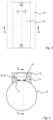
- eine erfindungsgemäße Vorrichtung zum kapazitiven Messen des Pulverfüllstands in der Fülleinrichtung einer Rundläuferpresse in einer Seitenansicht,
- Fig. 3
- eine Schnittansicht entlang der Linie A-A in
Figur 2 , - Fig. 4
- eine Schnittansicht entlang der Linie B-B in
Figur 3 , und - Fig. 5
- die Ansicht aus
Figur 2 mit entfernter Schutzabschirmung.
- Fig. 1
- a rotary press according to the invention in a developed representation of the rotor,
- Fig. 2
- a device according to the invention for capacitively measuring the powder level in the filling device of a rotary press in a side view,
- Fig. 3
- a sectional view along line AA in
Figure 2 , - Fig. 4
- a sectional view along line BB in
Figure 3 , and - Fig. 5
- the view
Figure 2 with protective shield removed.
Soweit nichts anderes angegeben ist, bezeichnen in den Figuren gleiche Bezugszeichen gleiche Gegenstände.Unless otherwise stated, the same reference numbers designate the same objects in the figures.
Die in
Außerdem umfasst die Rundläufertablettenpresse eine Druckeinrichtung 30. Die Druckeinrichtung 30 besitzt eine Vordruckeinrichtung mit einer oberen Vordruckrolle 32 und einer unteren Vordruckrolle 34 sowie eine Hauptdruckeinrichtung mit einer oberen Hauptdruckrolle 36 und einer unteren Hauptdruckrolle 38. Darüber hinaus umfasst die Rundläufertablettenpresse eine Auswurfeinrichtung 40, vorliegend mit einem Abstreifer 42, der die in der Rundläuferpresse hergestellten Tabletten 44 einem Tablettenablauf 46 zuführt.The rotary tablet press also includes a
Eine Auswerte- und Steuereinrichtung 48 steuert den Betrieb der Rundläuferpresse und ist über nicht näher dargestellte Leitungen unter anderem mit dem Drehantrieb des Rotors verbunden.An evaluation and
An dem Füllrohr 28 ist außerdem eine Vorrichtung 50 zum kapazitiven Messen des Pulverfüllstands in dem Füllrohr 28 angeordnet. Die Vorrichtung 50 ist ebenfalls mit der Auswerte- und Steuereinrichtung 48 verbunden.A
In den
Das Füllrohr 28 bildet in dem in den Figuren dargestellten Ausführungsbeispiel eine Referenzelektrode für die Messelektroden 56, 58 und 60. Die Messelektroden 56, 58 und 60 bilden somit drei elektrische Kondensatoren mit dem Füllrohr 28 als Referenzelektrode aus, sodass zwischen den Messelektroden 56, 58 und 60 und der Referenzelektrode 28 jeweils ein elektrisches Feld ausbildbar ist. Im Betrieb der Rundläuferpresse kann die zweite Messelektrode 58 jederzeit vollständig mit in dem Füllrohr 28 befindlichem Pulvermaterial überdeckt sein, während die dritte Messelektrode 60 sich oberhalb des Füllstands des Pulvermaterials in dem Füllrohr 28 befinden kann. Die erste Messelektrode 56 bildet mit ihrer Längsausdehnung einen Messbereich zum Messen des Pulverfüllstands in dem Füllrohr 28 aus. Im Betrieb wird, angesteuert durch die Auswerte- und Steuereinrichtung 48, jeweils ein elektrisches Feld zwischen den Messelektroden 56, 58 und 60 und dem als Referenzelektrode dienenden Füllrohr 28 ausgebildet und es wird die Kapazität der jeweils gebildeten Kondensatoren gemessen, wiederum durch die Auswerte- und Steuereinrichtung 48. Aus der Kapazitätsmessung schließt die Auswerte- und Steuereinrichtung 48 auf den Pulverfüllstand in dem Füllrohr 28. Externe Störeinflüsse können durch die Schutzabschirmung 62 auf Erdpotential weitestgehend minimiert werden. Durch Verwendung des ebenfalls auf Erdpotential liegenden Füllrohrs 28 als Referenzelektrode ist eine besonders genaue und zuverlässige Kapazitätsmessung möglich. Durch die zweite und dritte Messelektrode 58, 60 können durch Veränderungen des Pulvermaterials oder Eigenschaften des Füllrohrs 28 resultierende Einflüsse auf das Messergebnis eliminiert werden.In the exemplary embodiment shown in the figures, the filling
- 1010
- Matrizenscheibematrix disc
- 1212
- Kavitätencavities
- 1313
- obere Stempelführungupper punch guide
- 1414
- obere Stempelupper stamp
- 1515
- untere Stempelführunglower punch guide
- 1616
- untere Stempellower stamps
- 1818
- obere Steuerkurvenelementeupper control cam elements
- 2020
- untere Steuerkurvenelementelower control cam elements
- 2222
- FülleinrichtungFilling device
- 2424
- FüllkammerFilling chamber
- 2626
- FüllmaterialreservoirFilling material reservoir
- 2828
- FüllrohrFilling tube
- 3030
- DruckeinrichtungPrinting facility
- 3232
- obere Vordruckrolleupper form roller
- 3434
- untere Vordruckrollelower form roller
- 3636
- obere Hauptdruckrolleupper main pressure roller
- 3838
- untere Hauptdruckrollelower main pressure roller
- 4040
- AuswurfeinrichtungEjection device
- 4242
- Abstreiferscraper
- 4444
- TablettenTablets
- 4646
- TablettenablaufTablet expiration
- 4848
- Auswerte- und SteuereinrichtungEvaluation and control device
- 5050
- Vorrichtungcontraption
- 5252
- Aussparungrecess
- 5454
- Halteabschnittholding section
- 5656
- erste Messelektrodefirst measuring electrode
- 5858
- zweite Messelektrodesecond measuring electrode
- 6060
- dritte Messelektrodethird measuring electrode
- 6262
- SchutzabschirmungProtective shielding
Claims (14)
- A device for capacitively measuring the powder level in a filling apparatus (22) for filling cavities (12) of a die plate (10) of a rotary press with powder material to be pressed in the rotary press, comprising a filling pipe (28) of the filling apparatus (22), wherein a first measuring electrode (56) which forms a first electrical capacitor with a reference electrode (28) is arranged on the filling pipe (28), so that an electrical field can be formed between the first measuring electrode (56) and the reference electrode (28), and wherein the first measuring electrode (56) is covered on its side facing away from the filling pipe (28) by an electrically conductive protective shielding (62), wherein the protective shielding (62) is at ground potential, characterized in that the first measuring electrode (56) is arranged in an electrically non-conductive holding portion (54), and in that the holding portion (54) is arranged on the filling pipe (28) in a recess (52) of the filling pipe (28).
- The device according to claim 1, characterized in that an electrically conductive filling pipe portion of the filling apparatus (22) located upstream and/or downstream of the filling pipe (28) which is provided with the first measuring electrode (56) is also at ground potential.
- The device according to one of the preceding claims, characterized in that the reference electrode (28) is also at ground potential.
- The device according to one of the preceding claims, characterized in that the filling pipe (28) which is provided with the first measuring electrode (56) is also at ground potential.
- The device according to one of claims 1 to 4, characterized in that the reference electrode is also arranged on the filling pipe (28) which is provided with the first measuring electrode (56).
- The device according to one of claims 1 to 4, characterized in that the reference electrode (28) is formed by the filling pipe (28) which is provided with the first measuring electrode (56).
- The device according to one of the preceding claims, characterized in that a second measuring electrode (58) is also arranged on the filling pipe (28), wherein the second measuring electrode (58) and the reference electrode (28) form a second electrical capacitor, so that an electrical field can be formed between the second measuring electrode (58) and the reference electrode (28), and wherein the measuring region of the second measuring electrode (58) is selected such that it is entirely covered by powder material located in the filling pipe (28) during the operation of the rotary press.
- The device according to one of the preceding claims, characterized in that a third measuring electrode (60) is also arranged on the filling pipe (28), wherein the third measuring electrode (60) and the reference electrode (28) form a third electrical capacitor, so that an electrical field can be formed between the third measuring electrode (60) and the reference electrode (28), and wherein the measuring region of the third measuring electrode (60) is selected such that it is located above the filling level of the powder material in the filling pipe (28) during the operation of the rotary press.
- The device according to one of claims 7 or 8, characterized in that the second and/or the third measuring electrode (58, 60) is also covered on the side thereof facing away from the filling pipe (28) by the electrically conductive protective shielding (62).
- The device according to one of claims 7 to 9, characterized in that the second and/or the third measuring electrode (58, 60) is also arranged in the electrically non-conductive holding portion (54).
- The device according to one of the preceding claims, characterized in that the protective shielding (62) forms an active protective shielding (62) which is activated to the same potential as the first measuring electrode (56) and/or the second measuring electrode (58) and/or the third measuring electrode (60) during a measurement of the filling level.
- The device according to one of the preceding claims, characterized in that a control and evaluation apparatus (48) is also provided, the control and evaluation apparatus activating the measuring and reference electrodes during the operation of the rotary press and determining the filling level of the powder material in the filling pipe (28) using the measurement data of the measuring and reference electrodes (28, 56, 58, 60).
- The device according to one of the preceding claims, characterized in that the measuring and/or reference electrodes (28, 56, 58, 60) are arranged on substantially non-flexible PCBs - printed circuit boards.
- A rotary press comprising a rotor which can be rotated by means of a rotary drive, wherein the rotor has an upper punch guide (13) for the upper punches (14) of the rotary press and a lower punch guide (15) for the lower punches (16) of the rotary press as well as a die plate (10) which is arranged between the punch guides (13, 15), wherein the punches (14, 16) cooperate with cavities (12) of the die plate (10), further comprising a filling apparatus (22) by which the powder material to be pressed is filled into the cavities (12) of the die plate (10), wherein the filling apparatus (22) comprises a filling pipe (28), further comprising at least one upper pressing apparatus (30) and at least one lower pressing apparatus (30) which during operation cooperate with the upper punches (14) and with the lower punches (16) for pressing the powder material into the cavities (12) of the die plate (10), further comprising an ejection apparatus (40) in which the pellets generated in the cavities (12) are ejected, characterized by a device (50) for capacitively measuring the powder level in the filling apparatus (22) according to one of the preceding claims.
Applications Claiming Priority (1)
| Application Number | Priority Date | Filing Date | Title |
|---|---|---|---|
| DE102019129793.1A DE102019129793A1 (en) | 2019-11-05 | 2019-11-05 | Device for capacitive measurement of the powder level in a filling device of a rotary press |
Publications (2)
| Publication Number | Publication Date |
|---|---|
| EP3819112A1 EP3819112A1 (en) | 2021-05-12 |
| EP3819112B1 true EP3819112B1 (en) | 2023-09-13 |
Family
ID=72852451
Family Applications (1)
| Application Number | Title | Priority Date | Filing Date |
|---|---|---|---|
| EP20201517.8A Active EP3819112B1 (en) | 2019-11-05 | 2020-10-13 | Device for capacitively measuring the powder level in a filling device of a rotary press |
Country Status (6)
| Country | Link |
|---|---|
| US (1) | US12181325B2 (en) |
| EP (1) | EP3819112B1 (en) |
| JP (1) | JP7075980B2 (en) |
| CN (1) | CN112782244B (en) |
| DE (1) | DE102019129793A1 (en) |
| PL (1) | PL3819112T3 (en) |
Families Citing this family (1)
| Publication number | Priority date | Publication date | Assignee | Title |
|---|---|---|---|---|
| CN113547749A (en) * | 2021-07-26 | 2021-10-26 | 重庆凯丰医疗器械有限公司 | Powder filling device of TDP moxibustion plaster with impurity removal function |
Family Cites Families (19)
| Publication number | Priority date | Publication date | Assignee | Title |
|---|---|---|---|---|
| GB1544416A (en) * | 1975-10-08 | 1979-04-19 | Molins Ltd | Apparatus for feeding tobacco or similar particulate material in a uniform stream |
| JPS61204076A (en) | 1985-03-07 | 1986-09-10 | 三明電機株式会社 | Cleaner |
| JPH0340479Y2 (en) * | 1986-12-25 | 1991-08-26 | ||
| US5459406A (en) * | 1994-07-01 | 1995-10-17 | Cornell Research Foundation, Inc. | Guarded capacitance probes for measuring particle concentration and flow |
| US6490920B1 (en) * | 1997-08-25 | 2002-12-10 | Millennium Sensors Ltd. | Compensated capacitive liquid level sensor |
| US6539797B2 (en) * | 2001-06-25 | 2003-04-01 | Becs Technology, Inc. | Auto-compensating capacitive level sensor |
| JP4104527B2 (en) * | 2003-10-21 | 2008-06-18 | 株式会社テルモ工業 | Level sensor |
| EP1961575B1 (en) * | 2007-02-23 | 2011-06-08 | SII Printek Inc | Remaining amount detection sensor and ink-jet printer using the same |
| JP5044336B2 (en) * | 2007-09-07 | 2012-10-10 | 山本電機工業株式会社 | Level gauge sensor |
| CH702942A1 (en) * | 2010-03-31 | 2011-10-14 | Tecan Trading Ag | Capacitive measuring method and apparatus for level detection and appropriately equipped laboratory instrument. |
| DE102010025118A1 (en) * | 2010-06-25 | 2011-12-29 | Siemens Healthcare Diagnostics Products Gmbh | Non-contact level measurement of liquids |
| US10564025B2 (en) * | 2011-01-25 | 2020-02-18 | Hewlett-Packard Development Company, L.P. | Capacitive fluid level sensing |
| US8590375B2 (en) * | 2011-03-22 | 2013-11-26 | Rochester Gauges, Inc. | Self-calibrating capacitive liquid level sensor assembly and method |
| KR101221619B1 (en) * | 2012-07-20 | 2013-01-14 | 주식회사 래더트론 | Apparatus for measuring thickness of cumulated powder on the pipe inside |
| DE102014006695A1 (en) * | 2013-05-13 | 2014-11-13 | Hella Kgaa Hueck & Co. | Level sensor for level measurement and method for determining the level of a liquid |
| EP2982400A1 (en) * | 2014-08-07 | 2016-02-10 | Valtronic Technologies (Holding) SA | Device for attachment to a portable liquid injection device |
| DE102016113724B4 (en) * | 2016-07-26 | 2019-01-17 | Fette Compacting Gmbh | Stamp for a rotary press |
| DE102017207162A1 (en) * | 2017-04-28 | 2018-10-31 | Robert Bosch Gmbh | Device for compressing a product |
| CN207456560U (en) * | 2017-08-22 | 2018-06-05 | 深圳瑞湖科技有限公司 | A kind of capacitance water level sensor and water-level detecting device |
-
2019
- 2019-11-05 DE DE102019129793.1A patent/DE102019129793A1/en not_active Withdrawn
-
2020
- 2020-10-13 EP EP20201517.8A patent/EP3819112B1/en active Active
- 2020-10-13 PL PL20201517.8T patent/PL3819112T3/en unknown
- 2020-10-27 JP JP2020179776A patent/JP7075980B2/en active Active
- 2020-11-04 CN CN202011214109.7A patent/CN112782244B/en active Active
- 2020-11-05 US US17/089,824 patent/US12181325B2/en active Active
Also Published As
| Publication number | Publication date |
|---|---|
| JP7075980B2 (en) | 2022-05-26 |
| EP3819112A1 (en) | 2021-05-12 |
| CN112782244A (en) | 2021-05-11 |
| DE102019129793A1 (en) | 2021-05-06 |
| PL3819112T3 (en) | 2024-03-04 |
| JP2021074778A (en) | 2021-05-20 |
| CN112782244B (en) | 2024-12-31 |
| US20210131853A1 (en) | 2021-05-06 |
| US12181325B2 (en) | 2024-12-31 |
Similar Documents
| Publication | Publication Date | Title |
|---|---|---|
| EP1222442B1 (en) | Capacitive sensor for detecting the filling level of a medium in a container | |
| EP2872102B1 (en) | Capsule-weighing device, capsule-filling machine, and method for weighing a capsule | |
| DE102004040441A1 (en) | Apparatus and method for determining the level of an ampoule | |
| EP2707208B1 (en) | Device and method for calibrating and adjusting a measurement system in a tablet press | |
| EP0924518B1 (en) | Apparatus for measuring characteristics of a textile product | |
| EP2581313A1 (en) | Device for testing mobile tablets | |
| DE2755517A1 (en) | CAPACITIVE DEVICE FOR MEASURING A LIQUID LEVEL | |
| DE202010017455U1 (en) | Device for the capacitive determination of a level of a liquid in a container | |
| EP2198241A1 (en) | Sensor device for capacitive distance determination | |
| DE3105020A1 (en) | DEVICE FOR APPLYING A FLUID, IN PARTICULAR LACQUERS ON PRINTED SHEETS OR COATS | |
| WO2021073845A1 (en) | Sealing strip and sealing device | |
| EP3819112A1 (en) | Device for capacitively measuring the powder level in a filling device of a rotary press | |
| CH648679A5 (en) | CAPACITIVE COIN CHECKER. | |
| EP4079500B1 (en) | System for continuous processing of powdery products | |
| DE10004146C2 (en) | Arrangement for measuring the spread of a matrix material in electrically conductive reinforcement structures | |
| AT405884B (en) | DETECTOR FOR MEASURING ELECTROLYTIC CONDUCTIVITY | |
| EP1164380A2 (en) | Circuit for detecting changes in capacitance | |
| DE4306061C2 (en) | Device for detecting the level of a capillary overflow channel | |
| DE102011083830A1 (en) | Method for determining thickness of web-like material coated with thin organic layer during manufacturing component with organic LEDs, involves moving web-like material and electrode relative to each other during measured variable detection | |
| DE102022125376B4 (en) | Measuring roller for measuring belt tension and procedures | |
| DE102024109411B3 (en) | rotary tablet press | |
| DE10341249B4 (en) | Side plate for sealing a casting gap formed between the casting rolls of a two-roll caster, two-roll caster and method of operation | |
| EP4575523A1 (en) | Electric field mill for detecting an electric field of a conductor and method for detecting an electric field | |
| WO2024132411A1 (en) | Apparatus and method for capacitive fill-level measurement | |
| DE20004245U1 (en) | Pressure measuring device |
Legal Events
| Date | Code | Title | Description |
|---|---|---|---|
| PUAI | Public reference made under article 153(3) epc to a published international application that has entered the european phase |
Free format text: ORIGINAL CODE: 0009012 |
|
| STAA | Information on the status of an ep patent application or granted ep patent |
Free format text: STATUS: THE APPLICATION HAS BEEN PUBLISHED |
|
| AK | Designated contracting states |
Kind code of ref document: A1 Designated state(s): AL AT BE BG CH CY CZ DE DK EE ES FI FR GB GR HR HU IE IS IT LI LT LU LV MC MK MT NL NO PL PT RO RS SE SI SK SM TR |
|
| RIN1 | Information on inventor provided before grant (corrected) |
Inventor name: EVERS, ALEXANDER Inventor name: WALTER, NICOLAS Inventor name: KOLBE, SVEN |
|
| STAA | Information on the status of an ep patent application or granted ep patent |
Free format text: STATUS: REQUEST FOR EXAMINATION WAS MADE |
|
| 17P | Request for examination filed |
Effective date: 20211111 |
|
| RBV | Designated contracting states (corrected) |
Designated state(s): AL AT BE BG CH CY CZ DE DK EE ES FI FR GB GR HR HU IE IS IT LI LT LU LV MC MK MT NL NO PL PT RO RS SE SI SK SM TR |
|
| GRAP | Despatch of communication of intention to grant a patent |
Free format text: ORIGINAL CODE: EPIDOSNIGR1 |
|
| STAA | Information on the status of an ep patent application or granted ep patent |
Free format text: STATUS: GRANT OF PATENT IS INTENDED |
|
| RIC1 | Information provided on ipc code assigned before grant |
Ipc: B30B 11/08 20060101ALN20230424BHEP Ipc: G01F 23/263 20220101ALI20230424BHEP Ipc: G01B 7/06 20060101ALI20230424BHEP Ipc: B30B 15/30 20060101AFI20230424BHEP |
|
| INTG | Intention to grant announced |
Effective date: 20230510 |
|
| P01 | Opt-out of the competence of the unified patent court (upc) registered |
Effective date: 20230530 |
|
| GRAS | Grant fee paid |
Free format text: ORIGINAL CODE: EPIDOSNIGR3 |
|
| GRAA | (expected) grant |
Free format text: ORIGINAL CODE: 0009210 |
|
| STAA | Information on the status of an ep patent application or granted ep patent |
Free format text: STATUS: THE PATENT HAS BEEN GRANTED |
|
| AK | Designated contracting states |
Kind code of ref document: B1 Designated state(s): AL AT BE BG CH CY CZ DE DK EE ES FI FR GB GR HR HU IE IS IT LI LT LU LV MC MK MT NL NO PL PT RO RS SE SI SK SM TR |
|
| REG | Reference to a national code |
Ref country code: CH Ref legal event code: EP |
|
| REG | Reference to a national code |
Ref country code: DE Ref legal event code: R096 Ref document number: 502020005213 Country of ref document: DE |
|
| REG | Reference to a national code |
Ref country code: IE Ref legal event code: FG4D Free format text: LANGUAGE OF EP DOCUMENT: GERMAN |
|
| REG | Reference to a national code |
Ref country code: LT Ref legal event code: MG9D |
|
| REG | Reference to a national code |
Ref country code: NL Ref legal event code: MP Effective date: 20230913 |
|
| PG25 | Lapsed in a contracting state [announced via postgrant information from national office to epo] |
Ref country code: GR Free format text: LAPSE BECAUSE OF FAILURE TO SUBMIT A TRANSLATION OF THE DESCRIPTION OR TO PAY THE FEE WITHIN THE PRESCRIBED TIME-LIMIT Effective date: 20231214 |
|
| PG25 | Lapsed in a contracting state [announced via postgrant information from national office to epo] |
Ref country code: SE Free format text: LAPSE BECAUSE OF FAILURE TO SUBMIT A TRANSLATION OF THE DESCRIPTION OR TO PAY THE FEE WITHIN THE PRESCRIBED TIME-LIMIT Effective date: 20230913 Ref country code: RS Free format text: LAPSE BECAUSE OF FAILURE TO SUBMIT A TRANSLATION OF THE DESCRIPTION OR TO PAY THE FEE WITHIN THE PRESCRIBED TIME-LIMIT Effective date: 20230913 Ref country code: NO Free format text: LAPSE BECAUSE OF FAILURE TO SUBMIT A TRANSLATION OF THE DESCRIPTION OR TO PAY THE FEE WITHIN THE PRESCRIBED TIME-LIMIT Effective date: 20231213 Ref country code: LV Free format text: LAPSE BECAUSE OF FAILURE TO SUBMIT A TRANSLATION OF THE DESCRIPTION OR TO PAY THE FEE WITHIN THE PRESCRIBED TIME-LIMIT Effective date: 20230913 Ref country code: LT Free format text: LAPSE BECAUSE OF FAILURE TO SUBMIT A TRANSLATION OF THE DESCRIPTION OR TO PAY THE FEE WITHIN THE PRESCRIBED TIME-LIMIT Effective date: 20230913 Ref country code: HR Free format text: LAPSE BECAUSE OF FAILURE TO SUBMIT A TRANSLATION OF THE DESCRIPTION OR TO PAY THE FEE WITHIN THE PRESCRIBED TIME-LIMIT Effective date: 20230913 Ref country code: GR Free format text: LAPSE BECAUSE OF FAILURE TO SUBMIT A TRANSLATION OF THE DESCRIPTION OR TO PAY THE FEE WITHIN THE PRESCRIBED TIME-LIMIT Effective date: 20231214 Ref country code: FI Free format text: LAPSE BECAUSE OF FAILURE TO SUBMIT A TRANSLATION OF THE DESCRIPTION OR TO PAY THE FEE WITHIN THE PRESCRIBED TIME-LIMIT Effective date: 20230913 |
|
| PG25 | Lapsed in a contracting state [announced via postgrant information from national office to epo] |
Ref country code: NL Free format text: LAPSE BECAUSE OF FAILURE TO SUBMIT A TRANSLATION OF THE DESCRIPTION OR TO PAY THE FEE WITHIN THE PRESCRIBED TIME-LIMIT Effective date: 20230913 |
|
| PG25 | Lapsed in a contracting state [announced via postgrant information from national office to epo] |
Ref country code: IS Free format text: LAPSE BECAUSE OF FAILURE TO SUBMIT A TRANSLATION OF THE DESCRIPTION OR TO PAY THE FEE WITHIN THE PRESCRIBED TIME-LIMIT Effective date: 20240113 |
|
| PG25 | Lapsed in a contracting state [announced via postgrant information from national office to epo] |
Ref country code: ES Free format text: LAPSE BECAUSE OF FAILURE TO SUBMIT A TRANSLATION OF THE DESCRIPTION OR TO PAY THE FEE WITHIN THE PRESCRIBED TIME-LIMIT Effective date: 20230913 |
|
| PG25 | Lapsed in a contracting state [announced via postgrant information from national office to epo] |
Ref country code: SM Free format text: LAPSE BECAUSE OF FAILURE TO SUBMIT A TRANSLATION OF THE DESCRIPTION OR TO PAY THE FEE WITHIN THE PRESCRIBED TIME-LIMIT Effective date: 20230913 Ref country code: RO Free format text: LAPSE BECAUSE OF FAILURE TO SUBMIT A TRANSLATION OF THE DESCRIPTION OR TO PAY THE FEE WITHIN THE PRESCRIBED TIME-LIMIT Effective date: 20230913 Ref country code: IT Free format text: LAPSE BECAUSE OF NON-PAYMENT OF DUE FEES Effective date: 20231013 Ref country code: IS Free format text: LAPSE BECAUSE OF FAILURE TO SUBMIT A TRANSLATION OF THE DESCRIPTION OR TO PAY THE FEE WITHIN THE PRESCRIBED TIME-LIMIT Effective date: 20240113 Ref country code: ES Free format text: LAPSE BECAUSE OF FAILURE TO SUBMIT A TRANSLATION OF THE DESCRIPTION OR TO PAY THE FEE WITHIN THE PRESCRIBED TIME-LIMIT Effective date: 20230913 Ref country code: EE Free format text: LAPSE BECAUSE OF FAILURE TO SUBMIT A TRANSLATION OF THE DESCRIPTION OR TO PAY THE FEE WITHIN THE PRESCRIBED TIME-LIMIT Effective date: 20230913 Ref country code: CZ Free format text: LAPSE BECAUSE OF FAILURE TO SUBMIT A TRANSLATION OF THE DESCRIPTION OR TO PAY THE FEE WITHIN THE PRESCRIBED TIME-LIMIT Effective date: 20230913 Ref country code: PT Free format text: LAPSE BECAUSE OF FAILURE TO SUBMIT A TRANSLATION OF THE DESCRIPTION OR TO PAY THE FEE WITHIN THE PRESCRIBED TIME-LIMIT Effective date: 20240115 Ref country code: SK Free format text: LAPSE BECAUSE OF FAILURE TO SUBMIT A TRANSLATION OF THE DESCRIPTION OR TO PAY THE FEE WITHIN THE PRESCRIBED TIME-LIMIT Effective date: 20230913 |
|
| REG | Reference to a national code |
Ref country code: DE Ref legal event code: R097 Ref document number: 502020005213 Country of ref document: DE |
|
| PG25 | Lapsed in a contracting state [announced via postgrant information from national office to epo] |
Ref country code: LU Free format text: LAPSE BECAUSE OF NON-PAYMENT OF DUE FEES Effective date: 20231013 |
|
| PG25 | Lapsed in a contracting state [announced via postgrant information from national office to epo] |
Ref country code: LU Free format text: LAPSE BECAUSE OF NON-PAYMENT OF DUE FEES Effective date: 20231013 |
|
| PG25 | Lapsed in a contracting state [announced via postgrant information from national office to epo] |
Ref country code: MC Free format text: LAPSE BECAUSE OF FAILURE TO SUBMIT A TRANSLATION OF THE DESCRIPTION OR TO PAY THE FEE WITHIN THE PRESCRIBED TIME-LIMIT Effective date: 20230913 |
|
| PG25 | Lapsed in a contracting state [announced via postgrant information from national office to epo] |
Ref country code: DK Free format text: LAPSE BECAUSE OF FAILURE TO SUBMIT A TRANSLATION OF THE DESCRIPTION OR TO PAY THE FEE WITHIN THE PRESCRIBED TIME-LIMIT Effective date: 20230913 |
|
| PLBE | No opposition filed within time limit |
Free format text: ORIGINAL CODE: 0009261 |
|
| STAA | Information on the status of an ep patent application or granted ep patent |
Free format text: STATUS: NO OPPOSITION FILED WITHIN TIME LIMIT |
|
| PG25 | Lapsed in a contracting state [announced via postgrant information from national office to epo] |
Ref country code: MC Free format text: LAPSE BECAUSE OF FAILURE TO SUBMIT A TRANSLATION OF THE DESCRIPTION OR TO PAY THE FEE WITHIN THE PRESCRIBED TIME-LIMIT Effective date: 20230913 Ref country code: DK Free format text: LAPSE BECAUSE OF FAILURE TO SUBMIT A TRANSLATION OF THE DESCRIPTION OR TO PAY THE FEE WITHIN THE PRESCRIBED TIME-LIMIT Effective date: 20230913 |
|
| 26N | No opposition filed |
Effective date: 20240614 |
|
| PG25 | Lapsed in a contracting state [announced via postgrant information from national office to epo] |
Ref country code: IE Free format text: LAPSE BECAUSE OF NON-PAYMENT OF DUE FEES Effective date: 20231013 |
|
| PG25 | Lapsed in a contracting state [announced via postgrant information from national office to epo] |
Ref country code: SI Free format text: LAPSE BECAUSE OF FAILURE TO SUBMIT A TRANSLATION OF THE DESCRIPTION OR TO PAY THE FEE WITHIN THE PRESCRIBED TIME-LIMIT Effective date: 20230913 |
|
| PG25 | Lapsed in a contracting state [announced via postgrant information from national office to epo] |
Ref country code: SI Free format text: LAPSE BECAUSE OF FAILURE TO SUBMIT A TRANSLATION OF THE DESCRIPTION OR TO PAY THE FEE WITHIN THE PRESCRIBED TIME-LIMIT Effective date: 20230913 Ref country code: IE Free format text: LAPSE BECAUSE OF NON-PAYMENT OF DUE FEES Effective date: 20231013 |
|
| PG25 | Lapsed in a contracting state [announced via postgrant information from national office to epo] |
Ref country code: BG Free format text: LAPSE BECAUSE OF FAILURE TO SUBMIT A TRANSLATION OF THE DESCRIPTION OR TO PAY THE FEE WITHIN THE PRESCRIBED TIME-LIMIT Effective date: 20230913 |
|
| PG25 | Lapsed in a contracting state [announced via postgrant information from national office to epo] |
Ref country code: BG Free format text: LAPSE BECAUSE OF FAILURE TO SUBMIT A TRANSLATION OF THE DESCRIPTION OR TO PAY THE FEE WITHIN THE PRESCRIBED TIME-LIMIT Effective date: 20230913 |
|
| PG25 | Lapsed in a contracting state [announced via postgrant information from national office to epo] |
Ref country code: IT Free format text: LAPSE BECAUSE OF NON-PAYMENT OF DUE FEES Effective date: 20231013 |
|
| PGRI | Patent reinstated in contracting state [announced from national office to epo] |
Ref country code: IT Effective date: 20231031 |
|
| PG25 | Lapsed in a contracting state [announced via postgrant information from national office to epo] |
Ref country code: IT Free format text: LAPSE BECAUSE OF NON-PAYMENT OF DUE FEES Effective date: 20231013 |
|
| PGRI | Patent reinstated in contracting state [announced from national office to epo] |
Ref country code: IT Effective date: 20231031 |
|
| PG25 | Lapsed in a contracting state [announced via postgrant information from national office to epo] |
Ref country code: CY Free format text: LAPSE BECAUSE OF FAILURE TO SUBMIT A TRANSLATION OF THE DESCRIPTION OR TO PAY THE FEE WITHIN THE PRESCRIBED TIME-LIMIT; INVALID AB INITIO Effective date: 20201013 |
|
| PG25 | Lapsed in a contracting state [announced via postgrant information from national office to epo] |
Ref country code: HU Free format text: LAPSE BECAUSE OF FAILURE TO SUBMIT A TRANSLATION OF THE DESCRIPTION OR TO PAY THE FEE WITHIN THE PRESCRIBED TIME-LIMIT; INVALID AB INITIO Effective date: 20201013 |
|
| PGFP | Annual fee paid to national office [announced via postgrant information from national office to epo] |
Ref country code: PL Payment date: 20250917 Year of fee payment: 6 |
|
| REG | Reference to a national code |
Ref country code: CH Ref legal event code: U11 Free format text: ST27 STATUS EVENT CODE: U-0-0-U10-U11 (AS PROVIDED BY THE NATIONAL OFFICE) Effective date: 20251101 |
|
| PG25 | Lapsed in a contracting state [announced via postgrant information from national office to epo] |
Ref country code: TR Free format text: LAPSE BECAUSE OF FAILURE TO SUBMIT A TRANSLATION OF THE DESCRIPTION OR TO PAY THE FEE WITHIN THE PRESCRIBED TIME-LIMIT Effective date: 20230913 |
|
| PGFP | Annual fee paid to national office [announced via postgrant information from national office to epo] |
Ref country code: DE Payment date: 20251211 Year of fee payment: 6 |
|
| PGFP | Annual fee paid to national office [announced via postgrant information from national office to epo] |
Ref country code: GB Payment date: 20251024 Year of fee payment: 6 |
|
| PGFP | Annual fee paid to national office [announced via postgrant information from national office to epo] |
Ref country code: AT Payment date: 20260113 Year of fee payment: 5 |
|
| PGFP | Annual fee paid to national office [announced via postgrant information from national office to epo] |
Ref country code: IT Payment date: 20251031 Year of fee payment: 6 |
|
| PGFP | Annual fee paid to national office [announced via postgrant information from national office to epo] |
Ref country code: FR Payment date: 20251029 Year of fee payment: 6 |
|
| PGFP | Annual fee paid to national office [announced via postgrant information from national office to epo] |
Ref country code: BE Payment date: 20251022 Year of fee payment: 6 |
|
| PGFP | Annual fee paid to national office [announced via postgrant information from national office to epo] |
Ref country code: CH Payment date: 20251101 Year of fee payment: 6 |