EP3819112B1 - Dispositif de mesure capacitive du niveau de remplissage de poudre dans un dispositif de remplissage d'une presse rotative - Google Patents
Dispositif de mesure capacitive du niveau de remplissage de poudre dans un dispositif de remplissage d'une presse rotative Download PDFInfo
- Publication number
- EP3819112B1 EP3819112B1 EP20201517.8A EP20201517A EP3819112B1 EP 3819112 B1 EP3819112 B1 EP 3819112B1 EP 20201517 A EP20201517 A EP 20201517A EP 3819112 B1 EP3819112 B1 EP 3819112B1
- Authority
- EP
- European Patent Office
- Prior art keywords
- measuring
- filling
- measuring electrode
- electrode
- filling pipe
- Prior art date
- Legal status (The legal status is an assumption and is not a legal conclusion. Google has not performed a legal analysis and makes no representation as to the accuracy of the status listed.)
- Active
Links
Images


Classifications
-
- G—PHYSICS
- G01—MEASURING; TESTING
- G01F—MEASURING VOLUME, VOLUME FLOW, MASS FLOW OR LIQUID LEVEL; METERING BY VOLUME
- G01F23/00—Indicating or measuring liquid level or level of fluent solid material, e.g. indicating in terms of volume or indicating by means of an alarm
- G01F23/22—Indicating or measuring liquid level or level of fluent solid material, e.g. indicating in terms of volume or indicating by means of an alarm by measuring physical variables, other than linear dimensions, pressure or weight, dependent on the level to be measured, e.g. by difference of heat transfer of steam or water
- G01F23/26—Indicating or measuring liquid level or level of fluent solid material, e.g. indicating in terms of volume or indicating by means of an alarm by measuring physical variables, other than linear dimensions, pressure or weight, dependent on the level to be measured, e.g. by difference of heat transfer of steam or water by measuring variations of capacity or inductance of capacitors or inductors arising from the presence of liquid or fluent solid material in the electric or electromagnetic fields
- G01F23/263—Indicating or measuring liquid level or level of fluent solid material, e.g. indicating in terms of volume or indicating by means of an alarm by measuring physical variables, other than linear dimensions, pressure or weight, dependent on the level to be measured, e.g. by difference of heat transfer of steam or water by measuring variations of capacity or inductance of capacitors or inductors arising from the presence of liquid or fluent solid material in the electric or electromagnetic fields by measuring variations in capacitance of capacitors
- G01F23/268—Indicating or measuring liquid level or level of fluent solid material, e.g. indicating in terms of volume or indicating by means of an alarm by measuring physical variables, other than linear dimensions, pressure or weight, dependent on the level to be measured, e.g. by difference of heat transfer of steam or water by measuring variations of capacity or inductance of capacitors or inductors arising from the presence of liquid or fluent solid material in the electric or electromagnetic fields by measuring variations in capacitance of capacitors mounting arrangements of probes
-
- B—PERFORMING OPERATIONS; TRANSPORTING
- B30—PRESSES
- B30B—PRESSES IN GENERAL
- B30B15/00—Details of, or accessories for, presses; Auxiliary measures in connection with pressing
- B30B15/30—Feeding material to presses
- B30B15/302—Feeding material in particulate or plastic state to moulding presses
- B30B15/308—Feeding material in particulate or plastic state to moulding presses in a continuous manner, e.g. for roller presses, screw extrusion presses
-
- G—PHYSICS
- G01—MEASURING; TESTING
- G01N—INVESTIGATING OR ANALYSING MATERIALS BY DETERMINING THEIR CHEMICAL OR PHYSICAL PROPERTIES
- G01N27/00—Investigating or analysing materials by the use of electric, electrochemical, or magnetic means
- G01N27/02—Investigating or analysing materials by the use of electric, electrochemical, or magnetic means by investigating impedance
- G01N27/22—Investigating or analysing materials by the use of electric, electrochemical, or magnetic means by investigating impedance by investigating capacitance
- G01N27/221—Investigating or analysing materials by the use of electric, electrochemical, or magnetic means by investigating impedance by investigating capacitance by investigating the dielectric properties
-
- B—PERFORMING OPERATIONS; TRANSPORTING
- B30—PRESSES
- B30B—PRESSES IN GENERAL
- B30B11/00—Presses specially adapted for forming shaped articles from material in particulate or plastic state, e.g. briquetting presses, tabletting presses
- B30B11/005—Control arrangements
-
- B—PERFORMING OPERATIONS; TRANSPORTING
- B30—PRESSES
- B30B—PRESSES IN GENERAL
- B30B11/00—Presses specially adapted for forming shaped articles from material in particulate or plastic state, e.g. briquetting presses, tabletting presses
- B30B11/02—Presses specially adapted for forming shaped articles from material in particulate or plastic state, e.g. briquetting presses, tabletting presses using a ram exerting pressure on the material in a moulding space
- B30B11/08—Presses specially adapted for forming shaped articles from material in particulate or plastic state, e.g. briquetting presses, tabletting presses using a ram exerting pressure on the material in a moulding space co-operating with moulds carried by a turntable
-
- B—PERFORMING OPERATIONS; TRANSPORTING
- B30—PRESSES
- B30B—PRESSES IN GENERAL
- B30B15/00—Details of, or accessories for, presses; Auxiliary measures in connection with pressing
- B30B15/30—Feeding material to presses
- B30B15/302—Feeding material in particulate or plastic state to moulding presses
-
- B—PERFORMING OPERATIONS; TRANSPORTING
- B30—PRESSES
- B30B—PRESSES IN GENERAL
- B30B15/00—Details of, or accessories for, presses; Auxiliary measures in connection with pressing
- B30B15/32—Discharging presses
-
- G—PHYSICS
- G01—MEASURING; TESTING
- G01B—MEASURING LENGTH, THICKNESS OR SIMILAR LINEAR DIMENSIONS; MEASURING ANGLES; MEASURING AREAS; MEASURING IRREGULARITIES OF SURFACES OR CONTOURS
- G01B7/00—Measuring arrangements characterised by the use of electric or magnetic techniques
- G01B7/02—Measuring arrangements characterised by the use of electric or magnetic techniques for measuring length, width or thickness
- G01B7/06—Measuring arrangements characterised by the use of electric or magnetic techniques for measuring length, width or thickness for measuring thickness
- G01B7/08—Measuring arrangements characterised by the use of electric or magnetic techniques for measuring length, width or thickness for measuring thickness using capacitive means
- G01B7/082—Height gauges
-
- G—PHYSICS
- G01—MEASURING; TESTING
- G01F—MEASURING VOLUME, VOLUME FLOW, MASS FLOW OR LIQUID LEVEL; METERING BY VOLUME
- G01F23/00—Indicating or measuring liquid level or level of fluent solid material, e.g. indicating in terms of volume or indicating by means of an alarm
- G01F23/22—Indicating or measuring liquid level or level of fluent solid material, e.g. indicating in terms of volume or indicating by means of an alarm by measuring physical variables, other than linear dimensions, pressure or weight, dependent on the level to be measured, e.g. by difference of heat transfer of steam or water
- G01F23/26—Indicating or measuring liquid level or level of fluent solid material, e.g. indicating in terms of volume or indicating by means of an alarm by measuring physical variables, other than linear dimensions, pressure or weight, dependent on the level to be measured, e.g. by difference of heat transfer of steam or water by measuring variations of capacity or inductance of capacitors or inductors arising from the presence of liquid or fluent solid material in the electric or electromagnetic fields
- G01F23/263—Indicating or measuring liquid level or level of fluent solid material, e.g. indicating in terms of volume or indicating by means of an alarm by measuring physical variables, other than linear dimensions, pressure or weight, dependent on the level to be measured, e.g. by difference of heat transfer of steam or water by measuring variations of capacity or inductance of capacitors or inductors arising from the presence of liquid or fluent solid material in the electric or electromagnetic fields by measuring variations in capacitance of capacitors
- G01F23/265—Indicating or measuring liquid level or level of fluent solid material, e.g. indicating in terms of volume or indicating by means of an alarm by measuring physical variables, other than linear dimensions, pressure or weight, dependent on the level to be measured, e.g. by difference of heat transfer of steam or water by measuring variations of capacity or inductance of capacitors or inductors arising from the presence of liquid or fluent solid material in the electric or electromagnetic fields by measuring variations in capacitance of capacitors for discrete levels
-
- G—PHYSICS
- G01—MEASURING; TESTING
- G01N—INVESTIGATING OR ANALYSING MATERIALS BY DETERMINING THEIR CHEMICAL OR PHYSICAL PROPERTIES
- G01N27/00—Investigating or analysing materials by the use of electric, electrochemical, or magnetic means
- G01N27/02—Investigating or analysing materials by the use of electric, electrochemical, or magnetic means by investigating impedance
- G01N27/22—Investigating or analysing materials by the use of electric, electrochemical, or magnetic means by investigating impedance by investigating capacitance
- G01N27/226—Construction of measuring vessels; Electrodes therefor
Definitions
- the invention relates to a device for capacitively measuring the powder level in a filling device for filling cavities of a die disk of a rotary press with powder material to be pressed in the rotary press, comprising a filling tube of the filling device.
- the invention also relates to a rotary press, comprising a rotor that can be rotated by means of a rotary drive, the rotor having an upper punch guide for upper punches of the rotary press and a lower punch guide for lower punches of the rotary press, as well as a die writer arranged between the punch guides, the punches having cavities Die plate work together, further comprising a filling device, through which powder material to be pressed is filled into the cavities of the die plate, the filling device comprising a filling tube, further comprising at least one upper pressure device and at least one lower pressure device, which in operation with the upper punches and with the lower stamps for pressing the powder material in the cavities of the die disk cooperate, further comprising an ejection device in which compacts produced in the cavities are ejected.
- powder material filled into cavities is pressed into compacts, especially tablets, using upper and lower punches.
- the powder material is filled into the cavities using a filling device of the rotary press.
- Such filling devices regularly include a filling tube through which the powder material usually falls into a filling chamber due to gravity, from which it in turn usually reaches the cavities by gravity. It is desirable to check the filling level in the filling device, especially in the filling tube monitored to ensure sufficient powder availability at all times. It has been proposed to arrange sensors inside the filling pipe for this purpose. However, the arrangement of a sensor in the powder material flow leads to disturbances in the powder flow, such as bridging. This can undesirably affect powder availability.
- EP 2 400 275 A1 a device for non-invasive, non-contact capacitive level measurement of, for example, bulk materials in a container is described.
- the filling level sensor does not come into contact with the filling medium whose filling level is to be determined. Rather, electrodes are provided which are arranged like an opened plate capacitor and between which a high-frequency alternating electrical field is generated, which penetrates the material to be measured non-destructively.
- the capacity of the capacitor thus formed depends on the permittivity of the filling material.
- the filling material to be measured has a different permittivity than air. In this way, different levels of coverage of the sensor surface with the material to be measured leads to a different capacitance of the capacitor. From this it is possible to draw conclusions about the filling level of the material in the container.
- EP 2 400 275 A1 proposed to arrange several measuring electrodes in different horizontal planes, which define a measuring surface with vertical extent, and to provide at least one reference electrode, which defines a reference surface with vertical extent. Each of the several measuring electrodes forms a capacitor together with the reference electrode. At least two capacitors are measured and the measured values are related to each other.
- active shielding is also known from practice, in which an electrode serving as a shield is controlled to the same voltage potential as the measuring electrodes during the measurement. While this active shielding can reduce the influence of external sources of interference, there is still a need for improved protection against interference in capacitive level measurement.
- a capacitive measuring device for measuring the liquid level in a tank is known.
- the sensor has an anode and cathode attached to the outside of a measuring tube, which are shielded by an electrically conductive sensor holder at ground potential to reduce external interference.
- a tablet press is known with a riser pipe arranged above the rotor of the press, which ends in a filling shoe.
- the filling shoe is used to feed a product to be compressed.
- a sensor for detecting the fill level is arranged at the filling level of the product targeted in the filling shoe.
- a capacitive level sensor can be provided as a sensor.
- a filling level indicator device for determining the height of a column of tobacco extending downwards in a shaft.
- the device has an electrode for capacitive Level measurement, which is shielded by a shield electrode against external electrical stray fields and interference fields.
- the shielding electrode is supplied with a voltage by a voltage tracking amplifier whose input is connected to the electrode.
- the invention is based on the object of providing a device and a rotary press of the type mentioned at the outset, with which a level measurement in the filling device of a rotary press is possible without disturbing the powder flow and while minimizing external interference.
- the invention solves the problem in that a first measuring electrode is arranged on the filling tube, which forms a first electrical capacitor with a reference electrode, so that an electric field can be formed between the first measuring electrode and the reference electrode, and that the first measuring electrode is on its side facing away from the filling tube is covered by an electrically conductive protective shield, the protective shield being at ground potential.
- the invention solves the problem in that it comprises a device according to the invention for capacitively measuring the powder level in the filling device.
- the rotary press can in particular be a rotary tablet press. Powder material to be processed in the rotary press is fed to the die disk through the filling tube.
- the powder material can be conveyed through the filling device and the filling pipe due to gravity.
- the filling pipe can therefore form a downpipe.
- the filling tube can be arranged suitably for this purpose.
- the longitudinal axis of the filling tube can be sufficiently inclined relative to the horizontal, in particular, for example, run vertically.
- the filling device can also have at least one filling chamber into which the powder material passes from the filling tube.
- the powder material is fed from the filling chamber to the cavities of the matrix disk, in particular due to gravity, where the powder material is pressed in a manner known per se by the upper and lower punches to form compacts, in particular tablets.
- the cavities can be formed directly through holes in the matrix disk.
- releasably attached die sleeves in which the cavities are formed can also be arranged in the die disk.
- a first measuring electrode is arranged on the filling tube. It interacts with a reference electrode of the device. Together, the electrodes form an electrical capacitor, similar to a plate capacitor.
- the first measuring electrode extends over a certain measuring range in the axial direction of the filling tube.
- the reference electrode can also extend over this area.
- an electric field is formed between the measuring electrode and the reference electrode, which penetrates the interior of the filling tube and thus the powder material to be measured non-destructively.
- the capacitance of the capacitor depends on the permittivity of the medium penetrated by the electric field. Air has a different permittivity than the powder material to be processed in the rotary press.
- the reference electrode can also comprise several (sub)reference electrodes or be formed by several (sub)reference electrodes.
- the first measuring electrode is covered, in particular completely covered, by an electrically conductive and grounded protective shield on its side facing away from the filling tube.
- the filling tube can be made of a metal, such as stainless steel, for example.
- the protective shield can also be made of metal, for example aluminum or stainless steel.
- the present inventors have recognized that the conveying of a powder material through a filling device, in particular a filling pipe, leads to different problems compared to measuring the level of a liquid in a closed tank.
- conveying the powder material through the filling device leads to a static charge on the powder material, which can influence the measurement results.
- owns the powder material to be processed in a rotary press has a lower permittivity than the liquid to be measured in a tank in the prior art.
- the electrically conductive protective shielding according to the invention which is at ground potential. It reliably shields the first measuring electrode against external sources of electromagnetic interference.
- the filling level of the powder material to be processed in a rotary press can be reliably determined in the filling tube. At the same time, complex arrangements with a large number of measuring electrodes and complicated and unreliable plausibility considerations are avoided.
- the internal geometry of the filling tube remains intact and the powder flow is not disturbed or influenced by the measuring sensors. External disturbances, for example from electrical systems in the rotary press or due to contact by an operator, are not mathematically eliminated from the measurement result, unlike in the prior art, but are effectively suppressed from the outset.
- the first measuring electrode is arranged in an electrically non-conductive holding section, the holding section being arranged on the filling tube.
- a non-conductive plastic such as POM can be used.
- the holding section can be covered as a whole from the outside by the protective shield according to the invention.
- a jacket pocket for the first measuring electrode and, if necessary, further measuring electrodes can be arranged in the holding section.
- the holding section is arranged in a recess in the filling tube.
- the filling tube then has a cutout in which the holding section with the first measuring electrode is arranged.
- an electrically conductive filling tube section of the filling device located before and/or after the filling tube provided with the first measuring electrode can also be at ground potential.
- the inventors have recognized that in the course of conveying through the filling device, in particular the filling tube, the powder material becomes statically charged. According to the inventors' findings, this is caused by the friction between the powder material and the components of the filling device that carry the powder material, in particular the filling tube.
- grounding an electrically conductive filling tube section located upstream of the filling tube provided with the first measuring electrode this static charge is eliminated before the capacitive level measurement, so that it cannot falsify the subsequent measurement.
- the reference electrode and/or the filling tube provided with the first measuring electrode can also be at ground potential. In this way, in addition to a particularly reliable measurement and additional electromagnetic shielding, a static charge on the powder material in the filling tube provided with the first measuring electrode can also be prevented or eliminated.
- the reference electrode can also be arranged on the filling tube provided with the first measuring electrode.
- the reference electrode can then also be covered, in particular completely, by the electrically conductive protective shield on its side facing away from the filling tube.
- the reference electrode can also be arranged in the electrically non-conductive holding section.
- the reference electrode can be formed by the filling tube provided with the first measuring electrode.
- the first measuring electrode forms the electrical capacitor directly with the filling tube as a reference electrode.
- an enlarged reference electrode can therefore be used as a basis for the capacity measurement.
- the filling tube and possibly also the protective shield are also at ground potential, a particularly accurate and reliable capacitance measurement can be carried out.
- a second measuring electrode is further arranged on the filling tube, wherein the second measuring electrode and the reference electrode form a second electrical capacitor, so that an electric field can be formed between the second measuring electrode and the reference electrode, and wherein the Measuring range of the second measuring electrode is selected so that it is completely covered at all times by powder material located in the filling tube during operation of the rotary press.
- the expansion in The longitudinal direction of the filling tube and thus the measuring range of the second measuring electrode is smaller than the extent of the first measuring electrode in the longitudinal direction of the filling tube and thus its measuring range.
- the extent of the second measuring electrode can be no more than 15%, preferably no more than 10%, of the first measuring electrode.
- the second measuring electrode can in particular be located parallel to the first measuring electrode and be essentially flush with its lower end or protrude beyond the lower end of the first measuring electrode.
- the provision of such a second measuring electrode, which is completely covered by the powder material located in the filling tube during operation of the rotary press, allows fill level measurement even with different powder materials or changes in the composition of the powder material. If the second measuring electrode is completely covered with powder material, it can be assumed that the electric field formed between this and the reference electrode is formed completely within the powder material. If the extent of the second measuring electrode in the axial direction of the filling tube is known, the fill level of the powder material can be calculated from the capacitance measured for the first measuring electrode, even with different powder materials and without complex additional calibration measures. A measurement is therefore possible regardless of the powder material or any changes in the composition of the powder material. It has been shown that the accuracy of the measurement can be further improved in this way.
- a third measuring electrode is further arranged on the filling tube, wherein the third measuring electrode and the reference electrode form a third electrical capacitor, so that an electric field can be formed between the third measuring electrode and the reference electrode, and wherein the The measuring range of the third measuring electrode is selected so that it is always above the filling level of the rotary press during operation Powder material is located in the filling tube.
- the expansion in the longitudinal direction of the filling tube and thus the measuring range of the third measuring electrode is in turn smaller than the expansion of the first measuring electrode in the longitudinal direction of the filling tube and thus its measuring range.
- the extent of the third measuring electrode can in turn be no more than 15%, preferably no more than 10%, of the first measuring electrode.
- the third measuring electrode can in particular be located parallel to the first measuring electrode and be essentially flush with its upper end or protrude beyond the upper end of the first measuring electrode.
- the reference electrode can comprise several (sub)reference electrodes. However, it can also only include one reference electrode. Some or all of the measuring electrodes can form an electrical capacitor with a reference electrode in the manner explained. In particular, if the reference electrode comprises several (sub-)reference electrodes, some or all of the measuring electrodes can also form an electrical capacitor in the manner explained with different ones of the (sub-)reference electrodes.
- the second and/or the third measuring electrode can also be covered, in particular completely covered, by the electrically conductive protective shield on its side facing away from the filling tube be. Furthermore, the second and/or the third measuring electrode can also be arranged in the electrically non-conductive holding section. As already explained, a further improvement in the measurement result can be achieved in this way.
- the protective shield can form an active protective shield, which is controlled to the same electrical potential as the first measuring electrode and/or the second measuring electrode and/or the third measuring electrode during a level measurement. So-called active shielding can be carried out in order to further improve the shielding against external sources of interference and thus the measurement result.
- a control and evaluation device can be provided which controls the measuring and reference electrodes during operation of the rotary press and determines the fill level of the powder material in the filling tube based on the measurement data from the measuring and reference electrodes.
- the control and evaluation device can be part of a control and evaluation device of the rotary press or can be designed separately from it.
- the measuring and/or reference electrodes can be arranged on essentially non-flexible PCB circuit boards.
- Such classic PCB circuit boards usually have a thickness of more than 1 mm. This leads to additional insulation, which can further minimize external interference.
- the rotary tablet press shown comprises a rotor which is driven in rotation by a rotary drive (not shown) and has a die disk 10 which has a plurality of cavities 12.
- the cavities 12 can be formed, for example, by holes in the matrix disk 10.
- the rotor further comprises a plurality of upper punches 14 guided in an upper punch guide 13 and a plurality of lower punches 16 guided in a lower punch guide 15, which rotate synchronously with the die disk 10.
- Each pair of upper stamp 14 and lower stamp 16 is assigned to a cavity 12.
- the axial movement of the upper punches 14 and lower punches 16 as the rotor rotates is controlled by upper cam elements 18 and lower cam elements 20.
- the rotary tablet press further comprises a filling device 22 which has a filling chamber 24.
- the filling device 22 also includes a funnel-shaped filling material reservoir 26, which is connected to the filling chamber 24 via a filling pipe 28.
- a funnel-shaped filling material reservoir 26 which is connected to the filling chamber 24 via a filling pipe 28.
- powdery filling material reaches the filling chamber 24 via the filling tube 28 due to gravity and from there, due to gravity, into the cavities 12 of the die disk 10 via a filling opening provided on the underside of the filling chamber 24.
- the rotary tablet press also includes a printing device 30.
- the printing device 30 has a pre-printing device with an upper pre-pressure roller 32 and a lower pre-pressure roller 34 as well as a main printing device with an upper main pressure roller 36 and a lower main pressure roller 38.
- the rotary tablet press includes an ejection device 40, in the present case with a Stripper 42, which feeds the tablets 44 produced in the rotary press to a tablet drain 46.
- An evaluation and control device 48 controls the operation of the rotary press and is connected, among other things, to the rotary drive of the rotor via lines (not shown).
- a device 50 for capacitively measuring the powder level in the filling tube 28 is also arranged on the filling tube 28.
- the device 50 is also connected to the evaluation and control device 48.
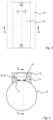
- the device 50 for capacitively measuring the powder level is shown in different views.
- the filling tube 28 has a recess 52 in which a holding section 54 made of an electrically non-conductive material, for example a plastic such as POM, is arranged.
- the holding section 54 carries a first measuring electrode 56 which extends in the axial direction of the filling tube 28 and parallel second and third measuring electrodes 58, 60 arranged in relation to the first measuring electrode 56, each of which extends parallel to and over approximately 10% of the length of the first measuring electrode 56.
- the second measuring electrode 58 is arranged in the area of the lower end of the first measuring electrode 56 and the third measuring electrode 60 in the area of the upper end of the first measuring electrode 56, as in particular in Figure 5 to recognize.
- the holding section 54 and with it the measuring electrodes 56, 58 and 60 are also covered on their side facing away from the filling tube 28 by an electrically non-conductive protective shield 62, which is at ground potential.
- the protective shield 62 is not shown for illustrative purposes.
- the filling pipe 28 is also at ground potential in the example shown.
- the filling tube 28 and the protective shield 62 can be made of a metal, for example.
- the filling tube 28 can be made of stainless steel and the protective shield 62 can be made of aluminum.
- the filling tube 28 forms a reference electrode for the measuring electrodes 56, 58 and 60.
- the measuring electrodes 56, 58 and 60 thus form three electrical capacitors with the filling tube 28 as a reference electrode, so that between the measuring electrodes 56, 58 and 60 and the reference electrode 28 can each form an electric field.
- the second measuring electrode 58 can be completely covered at any time with powder material located in the filling tube 28, while the third measuring electrode 60 can be located above the level of the powder material in the filling tube 28.
- the first measuring electrode 56 forms a measuring area for measuring the powder level in the filling tube 28.
- an electric field is formed between the measuring electrodes 56, 58 and 60 and the filling tube 28 serving as a reference electrode, controlled by the evaluation and control device 48, and the capacitance of the capacitors formed is measured, again by the evaluation and Control device 48.
- the evaluation and evaluation are based on the capacity measurement Control device 48 on the powder level in the filling tube 28.
- External interference can be largely minimized by the protective shield 62 at ground potential.
- the second and third measuring electrodes 58, 60 can be used to eliminate influences on the measurement result resulting from changes in the powder material or properties of the filling tube 28.
Landscapes
- Engineering & Computer Science (AREA)
- Physics & Mathematics (AREA)
- Mechanical Engineering (AREA)
- Power Engineering (AREA)
- General Physics & Mathematics (AREA)
- Chemical & Material Sciences (AREA)
- Fluid Mechanics (AREA)
- Thermal Sciences (AREA)
- Electromagnetism (AREA)
- Health & Medical Sciences (AREA)
- Immunology (AREA)
- Pathology (AREA)
- General Health & Medical Sciences (AREA)
- Biochemistry (AREA)
- Analytical Chemistry (AREA)
- Life Sciences & Earth Sciences (AREA)
- Electrochemistry (AREA)
- Chemical Kinetics & Catalysis (AREA)
- Measurement Of Levels Of Liquids Or Fluent Solid Materials (AREA)
Claims (14)
- Dispositif pour la mesure capacitive du niveau de remplissage de poudre dans un dispositif de remplissage (22) pour le remplissage de cavités (12) d'un disque porte-matrices (10) d'une presse rotative avec un matériau en poudre devant être comprimé dans la presse rotative, comprenant un tube de remplissage (28) du dispositif de remplissage (22), une première électrode de mesure (56) étant disposé sur le tube de remplissage (28), laquelle forme un premier condensateur électrique avec une électrode de référence (28), de telle sorte qu'un champ électrique peut être formé entre la première électrode de mesure (56) et l'électrode de référence (28), et la première électrode de mesure (56) étant couverte par un blindage de protection (62) électriquement conducteur sur son côté opposé au tube de remplissage (28), le blindage de protection (62) étant au potentiel terrestre, caractérisé en ce que la première électrode de mesure (56) est disposée dans une section de maintien (54) électriquement non conductrice, et en ce que la section de maintien (54) est disposée sur le tube de remplissage (28), dans un évidement (52) du tube de remplissage (28).
- Dispositif selon la revendication 1, caractérisé en ce qu'une section de tube de remplissage du dispositif de remplissage (22) électriquement conductrice se trouvant en amont et/ou en aval du tube de remplissage (28) muni de la première électrode de mesure (56) est également au potentiel terrestre.
- Procédé selon l'une des revendications précédentes, caractérisé en ce que l'électrode de référence (28) aussi est au potentiel terrestre.
- Procédé selon l'une des revendications précédentes, caractérisé en ce que le tube de remplissage (28) muni de la première électrode de mesure (56) aussi est au potentiel terrestre.
- Dispositif selon l'une des revendications 1 à 4, caractérisé en ce que l'électrode de référence est également disposée sur le tube de remplissage (28) muni de la première électrode de mesure (56).
- Dispositif selon l'une des revendications 1 à 4, caractérisé en ce que l'électrode de référence (28) est formée par le tube de remplissage (28) muni de la première électrode de mesure (56).
- Dispositif selon l'une des revendications précédentes, caractérisé en ce qu'une deuxième électrode de mesure (58) est en outre disposée sur le tube de remplissage (28), la deuxième électrode de mesure (58) et l'électrode de référence (28) formant un deuxième condensateur électrique, de sorte qu'un champ électrique peut être généré entre la deuxième électrode de mesure (58) et l'électrode de référence (28), et la plage de mesure de la deuxième électrode de mesure (58) étant sélectionnée de telle sorte qu'elle entièrement recouverte par du matériau en poudre se trouvant dans le tube de remplissage (28), pendant le fonctionnement de la presse rotative.
- Dispositif selon l'une des revendications précédentes, caractérisé en ce qu'une troisième électrode de mesure (60) est en outre disposée sur le tube de remplissage (28), la troisième électrode de mesure (60) et l'électrode de référence (28) formant un troisième condensateur électrique, de sorte qu'un champ électrique peut être généré entre la troisième électrode de mesure (60) et l'électrode de référence (28), et la plage de mesure de la troisième électrode de mesure (60) étant sélectionnée de telle sorte qu'elle se trouve au-dessus du niveau de remplissage du matériau en poudre dans le tube de remplissage (28), pendant le fonctionnement de la presse rotative.
- Dispositif selon l'une des revendications 7 ou 8, caractérisé en ce que la deuxième et/ou la troisième électrode de mesure (58, 60) aussi sont recouvertes par le blindage de protection (62) électriquement conducteur sur leur côté opposé au tube de remplissage (28).
- Dispositif selon l'une des revendications 7 à 9, caractérisé en ce que la deuxième et/ou la troisième électrodes (58, 60) sont disposées dans le section de maintien (54) électriquement non conductrice.
- Dispositif selon l'une des revendications précédentes, caractérisé en ce que le blindage de protection (62) forme un blindage de protection (62) actif, lequel est excité avec le même potentiel que la première électrode de mesure (56) et/ou la deuxième électrode de mesure (58) et/ou la troisième électrode de mesure (60), lors d'une mesure du niveau de remplissage.
- Dispositif selon l'une des revendications précédentes, caractérisé en ce qu'un dispositif de commande et d'analyse (48) est en outre prévu, lequel excite les électrodes de mesure et de référence pendant le fonctionnement de la presse rotative et détermine le niveau de remplissage du matériau en poudre dans le tube de remplissage (28), à l'aide des données de mesure des électrodes de mesure et de référence (28, 56, 58, 60).
- Dispositif selon l'une des revendications précédentes, caractérisé en ce que les électrodes de mesure et/ou de référence (28, 56, 58, 60) sont disposées sur des cartes de circuit imprimé PCB essentiellement non flexibles.
- Presse rotative, comprenant un rotor rotatif grâce à un entraînement rotatif, le rotor présentant un guide de poinçon supérieur (13) pour poinçons supérieurs (14) de la presse rotative et un guide de poinçon inférieur (15) pour poinçons inférieurs (16) de la presse rotative ainsi qu'un disque porte-matrices (10) disposée entre les guides de poinçons (13, 15), les poinçons (14, 16) interagissant avec des cavités (12) du disque porte-matrices (10), comprenant en outre un dispositif de remplissage (22), à travers lequel du matériau en poudre devant être comprimé est versé dans les cavités (12) du disque porte-matrices (10), le dispositif de remplissage (22) comprenant un tube de remplissage (28), comprenant en outre au moins un dispositif de pressage (30) supérieur et au moins un dispositif de pressage (30) inférieur, lesquels interagissent avec les poinçons supérieurs (14) et avec les poinçons inférieurs (16) pendant le fonctionnement, pour la compression du matériau en poudre dans les cavités (12) du disque porte-matrices (10), comprenant en outre un dispositif d'éjection (40), dans lequel les pièces pressées produites dans les cavités (12) sont éjectées, caractérisée par un dispositif (50) pour la mesure capacitive du niveau de remplissage de poudre dans le dispositif de remplissage (22) selon l'une des revendications précédentes.
Applications Claiming Priority (1)
| Application Number | Priority Date | Filing Date | Title |
|---|---|---|---|
| DE102019129793.1A DE102019129793A1 (de) | 2019-11-05 | 2019-11-05 | Vorrichtung zum kapazitiven Messen des Pulverfüllstands in einer Fülleinrichtung einer Rundläuferpresse |
Publications (2)
| Publication Number | Publication Date |
|---|---|
| EP3819112A1 EP3819112A1 (fr) | 2021-05-12 |
| EP3819112B1 true EP3819112B1 (fr) | 2023-09-13 |
Family
ID=72852451
Family Applications (1)
| Application Number | Title | Priority Date | Filing Date |
|---|---|---|---|
| EP20201517.8A Active EP3819112B1 (fr) | 2019-11-05 | 2020-10-13 | Dispositif de mesure capacitive du niveau de remplissage de poudre dans un dispositif de remplissage d'une presse rotative |
Country Status (6)
| Country | Link |
|---|---|
| US (1) | US12181325B2 (fr) |
| EP (1) | EP3819112B1 (fr) |
| JP (1) | JP7075980B2 (fr) |
| CN (1) | CN112782244B (fr) |
| DE (1) | DE102019129793A1 (fr) |
| PL (1) | PL3819112T3 (fr) |
Families Citing this family (1)
| Publication number | Priority date | Publication date | Assignee | Title |
|---|---|---|---|---|
| CN113547749A (zh) * | 2021-07-26 | 2021-10-26 | 重庆凯丰医疗器械有限公司 | 具有除杂功能的tdp灸疗贴的粉料装填装置 |
Family Cites Families (19)
| Publication number | Priority date | Publication date | Assignee | Title |
|---|---|---|---|---|
| GB1544416A (en) * | 1975-10-08 | 1979-04-19 | Molins Ltd | Apparatus for feeding tobacco or similar particulate material in a uniform stream |
| JPS61204076A (ja) | 1985-03-07 | 1986-09-10 | 三明電機株式会社 | 掃除装置 |
| JPH0340479Y2 (fr) * | 1986-12-25 | 1991-08-26 | ||
| US5459406A (en) * | 1994-07-01 | 1995-10-17 | Cornell Research Foundation, Inc. | Guarded capacitance probes for measuring particle concentration and flow |
| US6490920B1 (en) * | 1997-08-25 | 2002-12-10 | Millennium Sensors Ltd. | Compensated capacitive liquid level sensor |
| US6539797B2 (en) * | 2001-06-25 | 2003-04-01 | Becs Technology, Inc. | Auto-compensating capacitive level sensor |
| JP4104527B2 (ja) * | 2003-10-21 | 2008-06-18 | 株式会社テルモ工業 | レベルセンサ |
| EP1961575B1 (fr) * | 2007-02-23 | 2011-06-08 | SII Printek Inc | Capteur de détection de la quantité restante et imprimante à jet d'encre l'utilisant |
| JP5044336B2 (ja) * | 2007-09-07 | 2012-10-10 | 山本電機工業株式会社 | レベルゲージセンサ |
| CH702942A1 (de) * | 2010-03-31 | 2011-10-14 | Tecan Trading Ag | Kapazitives Messverfahren und Vorrichtung zur Füllstandsdetektion und entsprechend ausgestattetes Laborgerät. |
| DE102010025118A1 (de) * | 2010-06-25 | 2011-12-29 | Siemens Healthcare Diagnostics Products Gmbh | Berührungslose Füllstandsmessung von Flüssigkeiten |
| WO2012102701A1 (fr) * | 2011-01-25 | 2012-08-02 | Hewlett-Packard Development Company, L.P. | Détection capacitive du niveau d'un fluide |
| US8590375B2 (en) * | 2011-03-22 | 2013-11-26 | Rochester Gauges, Inc. | Self-calibrating capacitive liquid level sensor assembly and method |
| KR101221619B1 (ko) * | 2012-07-20 | 2013-01-14 | 주식회사 래더트론 | 정전용량을 이용한 파이프 내부에 고착된 파우더 두께 검사 장치 |
| DE102014006695A1 (de) * | 2013-05-13 | 2014-11-13 | Hella Kgaa Hueck & Co. | Füllstandssensor zur Messung des Füllstands und Verfahren zur Bestimmung des Füllstands einer Flüssigkeit |
| EP2982400A1 (fr) * | 2014-08-07 | 2016-02-10 | Valtronic Technologies (Holding) SA | Dispositif pour la fixation à un dispositif portable d'injection de liquide |
| DE102016113724B4 (de) * | 2016-07-26 | 2019-01-17 | Fette Compacting Gmbh | Stempel für eine Rundläuferpresse |
| DE102017207162A1 (de) * | 2017-04-28 | 2018-10-31 | Robert Bosch Gmbh | Vorrichtung zum Komprimieren eines Produkts |
| CN207456560U (zh) * | 2017-08-22 | 2018-06-05 | 深圳瑞湖科技有限公司 | 一种电容式水位传感器和水位检测装置 |
-
2019
- 2019-11-05 DE DE102019129793.1A patent/DE102019129793A1/de not_active Withdrawn
-
2020
- 2020-10-13 EP EP20201517.8A patent/EP3819112B1/fr active Active
- 2020-10-13 PL PL20201517.8T patent/PL3819112T3/pl unknown
- 2020-10-27 JP JP2020179776A patent/JP7075980B2/ja active Active
- 2020-11-04 CN CN202011214109.7A patent/CN112782244B/zh active Active
- 2020-11-05 US US17/089,824 patent/US12181325B2/en active Active
Also Published As
| Publication number | Publication date |
|---|---|
| JP7075980B2 (ja) | 2022-05-26 |
| EP3819112A1 (fr) | 2021-05-12 |
| CN112782244A (zh) | 2021-05-11 |
| DE102019129793A1 (de) | 2021-05-06 |
| CN112782244B (zh) | 2024-12-31 |
| US12181325B2 (en) | 2024-12-31 |
| JP2021074778A (ja) | 2021-05-20 |
| PL3819112T3 (pl) | 2024-03-04 |
| US20210131853A1 (en) | 2021-05-06 |
Similar Documents
| Publication | Publication Date | Title |
|---|---|---|
| DE19949985C2 (de) | Kapazitiver Sensor zur Detektion des Füllstandes eines Mediums in einem Behälter | |
| EP2872102B1 (fr) | Dispositif de pesée de capsules, machine de remplissage de capsules et procédé pour la pesée d'une capsule | |
| DE102004040441A1 (de) | Vorrichtung und Verfahren zur Bestimmung des Füllstandes einer Ampulle | |
| EP2707208B1 (fr) | Dispositif et procédé d'étalonnage et d'ajustement d'un dispositif de mesure d'une presse à comprimés | |
| EP0924518B1 (fr) | Appareil pour la mesure de caractéristiques d'un produit textile | |
| EP2581313A1 (fr) | Dispositif de contrôle de tablettes mobiles | |
| DE2755517A1 (de) | Kapazitive vorrichtung zur messung eines fluessigkeitspegels | |
| EP2198241A1 (fr) | Dispositif détecteur pour détermination capacitive de distance | |
| DE3105020A1 (de) | Vorrichtung zum aufbringen eines fluids, insbesondere von lacken auf bedruckte bogen oder bahnen | |
| EP3819112B1 (fr) | Dispositif de mesure capacitive du niveau de remplissage de poudre dans un dispositif de remplissage d'une presse rotative | |
| EP4045708A1 (fr) | Bande d'étanchéité et dispositif d'étanchéité | |
| DE102016114586B4 (de) | Pulverzuführvorrichtung | |
| CH648679A5 (de) | Kapazitiver muenzpruefer. | |
| EP4079500B1 (fr) | Système de traitement continu des produits pulvérulents | |
| DE10004146C2 (de) | Anordnung zur Vermessung der Ausbreitung eines Matrixmaterials in elektrisch leitfähigen Verstärkungsstrukturen | |
| AT405884B (de) | Detektor zur messung der elektrolytischen leitfähigkeit | |
| EP1164380A2 (fr) | Circuit pout détecter des changements de capacitance | |
| DE4306061C2 (de) | Vorrichtung zur Detektion des Füllstandes eines kapillaren Überlaufkanals | |
| DE102011083830A1 (de) | Verfahren zur Dickenmessung eines bahnförmigen Materials und Messgerät nach einem solchen Verfahren | |
| DE102022125376B4 (de) | Messrolle zum Messen eines Bandzugs und Verfahren | |
| DE102024109411B3 (de) | Rundläufertablettenpresse | |
| DE10341249B4 (de) | Seitenplatte zum Abdichten eines zwischen den Gießwalzen einer Zweiwalzengießvorrichtung gebildeten Gießspalts, Zweiwalzengießvorrichtung und Verfahren zu ihrem Betrieb | |
| EP4575523A1 (fr) | Broyeur à champ électrique pour détecter un champ électrique d'un conducteur ainsi que procédé de détection d'un champ électrique | |
| WO2024132411A1 (fr) | Appareil et procédé de mesure capacitive de niveau de remplissage | |
| DE20004245U1 (de) | Druckmeß-Vorrichtung |
Legal Events
| Date | Code | Title | Description |
|---|---|---|---|
| PUAI | Public reference made under article 153(3) epc to a published international application that has entered the european phase |
Free format text: ORIGINAL CODE: 0009012 |
|
| STAA | Information on the status of an ep patent application or granted ep patent |
Free format text: STATUS: THE APPLICATION HAS BEEN PUBLISHED |
|
| AK | Designated contracting states |
Kind code of ref document: A1 Designated state(s): AL AT BE BG CH CY CZ DE DK EE ES FI FR GB GR HR HU IE IS IT LI LT LU LV MC MK MT NL NO PL PT RO RS SE SI SK SM TR |
|
| RIN1 | Information on inventor provided before grant (corrected) |
Inventor name: EVERS, ALEXANDER Inventor name: WALTER, NICOLAS Inventor name: KOLBE, SVEN |
|
| STAA | Information on the status of an ep patent application or granted ep patent |
Free format text: STATUS: REQUEST FOR EXAMINATION WAS MADE |
|
| 17P | Request for examination filed |
Effective date: 20211111 |
|
| RBV | Designated contracting states (corrected) |
Designated state(s): AL AT BE BG CH CY CZ DE DK EE ES FI FR GB GR HR HU IE IS IT LI LT LU LV MC MK MT NL NO PL PT RO RS SE SI SK SM TR |
|
| GRAP | Despatch of communication of intention to grant a patent |
Free format text: ORIGINAL CODE: EPIDOSNIGR1 |
|
| STAA | Information on the status of an ep patent application or granted ep patent |
Free format text: STATUS: GRANT OF PATENT IS INTENDED |
|
| RIC1 | Information provided on ipc code assigned before grant |
Ipc: B30B 11/08 20060101ALN20230424BHEP Ipc: G01F 23/263 20220101ALI20230424BHEP Ipc: G01B 7/06 20060101ALI20230424BHEP Ipc: B30B 15/30 20060101AFI20230424BHEP |
|
| INTG | Intention to grant announced |
Effective date: 20230510 |
|
| P01 | Opt-out of the competence of the unified patent court (upc) registered |
Effective date: 20230530 |
|
| GRAS | Grant fee paid |
Free format text: ORIGINAL CODE: EPIDOSNIGR3 |
|
| GRAA | (expected) grant |
Free format text: ORIGINAL CODE: 0009210 |
|
| STAA | Information on the status of an ep patent application or granted ep patent |
Free format text: STATUS: THE PATENT HAS BEEN GRANTED |
|
| AK | Designated contracting states |
Kind code of ref document: B1 Designated state(s): AL AT BE BG CH CY CZ DE DK EE ES FI FR GB GR HR HU IE IS IT LI LT LU LV MC MK MT NL NO PL PT RO RS SE SI SK SM TR |
|
| REG | Reference to a national code |
Ref country code: CH Ref legal event code: EP |
|
| REG | Reference to a national code |
Ref country code: DE Ref legal event code: R096 Ref document number: 502020005213 Country of ref document: DE |
|
| REG | Reference to a national code |
Ref country code: IE Ref legal event code: FG4D Free format text: LANGUAGE OF EP DOCUMENT: GERMAN |
|
| REG | Reference to a national code |
Ref country code: LT Ref legal event code: MG9D |
|
| REG | Reference to a national code |
Ref country code: NL Ref legal event code: MP Effective date: 20230913 |
|
| PG25 | Lapsed in a contracting state [announced via postgrant information from national office to epo] |
Ref country code: GR Free format text: LAPSE BECAUSE OF FAILURE TO SUBMIT A TRANSLATION OF THE DESCRIPTION OR TO PAY THE FEE WITHIN THE PRESCRIBED TIME-LIMIT Effective date: 20231214 |
|
| PG25 | Lapsed in a contracting state [announced via postgrant information from national office to epo] |
Ref country code: SE Free format text: LAPSE BECAUSE OF FAILURE TO SUBMIT A TRANSLATION OF THE DESCRIPTION OR TO PAY THE FEE WITHIN THE PRESCRIBED TIME-LIMIT Effective date: 20230913 Ref country code: RS Free format text: LAPSE BECAUSE OF FAILURE TO SUBMIT A TRANSLATION OF THE DESCRIPTION OR TO PAY THE FEE WITHIN THE PRESCRIBED TIME-LIMIT Effective date: 20230913 Ref country code: NO Free format text: LAPSE BECAUSE OF FAILURE TO SUBMIT A TRANSLATION OF THE DESCRIPTION OR TO PAY THE FEE WITHIN THE PRESCRIBED TIME-LIMIT Effective date: 20231213 Ref country code: LV Free format text: LAPSE BECAUSE OF FAILURE TO SUBMIT A TRANSLATION OF THE DESCRIPTION OR TO PAY THE FEE WITHIN THE PRESCRIBED TIME-LIMIT Effective date: 20230913 Ref country code: LT Free format text: LAPSE BECAUSE OF FAILURE TO SUBMIT A TRANSLATION OF THE DESCRIPTION OR TO PAY THE FEE WITHIN THE PRESCRIBED TIME-LIMIT Effective date: 20230913 Ref country code: HR Free format text: LAPSE BECAUSE OF FAILURE TO SUBMIT A TRANSLATION OF THE DESCRIPTION OR TO PAY THE FEE WITHIN THE PRESCRIBED TIME-LIMIT Effective date: 20230913 Ref country code: GR Free format text: LAPSE BECAUSE OF FAILURE TO SUBMIT A TRANSLATION OF THE DESCRIPTION OR TO PAY THE FEE WITHIN THE PRESCRIBED TIME-LIMIT Effective date: 20231214 Ref country code: FI Free format text: LAPSE BECAUSE OF FAILURE TO SUBMIT A TRANSLATION OF THE DESCRIPTION OR TO PAY THE FEE WITHIN THE PRESCRIBED TIME-LIMIT Effective date: 20230913 |
|
| PG25 | Lapsed in a contracting state [announced via postgrant information from national office to epo] |
Ref country code: NL Free format text: LAPSE BECAUSE OF FAILURE TO SUBMIT A TRANSLATION OF THE DESCRIPTION OR TO PAY THE FEE WITHIN THE PRESCRIBED TIME-LIMIT Effective date: 20230913 |
|
| PG25 | Lapsed in a contracting state [announced via postgrant information from national office to epo] |
Ref country code: IS Free format text: LAPSE BECAUSE OF FAILURE TO SUBMIT A TRANSLATION OF THE DESCRIPTION OR TO PAY THE FEE WITHIN THE PRESCRIBED TIME-LIMIT Effective date: 20240113 |
|
| PG25 | Lapsed in a contracting state [announced via postgrant information from national office to epo] |
Ref country code: ES Free format text: LAPSE BECAUSE OF FAILURE TO SUBMIT A TRANSLATION OF THE DESCRIPTION OR TO PAY THE FEE WITHIN THE PRESCRIBED TIME-LIMIT Effective date: 20230913 |
|
| PG25 | Lapsed in a contracting state [announced via postgrant information from national office to epo] |
Ref country code: SM Free format text: LAPSE BECAUSE OF FAILURE TO SUBMIT A TRANSLATION OF THE DESCRIPTION OR TO PAY THE FEE WITHIN THE PRESCRIBED TIME-LIMIT Effective date: 20230913 Ref country code: RO Free format text: LAPSE BECAUSE OF FAILURE TO SUBMIT A TRANSLATION OF THE DESCRIPTION OR TO PAY THE FEE WITHIN THE PRESCRIBED TIME-LIMIT Effective date: 20230913 Ref country code: IT Free format text: LAPSE BECAUSE OF NON-PAYMENT OF DUE FEES Effective date: 20231013 Ref country code: IS Free format text: LAPSE BECAUSE OF FAILURE TO SUBMIT A TRANSLATION OF THE DESCRIPTION OR TO PAY THE FEE WITHIN THE PRESCRIBED TIME-LIMIT Effective date: 20240113 Ref country code: ES Free format text: LAPSE BECAUSE OF FAILURE TO SUBMIT A TRANSLATION OF THE DESCRIPTION OR TO PAY THE FEE WITHIN THE PRESCRIBED TIME-LIMIT Effective date: 20230913 Ref country code: EE Free format text: LAPSE BECAUSE OF FAILURE TO SUBMIT A TRANSLATION OF THE DESCRIPTION OR TO PAY THE FEE WITHIN THE PRESCRIBED TIME-LIMIT Effective date: 20230913 Ref country code: CZ Free format text: LAPSE BECAUSE OF FAILURE TO SUBMIT A TRANSLATION OF THE DESCRIPTION OR TO PAY THE FEE WITHIN THE PRESCRIBED TIME-LIMIT Effective date: 20230913 Ref country code: PT Free format text: LAPSE BECAUSE OF FAILURE TO SUBMIT A TRANSLATION OF THE DESCRIPTION OR TO PAY THE FEE WITHIN THE PRESCRIBED TIME-LIMIT Effective date: 20240115 Ref country code: SK Free format text: LAPSE BECAUSE OF FAILURE TO SUBMIT A TRANSLATION OF THE DESCRIPTION OR TO PAY THE FEE WITHIN THE PRESCRIBED TIME-LIMIT Effective date: 20230913 |
|
| REG | Reference to a national code |
Ref country code: DE Ref legal event code: R097 Ref document number: 502020005213 Country of ref document: DE |
|
| PG25 | Lapsed in a contracting state [announced via postgrant information from national office to epo] |
Ref country code: LU Free format text: LAPSE BECAUSE OF NON-PAYMENT OF DUE FEES Effective date: 20231013 |
|
| PG25 | Lapsed in a contracting state [announced via postgrant information from national office to epo] |
Ref country code: LU Free format text: LAPSE BECAUSE OF NON-PAYMENT OF DUE FEES Effective date: 20231013 |
|
| PG25 | Lapsed in a contracting state [announced via postgrant information from national office to epo] |
Ref country code: MC Free format text: LAPSE BECAUSE OF FAILURE TO SUBMIT A TRANSLATION OF THE DESCRIPTION OR TO PAY THE FEE WITHIN THE PRESCRIBED TIME-LIMIT Effective date: 20230913 |
|
| PG25 | Lapsed in a contracting state [announced via postgrant information from national office to epo] |
Ref country code: DK Free format text: LAPSE BECAUSE OF FAILURE TO SUBMIT A TRANSLATION OF THE DESCRIPTION OR TO PAY THE FEE WITHIN THE PRESCRIBED TIME-LIMIT Effective date: 20230913 |
|
| PLBE | No opposition filed within time limit |
Free format text: ORIGINAL CODE: 0009261 |
|
| STAA | Information on the status of an ep patent application or granted ep patent |
Free format text: STATUS: NO OPPOSITION FILED WITHIN TIME LIMIT |
|
| PG25 | Lapsed in a contracting state [announced via postgrant information from national office to epo] |
Ref country code: MC Free format text: LAPSE BECAUSE OF FAILURE TO SUBMIT A TRANSLATION OF THE DESCRIPTION OR TO PAY THE FEE WITHIN THE PRESCRIBED TIME-LIMIT Effective date: 20230913 Ref country code: DK Free format text: LAPSE BECAUSE OF FAILURE TO SUBMIT A TRANSLATION OF THE DESCRIPTION OR TO PAY THE FEE WITHIN THE PRESCRIBED TIME-LIMIT Effective date: 20230913 |
|
| 26N | No opposition filed |
Effective date: 20240614 |
|
| PG25 | Lapsed in a contracting state [announced via postgrant information from national office to epo] |
Ref country code: IE Free format text: LAPSE BECAUSE OF NON-PAYMENT OF DUE FEES Effective date: 20231013 |
|
| PG25 | Lapsed in a contracting state [announced via postgrant information from national office to epo] |
Ref country code: SI Free format text: LAPSE BECAUSE OF FAILURE TO SUBMIT A TRANSLATION OF THE DESCRIPTION OR TO PAY THE FEE WITHIN THE PRESCRIBED TIME-LIMIT Effective date: 20230913 |
|
| PG25 | Lapsed in a contracting state [announced via postgrant information from national office to epo] |
Ref country code: SI Free format text: LAPSE BECAUSE OF FAILURE TO SUBMIT A TRANSLATION OF THE DESCRIPTION OR TO PAY THE FEE WITHIN THE PRESCRIBED TIME-LIMIT Effective date: 20230913 Ref country code: IE Free format text: LAPSE BECAUSE OF NON-PAYMENT OF DUE FEES Effective date: 20231013 |
|
| PG25 | Lapsed in a contracting state [announced via postgrant information from national office to epo] |
Ref country code: BG Free format text: LAPSE BECAUSE OF FAILURE TO SUBMIT A TRANSLATION OF THE DESCRIPTION OR TO PAY THE FEE WITHIN THE PRESCRIBED TIME-LIMIT Effective date: 20230913 |
|
| PG25 | Lapsed in a contracting state [announced via postgrant information from national office to epo] |
Ref country code: BG Free format text: LAPSE BECAUSE OF FAILURE TO SUBMIT A TRANSLATION OF THE DESCRIPTION OR TO PAY THE FEE WITHIN THE PRESCRIBED TIME-LIMIT Effective date: 20230913 |
|
| PG25 | Lapsed in a contracting state [announced via postgrant information from national office to epo] |
Ref country code: IT Free format text: LAPSE BECAUSE OF NON-PAYMENT OF DUE FEES Effective date: 20231013 |
|
| PGRI | Patent reinstated in contracting state [announced from national office to epo] |
Ref country code: IT Effective date: 20231031 |
|
| PG25 | Lapsed in a contracting state [announced via postgrant information from national office to epo] |
Ref country code: CY Free format text: LAPSE BECAUSE OF FAILURE TO SUBMIT A TRANSLATION OF THE DESCRIPTION OR TO PAY THE FEE WITHIN THE PRESCRIBED TIME-LIMIT; INVALID AB INITIO Effective date: 20201013 |
|
| PG25 | Lapsed in a contracting state [announced via postgrant information from national office to epo] |
Ref country code: HU Free format text: LAPSE BECAUSE OF FAILURE TO SUBMIT A TRANSLATION OF THE DESCRIPTION OR TO PAY THE FEE WITHIN THE PRESCRIBED TIME-LIMIT; INVALID AB INITIO Effective date: 20201013 |
|
| PGFP | Annual fee paid to national office [announced via postgrant information from national office to epo] |
Ref country code: PL Payment date: 20250917 Year of fee payment: 6 |
|
| REG | Reference to a national code |
Ref country code: CH Ref legal event code: U11 Free format text: ST27 STATUS EVENT CODE: U-0-0-U10-U11 (AS PROVIDED BY THE NATIONAL OFFICE) Effective date: 20251101 |
|
| PG25 | Lapsed in a contracting state [announced via postgrant information from national office to epo] |
Ref country code: TR Free format text: LAPSE BECAUSE OF FAILURE TO SUBMIT A TRANSLATION OF THE DESCRIPTION OR TO PAY THE FEE WITHIN THE PRESCRIBED TIME-LIMIT Effective date: 20230913 |
|
| PGFP | Annual fee paid to national office [announced via postgrant information from national office to epo] |
Ref country code: DE Payment date: 20251211 Year of fee payment: 6 |
|
| PGFP | Annual fee paid to national office [announced via postgrant information from national office to epo] |
Ref country code: GB Payment date: 20251024 Year of fee payment: 6 |
|
| PGFP | Annual fee paid to national office [announced via postgrant information from national office to epo] |
Ref country code: AT Payment date: 20260113 Year of fee payment: 5 |
|
| PGFP | Annual fee paid to national office [announced via postgrant information from national office to epo] |
Ref country code: IT Payment date: 20251031 Year of fee payment: 6 |
|
| PGFP | Annual fee paid to national office [announced via postgrant information from national office to epo] |
Ref country code: FR Payment date: 20251029 Year of fee payment: 6 |
|
| PGFP | Annual fee paid to national office [announced via postgrant information from national office to epo] |
Ref country code: BE Payment date: 20251022 Year of fee payment: 6 |
|
| PGFP | Annual fee paid to national office [announced via postgrant information from national office to epo] |
Ref country code: CH Payment date: 20251101 Year of fee payment: 6 |