EP3819924A1 - Fibre magnétique hybride et son procédé de fabrication - Google Patents
Fibre magnétique hybride et son procédé de fabrication Download PDFInfo
- Publication number
- EP3819924A1 EP3819924A1 EP19830775.3A EP19830775A EP3819924A1 EP 3819924 A1 EP3819924 A1 EP 3819924A1 EP 19830775 A EP19830775 A EP 19830775A EP 3819924 A1 EP3819924 A1 EP 3819924A1
- Authority
- EP
- European Patent Office
- Prior art keywords
- magnetic
- fiber
- hybrid
- hybrid magnetic
- rare
- Prior art date
- Legal status (The legal status is an assumption and is not a legal conclusion. Google has not performed a legal analysis and makes no representation as to the accuracy of the status listed.)
- Withdrawn
Links
Images












Classifications
-
- H—ELECTRICITY
- H01—ELECTRIC ELEMENTS
- H01F—MAGNETS; INDUCTANCES; TRANSFORMERS; SELECTION OF MATERIALS FOR THEIR MAGNETIC PROPERTIES
- H01F41/00—Apparatus or processes specially adapted for manufacturing or assembling magnets, inductances or transformers; Apparatus or processes specially adapted for manufacturing materials characterised by their magnetic properties
- H01F41/02—Apparatus or processes specially adapted for manufacturing or assembling magnets, inductances or transformers; Apparatus or processes specially adapted for manufacturing materials characterised by their magnetic properties for manufacturing cores, coils, or magnets
- H01F41/0253—Apparatus or processes specially adapted for manufacturing or assembling magnets, inductances or transformers; Apparatus or processes specially adapted for manufacturing materials characterised by their magnetic properties for manufacturing cores, coils, or magnets for manufacturing permanent magnets
- H01F41/0273—Imparting anisotropy
-
- D—TEXTILES; PAPER
- D01—NATURAL OR MAN-MADE THREADS OR FIBRES; SPINNING
- D01D—MECHANICAL METHODS OR APPARATUS IN THE MANUFACTURE OF ARTIFICIAL FILAMENTS, THREADS, FIBRES, BRISTLES OR RIBBONS
- D01D5/00—Formation of filaments, threads, or the like
-
- D—TEXTILES; PAPER
- D01—NATURAL OR MAN-MADE THREADS OR FIBRES; SPINNING
- D01F—CHEMICAL FEATURES IN THE MANUFACTURE OF ARTIFICIAL FILAMENTS, THREADS, FIBRES, BRISTLES OR RIBBONS; APPARATUS SPECIALLY ADAPTED FOR THE MANUFACTURE OF CARBON FILAMENTS
- D01F1/00—General methods for the manufacture of artificial filaments or the like
- D01F1/02—Addition of substances to the spinning solution or to the melt
- D01F1/10—Other agents for modifying properties
-
- H—ELECTRICITY
- H01—ELECTRIC ELEMENTS
- H01F—MAGNETS; INDUCTANCES; TRANSFORMERS; SELECTION OF MATERIALS FOR THEIR MAGNETIC PROPERTIES
- H01F1/00—Magnets or magnetic bodies characterised by the magnetic materials therefor; Selection of materials for their magnetic properties
- H01F1/0036—Magnets or magnetic bodies characterised by the magnetic materials therefor; Selection of materials for their magnetic properties showing low dimensional magnetism, i.e. spin rearrangements due to a restriction of dimensions, e.g. showing giant magnetoresistivity
- H01F1/0072—Magnets or magnetic bodies characterised by the magnetic materials therefor; Selection of materials for their magnetic properties showing low dimensional magnetism, i.e. spin rearrangements due to a restriction of dimensions, e.g. showing giant magnetoresistivity one dimensional, i.e. linear or dendritic nanostructures
-
- H—ELECTRICITY
- H01—ELECTRIC ELEMENTS
- H01F—MAGNETS; INDUCTANCES; TRANSFORMERS; SELECTION OF MATERIALS FOR THEIR MAGNETIC PROPERTIES
- H01F1/00—Magnets or magnetic bodies characterised by the magnetic materials therefor; Selection of materials for their magnetic properties
- H01F1/01—Magnets or magnetic bodies characterised by the magnetic materials therefor; Selection of materials for their magnetic properties of inorganic materials
- H01F1/03—Magnets or magnetic bodies characterised by the magnetic materials therefor; Selection of materials for their magnetic properties of inorganic materials characterised by their coercivity
- H01F1/032—Magnets or magnetic bodies characterised by the magnetic materials therefor; Selection of materials for their magnetic properties of inorganic materials characterised by their coercivity of hard-magnetic materials
- H01F1/04—Magnets or magnetic bodies characterised by the magnetic materials therefor; Selection of materials for their magnetic properties of inorganic materials characterised by their coercivity of hard-magnetic materials metals or alloys
- H01F1/047—Alloys characterised by their composition
- H01F1/053—Alloys characterised by their composition containing rare earth metals
- H01F1/055—Alloys characterised by their composition containing rare earth metals and magnetic transition metals, e.g. SmCo5
-
- H—ELECTRICITY
- H01—ELECTRIC ELEMENTS
- H01F—MAGNETS; INDUCTANCES; TRANSFORMERS; SELECTION OF MATERIALS FOR THEIR MAGNETIC PROPERTIES
- H01F1/00—Magnets or magnetic bodies characterised by the magnetic materials therefor; Selection of materials for their magnetic properties
- H01F1/01—Magnets or magnetic bodies characterised by the magnetic materials therefor; Selection of materials for their magnetic properties of inorganic materials
- H01F1/03—Magnets or magnetic bodies characterised by the magnetic materials therefor; Selection of materials for their magnetic properties of inorganic materials characterised by their coercivity
- H01F1/12—Magnets or magnetic bodies characterised by the magnetic materials therefor; Selection of materials for their magnetic properties of inorganic materials characterised by their coercivity of soft-magnetic materials
- H01F1/14—Magnets or magnetic bodies characterised by the magnetic materials therefor; Selection of materials for their magnetic properties of inorganic materials characterised by their coercivity of soft-magnetic materials metals or alloys
-
- H—ELECTRICITY
- H01—ELECTRIC ELEMENTS
- H01F—MAGNETS; INDUCTANCES; TRANSFORMERS; SELECTION OF MATERIALS FOR THEIR MAGNETIC PROPERTIES
- H01F1/00—Magnets or magnetic bodies characterised by the magnetic materials therefor; Selection of materials for their magnetic properties
- H01F1/01—Magnets or magnetic bodies characterised by the magnetic materials therefor; Selection of materials for their magnetic properties of inorganic materials
- H01F1/03—Magnets or magnetic bodies characterised by the magnetic materials therefor; Selection of materials for their magnetic properties of inorganic materials characterised by their coercivity
- H01F1/032—Magnets or magnetic bodies characterised by the magnetic materials therefor; Selection of materials for their magnetic properties of inorganic materials characterised by their coercivity of hard-magnetic materials
- H01F1/04—Magnets or magnetic bodies characterised by the magnetic materials therefor; Selection of materials for their magnetic properties of inorganic materials characterised by their coercivity of hard-magnetic materials metals or alloys
- H01F1/047—Alloys characterised by their composition
- H01F1/053—Alloys characterised by their composition containing rare earth metals
- H01F1/055—Alloys characterised by their composition containing rare earth metals and magnetic transition metals, e.g. SmCo5
- H01F1/0553—Alloys characterised by their composition containing rare earth metals and magnetic transition metals, e.g. SmCo5 obtained by reduction or by hydrogen decrepitation or embrittlement
-
- H—ELECTRICITY
- H01—ELECTRIC ELEMENTS
- H01F—MAGNETS; INDUCTANCES; TRANSFORMERS; SELECTION OF MATERIALS FOR THEIR MAGNETIC PROPERTIES
- H01F1/00—Magnets or magnetic bodies characterised by the magnetic materials therefor; Selection of materials for their magnetic properties
- H01F1/01—Magnets or magnetic bodies characterised by the magnetic materials therefor; Selection of materials for their magnetic properties of inorganic materials
- H01F1/03—Magnets or magnetic bodies characterised by the magnetic materials therefor; Selection of materials for their magnetic properties of inorganic materials characterised by their coercivity
- H01F1/032—Magnets or magnetic bodies characterised by the magnetic materials therefor; Selection of materials for their magnetic properties of inorganic materials characterised by their coercivity of hard-magnetic materials
- H01F1/04—Magnets or magnetic bodies characterised by the magnetic materials therefor; Selection of materials for their magnetic properties of inorganic materials characterised by their coercivity of hard-magnetic materials metals or alloys
- H01F1/047—Alloys characterised by their composition
- H01F1/053—Alloys characterised by their composition containing rare earth metals
- H01F1/055—Alloys characterised by their composition containing rare earth metals and magnetic transition metals, e.g. SmCo5
- H01F1/057—Alloys characterised by their composition containing rare earth metals and magnetic transition metals, e.g. SmCo5 and IIIa elements, e.g. Nd2Fe14B
- H01F1/0579—Alloys characterised by their composition containing rare earth metals and magnetic transition metals, e.g. SmCo5 and IIIa elements, e.g. Nd2Fe14B with exchange spin coupling between hard and soft nanophases, e.g. nanocomposite spring magnets
-
- H—ELECTRICITY
- H01—ELECTRIC ELEMENTS
- H01F—MAGNETS; INDUCTANCES; TRANSFORMERS; SELECTION OF MATERIALS FOR THEIR MAGNETIC PROPERTIES
- H01F1/00—Magnets or magnetic bodies characterised by the magnetic materials therefor; Selection of materials for their magnetic properties
- H01F1/01—Magnets or magnetic bodies characterised by the magnetic materials therefor; Selection of materials for their magnetic properties of inorganic materials
- H01F1/03—Magnets or magnetic bodies characterised by the magnetic materials therefor; Selection of materials for their magnetic properties of inorganic materials characterised by their coercivity
- H01F1/12—Magnets or magnetic bodies characterised by the magnetic materials therefor; Selection of materials for their magnetic properties of inorganic materials characterised by their coercivity of soft-magnetic materials
- H01F1/14—Magnets or magnetic bodies characterised by the magnetic materials therefor; Selection of materials for their magnetic properties of inorganic materials characterised by their coercivity of soft-magnetic materials metals or alloys
- H01F1/143—Magnets or magnetic bodies characterised by the magnetic materials therefor; Selection of materials for their magnetic properties of inorganic materials characterised by their coercivity of soft-magnetic materials metals or alloys in the form of wires
Definitions
- the present invention relates to a hybrid magnetic fiber and a method for preparing the same, and more specifically to a hybrid magnetic fiber including both a hard-magnetic property and a soft-magnetic property and a method for preparing the same.
- Hard ferrite permanent magnet widely applied in the electrical/electronic and motor industries are roughly divided into a rare-earth magnet and a non-rare-earth magnet such as ferrite, alnico, etc.
- the rare-earth magnet refers to a compound between rare-earth metal and transition-metal, and has a far superior maximum magnetic energy product ((BH)max) value compared to that of the non-rare-earth permanent magnet, and thus is an indispensable material to keep up with a recent trend for light-weight, very-small and highly-efficient electronic products.
- BH far superior maximum magnetic energy product
- Korean Unexamined Patent Publication No. 10-2017-0108468 (application No.: 10-2016-0032417 and applicant: Academic-Industrial Collaboration of Yonsei University) discloses a non-rare-earth permanent magnet with enhanced coercivity including a substrate and a thin film stacked body which is formed on the substrate and in which a stacked unit including a Bi thin film layer and a Mn thin film layer is repeatedly stacked and heat-treated at least twice, as well as a method for preparing the same.
- One technical object of the present invention is to provide a hybrid magnetic fiber with enhanced coercivity and saturation magnetization, and a method for preparing the same.
- Another technical object of the present invention is to provide a hybrid magnetic fiber with an enhanced maximum magnetic energy product value, and a method for preparing the same.
- Still another technical object of the present invention is to provide a hybrid magnetic fiber with a reduced amount of rare-earth use, and a method for preparing the same.
- the method for preparing a hybrid magnetic fiber may include providing a source solution including a first source material containing a rare-earth element and a second source material containing a transition-metal element, electrospinning the source solution to form a preliminary hybrid magnetic fiber including a rare-earth oxide and a transition-metal oxide, and reducing the preliminary hybrid magnetic fiber to form a hybrid magnetic fiber including magnetic crystals containing a compound of the rare-earth element and the transition-metal element and a magnetic boundary layer containing the transition-metal element.
- the magnetic crystal may have a hard-magnetic property
- the magnetic boundary layer may have a soft-magnetic property
- the magnetic boundary layer may follow a magnetization behavior of the magnetic crystal.
- a molar fraction of the rare-earth element in the source solution may be more than 9.290 at% and less than 10.562 at%.
- the forming of the hybrid magnetic fiber may include mixing the preliminary hybrid magnetic fiber with a reducing agent, heat-treating the preliminary hybrid magnetic fiber mixed with the reducing agent, and washing the heat-treated preliminary hybrid magnetic fiber with a cleaning solution.
- the preliminary magnetic fiber mixed with the reducing agent may be heat-treated at a temperature of more than 500°C and less than 800°C.
- the reducing agent may contain calcium (Ca).
- the cleaning solution may contain at least one of ammonium chloride (NH 4 Cl) and methanol (CH 3 OH).
- the source solution may further contain a crystallization source including a metal and a viscous source including a polymer.
- the rare-earth element may include any one of La, Ce, Pr, Nd, Sm, or Gd.
- the transition-metal element may include at least one of Fe, Co, or Ni.
- the present invention may provide a hybrid magnetic fiber.
- the hybrid magnetic fiber may include a plurality of magnetic crystals containing a compound of a rare-earth element and a transition-metal element, and a magnetic boundary layer disposed between the magnetic crystals adjacent to each other, surrounding the magnetic crystals, and including the transition-metal element.
- a volume fraction of the magnetic boundary layer may be greater than 0 vol% and less than 10 vol% in the hybrid magnetic fiber.
- the magnetic crystal may have a hard-magnetic property
- the magnetic boundary layer may have a soft-magnetic property, in which the magnetic boundary layer follows a magnetization behavior of the magnetic crystal.
- a method for preparing a hybrid magnetic fiber may include providing a source solution including a first source material containing a rare-earth element and a second source material containing a transition-metal element, electrospinning the source solution to form a preliminary hybrid magnetic fiber including a rare-earth oxide and a transition-metal oxide, and reducing the preliminary hybrid magnetic fiber to form a hybrid magnetic fiber, which includes magnetic crystals containing a compound of the rare-earth element and the transition-metal element and having a hard-magnetic property and includes a magnetic boundary layer containing the transition-metal element and having a soft-magnetic property.
- a volume fraction of the magnetic boundary layer in the hybrid magnetic fiber can be controlled by controlling a molar fraction of the rare-earth element in the source solution, and thus a magnetic exchange-coupling effect may occur between the magnetic crystals and the magnetic boundary layer. Accordingly, there may be provided the hybrid magnetic fiber which shows an increase in saturation magnetization while maintaining high coercivity and further shows an enhanced maximum magnetic energy product ((BH)max) value, thereby providing an excellent magnetic property.
- (BH)max) value enhanced maximum magnetic energy product
- first element When it is mentioned in the specification that one element is on another element, it means that the first element may be directly formed on the second element or a third element may be interposed between the first element and the second element. Further, in the drawings, the thicknesses of the membrane and areas are exaggerated for efficient description of the technical contents.
- first, second, and third are used to describe various elements, but the elements are not limited to the terms. These terms are used only to distinguish one component from another component. Accordingly, an element mentioned as a first element in one embodiment may be mentioned as a second element in another embodiment.
- the embodiments illustrated here include their complementary embodiments. Further, the term "and/or" in the specification is used to include at least one of the elements enumerated in the specification.
- connection used herein may include the meaning of indirectly connecting a plurality of components, and directly connecting a plurality of components.
- FIG. 1 is a flowchart for explaining a method for preparing a hybrid magnetic fiber according to an embodiment of the present invention
- FIG. 2 is a flowchart for specifically explaining forming a hybrid magnetic fiber in the method for preparing a hybrid magnetic fiber according to an embodiment of the present invention
- FIG. 3 is a view showing a process for preparing a hybrid magnetic fiber according to an embodiment of the present invention
- FIG. 4 is a view showing a hybrid magnetic fiber according to an embodiment of the present invention.
- a source solution containing a first source material and a second source material may be provided (S100).
- the first source material may include a rare-earth element.
- the rare-earth element may include one of La, Ce, Pr, Nd, Sm, or Gd.
- the second source material may include a transition-metal element.
- the transition-metal element may include one of Fe, Co, or Ni.
- a molar fraction (at%) of the rare-earth element in the source solution may be controlled. Specifically, the molar fraction of the rare-earth element in the source solution may be controlled to be more than 9.290 at% and less than 10.562 at%. In this case, there may occur a magnetic exchange-coupling effect between magnetic crystals 110 and a magnetic boundary layer 120 included in the hybrid magnetic fiber 100 to be described below. In addition, the molar fraction of the rare-earth element in the source solution may be controlled to be more than 10.156 at% and less than 10.562 at%. In this case, the magnetic exchange-coupling effect generated between the magnetic crystals 110 and the magnetic boundary layer 120 included in the hybrid magnetic fiber 100 to be described below may have a maximum value. More specific description will be provided below.
- the forming of the preliminary hybrid magnetic fiber may include forming a first preliminary hybrid magnetic fiber and forming a second preliminary hybrid magnetic fiber.
- the forming of the first preliminary hybrid magnetic fiber may be performed by a method of electrospinning the source solution.
- the first preliminary hybrid magnetic fiber may be made of solid ingredients of the source solution.
- the first preliminary hybrid magnetic fiber may include a soluble metal salt, a polymer, etc.
- the forming of a second preliminary hybrid magnetic fiber may be performed by a method for calcining the first preliminary hybrid magnetic fiber, that is, may be performed by a method for heat-treating the first preliminary hybrid magnetic fiber to decompose an organic matter including a polymer in the first preliminary hybrid magnetic fiber.
- the second preliminary hybrid magnetic fiber may include a rare-earth oxide, a transition-metal oxide, and an oxide containing a rare earth-transition metal all.
- the source solution may be injected into a syringe 10 and the source solution may be spinned by using a syringe pump 20.
- a tip 30 of the syringe may have an inner diameter of 0.05 to 2 mm
- the syringe tip 30 and a collector for collecting the preliminary hybrid magnetic fiber may be distanced from each other by 10 to 20 cm
- the syringe pump 20 may spin the source solution at a rate of 0.3 to 0.8 mL/h.
- the voltage applied for electrospinning may be 16 to 23 kV.
- the first preliminary hybrid magnetic fiber may be formed through the above-described process.
- the first preliminary hybrid magnetic fiber may be collected in an alumina crucible and heat-treated at 500 to 900°C with a normal pressure under a normal atmosphere. In this process, all organic matters including a polymer may be subject to pyrolysis. In this case, a condition for a heating rate may be 1 to 10°C per minute.
- the second preliminary hybrid magnetic fiber may be formed through the above-described process.
- the magnetic crystal 110 may include a compound of the rare-earth element and the electric metal element.
- the magnetic crystal 110 may include Nd 2 Fe 14 B, Sm 2 Co 17 , etc. Accordingly, the magnetic crystal 110 may have a hard-magnetic property.
- the magnetic boundary layer 120 may include the transition-metal element.
- the magnetic boundary layer 120 may include fcc-Fe, fcc-Co, etc. Accordingly, the magnetic boundary layer 120 may have a soft-magnetic property.
- the hybrid magnetic fiber 100 may have one of a structure of magnetic crystal 110-magnetic boundary layer 120 or a chain structure of first single crystal 110-second single crystal 120.
- the structure of the hybrid magnetic fiber 100 may be determined according to a condition for the electrospinning process described above, a condition for heat treatment in the heat treatment reduction step to be described below, a volume ratio of a hard-magnetic property material and a soft-magnetic property material in the hybrid magnetic fiber 100, and the like.
- the hybrid magnetic fiber 100 is prepared to have a diameter of less than 500 nm by controlling the condition for electrospinning process, the hybrid magnetic fiber 100 may be formed to have the chain structure of first single crystal 110-second single crystal 120.
- a volume of the soft-magnetic property material in the hybrid magnetic fiber 100 is 10 vol% or more, the hybrid magnetic fiber 100 may be formed to have the chain structure of first single crystal 110-second single crystal 120.
- the hybrid magnetic fiber 100 may be applied to different fields of industry according to a shape of the structure to be formed.
- the hybrid magnetic fiber 100 may be subject to sintering and used in a high-power product in the form of sintered magnet.
- the hybrid magnetic fiber may be used in various high-tech equipments such as driving motors for hybrid electric vehicles (HEV) and electric vehicles (EV), small motors for vehicles, VCMs for hard disks, speakers for mobile phones, small parts in industrial robots, MRI, etc.
- the hybrid magnetic fiber 100 may be mixed with a binder material and molded to be used as a bond-based magnet (plastic magnets and rubber magnets).
- the above magnet may have a low magnetic property compared to sintered magnets, but may have high processability, earthquake resistance, and impact resistance, and thus can be used for door packing of refrigerators, paperweights on bulletin boards, various stationery, etc.
- the forming of the hybrid magnetic fiber 100 may include mixing the preliminary hybrid magnetic fiber with a reducing agent (S310), heat-treating the preliminary hybrid magnetic fiber mixed with the reducing agent (S320), and washing the heat-treated preliminary hybrid magnetic fiber with a cleaning solution (S330).
- the preliminary hybrid magnetic fiber 100 may be mixed with a reducing agent and subject to heat treatment so as to form the hybrid magnetic fiber 100.
- the reducing agent may include calcium (Ca).
- the reducing agent may include CaH 2 .
- the hybrid magnetic fiber 100 may be easily formed.
- rare-earth elements may have a very small oxidation energy and thus maintain the most stable phase in the form of oxide. Accordingly, a high temperature of 1500°C or higher or a hydrogen atmosphere may be required to reduce a rare-earth oxide into a metal, thereby causing difficulty in a process.
- calcium (Ca) may have a smaller oxidation energy than that of the rare-earth elements.
- a rare-earth oxide may be easily reduced into metal at a relatively low temperature of heat treatment (for example, 500 to 800°C) and under a non-hydrogen atmosphere.
- the preliminary hybrid magnetic fiber mixed with the reducing agent may be heat-treated at a temperature of more than 500°C and less than 800°C. In this case, the hybrid magnetic fiber 100 may be easily formed. In contrast, if the preliminary hybrid magnetic fiber mixed with the reducing agent is heat-treated at a temperature of 500°C or less, there may be a problem in that the temperature is too low to carry out reduction. In addition, if the preliminary hybrid magnetic fiber mixed with the reducing agent is heat-treated at a temperature of 800°C or higher, the hybrid magnetic fiber 100 may not have a form of fiber, but may be transformed into a form of particle.
- the cleaning solution may contain at least one of ammonium chloride (NH 4 Cl) and methanol (CH 3 OH).
- the hybrid magnetic fiber 100 may be easily formed. Specifically, if the preliminary hybrid magnetic fiber is reduced by using a reducing agent containing calcium (Ca), calcium oxide (CaO) may be formed on a surface of metal, into which a rare-earth oxide is reduced. Accordingly, a process of removing calcium oxide (CaO) may be required.
- the existing process of removing calcium oxide (CaO) has used a washing solution in which acetic acid or hydrochloric acid is mixed with ultrapure water.
- a washing solution containing at least one of ammonium chloride (NH 4 Cl) and methanol (CH 3 OH) may easily remove calcium oxide (CaO) without affecting the magnetic phase.
- a volume fraction (vol%) of the magnetic boundary layer 120 may be controlled in the hybrid magnetic fiber 100. Specifically, a volume fraction of the magnetic boundary layer 120 may be controlled to be greater than 0 vol% and less than 10 vol% in the hybrid magnetic fiber 100. In this case, the magnetic boundary layer 120 may follow a magnetization behavior of the magnetic crystal 110. In other words, a magnetic exchange-coupling effect may occur between the magnetic crystals 110 and the magnetic boundary layer 120. In addition, a volume fraction of the magnetic boundary layer 120 may be controlled to be greater than 0 vol% and less than 3 vol% in the hybrid magnetic fiber 100. In this case, the magnetic exchange coupling effect generated between the magnetic crystals 110 and the magnetic boundary layer 120 may have a maximum value.
- FIG. 5 is a graph showing properties of a soft-magnetic material and a hard-magnetic material
- FIG. 6 is a graph showing properties when a magnetic exchange-coupling effect occurs between a soft magnetic material and a hard magnetic material.
- a soft-magnetic material may have properties of showing a relatively high saturation magnetization (Ms) and a relatively low coercivity (H C ) as shown in (a) of FIG. 5 .
- a hard-magnetic material may have properties of showing a relatively high coercivity (H C ) and a relatively low saturation magnetization (Ms) as shown in (b) of FIG. 5 .
- H C relatively high coercivity
- Ms relatively low saturation magnetization
- a magnetic exchange-coupling effect occurs between the soft-magnetic material and the hard-magnetic material, this case may have properties of showing both a high coercivity (H C ) and a high saturation magnetization (M S ) as shown in FIG. 6 .
- a material showing a magnetic exchange-coupling effect between the hard-magnetic material and the soft-magnetic material may have an excellent magnetic property and thus can be easily used as a permanent magnet.
- the hybrid magnetic fiber 100 may have a magnetic exchange-coupling effect generated between the magnetic crystals 110 having a hard-magnetic property and the magnetic boundary layer 120 having a soft-magnetic property, which are included in the hybrid magnetic fiber 100.
- a volume fraction of the magnetic boundary layer 120 in the hybrid magnetic fiber 100 may be controlled.
- a volume fraction of the magnetic boundary layer 120 in the hybrid magnetic fiber 100 may be controlled by a molar fraction of the rare-earth element in the source solution.
- a molar fraction of the rare-earth element in the source solution according to a volume fraction of the magnetic boundary layer 120 in the hybrid magnetic fiber 100 may be calculated through ⁇ Equation 1> below.
- RE unit : at . % 100 ⁇ ⁇ hard x hard m RE MW hard ⁇ hard x hard m RE MW hard + ⁇ hard x hard m TM MW hard + ⁇ soft 1 ⁇ x hard MW soft
- a volume fraction of the magnetic boundary layer 120 in the hybrid magnetic fiber 100 may be controlled, and thus a magnetic exchange-coupling effect may occur between the magnetic crystals 110 and the magnetic boundary layer 120.
- a molar fraction of the rare-earth element in the source solution is controlled to be greater than 9.290 at% and less than 10.562 at%
- a volume fraction of the magnetic boundary layer 120 in the hybrid magnetic fiber 100 may be controlled to be greater than 0 vol% and less than 10 vol%. In this case, a magnetic exchange-coupling effect may occur between the magnetic crystals 110 and the magnetic boundary layer 120.
- the hybrid magnetic fiber 100 according to the embodiment may show high magnetic properties and thus can be easily used as a permanent magnet.
- the hybrid magnetic fiber 100 according to the embodiment may show high magnetic properties through mixing of a hard-magnetic material and a soft-magnetic material, and thus reduce the use of rare-earth materials for preparing a permanent magnet.
- a simple mixing method, a coating method, a deposition method, a bulk process, a plasma process and the like have been conventionally used to mix a hard-magnetic material and a soft-magnetic material.
- the coating method is a technique for coating a soft-magnetic material onto a hard-magnetic material to form a material having a core-shell structure, and a sol-gel coating method is typically used.
- the sol-gel coating method is very vulnerable to oxidation on a surface of nano powders, such as a chemical reaction of a hard-magnetic material in a process of heat treatment in air and hydrogen heat treatment for sol formation and reduction, oxidation of the hard-magnetic material in a process of heat treatment for removing organic matters, etc., and thus ferrite, a form of oxide, is mainly used. Accordingly, there is a problem in that it is difficult to expect a higher magnetic property than a commercial hard ferrite.
- the bulk process includes a technique for preparing a hard-magnetic alloy and a soft-magnetic alloy from a high-purity metal ingot, or a technique for precipitating a hybrid structure of a hard-magnetic material and a soft-magnetic material through subsequent heat treatment of an amorphous hard-magnetic material.
- a high magnetic property can be expected, but there is a problem in that a range of use for bonded magnet is limited due to low coercivity.
- the plasma process may generate nano-sized hard-magnetic and soft-magnetic composite powders under an inert atmosphere, but requires a high-quality heat source of 5,000 to 10,000 K for vaporization and dissolution of the powders. It is also difficult to control a size and an amount, and there may be a problem of reactivity between the nano-powder and gas during a process of powder collection.
- the hybrid magnetic fiber and the method for preparing the same have been described.
- specific experimental embodiments and the results of evaluating properties will be described with regard to the hybrid magnetic fiber according to an embodiment of the present invention and the method for preparing the same.
- a solution in which samarium (III) nitrate hexahydrate (Sm(NO 3 ) 3 6H 2 O) and cobalt (II) nitrate hexahydrate (Co(NO 3 ) 2 6H 2 O) were mixed in 4 mL of ultrapure water, was mixed with a solution, in which 0.4 g of PVP having a molecular weight of 1,300,000 was dissolved in 6 mL of ethanol, so as to prepare a source solution.
- the prepared source solution was inserted into a syringe for electrospinning, and the solution was continuously pushed at a rate of 0.3 to 0.8 mL/h by using a syringe pump.
- a tip portion of the syringe and a collector for collecting the spinned fiber were distanced from each other by 15 cm, and high voltage (16-23 kV) was applied so that the source solution could be spinned by a potential difference.
- the material deposited in the collector was collected in an alumina (Al 2 O 3 ) crucible and heat-treated under an air atmosphere at a temperature of about 700°C for three hours to decompose all organic matters including polymers. In this process, a preliminary hybrid magnetic fiber containing a rare earth oxide-transition metal oxide of SmCoO 3 -Co 3 O 4 was obtained.
- the preliminary hybrid magnetic fiber was mixed with CaH 2 at a volume ratio of 1:1, heat-treated and reduced under an inert atmosphere at a temperature of about 700°C for three hours, and washed with ammonium chloride and methanol, so as to prepare a hybrid magnetic fiber according to a first embodiment including Sm 2 Co 17 magnetic crystals having a hard-magnetic property and an fcc-Co magnetic boundary layer having a soft-magnetic property.
- a solution in which neodymium (III) nitrate hexahydrate (Nd(NO 3 ) 3 6H 2 O) and iron (III) nitrate nonahydrate (Fe(NO 3 ) 3 9H 2 O) were mixed in 4.5 mL of ultrapure water, was mixed with a solution, in which 0.6 g of PVP having a molecular weight of 1,300,000 was dissolved in 3 mL of ethanol, so as to prepare a source solution.
- boric acid (H 3 BO 3 ) was further mixed in such an amount that is a half of the number of moles of neodymium (III) nitrate hexahydrate.
- ⁇ Nd2Fe14B Density of Nd 2 Fe 14 B magnetic crystal
- x Nd2Fe14B Volume fraction (0.0 ⁇ 1.0) of Nd 2 Fe 14 B magnetic crystals in hybrid magnetic fiber
- m Nd Number of atoms of rare-earth element in magnetic crystal
- MW Nd2Fe14B Molecular weight of magnetic crystal.
- the hybrid magnetic fiber according to above Example 1 was prepared to have a diameter of 250 nm or less, thereby preparing a hybrid magnetic fiber according to above Example 3 having a chain structure of hard magnetic property single crystal-soft magnetic property single crystal.
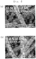
- FIGS. 7 and 8 are views showing pictures of a hybrid magnetic fiber according to Example 1 of the present invention.
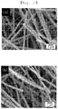
- FIG. 13 is a view showing pictures of a hybrid magnetic fiber according to Example 2 of the present invention.
- an SEM picture was taken of the hybrid magnetic fiber according to above Example 2, which was formed by controlling a molar fraction of the rare-earth element in the source solution to be 12.5 at%, 3.18 at% and 0 at%, and was shown in (a) to (c) of FIG. 13 , respectively.
- the hybrid magnetic fiber is easily formed even if Nd is used as a rare-earth element and Fe is used as a transition-metal element.
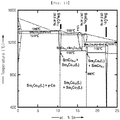
- FIG. 14 is a graph showing an Sm-Co two-ingredient system.
- FIG. 14 a state of a Sm-Co compound according to a molar fraction (at%) of Sm in the Sm-Co compound and temperature (°C) is shown. As can be understood from FIG. 14 , it was confirmed that a hard-magnetic property and a soft-magnetic property coexist if a molar fraction of Sm in the Sm-Co compound is less than 10.6 at%.
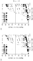
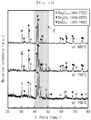
- FIG. 15 is a graph showing an effect of a molar fraction of rare-earth element contained in a source solution on a structure of a hybrid magnetic fiber according to Example 2 of the present invention.
- FIG. 18 is a graph showing properties of a hybrid magnetic fiber according to a comparative example of the present invention, to which a magnetic exchange-coupling effect does not occur.
- magnetization (emu/g) was measured depending on an applied field (kOe) of the hybrid magnetic fiber according to the comparative example of the present invention, in which the Sm 2 Co 17 hard-magnetic material and the fcc-Co soft-magnetic material are simply mixed in a volume ratio of 50 vol%: 50 vol%, so that a hysteresis curve was shown.
- the hybrid magnetic fiber according to above Example 1 in which a volume fraction of the Sm 2 Co 17 magnetic crystal and the fcc-Co magnetic boundary layer was controlled to be 50 vol%: 50 vol%, showed a kink phenomenon, and thus it was confirmed that a magnetic exchange-coupling effect does not occur.
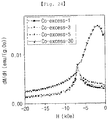
- FIG. 19 is a graph showing an effect of a volume fraction of a magnetic boundary layer on magnetic properties of a hybrid magnetic fiber according to Example 1 of the present invention.
- magnetization (emu/g) was measured depending on an applied field (Oe) of the hybrid magnetic fiber according to above Example 1, in which a volume fraction of the fcc-Co magnetic boundary layer is controlled, so that a hysteresis curve was shown.
- the hybrid magnetic fiber according to Example 1 of the present invention did not show a kink phenomenon in the hysteresis curve unlike the hybrid magnetic fiber according to the comparative example shown in FIG. 18 , so that it was confirmed that a magnetic exchange-coupling effect occurs.
- the hybrid magnetic fiber according to above Example 1 shows the highest maximum magnetic energy product ((BH) max ) value if a volume fraction of the fcc-Co magnetic boundary layer is 1 vol%. Accordingly, it was understood that a magnetic exchange-coupling effect is maximally implemented between Sm 2 Co 17 magnetic crystals and fcc-Co magnetic boundary layer if a volume fraction of the fcc-Co magnetic boundary layer is 1 vol%.
- a size of the soft-magnetic material needs to be smaller than such a value that is twice as much as a domain-wall width of a hard-magnetic material domain boundary.
- a theoretical size of the fcc-Co magnetic boundary layer required to show the magnetic exchange-coupling effect between the Sm 2 Co 17 magnetic crystals and the fcc-Co magnetic boundary layer was about 20.0 nm, which was less than about 5 at% if calculated as a volume fraction. Thus, it can be understood that the size substantially corresponds to experimental data of the present invention.
- FIG. 20 is a graph showing an effect of a volume fraction of magnetic crystals on a remanent magnetization value of a hybrid magnetic fiber according to Example 1 of the present invention.
- FIG. 21 is a graph showing an effect of a volume fraction of magnetic crystals on a maximum magnetic energy product value of a hybrid magnetic fiber according to Example 1 of the present invention.
- the hybrid magnetic fiber according to above Example 1 has a magnetic exchange-coupling effect easily generated between the Sm 2 Co 17 magnetic crystals and the fcc-Co magnetic boundary layer if a volume fraction of the fcc-Co magnetic boundary layer is more than 0 vol% and less than 3 vol%.
- hybrid magnetic fiber with a closed loop shows a magnetic exchange-coupling effect between the Sm 2 Co 17 magnetic crystals and the fcc-Co magnetic crystal layer, but the hybrid magnetic fiber with an opened loop does not show a magnetic exchange-coupling effect between the Sm 2 Co 17 magnetic crystals and the fcc-Co magnetic crystal layer.
- FIG. 24 is a graph showing a recoil susceptibility value of hybrid magnetic fibers according to Example 1 of the present invention, which have different volume fractions of a magnetic crystal layer.
- one peak means that a magnetic exchange-coupling effect appears between the Sm 2 Co 17 magnetic crystals and the fcc-Co magnetic crystal layer, and two peaks mean that a magnetic exchange-coupling effect does not appear between the Sm 2 Co 17 magnetic crystals and the fcc-Co magnetic crystal layer.
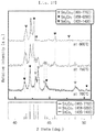
- the rare-earth oxide is not easily reduced if a temperature of heat treatment is 400°C and 500°C in the reducing step, and thus a mixed structure between the Sm 2 Co 17 magnetic crystals and the fcc-Co magnetic crystal layer is not measured.
- a mixed structure between the Sm 2 Co 17 magnetic crystals and the fcc-Co magnetic crystal layer is not measured, if a temperature of heat treatment is 800°C in the reducing step.
- a mixed structure between the Sm 2 Co 17 magnetic crystals and the fcc-Co magnetic crystal layer is easily measured, if a temperature of heat treatment is 600°C, 700°C and 750°C in the reducing step.
- FIGS. 28 is a graph showing a change in properties according to a temperature of heat treatment in a rare-earth oxide.
- an Sm 2 O 3 rare-earth oxide was heat-treated under a hydrogen atmosphere at a heating rate of 10°C/min from 25°C to 1000°C, after which a weight loss (%) of the heat-treated rare-earth oxide was measured and shown. As can be understood from FIG. 28 , it was confirmed that the rare-earth oxide has almost no weight loss even when heat-treated at 1000°C, and thus reduction does not easily occur.
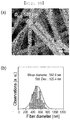
- FIGS. 29 to 31 are pictures and graphs showing a comparison of diameters of hybrid magnetic fibers according to Examples 1 and 3 of the present invention.
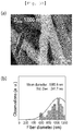
- an SEM picture was taken of the hybrid magnetic fibers according to above Example 1 having a diameter of about 500 nm and a diameter of about 1000 nm and shown in (a) of FIG. 30 and (a) of FIG. 31 , respectively, and a diameter of each hybrid magnetic fiber was measured and shown in (b) of FIG. 30 and (b) of FIG. 31 .
- the hybrid magnetic fibers according to above Example 1 having a diameter of about 500 nm and a diameter of about 1000 nm have a structure of magnetic crystal-magnetic boundary layer.
- a hybrid magnetic fiber may be used in various fields of industry such as permanent magnet, an electric motor, a micro relay, a sensor, etc.
Landscapes
- Engineering & Computer Science (AREA)
- Power Engineering (AREA)
- Chemical & Material Sciences (AREA)
- Textile Engineering (AREA)
- Inorganic Chemistry (AREA)
- Crystallography & Structural Chemistry (AREA)
- Manufacturing & Machinery (AREA)
- Mechanical Engineering (AREA)
- Chemical Kinetics & Catalysis (AREA)
- General Chemical & Material Sciences (AREA)
- Dispersion Chemistry (AREA)
- Powder Metallurgy (AREA)
- Hard Magnetic Materials (AREA)
- Spinning Methods And Devices For Manufacturing Artificial Fibers (AREA)
Applications Claiming Priority (3)
| Application Number | Priority Date | Filing Date | Title |
|---|---|---|---|
| KR20180077099 | 2018-07-03 | ||
| KR1020190011806A KR102125168B1 (ko) | 2018-07-03 | 2019-01-30 | 하이브리드 자성 섬유 및 그 제조방법 |
| PCT/KR2019/001363 WO2020009303A1 (fr) | 2018-07-03 | 2019-01-31 | Fibre magnétique hybride et son procédé de fabrication |
Publications (2)
| Publication Number | Publication Date |
|---|---|
| EP3819924A1 true EP3819924A1 (fr) | 2021-05-12 |
| EP3819924A4 EP3819924A4 (fr) | 2022-04-06 |
Family
ID=69059715
Family Applications (1)
| Application Number | Title | Priority Date | Filing Date |
|---|---|---|---|
| EP19830775.3A Withdrawn EP3819924A4 (fr) | 2018-07-03 | 2019-01-31 | Fibre magnétique hybride et son procédé de fabrication |
Country Status (2)
| Country | Link |
|---|---|
| EP (1) | EP3819924A4 (fr) |
| WO (1) | WO2020009303A1 (fr) |
Family Cites Families (10)
| Publication number | Priority date | Publication date | Assignee | Title |
|---|---|---|---|---|
| WO2009117718A1 (fr) * | 2008-03-20 | 2009-09-24 | Northeastern University | Synthèse chimique directe de matériaux magnétiques en alliage de métal de transition-terre rare |
| KR101483319B1 (ko) * | 2010-10-26 | 2015-01-16 | 한양대학교 에리카산학협력단 | 희토류금속 수소화물 제조 방법 및 이를 사용한 희토류금속-천이금속 합금 분말 제조 방법 |
| JP5708454B2 (ja) * | 2011-11-17 | 2015-04-30 | 日立化成株式会社 | アルコール系溶液および焼結磁石 |
| KR101778164B1 (ko) * | 2012-02-03 | 2017-09-13 | 엘지전자 주식회사 | 코어-쉘 구조를 가지는 경-연자성 혼성 구조의 나노입자, 상기 나노입자를 이용하여 제조한 자석 및 이들의 제조방법 |
| KR101649653B1 (ko) * | 2012-03-30 | 2016-08-19 | 엘지전자 주식회사 | 무전해 또는 전해 증착법을 이용한 나노복합 자석의 제조방법 |
| KR102215818B1 (ko) * | 2013-09-24 | 2021-02-17 | 엘지전자 주식회사 | 비자성 합금을 포함하는 열간가압변형 자석 및 이의 제조방법 |
| KR20160032417A (ko) | 2014-09-16 | 2016-03-24 | 국방과학연구소 | 양팔 매니퓰레이터에 트랙이 결합된 구난 로봇 |
| KR101886558B1 (ko) * | 2016-03-04 | 2018-08-08 | 한양대학교 에리카산학협력단 | 자성 나노 구조체의 제조 방법 |
| KR20170108468A (ko) | 2016-03-17 | 2017-09-27 | 연세대학교 산학협력단 | 보자력이 향상된 비희토류 영구자석 및 이의 제조방법 |
| KR101729687B1 (ko) * | 2016-08-19 | 2017-05-22 | 주식회사 아모라이프사이언스 | 초상자성 나노복합체의 제조방법 및 이를 이용하여 제조된 초상자성 나노복합체 |
-
2019
- 2019-01-31 EP EP19830775.3A patent/EP3819924A4/fr not_active Withdrawn
- 2019-01-31 WO PCT/KR2019/001363 patent/WO2020009303A1/fr not_active Ceased
Also Published As
| Publication number | Publication date |
|---|---|
| WO2020009303A1 (fr) | 2020-01-09 |
| EP3819924A4 (fr) | 2022-04-06 |
Similar Documents
| Publication | Publication Date | Title |
|---|---|---|
| CN101276665B (zh) | 稀土类磁铁及其制造方法 | |
| Deheri et al. | Sol− gel based chemical synthesis of Nd2Fe14B hard magnetic nanoparticles | |
| KR102125168B1 (ko) | 하이브리드 자성 섬유 및 그 제조방법 | |
| US9373432B2 (en) | Alcoholic solution and sintered magnet | |
| US7927501B2 (en) | Rare earth element magnet and method of manufacturing same | |
| US20150187494A1 (en) | Process for preparing rare earth magnets | |
| CN102208235A (zh) | 磁性材料及使用该磁性材料的电动机 | |
| WO1999033597A1 (fr) | POUDRE D'ALLIAGE DE Sm-Fe-N ET PROCEDE DE PRODUCTION | |
| CN103187811A (zh) | 烧结磁铁电动机 | |
| CN101794651A (zh) | 稀土类磁铁 | |
| CN114999756A (zh) | 一种合金粘结剂、复合稀土永磁材料及其制备方法 | |
| KR20190085442A (ko) | 희토류 자석 | |
| KR101837280B1 (ko) | 희토류계 소결 자석의 제조방법 | |
| JP6485066B2 (ja) | 窒化鉄系磁石 | |
| JP6520168B2 (ja) | 窒化鉄系磁性粉末及びそれを用いたボンド磁石 | |
| EP3819924A1 (fr) | Fibre magnétique hybride et son procédé de fabrication | |
| JP7309260B2 (ja) | 焼結磁石の製造方法 | |
| KR102207618B1 (ko) | 철(Fe)을 포함하는 자성 나노 구조체 및 그 제조방법 | |
| EP3996115A1 (fr) | Structure magnétique fibreuse et son procédé de fabrication | |
| JPH1161205A (ja) | 希土類元素・鉄・ボロン系永久磁石合金粉末の製造方法及びその方法で製造される永久磁石合金粉末 | |
| JP6485065B2 (ja) | 窒化鉄系磁性粉末及びそれを用いたボンド磁石 | |
| WO2003088280A1 (fr) | Procede de fabrication de poudre d'alliage d'aimant permanent de fer au neodyme et de bore | |
| KR102045771B1 (ko) | 산화철 자성 분말 및 이의 제조방법 | |
| WO2020137741A1 (fr) | Aimant et procédé de production d'aimant | |
| JP6344129B2 (ja) | 窒化鉄系磁性粉末及びそれを用いた磁石 |
Legal Events
| Date | Code | Title | Description |
|---|---|---|---|
| STAA | Information on the status of an ep patent application or granted ep patent |
Free format text: STATUS: THE INTERNATIONAL PUBLICATION HAS BEEN MADE |
|
| PUAI | Public reference made under article 153(3) epc to a published international application that has entered the european phase |
Free format text: ORIGINAL CODE: 0009012 |
|
| STAA | Information on the status of an ep patent application or granted ep patent |
Free format text: STATUS: REQUEST FOR EXAMINATION WAS MADE |
|
| 17P | Request for examination filed |
Effective date: 20201201 |
|
| AK | Designated contracting states |
Kind code of ref document: A1 Designated state(s): AL AT BE BG CH CY CZ DE DK EE ES FI FR GB GR HR HU IE IS IT LI LT LU LV MC MK MT NL NO PL PT RO RS SE SI SK SM TR |
|
| DAV | Request for validation of the european patent (deleted) | ||
| DAX | Request for extension of the european patent (deleted) | ||
| A4 | Supplementary search report drawn up and despatched |
Effective date: 20220307 |
|
| RIC1 | Information provided on ipc code assigned before grant |
Ipc: H01F 1/055 20060101ALI20220301BHEP Ipc: H01F 41/02 20060101AFI20220301BHEP |
|
| REG | Reference to a national code |
Ref country code: DE Ref legal event code: R079 Free format text: PREVIOUS MAIN CLASS: H01F0041020000 Ipc: H01F0001000000 |
|
| GRAP | Despatch of communication of intention to grant a patent |
Free format text: ORIGINAL CODE: EPIDOSNIGR1 |
|
| STAA | Information on the status of an ep patent application or granted ep patent |
Free format text: STATUS: GRANT OF PATENT IS INTENDED |
|
| RIC1 | Information provided on ipc code assigned before grant |
Ipc: H01F 1/00 20060101AFI20241024BHEP |
|
| INTG | Intention to grant announced |
Effective date: 20241122 |
|
| STAA | Information on the status of an ep patent application or granted ep patent |
Free format text: STATUS: THE APPLICATION IS DEEMED TO BE WITHDRAWN |
|
| 18D | Application deemed to be withdrawn |
Effective date: 20250325 |