EP3820003B1 - Dispositif d'essai de câble - Google Patents
Dispositif d'essai de câble Download PDFInfo
- Publication number
- EP3820003B1 EP3820003B1 EP19207971.3A EP19207971A EP3820003B1 EP 3820003 B1 EP3820003 B1 EP 3820003B1 EP 19207971 A EP19207971 A EP 19207971A EP 3820003 B1 EP3820003 B1 EP 3820003B1
- Authority
- EP
- European Patent Office
- Prior art keywords
- guide
- cable
- support
- handling device
- holder
- Prior art date
- Legal status (The legal status is an assumption and is not a legal conclusion. Google has not performed a legal analysis and makes no representation as to the accuracy of the status listed.)
- Active
Links
Images



Classifications
-
- H—ELECTRICITY
- H01—ELECTRIC ELEMENTS
- H01R—ELECTRICALLY-CONDUCTIVE CONNECTIONS; STRUCTURAL ASSOCIATIONS OF A PLURALITY OF MUTUALLY-INSULATED ELECTRICAL CONNECTING ELEMENTS; COUPLING DEVICES; CURRENT COLLECTORS
- H01R43/00—Apparatus or processes specially adapted for manufacturing, assembling, maintaining, or repairing of line connectors or current collectors or for joining electric conductors
- H01R43/28—Apparatus or processes specially adapted for manufacturing, assembling, maintaining, or repairing of line connectors or current collectors or for joining electric conductors for wire processing before connecting to contact members, not provided for in groups H01R43/02 - H01R43/26
-
- H—ELECTRICITY
- H01—ELECTRIC ELEMENTS
- H01R—ELECTRICALLY-CONDUCTIVE CONNECTIONS; STRUCTURAL ASSOCIATIONS OF A PLURALITY OF MUTUALLY-INSULATED ELECTRICAL CONNECTING ELEMENTS; COUPLING DEVICES; CURRENT COLLECTORS
- H01R43/00—Apparatus or processes specially adapted for manufacturing, assembling, maintaining, or repairing of line connectors or current collectors or for joining electric conductors
- H01R43/04—Apparatus or processes specially adapted for manufacturing, assembling, maintaining, or repairing of line connectors or current collectors or for joining electric conductors for forming connections by deformation, e.g. crimping tool
- H01R43/048—Crimping apparatus or processes
- H01R43/055—Crimping apparatus or processes with contact member feeding mechanism
-
- H—ELECTRICITY
- H01—ELECTRIC ELEMENTS
- H01R—ELECTRICALLY-CONDUCTIVE CONNECTIONS; STRUCTURAL ASSOCIATIONS OF A PLURALITY OF MUTUALLY-INSULATED ELECTRICAL CONNECTING ELEMENTS; COUPLING DEVICES; CURRENT COLLECTORS
- H01R43/00—Apparatus or processes specially adapted for manufacturing, assembling, maintaining, or repairing of line connectors or current collectors or for joining electric conductors
- H01R43/04—Apparatus or processes specially adapted for manufacturing, assembling, maintaining, or repairing of line connectors or current collectors or for joining electric conductors for forming connections by deformation, e.g. crimping tool
- H01R43/048—Crimping apparatus or processes
- H01R43/05—Crimping apparatus or processes with wire-insulation stripping
-
- H—ELECTRICITY
- H01—ELECTRIC ELEMENTS
- H01R—ELECTRICALLY-CONDUCTIVE CONNECTIONS; STRUCTURAL ASSOCIATIONS OF A PLURALITY OF MUTUALLY-INSULATED ELECTRICAL CONNECTING ELEMENTS; COUPLING DEVICES; CURRENT COLLECTORS
- H01R43/00—Apparatus or processes specially adapted for manufacturing, assembling, maintaining, or repairing of line connectors or current collectors or for joining electric conductors
- H01R43/26—Apparatus or processes specially adapted for manufacturing, assembling, maintaining, or repairing of line connectors or current collectors or for joining electric conductors for engaging or disengaging the two parts of a coupling device
Definitions
- the invention relates to a cable handling device for handling a cable, in particular for gripping a cable and/or for feeding a cable to one or more cable processing station(s), according to the preamble of claim 1 and a cable processing device according to the preamble of claim 15.
- the EP1548903B1 discloses a cable processing device with processing stations for assembling a cable, with a feed device with a guide tube feeding the cable to the processing stations.
- the holder also has a spring-loadable pressure piece which presses against the guide tube.
- the aim of the present invention is therefore to overcome the disadvantages resulting from the prior art and to provide a cable handling device in which the fitting with a cable guide or the replacement of the cable guide is carried out manually by the worker in a simple, inexpensive and reliable manner can.
- it should be prevented that Cable guide escapes from the holder during operation.
- the cable handling device should ensure a high degree of accuracy. In preferred embodiments, it should also be possible to reliably avoid erroneous fittings.
- This measure not only ensures precise positioning of the cable guide, but also its reliable attachment.
- the support interacting with the guide ensures, on the one hand, a stable arrangement or accommodation of the cable guide and, on the other hand, a precise positioning with the guide.
- an unintentional or undesired loss of the cable guide from the holder (for example as a result of vibrations, impacts or the mere movement of the holder) is made more difficult or even impossible due to the formation of a guide.
- incorrect assembly is not possible and the handling of the unit formed from the carrier and cable guide, in particular its insertion into the holder, is very easy and can be done with one hand.
- the conversion to the present one is also possible on existing cable processing equipment manual cable handling device according to the invention can be carried out reliably and inexpensively with few components.
- the cable guide is thus introduced into the guide via the insertion point and is pushed along the guide until the cable guide reaches its working position (relative to the holder). In the working position, the cable guide or the opening of the cable guide (through which the cable runs) is aligned with a passage opening for the cable formed in the holder, so that the cable can be passed through the area of the holder.
- the cable routing direction (ie the orientation of the cable routing) is usually essentially horizontal, so that the guiding direction of the guide (the holder) is transverse, preferably perpendicular, to the horizontal.
- a preferred embodiment is characterized in that the guiding direction of the guide is vertical or deviates from the vertical by at most 45°.
- the result is a holder from which the cable guide and carrier cannot be lost simply due to gravity.
- the guide preferably has a barrier in the region of its end—opposite the insertion point—which prevents the carrier from being inserted via this end of the guide and/or acts as a stop to limit the displacement path of the carrier within the guide.
- the barrier can thus define a stop position, which at the same time corresponds to the working position of the cable guide relative to the holder.
- a preferred embodiment is characterized in that the guide of the holder is a linear guide. This measure is characterized by a simple construction and a low displacement resistance.
- the width of the guide is preferably adjustable.
- a preferred embodiment is characterized in that the guide of the holder is formed from two opposite rails, between which the carrier is inserted, with preferably at least one rail being adjustable transversely to the guide direction of the guide and preferably transversely to the cable guide direction.
- the two rails ensure reliable and precisely positioned guidance.
- the guide of the holder and the carrier together can form a device in the manner of a sliding door.
- a preferred embodiment is characterized in that the cable guide is detachably attached to the carrier, preferably by means of at least one screw.
- the carrier is thus an adapter, which acts as a link between the cable guide on the one hand and the guide on the other.
- the use of at least two carriers is effective, of which the first carrier with mounted cable guide is used for cable production on a swiveling unit, while the other carrier is available for conversion with a different cable guide outside of the cable processing station.
- a preferred embodiment is characterized in that the cable guide has an elongate section projecting from the carrier has, wherein preferably a holding section of the cable guide, which preferably has a larger cross section than the protruding elongate section, is arranged in or on the carrier.
- the holding section which may be wider, allows the cable guide to be connected to the carrier.
- the length of the guide is preferably at least twice as great as the maximum extension of the elongate section--protruding from the carrier--in a direction transverse to the cable routing direction.
- the length of the guide counteracts tilting of the carrier in the guide.
- a preferred embodiment is characterized in that the holder has at least one--preferably mechanical or magnetic--safety device, preferably in the form of a locking device, which locks the carrier located in the guide in a position which corresponds to the working position of the cable guide.
- the securing ensures that, in addition to being held by the guide, the working position is secured, i.e. the carrier is fixed in the working position.
- the safety device can, for example, be designed in such a way that it is necessary to overcome a force in order to get into this locked position and/or out of this locked position.
- a spring can be used for this and interact with a securing element or latching element.
- the fuse is preferably arranged in the area below the cable guide and/or asymmetrically in relation to the cable guide. When inserting the carrier from above, it only comes together with the fuse shortly before the working position is reached.
- a preferred embodiment is characterized in that the fuse comprises a securing element which can be moved transversely to the guiding direction of the guide and/or presses onto the carrier or the cable guide transversely to the guiding direction. This can restrict or make it more difficult to move along the guide (out of the working position).
- a preferred embodiment is characterized in that, in the locked state, the securing element protrudes into a recess formed in the carrier, in particular in the form of a depression or a hole or a bore. This further increases the positioning accuracy.
- a preferred embodiment is characterized in that the securing element is acted upon by a spring in the direction of the carrier and/or that the securing element--at least on the side facing the carrier or the cable guide--is of spherical design. This is a particularly elegant and easy-to-use solution.
- a preferred embodiment is characterized in that the holder has at least one releasable lock, preferably in the form of a pawl-spring system, which locks the carrier in the guide, the lock preferably being in the locked state in a direction that is parallel has a component standing in relation to the guiding direction of the guide, acts on the carrier or the cable guide, the locking device preferably being formed in the region of the insertion point.
- the lock can be provided as an alternative or in addition to securing and thus make it more difficult or prevent the undesired removal of the cable guide from the holder.
- a preferred embodiment is characterized in that the carrier is fixed by the mount in a direction parallel to the cable routing direction.
- the carrier inserted into the guide has no degree of freedom in the direction of the cable routing - apart from a possible play.
- a preferred embodiment is characterized in that the carrier extends transversely, preferably perpendicularly, to the cable routing direction.
- a preferred embodiment is characterized in that the carrier is elongate parallel to the guiding direction of the guide.
- a preferred embodiment is characterized in that the carrier is plate-shaped.
- a preferred embodiment is characterized in that the end of the carrier on the insertion side is formed by a rounding. As a result, the insertion of the carrier into the guide of the holder is made much easier and tilting at the beginning of the insertion movement is efficiently prevented.
- a preferred embodiment is characterized in that, in addition to a first section that can be inserted into the guide, the carrier has a second section that has a greater extent in at least one direction transverse to the guiding direction of the guide than the first section, with the second section preferably being extends beyond the bracket and / or wherein preferably the second Section is a handling section for handling the carrier by an operator.
- the second section can be designed in such a way that, when the cable guide is in the working position, it rests against the insertion point of the guide, thereby preventing the carrier from being pushed further into the guide.
- a preferred embodiment is characterized in that the cable handling device has at least one gripper for gripping the cable, with the cable guide preferably extending predominantly in the area in front of the holder and the gripper being arranged in the area behind the holder.
- the gripper grips the cable e.g. during a movement of the holder (e.g. towards a cable processing machine).
- the gripper can be formed, for example, from at least two gripping jaws that can be moved towards one another and thus reach a gripping position.
- a magnetic or electrostatic gripper would also be conceivable.
- a preferred embodiment is characterized in that the holder is arranged on a unit that can be moved linearly and/or pivoted—preferably about a vertical pivot axis—relative to a base—preferably in the horizontal direction. These degrees of freedom are required to feed the cable (e.g. from one cable processing station) to another cable processing station.
- a preferred embodiment is characterized in that readable information, in particular in the form of a code, is arranged, preferably applied or incorporated, in particular engraved, on the carrier and/or on the cable guide, the information preferably being the type and/or size of the cable routing and/or a part designation and/or a size designation.
- a preferred embodiment is characterized in that the cable handling device has at least one sensor device, preferably a camera, for reading out information arranged on the carrier and/or on the cable guide, with the sensor device preferably being connected to a control device of the cable handling device, which control device is connected to it is designed to check the information regarding the cables to be handled, in particular to compare the size of the cables to be handled with the size of the cable guide. If the check shows that the cable routing is unsuitable for the cable to be handled, an error message is displayed, with the processing of the cable being stopped or not started at the cable processing station.
- the sensor device preferably a camera
- a cable processing device with at least one cable processing station and at least one cable handling device according to the invention for feeding a cable to the at least one cable processing station, with the at least one cable processing station preferably having a stripping station (for stripping an (end) section of a cable) and/or or a crimping station (for crimping the cable end) and/or a connector assembly station (for attaching a connector to a cable end).
- a cable processing device with at least one cable processing station and at least one cable handling device according to the invention for feeding a cable to the at least one cable processing station, with the at least one cable processing station preferably having a stripping station (for stripping an (end) section of a cable) and/or or a crimping station (for crimping the cable end) and/or a connector assembly station (for attaching a connector to a cable end).
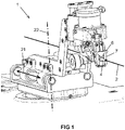
- cable handling device 1 for handling a cable 2, in particular for gripping a cable 2 (see gripper 15 in figure 5 ) and/or for feeding a cable 2 to one or more cable processing station(s) 3 (see 6 ).
- the cable handling device 1 has a cable guide 4 (here in the form of a guide tube) which defines a cable guide direction 5 .
- the cable guide 4 is held by a bracket 7, the cable guide 4 being removable from the bracket 7.
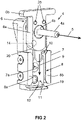
- the cable guide 4 is arranged on a carrier 6 .
- the holder 7 forms a guide 8 whose guide direction 9 is transverse (here perpendicular) to the cable guide direction 5 .
- the carrier 6 is inserted into the guide 8 via an insertion point 10 .
- the carrier 6 is guided by the guide 8 and can be displaced along the guide direction 9 .
- the cable guide 4 or the opening of the cable guide 4 is aligned with a passage opening 7a formed in the holder 7 for the cable 2, so that the cable 2 can be passed through the area of the holder 7.
- the guiding direction 9 of the guide 8 is vertical. A deviation from the vertical of at most 45° would also be preferred.
- the insertion point 10 is formed at the upper end of the guide 8 .
- the guide 8 In the area of its (lower) end - opposite the insertion point 10 - the guide 8 has a barrier 19 which prevents the carrier 6 from being inserted via this (lower) end of the guide 8 and/or prevents the carrier 6 from being displaced within the guide 8 limited.
- the guide 8 of the holder 7 is a linear guide.
- (circular) arc-shaped guides would also be conceivable.
- the width of the guide 8 can be adjustable. In the Figures 2-3 two adjusting screws are provided for this purpose in the lateral area of the holder 7 .
- the guide 8 can be formed from two opposing rails 8a, 8b, between which the carrier 6 is inserted.
- the guide 8 of the holder 7 and the carrier 6 form a device in the form of a sliding door (here: closable from above).
- at least one rail 8a, 8b can be adjusted transversely to the guide direction 9 of the guide 8 and preferably transversely to the cable guide direction 5 (by means of the adjusting screws shown).
- the cable guide 4 can be detachably--and thus interchangeably--attached to the carrier 6, preferably by means of at least one screw 25 (see FIG 2 ).
- the cable guide 4 can have an elongate section 4a projecting from the carrier 6.
- a holding section 4b of the cable guide 4 is arranged in or on the carrier 6 .
- the holding section has a larger cross section than the protruding elongate section 4a.
- the length of the guide 8 is preferably at least twice as great as the maximum extent of the elongated section 4a - protruding from the carrier 6 - in a direction transverse to the cable guide direction 5 or in a direction parallel to the guide direction 9 of the guide 8.
- the bracket 7 - in the Figures 1-4 - Has at least one - here mechanical or alternatively magnetic - fuse 11, preferably in the form of a locking device on.
- the fuse 11 locks the carrier 6 located in the guide 8 in a position which corresponds to the working position of the cable guide 4 (relative to the holder 7).
- the fuse 11 in Can be arranged in relation to the cable guide 4 area below the cable guide 4 and / or asymmetrically.
- the fuse 11 comprises a securing element 12 which can be moved transversely to the guide direction 9 of the guide 8 or—in the secured or locked state—presses transversely to the guide direction 9 onto the carrier 6 or the cable guide 4 .
- the carrier 6 is fixed by the holder 7 in a direction parallel to the cable routing direction 5, so that locking is effected by the securing element 12 pressing transversely to the routing direction 9.
- the securing element 12 can protrude into a recess 14 formed in the carrier 6, in particular in the form of a depression or a hole or a bore.
- the securing element 12 is acted upon by a spring 13 in the direction of the carrier 6 .
- the securing element 12 can be spherical or—preferably conical—converging, at least on the side facing the carrier 6 or the cable guide 4 .
- the holder 7 can have at least one releasable locking device 24, preferably in the form of a latch-spring system, which locks the carrier 6 in the guide 8.
- a lock 24 is shown purely schematically. In the locked state, the lock 24 can act on the carrier 6 or the cable guide 4 in a direction which has a component which is parallel to the guide direction 9 of the guide 8 .
- the lock 24 is preferably formed in the area of the insertion point 10 .
- the carrier 6 shown in the figures extends transversely (perpendicular here) to the cable routing direction 5 and is parallel to the Guide direction 9 of the guide 8 elongated. As the figures show, the carrier 6 can be plate-shaped.
- the end of the carrier 6 on the insertion side can be formed by a rounding 20 to facilitate the insertion movement.
- the carrier 6 can have a second section 6b, which has a greater extent in at least one direction transverse to the guide direction 9 of the guide 8 than the first section 6a.
- the second section 6b can extend (laterally) beyond the holder and thus form, for example, a handling section for handling the carrier 6 by an operator.
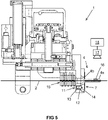
- the cable handling device 1 preferably has - as in figure 5 to see - at least one gripper 15 for gripping the cable 2 on.
- the cable guide 4 can be predominantly in the area in front of (in figure 5 right) of the holder 7 and the gripper 15 in the area behind (in figure 5 left) of the holder 7 can be arranged.
- figure 5 also shows that the holder 7 can be arranged on a unit 23, which can be linearly moved and/or pivoted, preferably about a vertical pivot axis 22, relative to a base—preferably in the horizontal direction 21.
- FIG 5 shows another preferred aspect of the invention.
- Readable information 16 in particular in the form of a code, is arranged on the carrier 6 and/or on the cable guide 4, preferably applied or incorporated, in particular engraved.
- the information contains the type and/or size of the cable guide 4 and/or a part designation and/or a size designation.
- the cable handling device 1 can further at least one sensor device 17, such as a camera, for Reading the information 16 have.
- the sensor device 17 is connected to a control device 18 of the cable handling device 1 .
- the control device 18 is designed to check the information 16 with regard to the cables 2 to be handled, in particular to compare the size of the cables 2 to be handled with the size of the cable guide 4 .
- the cable processing stations 3 can include, for example, a stripping station and/or a crimping station and/or a connector assembly station.
- the cable processing stations 3 are arranged on a circular arc of approximately 90 degrees.
- the stripping station as one of the cable processing stations 3 is located exactly at 0 degrees (ie on the conveying axis of the conveying direction).
- the cable processing stations 3 are located next to each other in a circular arc area of about 45 degrees, so that they can be approached by the cable handling device side 1.
- the invention is not limited to the embodiments described and the aspects highlighted therein.
Landscapes
- Engineering & Computer Science (AREA)
- Manufacturing & Machinery (AREA)
- Installation Of Indoor Wiring (AREA)
Claims (15)
- Dispositif de manipulation de câble (1) pour la manipulation d'un câble (2), en particulier pour la saisie d'un câble (2) et/ou pour l'acheminement d'un câble (2) vers une ou plusieurs stations d'usinage de câble(3), comprenant- un guide-câble (4), de préférence sous la forme d'un tuyau de guidage à travers lequel un sens de guidage de câble (5) est défini, et- une fixation (7) pour retenir le guide-câble (4),caractérisé en ce que
le guide-câble (4) pouvant être enlevé du support (7),- le guide-câble (4) est disposé au niveau d'un support (6),- la fixation (7) constitue un guide (8) dont le sens de guidage (9) est transversal, de préférence perpendiculaire, au sens de guidage du câble (5) et qui présente un point d'introduction (10) pour introduire le support (6) dans le guide (8), et que- le support (6) est guidé par le guide (8) et est déplaçable le long du sens de guidage (9) . - Dispositif de manipulation de câble selon la revendication 1, caractérisé en ce que le sens de guidage (9) du guide (8) est vertical ou diverge au plus de 45° de la verticale,et/ou que le point d'introduction (10) est réalisé à l'extrémité supérieure du guide (8),et/ou que le guide (8) présente, au niveau de son extrémité - opposée au point d'introduction (10) - une barrière (19) qui empêche une introduction du support (6) par cette extrémité du guide (8) et/ou limite en tant que butée la course de déplacement du support (6) à l'intérieur du guide (8).
- Dispositif de manipulation de câble selon la revendication 1 ou 2, caractérisé en ce que le guide (8) de la fixation (7) est un guide linéaire,et/ou que la largeur du guide (8) est réglable,et/ou que le guide (8) de la fixation (7) est constitué de deux rails opposés (8a, 8b) entre lesquels le support (6) est inséré, au moins un rail (8a, 8b) étant de préférence réglable transversalement au sens de guidage (9) du guide (8) et de préférence transversalement au sens de guidage du câble (5),et/ou que le guide (8) de la fixation (7) et le support (6) constituent un système de type porte coulissante.
- Dispositif de manipulation de câble selon une des revendications précédentes, caractérisé en ce que le guide-câble (4) est fixé de manière dissociable au support (6), de préférence au moyen d'au moins une vis,
et/ou que le guide-câble (4) présente une section allongée (4a) dépassant du support (6), une section de retenue (4b) du guide-câble (4), qui présente de préférence une section transversale supérieure à celle de la section allongée proéminente (4a), étant de préférence disposée dans ou sur le support (6), et/ou la longueur du guide (8) représentant de préférence au moins le double de l'extension maximale de la section allongée (4a) - dépassant du support (6) - dans un sens transversal au sens de guidage du câble (5). - Dispositif de manipulation de câble selon une des revendications précédentes, caractérisé en ce que la fixation (7) présente au moins une sécurité (11) - de préférence mécanique ou magnétique -, de préférence sous forme d'un dispositif d'enclenchement qui bloque le support (6) se trouvant dans le guide (8) dans une position qui correspond à la position de travail du guide-câble (4), la sécurité (11) étant de préférence disposée dans la zone située en dessous du guide-câble (4) et/ou symétriquement par rapport au guide-câble (4) .
- Dispositif de manipulation de câble selon la revendication 5, caractérisé en ce que la sécurité (11) comprend un élément de blocage (12) qui est mobile transversalement au sens de guidage (9) du guide (8) et/ou appuie sur le support (6) ou le guide-câble (4) transversalement au sens de guidage (9).
- Dispositif de manipulation de câble selon la revendication 6, caractérisé en ce que, en position arrêtée, l'élément de blocage (12) dépasse dans un évidement (14) pratiqué dans le support (6), en particulier sous forme d'un creux ou d'un trou ou d'un alésage.
- Dispositif de manipulation de câble selon la revendication 6 ou 7, caractérisé en ce que l'élément de blocage (12) est sollicité par un ressort (13) en direction du support (6) et/ou que l'élément de blocage (12) est réalisé de manière à converger, de préférence suivant une forme sphérique ou de préférence conique, au moins sur le côté tourné vers le support (6) ou le guide-câble (4).
- Dispositif de manipulation de câble selon une des revendications précédentes, caractérisé en ce que la fixation (7) présente au moins un verrouillage déblocable (24), de préférence sous la forme d'un système à cliquet et ressort, qui verrouille le support (6) dans le guide (8), sachant que le verrouillage (24), en position verrouillée, agit de préférence sur le support (6) ou le guide-câble (4) dans un sens qui présente une composante parallèle au sens de guidage (9) du guide (8), le verrouillage (24) étant établi au niveau du point d'introduction (10).
- Dispositif de manipulation de câble selon une des revendications précédentes, caractérisé en ce que le support (6) est bloqué par la fixation (7) dans un sens parallèle au sens de guidage du câble (5),et/ou que le support (6) s'étend transversalement, de préférence perpendiculairement, au sens de guidage de câble (5),et/ou que le support (6) a une conformation allongée parallèlement au sens de guidage (8) du guide (8),et/ou que le support (6) est réalisé en forme de plaque,et/ou que l'extrémité située du côté introduction du support (6) est constituée par un arrondi (20),et/ou que le support (6), outre une première section (6a) pouvant être introduite dans le guide (8), présente une seconde section (6b) qui, du moins dans un sens transversal au sens de guidage (9) du guide (8), a une extension supérieure à celle de la première section (6a), la seconde section (6b) s'étendant au-delà de la fixation et/ou la seconde section (6b) étant de préférence une section de manipulation pour la manipulation du support (6) par un opérateur.
- Dispositif de manipulation de câble selon une des revendications précédentes, caractérisé en ce que le dispositif de manipulation de câble (1) présente au moins un préhenseur (15) pour saisir le câble (2), le guide-câble (4) s'étendant de préférence majoritairement en amont de la fixation (7) et le préhenseur (15) étant disposé dans la zone située derrière la fixation (7).
- Dispositif de manipulation de câble selon une des revendications précédentes, caractérisé en ce que la fixation (7) est disposée au niveau d'une unité (23) qui est mobile linéairement par rapport à une base - de préférence dans le sens horizontal (21)- et/ou de préférence de manière à pouvoir pivoter autour d'un axe de pivotement vertical (22).
- Dispositif de manipulation de câble selon une des revendications précédentes, caractérisé en ce que, au niveau du support (6) et/ou du guide-câble (4), une information lisible (16), en particulier sous forme d'un code, est disposée, de préférence appliquée ou inscrite, en particulier gravée, cette information contenant le type et/ou la taille du guide-câble (4) et/ou une désignation de pièce et/ou une désignation de taille.
- Dispositif de manipulation de câble selon une des revendications précédentes, caractérisé en ce que le dispositif de manipulation de câble (1) présente au moins un dispositif de détection (17), de préférence une caméra, pour lire une information (16) disposée au niveau du support (6) et/ou du guide-câble (4), le dispositif de détection (17) étant connecté à une unité de commande (18) du dispositif de manipulation de câble (1), laquelle unité de commande (18) est conçue pour contrôler l'information (16) concernant les câbles à manipuler (2), en particulier pour comparer la taille des câbles à manipuler (2) à la taille du guide-câble (4).
- Dispositif de manipulation de câble comportant au moins une station d'usinage de câble (3) et au moins un dispositif de manipulation de câble (1) pour acheminer un câble (2) vers l'au moins une station d'usinage de câble (3), l'au moins une station d'usinage de câble (3) comprenant de préférence une station d'isolation et/ou une station de sertissage et/ou une station de pose de prise, caractérisé en ce que le dispositif de manipulation de câble (1) est réalisé selon une des revendications précédentes.
Priority Applications (2)
| Application Number | Priority Date | Filing Date | Title |
|---|---|---|---|
| EP19207971.3A EP3820003B1 (fr) | 2019-11-08 | 2019-11-08 | Dispositif d'essai de câble |
| CN202011217693.1A CN112864760B (zh) | 2019-11-08 | 2020-11-04 | 线缆操纵设备和线缆加工设备 |
Applications Claiming Priority (1)
| Application Number | Priority Date | Filing Date | Title |
|---|---|---|---|
| EP19207971.3A EP3820003B1 (fr) | 2019-11-08 | 2019-11-08 | Dispositif d'essai de câble |
Publications (2)
| Publication Number | Publication Date |
|---|---|
| EP3820003A1 EP3820003A1 (fr) | 2021-05-12 |
| EP3820003B1 true EP3820003B1 (fr) | 2022-07-20 |
Family
ID=68501414
Family Applications (1)
| Application Number | Title | Priority Date | Filing Date |
|---|---|---|---|
| EP19207971.3A Active EP3820003B1 (fr) | 2019-11-08 | 2019-11-08 | Dispositif d'essai de câble |
Country Status (2)
| Country | Link |
|---|---|
| EP (1) | EP3820003B1 (fr) |
| CN (1) | CN112864760B (fr) |
Family Cites Families (7)
| Publication number | Priority date | Publication date | Assignee | Title |
|---|---|---|---|---|
| EP1548903B1 (fr) | 2003-12-22 | 2007-09-19 | komax Holding AG | Dispositif pour le traitement de câbles |
| WO2016088088A1 (fr) * | 2014-12-04 | 2016-06-09 | Schleuniger Holding Ag | Procédé de montage d'un composant à l'extrémité d'un câble dénudé |
| JP6926119B2 (ja) * | 2016-01-26 | 2021-08-25 | コマツクス・ホールデイング・アー・ゲー | ケーブル処理装置 |
| DE102017107136A1 (de) * | 2016-04-04 | 2017-10-05 | Knorr-Bremse Systeme für Nutzfahrzeuge GmbH | Befestigungsvorrichtung zur Befestigung eines Signalkabels |
| EP3376606B1 (fr) * | 2017-03-17 | 2021-05-05 | Aptiv Technologies Limited | Connecteur de faisceau de câble |
| DE102018107839A1 (de) * | 2018-04-03 | 2019-10-10 | Phoenix Contact Gmbh & Co. Kg | Anschlussvorrichtung zum Anschließen eines Leiters eines Kabels an eine Tragschiene zu deren elektrischen Verbindung miteinander |
| CN110021868B (zh) * | 2019-04-26 | 2024-06-11 | 广东银钢智能科技有限公司 | 线缆切剥扭线装置 |
-
2019
- 2019-11-08 EP EP19207971.3A patent/EP3820003B1/fr active Active
-
2020
- 2020-11-04 CN CN202011217693.1A patent/CN112864760B/zh active Active
Also Published As
| Publication number | Publication date |
|---|---|
| CN112864760A (zh) | 2021-05-28 |
| EP3820003A1 (fr) | 2021-05-12 |
| CN112864760B (zh) | 2025-04-25 |
Similar Documents
| Publication | Publication Date | Title |
|---|---|---|
| EP3209891B1 (fr) | Cheville à bascule et son procédé de montage | |
| EP3472403B1 (fr) | Dispositif servant à fixer un élément en forme de plaque dans une rainure de réception d'un rail de support | |
| DE102009022796B4 (de) | Vorrichtung zum Verlegen eines in einem Flugzeug installierten Kabelstrangs | |
| DE19534386A1 (de) | Werkzeugaufhängung zur Befestigung von Werkzeugen an einem Trägerelement | |
| EP0290989A2 (fr) | Prise de courant montée flottante sur une plaque de montage | |
| EP1809441B1 (fr) | Dispositif de serrage et de prehension, en particulier pince lineaire ou centrale | |
| EP2902582A1 (fr) | Système de mât et procédé de fixation d'un outil de travail au rail de coulissage du mât | |
| DE202014011041U1 (de) | Werkzeughalteranordnung für eine Lochrasterplatte | |
| EP0335081A1 (fr) | Dispositif pour le guidage de produit laminé entre les cylindres d'une cage de laminoir | |
| EP3778059A1 (fr) | Dispositif de réception d'outil, machine de travail pourvue de dispositif de réception d'outil ainsi que procédé de positionnement d'un outil sur un dispositif de réception d'outil | |
| DE102011085793A1 (de) | Halterungsvorrichtung zum Haltern eines Kabels oder einer Leitung an einer Strukturkomponente eines Luft- oder Raumfahrzeugs sowie Luft- oder Raumfahrzeug | |
| DE19940813A1 (de) | Längseinstellvorrichtung für einen Fahrzeugsitz | |
| DE102020106097B3 (de) | Kabelführungs- und Verlege-Hilfsvorrichtung | |
| EP3820003A1 (fr) | Dispositif d'essai de câble | |
| AT518987B1 (de) | Adapter für Rohrklemme | |
| EP0724104A1 (fr) | Elément d'atténuation de contraintes et de fixation | |
| AT523046B1 (de) | Vorrichtung zum Verbinden von Rohren | |
| DE102022129084A1 (de) | Elektrische Bearbeitungsmaschine | |
| DE102018131555B4 (de) | Gurtschloss für ein Sicherheitsgurtsystem eines Kraftwagens | |
| DE202021102997U1 (de) | Baugruppe für ein Crimpwerkzeug und Crimpwerkzeug | |
| EP3741522A1 (fr) | Système de rétraction pour conduites | |
| EP3471982B1 (fr) | Montage en trois points d'une porte coulissante | |
| DE19751502A1 (de) | Greif- und Transporthandhabe sowie Verfahren zum Aufbau und Justieren derselben | |
| DE102020118273A1 (de) | Befestigungssystem zum Befestigen einer optoelektronischen Messvorrichtung, insbesondere eines Lichtgitters, in einer Betriebsposition | |
| DE102024109833B3 (de) | Selbstausrichtende Bohrlehre |
Legal Events
| Date | Code | Title | Description |
|---|---|---|---|
| PUAI | Public reference made under article 153(3) epc to a published international application that has entered the european phase |
Free format text: ORIGINAL CODE: 0009012 |
|
| STAA | Information on the status of an ep patent application or granted ep patent |
Free format text: STATUS: THE APPLICATION HAS BEEN PUBLISHED |
|
| AK | Designated contracting states |
Kind code of ref document: A1 Designated state(s): AL AT BE BG CH CY CZ DE DK EE ES FI FR GB GR HR HU IE IS IT LI LT LU LV MC MK MT NL NO PL PT RO RS SE SI SK SM TR |
|
| STAA | Information on the status of an ep patent application or granted ep patent |
Free format text: STATUS: REQUEST FOR EXAMINATION WAS MADE |
|
| 17P | Request for examination filed |
Effective date: 20211112 |
|
| RBV | Designated contracting states (corrected) |
Designated state(s): AL AT BE BG CH CY CZ DE DK EE ES FI FR GB GR HR HU IE IS IT LI LT LU LV MC MK MT NL NO PL PT RO RS SE SI SK SM TR |
|
| GRAP | Despatch of communication of intention to grant a patent |
Free format text: ORIGINAL CODE: EPIDOSNIGR1 |
|
| STAA | Information on the status of an ep patent application or granted ep patent |
Free format text: STATUS: GRANT OF PATENT IS INTENDED |
|
| INTG | Intention to grant announced |
Effective date: 20220407 |
|
| GRAS | Grant fee paid |
Free format text: ORIGINAL CODE: EPIDOSNIGR3 |
|
| GRAA | (expected) grant |
Free format text: ORIGINAL CODE: 0009210 |
|
| STAA | Information on the status of an ep patent application or granted ep patent |
Free format text: STATUS: THE PATENT HAS BEEN GRANTED |
|
| AK | Designated contracting states |
Kind code of ref document: B1 Designated state(s): AL AT BE BG CH CY CZ DE DK EE ES FI FR GB GR HR HU IE IS IT LI LT LU LV MC MK MT NL NO PL PT RO RS SE SI SK SM TR |
|
| REG | Reference to a national code |
Ref country code: CH Ref legal event code: EP |
|
| REG | Reference to a national code |
Ref country code: DE Ref legal event code: R096 Ref document number: 502019005007 Country of ref document: DE |
|
| REG | Reference to a national code |
Ref country code: AT Ref legal event code: REF Ref document number: 1506159 Country of ref document: AT Kind code of ref document: T Effective date: 20220815 |
|
| REG | Reference to a national code |
Ref country code: IE Ref legal event code: FG4D Free format text: LANGUAGE OF EP DOCUMENT: GERMAN |
|
| REG | Reference to a national code |
Ref country code: LT Ref legal event code: MG9D |
|
| REG | Reference to a national code |
Ref country code: NL Ref legal event code: MP Effective date: 20220720 |
|
| PG25 | Lapsed in a contracting state [announced via postgrant information from national office to epo] |
Ref country code: SE Free format text: LAPSE BECAUSE OF FAILURE TO SUBMIT A TRANSLATION OF THE DESCRIPTION OR TO PAY THE FEE WITHIN THE PRESCRIBED TIME-LIMIT Effective date: 20220720 Ref country code: RS Free format text: LAPSE BECAUSE OF FAILURE TO SUBMIT A TRANSLATION OF THE DESCRIPTION OR TO PAY THE FEE WITHIN THE PRESCRIBED TIME-LIMIT Effective date: 20220720 Ref country code: PT Free format text: LAPSE BECAUSE OF FAILURE TO SUBMIT A TRANSLATION OF THE DESCRIPTION OR TO PAY THE FEE WITHIN THE PRESCRIBED TIME-LIMIT Effective date: 20221121 Ref country code: NO Free format text: LAPSE BECAUSE OF FAILURE TO SUBMIT A TRANSLATION OF THE DESCRIPTION OR TO PAY THE FEE WITHIN THE PRESCRIBED TIME-LIMIT Effective date: 20221020 Ref country code: NL Free format text: LAPSE BECAUSE OF FAILURE TO SUBMIT A TRANSLATION OF THE DESCRIPTION OR TO PAY THE FEE WITHIN THE PRESCRIBED TIME-LIMIT Effective date: 20220720 Ref country code: LV Free format text: LAPSE BECAUSE OF FAILURE TO SUBMIT A TRANSLATION OF THE DESCRIPTION OR TO PAY THE FEE WITHIN THE PRESCRIBED TIME-LIMIT Effective date: 20220720 Ref country code: LT Free format text: LAPSE BECAUSE OF FAILURE TO SUBMIT A TRANSLATION OF THE DESCRIPTION OR TO PAY THE FEE WITHIN THE PRESCRIBED TIME-LIMIT Effective date: 20220720 Ref country code: FI Free format text: LAPSE BECAUSE OF FAILURE TO SUBMIT A TRANSLATION OF THE DESCRIPTION OR TO PAY THE FEE WITHIN THE PRESCRIBED TIME-LIMIT Effective date: 20220720 Ref country code: ES Free format text: LAPSE BECAUSE OF FAILURE TO SUBMIT A TRANSLATION OF THE DESCRIPTION OR TO PAY THE FEE WITHIN THE PRESCRIBED TIME-LIMIT Effective date: 20220720 |
|
| PG25 | Lapsed in a contracting state [announced via postgrant information from national office to epo] |
Ref country code: PL Free format text: LAPSE BECAUSE OF FAILURE TO SUBMIT A TRANSLATION OF THE DESCRIPTION OR TO PAY THE FEE WITHIN THE PRESCRIBED TIME-LIMIT Effective date: 20220720 Ref country code: IS Free format text: LAPSE BECAUSE OF FAILURE TO SUBMIT A TRANSLATION OF THE DESCRIPTION OR TO PAY THE FEE WITHIN THE PRESCRIBED TIME-LIMIT Effective date: 20221120 Ref country code: HR Free format text: LAPSE BECAUSE OF FAILURE TO SUBMIT A TRANSLATION OF THE DESCRIPTION OR TO PAY THE FEE WITHIN THE PRESCRIBED TIME-LIMIT Effective date: 20220720 Ref country code: GR Free format text: LAPSE BECAUSE OF FAILURE TO SUBMIT A TRANSLATION OF THE DESCRIPTION OR TO PAY THE FEE WITHIN THE PRESCRIBED TIME-LIMIT Effective date: 20221021 |
|
| REG | Reference to a national code |
Ref country code: DE Ref legal event code: R097 Ref document number: 502019005007 Country of ref document: DE |
|
| PG25 | Lapsed in a contracting state [announced via postgrant information from national office to epo] |
Ref country code: SM Free format text: LAPSE BECAUSE OF FAILURE TO SUBMIT A TRANSLATION OF THE DESCRIPTION OR TO PAY THE FEE WITHIN THE PRESCRIBED TIME-LIMIT Effective date: 20220720 Ref country code: RO Free format text: LAPSE BECAUSE OF FAILURE TO SUBMIT A TRANSLATION OF THE DESCRIPTION OR TO PAY THE FEE WITHIN THE PRESCRIBED TIME-LIMIT Effective date: 20220720 Ref country code: DK Free format text: LAPSE BECAUSE OF FAILURE TO SUBMIT A TRANSLATION OF THE DESCRIPTION OR TO PAY THE FEE WITHIN THE PRESCRIBED TIME-LIMIT Effective date: 20220720 Ref country code: CZ Free format text: LAPSE BECAUSE OF FAILURE TO SUBMIT A TRANSLATION OF THE DESCRIPTION OR TO PAY THE FEE WITHIN THE PRESCRIBED TIME-LIMIT Effective date: 20220720 |
|
| PLBE | No opposition filed within time limit |
Free format text: ORIGINAL CODE: 0009261 |
|
| STAA | Information on the status of an ep patent application or granted ep patent |
Free format text: STATUS: NO OPPOSITION FILED WITHIN TIME LIMIT |
|
| PG25 | Lapsed in a contracting state [announced via postgrant information from national office to epo] |
Ref country code: SK Free format text: LAPSE BECAUSE OF FAILURE TO SUBMIT A TRANSLATION OF THE DESCRIPTION OR TO PAY THE FEE WITHIN THE PRESCRIBED TIME-LIMIT Effective date: 20220720 Ref country code: EE Free format text: LAPSE BECAUSE OF FAILURE TO SUBMIT A TRANSLATION OF THE DESCRIPTION OR TO PAY THE FEE WITHIN THE PRESCRIBED TIME-LIMIT Effective date: 20220720 |
|
| 26N | No opposition filed |
Effective date: 20230421 |
|
| PG25 | Lapsed in a contracting state [announced via postgrant information from national office to epo] |
Ref country code: MC Free format text: LAPSE BECAUSE OF FAILURE TO SUBMIT A TRANSLATION OF THE DESCRIPTION OR TO PAY THE FEE WITHIN THE PRESCRIBED TIME-LIMIT Effective date: 20220720 Ref country code: AL Free format text: LAPSE BECAUSE OF FAILURE TO SUBMIT A TRANSLATION OF THE DESCRIPTION OR TO PAY THE FEE WITHIN THE PRESCRIBED TIME-LIMIT Effective date: 20220720 |
|
| P01 | Opt-out of the competence of the unified patent court (upc) registered |
Effective date: 20230606 |
|
| REG | Reference to a national code |
Ref country code: BE Ref legal event code: MM Effective date: 20221130 |
|
| PG25 | Lapsed in a contracting state [announced via postgrant information from national office to epo] |
Ref country code: SI Free format text: LAPSE BECAUSE OF FAILURE TO SUBMIT A TRANSLATION OF THE DESCRIPTION OR TO PAY THE FEE WITHIN THE PRESCRIBED TIME-LIMIT Effective date: 20220720 Ref country code: LU Free format text: LAPSE BECAUSE OF NON-PAYMENT OF DUE FEES Effective date: 20221108 |
|
| PG25 | Lapsed in a contracting state [announced via postgrant information from national office to epo] |
Ref country code: IE Free format text: LAPSE BECAUSE OF NON-PAYMENT OF DUE FEES Effective date: 20221108 |
|
| PG25 | Lapsed in a contracting state [announced via postgrant information from national office to epo] |
Ref country code: FR Free format text: LAPSE BECAUSE OF NON-PAYMENT OF DUE FEES Effective date: 20221130 Ref country code: BE Free format text: LAPSE BECAUSE OF NON-PAYMENT OF DUE FEES Effective date: 20221130 |
|
| REG | Reference to a national code |
Ref country code: DE Ref legal event code: R082 Ref document number: 502019005007 Country of ref document: DE Representative=s name: ROSENICH, PAUL, DIPL.-HTL-ING., LI Ref country code: DE Ref legal event code: R082 Ref document number: 502019005007 Country of ref document: DE Representative=s name: ZIMMERMANN & PARTNER PATENTANWAELTE MBB, DE |
|
| PG25 | Lapsed in a contracting state [announced via postgrant information from national office to epo] |
Ref country code: CY Free format text: LAPSE BECAUSE OF FAILURE TO SUBMIT A TRANSLATION OF THE DESCRIPTION OR TO PAY THE FEE WITHIN THE PRESCRIBED TIME-LIMIT Effective date: 20220720 |
|
| PG25 | Lapsed in a contracting state [announced via postgrant information from national office to epo] |
Ref country code: MK Free format text: LAPSE BECAUSE OF FAILURE TO SUBMIT A TRANSLATION OF THE DESCRIPTION OR TO PAY THE FEE WITHIN THE PRESCRIBED TIME-LIMIT Effective date: 20220720 Ref country code: HU Free format text: LAPSE BECAUSE OF FAILURE TO SUBMIT A TRANSLATION OF THE DESCRIPTION OR TO PAY THE FEE WITHIN THE PRESCRIBED TIME-LIMIT; INVALID AB INITIO Effective date: 20191108 |
|
| PG25 | Lapsed in a contracting state [announced via postgrant information from national office to epo] |
Ref country code: TR Free format text: LAPSE BECAUSE OF FAILURE TO SUBMIT A TRANSLATION OF THE DESCRIPTION OR TO PAY THE FEE WITHIN THE PRESCRIBED TIME-LIMIT Effective date: 20220720 |
|
| GBPC | Gb: european patent ceased through non-payment of renewal fee |
Effective date: 20231108 |
|
| PG25 | Lapsed in a contracting state [announced via postgrant information from national office to epo] |
Ref country code: BG Free format text: LAPSE BECAUSE OF FAILURE TO SUBMIT A TRANSLATION OF THE DESCRIPTION OR TO PAY THE FEE WITHIN THE PRESCRIBED TIME-LIMIT Effective date: 20220720 |
|
| PG25 | Lapsed in a contracting state [announced via postgrant information from national office to epo] |
Ref country code: MT Free format text: LAPSE BECAUSE OF FAILURE TO SUBMIT A TRANSLATION OF THE DESCRIPTION OR TO PAY THE FEE WITHIN THE PRESCRIBED TIME-LIMIT Effective date: 20220720 |
|
| PG25 | Lapsed in a contracting state [announced via postgrant information from national office to epo] |
Ref country code: GB Free format text: LAPSE BECAUSE OF NON-PAYMENT OF DUE FEES Effective date: 20231108 |
|
| PG25 | Lapsed in a contracting state [announced via postgrant information from national office to epo] |
Ref country code: GB Free format text: LAPSE BECAUSE OF NON-PAYMENT OF DUE FEES Effective date: 20231108 |
|
| REG | Reference to a national code |
Ref country code: CH Ref legal event code: U11 Free format text: ST27 STATUS EVENT CODE: U-0-0-U10-U11 (AS PROVIDED BY THE NATIONAL OFFICE) Effective date: 20251201 |
|
| PGFP | Annual fee paid to national office [announced via postgrant information from national office to epo] |
Ref country code: DE Payment date: 20251119 Year of fee payment: 7 |
|
| PG25 | Lapsed in a contracting state [announced via postgrant information from national office to epo] |
Ref country code: AT Free format text: LAPSE BECAUSE OF NON-PAYMENT OF DUE FEES Effective date: 20241108 |
|
| PGFP | Annual fee paid to national office [announced via postgrant information from national office to epo] |
Ref country code: IT Payment date: 20251125 Year of fee payment: 7 |
|
| REG | Reference to a national code |
Ref country code: AT Ref legal event code: MM01 Ref document number: 1506159 Country of ref document: AT Kind code of ref document: T Effective date: 20241108 |
|
| PGFP | Annual fee paid to national office [announced via postgrant information from national office to epo] |
Ref country code: CH Payment date: 20251201 Year of fee payment: 7 |
|
| PGFP | Annual fee paid to national office [announced via postgrant information from national office to epo] |
Ref country code: AT Payment date: 20260410 Year of fee payment: 5 |
|
| REG | Reference to a national code |
Ref country code: CH Ref legal event code: R17 Free format text: ST27 STATUS EVENT CODE: U-0-0-R10-R17 (AS PROVIDED BY THE NATIONAL OFFICE) Effective date: 20260417 |
|
| REG | Reference to a national code |
Ref country code: DE Ref legal event code: R082 Ref document number: 502019005007 Country of ref document: DE Representative=s name: ZIMMERMANN & PARTNER PATENTANWAELTE MBB, DE |