EP3820120A2 - Dispositif de traitement des informations, système de traitement des informations et procédé de traitement des informations - Google Patents
Dispositif de traitement des informations, système de traitement des informations et procédé de traitement des informations Download PDFInfo
- Publication number
- EP3820120A2 EP3820120A2 EP20196370.9A EP20196370A EP3820120A2 EP 3820120 A2 EP3820120 A2 EP 3820120A2 EP 20196370 A EP20196370 A EP 20196370A EP 3820120 A2 EP3820120 A2 EP 3820120A2
- Authority
- EP
- European Patent Office
- Prior art keywords
- application
- appliance
- information
- setting
- information processing
- Prior art date
- Legal status (The legal status is an assumption and is not a legal conclusion. Google has not performed a legal analysis and makes no representation as to the accuracy of the status listed.)
- Granted
Links
Images











Classifications
-
- G—PHYSICS
- G06—COMPUTING OR CALCULATING; COUNTING
- G06F—ELECTRIC DIGITAL DATA PROCESSING
- G06F8/00—Arrangements for software engineering
- G06F8/60—Software deployment
- G06F8/61—Installation
-
- H—ELECTRICITY
- H04—ELECTRIC COMMUNICATION TECHNIQUE
- H04L—TRANSMISSION OF DIGITAL INFORMATION, e.g. TELEGRAPHIC COMMUNICATION
- H04L67/00—Network arrangements or protocols for supporting network services or applications
- H04L67/01—Protocols
- H04L67/12—Protocols specially adapted for proprietary or special-purpose networking environments, e.g. medical networks, sensor networks, networks in vehicles or remote metering networks
- H04L67/125—Protocols specially adapted for proprietary or special-purpose networking environments, e.g. medical networks, sensor networks, networks in vehicles or remote metering networks involving control of end-device applications over a network
-
- H—ELECTRICITY
- H04—ELECTRIC COMMUNICATION TECHNIQUE
- H04N—PICTORIAL COMMUNICATION, e.g. TELEVISION
- H04N1/00—Scanning, transmission or reproduction of documents or the like, e.g. facsimile transmission; Details thereof
- H04N1/00127—Connection or combination of a still picture apparatus with another apparatus, e.g. for storage, processing or transmission of still picture signals or of information associated with a still picture
- H04N1/00344—Connection or combination of a still picture apparatus with another apparatus, e.g. for storage, processing or transmission of still picture signals or of information associated with a still picture with a management, maintenance, service or repair apparatus
-
- H—ELECTRICITY
- H04—ELECTRIC COMMUNICATION TECHNIQUE
- H04N—PICTORIAL COMMUNICATION, e.g. TELEVISION
- H04N1/00—Scanning, transmission or reproduction of documents or the like, e.g. facsimile transmission; Details thereof
- H04N1/0035—User-machine interface; Control console
- H04N1/00501—Tailoring a user interface [UI] to specific requirements
- H04N1/00503—Customising to a particular machine or model, machine function or application
-
- H—ELECTRICITY
- H04—ELECTRIC COMMUNICATION TECHNIQUE
- H04N—PICTORIAL COMMUNICATION, e.g. TELEVISION
- H04N1/00—Scanning, transmission or reproduction of documents or the like, e.g. facsimile transmission; Details thereof
- H04N1/00912—Arrangements for controlling a still picture apparatus or components thereof not otherwise provided for
- H04N1/00938—Software related arrangements, e.g. loading applications
-
- H—ELECTRICITY
- H04—ELECTRIC COMMUNICATION TECHNIQUE
- H04N—PICTORIAL COMMUNICATION, e.g. TELEVISION
- H04N1/00—Scanning, transmission or reproduction of documents or the like, e.g. facsimile transmission; Details thereof
- H04N1/00912—Arrangements for controlling a still picture apparatus or components thereof not otherwise provided for
- H04N1/00938—Software related arrangements, e.g. loading applications
- H04N1/00941—Interaction of different applications
-
- H—ELECTRICITY
- H04—ELECTRIC COMMUNICATION TECHNIQUE
- H04N—PICTORIAL COMMUNICATION, e.g. TELEVISION
- H04N2201/00—Indexing scheme relating to scanning, transmission or reproduction of documents or the like, and to details thereof
- H04N2201/0077—Types of the still picture apparatus
- H04N2201/0094—Multifunctional device, i.e. a device capable of all of reading, reproducing, copying, facsimile transception, file transception
Definitions
- the present invention relates to an information processing device, an information processing system, and an information processing method.
- An appliance management service serving as a cloud service is available for managing the state of a multifunction peripheral (MFP) as an exemplary information processing device.
- a system for providing such an appliance management service is disclosed, which includes an administrator that remotely manages an appliance by communicating therewith via a network, a mediator that mediates communication between the administrator and the appliance via the network to provide a service corresponding to a contract form of the appliance, and a receiver that receives requests from a plurality of appliances and distributes the requests to the corresponding mediators in accordance with the forms of contract of the appliances (described, for example, in Japanese Unexamined Patent Application Publication No. 2012-203430 ).
- An object of the present invention is to provide an information processing device, an information processing system, and an information processing method that can easily associate the cloud service with the appliance, and reduce time and effort for preparation for receiving the cloud service.
- an information processing device to be a subject of appliance registration in a management server includes a first acquirer configured to acquire identification information for identifying the information processing device; an appliance registration requester configured to transmit an appliance registration request to the management server, the appliance registration request being for the appliance registration in the management server to associate the identification information acquired by the first acquirer with tenant information for identifying a tenant; a second acquirer configured to acquire a setting value for use in processing an application to be installed in the information processing device; and a writer configured to write, to a storage, a setting value for the application acquired by the second acquirer.
- the present invention it is made easier to associate a cloud service with an appliance, which can reduce time and effort for preparation for receiving the cloud service.
- Computer software refers to computer programs involving in the operation of a computer, and other information equivalent to a computer program and for use in processing performed by a computer.
- Application software is a general term for software used for executing specific tasks among classifications of software.
- An operating system (OS) signifies software that controls a computer to implement application software to use computer resources.
- the operating system performs basic management and control over a computer such as input/output control, hardware management such as a memory and a hard disk, and process management.
- the application software operates by use of a function provided by the operating system.
- the computer program refers to a combination of commands to a computer for the purpose of finding one result.
- the equivalent of the computer program is not a direct command to the computer and not referred to as a computer program, however, it has a property similar to the computer program in terms of defining computer's processing.
- a data structure i.e., a logical structure of data represented by a correlation between data elements, corresponds to the equivalent of the computer program.
- the information processing device is exemplified by a multifunction peripheral (MFP), but it is not limited thereto.
- the multifunction peripheral refers to a device having at least two of a printing function, a copying function, a scanner function, and a facsimile function.
- Examples of an image forming apparatus includes a single-function device such as a copying machine, a printer, a scanner, and a facsimile in addition to the multifunction peripheral.
- the information processing device may also be an office appliance or a shared terminal such as an electronic blackboard device and a remote video conference device, a user terminal such as a personal computer (PC) and a smartphone in which a given application is installed by a company, or a dedicated device such as a camera, an office-use appliance, an industrial appliance, and a medical device.
- a shared terminal such as an electronic blackboard device and a remote video conference device
- a user terminal such as a personal computer (PC) and a smartphone in which a given application is installed by a company
- a dedicated device such as a camera, an office-use appliance, an industrial appliance, and a medical device.
- FIG. 1 is a diagram illustrating an example of the entire configuration of an appliance management system according to a first embodiment. With reference to FIG. 1 , the following describes the entire configuration of an appliance management system 1 according to the present embodiment.
- the appliance management system 1 includes an MFP 10 (an example of an information processing device), a device management server 20, a contract management server 30, a common management server 40 (the device management server 20, the contract management server 30, and the common management server 40 are examples of a management server), an application market server 50, an application management server 60, a firmware management server 70, and a personal computer (PC) 80 (an example of a setting-purpose appliance).
- MFP 10 an example of an information processing device
- the contract management server 30, the common management server 40 the application market server 50
- the application management server 60 a firmware management server 70
- PC 80 an example of a setting-purpose appliance.
- These appliances can communicate with each other via a network N.
- the device management server 20, the contract management server 30, the common management server 40, the application market server 50, the application management server 60, and the firmware management server 70 provide a cloud service based on processing of itself.
- a plurality of information processing devices may be connected to the respective servers providing a cloud service in the appliance management system 1 via the network N.
- the MFP 10 is an image forming device (an example of the information processing device) having a printing function for performing printing output based on print data.
- the MFP 10 is also an example of the information processing device as a target appliance in which an application (hereinafter, simply referred to as an application in some cases) is installed.
- the device management server 20 is a server for storing and managing appliance output information (a job log, appliance information,) output from the target appliance.
- the device management server 20 holds the following information: tenant information (described later); and appliance information, user information, and appliance output information (a job log, a setting value), associated with the tenant information.
- the device management server includes one or more Web applications, can associate the appliance output information transmitted from the application (described later) with the tenant information to be stored, and can display the stored appliance output information on a browser of the PC 80 to be able to be viewed by a user or a tenant administrator belonging to a tenant.
- the contract management server 30 is a server for managing information such as a package name and a package ID of the application as a product, an application name, an ID (product ID), and content of the application, and a price (a monthly charge, an annual charge, or unit cost) of a user license and a device license for each package and each application.
- the common management server 40 is a server for performing management of the tenant as a customer, license management for the application, account management, authentication processing.
- a storage 405 of the common management server 40 holds the following information.
- the tenant information is thus associated with the user information, the appliance information, and the license information.
- the common management server 40 includes one or more Web applications.
- the Web application provides an authentication management service using the tenant information and the user information, a user management service for performing an operation of additionally registering a user to the tenant after the tenant administrator log in by the authentication management service, an appliance management service for enabling the appliance information associated with the tenant ID to be viewed and managed, a license management service for enabling the license information to be viewed, and enabling manual setting of assignment of the license to the user or the appliance.
- the device management server 20, the contract management server 30, and the common management server 40 are examples of a management server.
- a group of the management servers provide one or more management services in the cloud service individually, or cooperating with each other.
- the application market server 50 is a server that provides a cloud service of an application market site for providing, to the MFP 10, information related to a plurality of applications and pieces of firmware that can be installed in the information processing device such as the MFP 10.
- the applications that can be installed in the information processing device such as the MFP 10 include a native application and a Web application.
- the native application is an application that is used by being installed in the information processing device itself.
- the Web application is an application used on a browser while cooperating with an operation of a computer program executed on a Web server, which is a computer program operating on the browser of the information processing device (such as a script).
- the Web application is installed or introduced to the information processing device by registering a server connection destination (a URL as a connection destination of the browser) in the information processing device.
- the application management server 60 is a server that holds an entity file of the application that can be installed in the information processing device such as the MFP 10 (hereinafter, may be referred to as an application object), and distributes the application object in response to a request from the MFP 10.
- the application corresponding to the application object held by the application management server 60 is the native application.
- the firmware management server 70 is a server that holds an entity file of firmware (including an operating system (OS)) that can be installed in the information processing device such as the MFP 10, and distributes the entity file of the firmware in response to a request from the MFP 10.
- firmware including an operating system (OS)
- the PC 80 is an information processing device that installs applications and controls setting processing of setting values for a plurality of the information processing devices such as the MFP 10 remotely by batch.
- the application management server 60 that manages the application and the firmware management server 70 that manages the firmware are different servers, but the embodiment is not limited thereto.
- the application and the firmware may be managed by the same server.
- the application market server 50 that provides information related to the application and the application management server 60 that manages the application are different servers, but the embodiment is not limited thereto.
- the information related to the application and the application may be managed by the same server, and additionally, the firmware managed by the firmware management server 70 may also be managed by the same server.
- An outline of the operation of each server illustrated in FIG. 1 has been described above, but the processing performed by each server may be performed by a different server.
- the contract management server 30 may not only manage the information such as an application name, content, and price of the application as a product but also perform license management (contract management for the application) that is performed by the common management server 40.
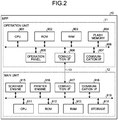
- FIG. 2 is a diagram illustrating an example of a hardware configuration of the MFP according to the first embodiment. With reference to FIG. 2 , the following describes the hardware configuration of the MFP 10 according to the present embodiment.
- the MFP 10 includes an operation unit 11 that receives a user's operation, and a main unit 12 that implements various image forming functions such as a scanner function and a printer function.
- “receive a user's operation” includes receiving information (including a signal indicating a coordinate value on a screen) that is input through a user's operation.
- the operation unit 11 and the main unit 12 are connected to each other in a communicable manner via a dedicated communication channel 13.
- a communication channel 13 for example, a communication channel of a Universal Serial Bus (USB) standard can be used, but the embodiment is not limited thereto.
- a communication channel of an optional standard may be used irrespective of a wired type or a wireless type.
- the main unit 12 performs an operation corresponding to the operation received by the operation unit 11.
- the operation unit 11 and the main unit 12 can communicate with an external device, and can perform an operation corresponding to an instruction received from the external device.
- the operation unit 11 includes a central processing unit (CPU) 901, a read only memory (ROM) 902, a random access memory (RAM) 903, a flash memory 904, an operation panel 905 (an example of an input unit), a connection I/F 906, a communication I/F 907, and a bus 908.
- CPU central processing unit
- ROM read only memory
- RAM random access memory
- flash memory 904 an example of an input unit
- connection I/F 906 a communication I/F 907
- bus 908 a bus 908
- the CPU 901 is an arithmetic device that integrally controls the operation of the operation unit 11.
- the CPU 901 controls the operation of the entire operation unit 11 by executing a computer program stored in the ROM 902, the flash memory 904, or the like using the RAM 903 as a work area (working area).
- the CPU 901 implements various functions such as causing information (an image) corresponding to an input received from the user to be displayed on the operation panel 905.
- the ROM 902 is, for example, a non-volatile memory that stores a Basic Input/Output System (BIOS) that is executed at the time of start of the operation unit 11, various settings.
- the RAM 903 is a volatile memory that is used as a work area for the CPU 901.
- the flash memory 904 is, for example, a non-volatile storage device that stores an OS, an application program, and various kinds of data.
- the operation panel 905 is a device having an input function and a display function that receives various inputs corresponding to the operation performed by the user, and displays various kinds of information (for example, information corresponding to the received operation, information representing an operation condition of the MFP 10, setting information).
- the operation panel 905 is, for example, constituted of a liquid crystal display (LCD) on which a touch panel function is mounted.
- the operation panel 905 is not limited to the liquid crystal display, and may be constituted of an organic electro-luminescence (EL) display device on which a touch panel function is mounted, for example.
- an operation unit such as a hardware key, or a display unit such as a lamp may be disposed on the operation panel 905.
- connection I/F 906 is an interface for communicating with the main unit 12 via the communication channel 13.
- the communication I/F 907 is a network interface for connecting the operation unit 11 to the network N to communicate with an external device connected to the network N.
- the communication I/F 907 is, for example, an interface that is compatible with Ethernet (registered trademark), and can perform communication conforming to Transmission Control Protocol (TCP)/Internet Protocol (IP).
- TCP Transmission Control Protocol
- IP Internet Protocol
- the bus 908 serves as a transmission line that connects the constituent elements described above to each other, and transmits an address signal, a data signal, and various kinds of control signals.
- the hardware configuration of the operation unit 11 illustrated in FIG. 2 is merely an example, and may include a constituent element other than the constituent elements illustrated in FIG. 2 .
- the main unit 12 includes a CPU 911, a ROM 912, a RAM 913, a storage 914 (an example of a storage), a scanner engine 915, a printer engine 916, a connection I/F 917, a communication I/F 918, and a bus 919.
- the CPU 911 is an arithmetic device that integrally controls an operation of the main unit 12.
- the CPU 911 controls the operation of the entire main unit 12 by executing a computer program stored in the ROM 912, the storage 914, or the like using the RAM 913 as a work area (working area).
- the CPU 911 implements various functions such as a copying function, a scanner function, a facsimile function, and a printer function.
- the ROM 912 is, for example, a non-volatile memory that stores a BIOS that is executed at the time of starting the main unit 12, and various settings.
- the RAM 913 is a volatile memory used as a work area of the CPU 911.
- the storage 914 is, for example, a non-volatile storage device that stores an OS, an application program, and various kinds of data.
- the storage 914 is, for example, constituted of a hard disk drive (HDD), a Solid State Drive (SSD), or the like.
- the scanner engine 915 is hardware that performs versatile information processing and processing other than communication for implementing a scanner function of scanning a document to be read as an image of the image forming function.
- the printer engine 916 is hardware that performs versatile information processing and processing other than communication for implementing a printer function of performing printing on a printing medium such as a sheet of the image forming function.
- connection I/F 917 is an interface for communicating with the operation unit 11 via the communication channel 13.
- the communication I/F 918 is a network interface for connecting the main unit 12 to the network N to communicate with an external device connected to the network N.
- the communication I/F 918 is, for example, an interface that is compatible with Ethernet, and can perform communication conforming to TCP/IP.
- the bus 919 is a transmission line that connects the constituent elements described above to each other, and transmits an address signal, a data signal, and various kinds of control signals.
- the hardware configuration of the main unit 12 illustrated in FIG. 2 is merely an example, and may include a constituent element other than the constituent elements illustrated in FIG. 2 .
- the hardware configuration may include a specific option such as a finisher that sorts printing media on which printing has been performed, or an auto document feeder (ADF) that automatically feeds a document.
- ADF auto document feeder
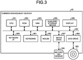
- FIG. 3 is a diagram illustrating an example of a hardware configuration of the common management server according to the first embodiment. With reference to FIG. 3 , the following describes the hardware configuration of the common management server 40 according to the present embodiment.
- the common management server 40 includes a CPU 951, a ROM 952, a RAM 953, an auxiliary storage device 955, a media drive 957, a display 958, a network I/F 959, a keyboard 961, a mouse 962, and a digital versatile disc (DVD) drive 964.
- a CPU 951 a ROM 952, a RAM 953, an auxiliary storage device 955, a media drive 957, a display 958, a network I/F 959, a keyboard 961, a mouse 962, and a digital versatile disc (DVD) drive 964.
- the CPU 951 is an arithmetic device that controls the operation of the entire common management server 40.
- the ROM 952 is a non-volatile storage device that stores a computer program for the common management server 40.
- the RAM 953 is a volatile storage device used as a work area of the CPU 951.
- the auxiliary storage device 955 is a storage device such as an HDD or an SSD that stores management information of a tenant, management information of a license, and management information of an account.
- the media drive 957 is a device that controls readout and writing of data for a recording medium 956 such as a flash memory under control by the CPU 951.
- the display 958 is a display device constituted of a liquid crystal, organic EL, or the like that displays various kinds of information such as a cursor, a menu, a window, a character, an image, or the like.
- the network I/F 959 is an interface for communicating data with an external device such as the contract management server 30 by using the network N.
- the network I/F 959 is, for example, a network interface card (NIC) that is compatible with Ethernet, and can perform communication conforming to TCP/IP.
- NIC network interface card
- the keyboard 961 is an input device for selecting a character, a numeral, and various instructions, and moving a cursor, for example.
- the mouse 962 is an input device for selecting and executing various instructions, selecting a processing target, and moving a cursor, for example.
- the DVD drive 964 is a device that controls readout and writing of data for a DVD 963 such as a DVD-ROM or a Digital Versatile Disk Recordable (DVD-R) as an example of a removable storage medium.
- a DVD 963 such as a DVD-ROM or a Digital Versatile Disk Recordable (DVD-R) as an example of a removable storage medium.
- DVD-R Digital Versatile Disk Recordable
- the CPU 951, the ROM 952, the RAM 953, the auxiliary storage device 955, the media drive 957, the display 958, the network I/F 959, the keyboard 961, the mouse 962, and the DVD drive 964 described above are connected to each other in a communicable manner via a bus line 960 such as an address bus and a data bus.
- a bus line 960 such as an address bus and a data bus.
- the hardware configuration of the common management server 40 illustrated in FIG. 3 is merely an example, and does not necessarily include all of the constituent elements illustrated in FIG. 3 , or may include another constituent element.
- the hardware configuration illustrated in FIG. 3 has been described as the hardware configuration of the common management server 40, but hardware configurations of the device management server 20, the contract management server 30, the application market server 50, the application management server 60, the firmware management server 70, and the PC 80 are equivalent to the hardware configuration illustrated in FIG. 3 .
- FIG. 4 is a diagram illustrating an example of a software configuration of the appliance management system according to the first embodiment. With reference to FIG. 4 , the following describes the software configuration of the appliance management system 1 according to the present embodiment.
- the operation unit 11 of the MFP 10 includes a setup Web application 14, a setup native application 15, a job log transmission application 16, an appliance management application 17, an authentication application 18, an application market application 19, a server service 21, a browser 22, and an installer 23.
- the setup Web application 14 serves to perform, cooperating with the setup native application 15, registration of appliance for associating the information processing device such as the MFP 10 with the tenant information of the common management server 40 to receive a cloud service, installation control of an application required at the time of introduction by the appliance registration, setting processing of a setting value (setting value of the application) to be set to the information processing device such as the MFP 10 for executing principal processing of the application.
- the following Table 1 lists examples of setting values for applications for use in introduction by the appliance registration in the common management server 40. "At the time of introduction by the appliance registration of the information processing device" indicates the time at which the cloud service is introduced into the information processing device to be started, for example.
- Introduction and start of use of the cloud service in the information processing device indicate a series of necessary processing at the time of introduction from no connection of the cloud to actual start of the information processing device to use at least part of the cloud service, the series of processing including appliance registration of the information processing device for a tenant to which the appliance belongs in the cloud service, confirmation of a service contracted by the tenant to which the appliance belongs (a package application, an individual application, and license information), and start of use of part of the cloud service.
- Part of the cloud service refers to a service provided by an application at the time of introduction (described later) in cooperation with each server, for example, an appliance management service provided by the device management server 20 or an authentication management service provided by the common management server 40.
- the cloud service examples include services provided by the function of the information processing device in cooperation with the function of the cloud such as cloud print (pull print by a remote MFP) and a scan to cloud storage (scanned image transmission). These services are usable on the appliance after the introduction by the appliance registration of the information processing device to the tenant information. Additionally, the cloud service also includes execution of a purchase contract of an application that is provided by the cloud service and used on the information processing device or the PC 80, and using the application after purchase contract on the information processing device or the PC 80.
- the setup native application 15 is a native application that performs, in cooperation with the setup Web application 14, appliance registration of the information processing device such as the MFP 10 in the common management server 40, installation control of the application required at the time of introduction by the appliance registration, and sets the setting value of the application, to receive the cloud service.
- the setup Web application 14 and the setup native application 15 that perform appliance registration in the common management server 40, installation control of the application required at the time of introduction by the appliance registration, and setting processing of the setting value of the application may be collectively referred to as a "setup application".
- the setup application includes the native application and the Web application. Introduction may be executed by the setup application including either the native application or the Web application alone.
- the job log transmission application 16 is an example of the application to be installed at the time of introduction by the appliance registration of the information processing device such as the MFP 10 for the common management server 40, and is an application that collects job logs generated in the information processing device such as the MFP 10 to be transmitted to the device management server 20. Examples of the setting values for the job log transmission application 16 are indicated by Table 1.
- items of the setting values for the job log transmission application 16 include "log operation mode”, “log transfer/transfer setting timing”, and "job log collection”, and setting is established corresponding to the setting items and values in Table 1 such that all job logs executed by the information processing device (log operation mode: 4) are automatically generated in accordance with job execution (job log collection: ON), and the job logs are transmitted to a given external server each time the job log is generated (transmission timing: 1). Accordingly, the setting for log collection and transmission performed by the job log transmission application 16 can be established in the information processing device. As the external server, the device management server 20 is set in the job log transmission application 16. The Web application providing the appliance management service in the device management server 20 acquires the job log, and associates the job log with the tenant information and appliance information belonging thereto to be stored.
- the appliance management application 17 is an example of an application to be installed at the time of introduction by the appliance registration of the information processing device such as the MFP 10 for the common management server 40, and is an application that transmits, to the device management server 20, the appliance information, the setting values of the MFP 10 (authentication ON, job log collection ON, and an IP address and a host name set to the appliance), and an appliance status (state of consumables, an error state, and an energy-saving transition state).
- Table 1 above does not contain setting values used in execution of processing by the appliance management application 17.
- setting data of the appliance management application 17 can be settings that enable transmission of setting values and application status to the external server, for example.
- the authentication application 18 is an example of an application to be installed at the time of introduction by the appliance registration of the information processing device such as the MFP 10 for the common management server 40, and is an application for authenticating a login of the information processing device such as the MFP 10 using an authentication result obtained outside the device by an account (account of the cloud) managed by the common management server 40 by transmitting user information input via the MFP 10 to the common management server 40.
- Examples of the setting values for the authentication application 18 are indicated by Table 1.
- items of the setting values for the authentication application 18 include "user administrator authentication”, “user authentication management”, and “user automatic deletion”, and setting is established corresponding to the setting items and values in Table 1 described above such that a login of the information processing device is authenticated (user authentication management: custom authentication, and user administrator authentication: Yes) by using an authentication application added (customized) to the information processing device, transmitting the acquired user information to an authentication destination (common management server 40) set by the authentication application to perform authentication processing at the authentication destination, and obtaining an authentication result.
- an authentication destination common management server 40
- the setting value of "user administrator authentication: Yes" may be a setting such that, in a case in which the user is the tenant administrator as a result of authentication performed by the common management server 40, a login of the information processing device as the administrator of the appliance is authenticated (user administrator authentication: Yes), and in a case in which administrator authentication has succeeded, an administrator function in the information processing device (permission for address book editing or manual change of the setting value) is allowed to be used.
- the information processing device includes a function by which the user information authenticated by the common management server 40 as the authentication destination is automatically and successively stored in a storage region (an address book) in the information processing device.
- An additional setting can be established such that, at the time when a storage amount of the user information in the address book reaches a given amount, information that is assumed to be unused such as the oldest user information (or user information on which authentication processing has not been performed for a given period) is deleted, and the user information authenticated by the common management server 40 is newly added to the information processing device (user automatic deletion: Yes).
- the setting of "user automatic deletion: Yes" may be a setting such that, after the authentication processing of the user information performed by the common management server 40 as the authentication destination, the acquired user information is automatically deleted from the information processing device (a cache of a browser function for transmitting the user information by the authentication application) irrespective of an authentication result.
- the setting of the authentication application 18 for performing the authentication processing cooperating with the common management server 40 can be established in the information processing device.
- the item names and values in the setting of Table 1 described above are held by each introduction application as setting data, which is information written in a setting file of object data of the application being the native application.
- the value to be set at the time of setting cancellation in Table 1 is referred to, and set for the information processing device.
- Each introduction application refers to the setting value set for the information processing device after being started or at the time of performing processing, and performs processing of each introduction application based on the setting value.
- the application market application 19 is an application that communicates with an application market site provided by the application market server 50, and acquires a list of applications and firmware that can be installed in the information processing device such as the MFP 10 in accordance with an operation performed by the user.
- the server service 21 is a service that provides a function of a Web server that operates on the operation unit 11, and relays exchange of information with the application market application 19.
- the browser 22 is software that implements a function as a Web application by acquiring various pieces of content provided by the Web server (for example, HyperText Markup Language (HTML), Cascading Style Sheets (CSS), JavaScript (registered trademark), and various electronic files).
- the browser 22 generates a shortcut icon of the Web application in accordance with a command from the application market application 19.
- the installer 23 is a module that downloads an entity file (object file) of the native application or firmware from the application management server 60 or the firmware management server 70 in accordance with a command from the application market application 19, and installs the entity file in the operation unit 11.
- the main unit 12 of the MFP 10 includes a communication module 24, a main authentication module 25, and a log generation module 26.
- the communication module 24 is a module that relays data communication between an application and module of the operation unit 11 and a module of the main unit 12.
- the main authentication module 25 is a module that performs authentication control for the main unit 12 by communication via the authentication application 18 and the communication module 24.
- the log generation module 26 is a module that generates an operation log of a function operating on the main unit 12, and transmitting the operation log to the job log transmission application 16 via the communication module 24.
- the PC 80 includes a utility 81.
- the utility 81 is software that remotely performs control for installation of applications and setting processing of the setting values by batch for the information processing device such as the MFP 10.
- each piece of software illustrated in FIG. 4 is merely an example, and the configuration is not limited thereto.
- a plurality of pieces of software as independent pieces of software in the operation unit 11 illustrated in FIG. 4 may be configured as one piece of software.
- a function of one piece of software in the operation unit 11 illustrated in FIG. 4 may be divided into a plurality of functions, and may be configured as a plurality of pieces of software.
- FIG. 5 is a diagram illustrating an example of a configuration of a functional block of the appliance management system according to the first embodiment. With reference to FIG. 5 , the following describes a configuration and an operation of the functional block of the appliance management system 1 according to the present embodiment.
- the operation unit 11 of the MFP 10 includes a communicator 101, an appliance information acquirer 102 (a first acquirer), an appliance registration requester 103, an installed application list acquirer 104, a setting controller 105, a license checker 110 (a determiner, a third acquirer), an installation target application list acquirer 111 (a fourth acquirer), an installation controller 112, an installer 113, an icon generator 114 (generator), a display controller 115 (a first display controller, a second display controller), and a storage 116.
- the communicator 101 is a functional unit that performs data communication with the device management server 20, the common management server 40, the application market server 50, the application management server 60, and the firmware management server 70 via the network N.
- the communicator 101 is implemented when the communication I/F 907 and the CPU 901 illustrated in FIG. 2 execute a computer program (the server service 21).
- the appliance information acquirer 102 is a functional unit that acquires appliance information (including a serial number (an example of identification information) of the MFP 10) of the main unit 12 from a main controller 121.
- the appliance information acquirer 102 is implemented when the CPU 901 illustrated in FIG. 2 executes a computer program (the setup Web application 14, the setup native application 15).
- the appliance registration requester 103 is a functional unit that transmits, to the common management server 40, an appliance registration request including a tenant ID (an example of tenant information), an administrator ID, and a password input via the operation panel 905 together with the appliance information acquired by the appliance information acquirer 102 via the communicator 101.
- the appliance registration requester 103 is implemented when the CPU 901 illustrated in FIG. 2 executes a computer program (the setup Web application 14).
- the installed application list acquirer 104 is a functional unit that acquires a list of applications that have been already installed in the operation unit 11 (a list of identification information of the applications) from the installer 23 via the browser 22.
- the installed application list acquirer 104 is implemented when the CPU 901 illustrated in FIG. 2 executes a computer program (the setup Web application 14, the setup native application 15, the browser 22, the installer 23).
- the setting controller 105 is a functional unit that controls setting processing of the setting value related to the application that has been installed at the time of introduction by appliance registration of the information processing device such as the MFP 10 for the common management server 40. As illustrated in FIG. 5 , the setting controller 105 includes a target searcher 106, a setting value list acquirer 107 (a second acquirer), a set value reader 108, and a setting value writer 109 (writer). The setting controller 105 is implemented by a computer program (the setup native application 15, for example) executed by the CPU 901 illustrated in FIG. 2 .
- the target searcher 106 is a functional unit that searches for an application as a setting target of the setting value, that is, a licensed application among applications that are installed at the time of introduction by appliance registration of the information processing device such as the MFP 10 for the common management server 40 (hereinafter, may be referred to as "an introduction application"). Specifically, the target searcher 106 searches for an application as a setting target of the setting value that has been licensed.
- the setting value list acquirer 107 is a functional unit that acquires setting data defining a list of setting values in extensible markup language (XML) format, for example, included in the introduction application (for example, the job log transmission application 16, the appliance management application 17, and the authentication application 18).
- XML extensible markup language
- the setting data or the setting value may be acquired by making a request to the Web application.
- the set value reader 108 is a functional unit that reads the value set to the introduction application from the main unit 12.
- the setting value writer 109 is a functional unit that writes, to the main unit 12, the setting data for use in processing the introduction application acquired by the setting value list acquirer 107 as the setting value.
- the license checker 110 is a functional unit that checks whether a license contract is made for the introduction application with respect to the common management server 40.
- the license checker 110 is implemented when the CPU 901 illustrated in FIG. 2 executes a computer program (the setup native application 15).
- the license checker 110 may also be implemented when the CPU 901 executes the setup Web application 14.
- the installation target application list acquirer 111 is a functional unit that acquires, from the application market server 50, a list of applications (a list of identification information of the applications) to be installed at the time of introduction by appliance registration of the information processing device such as the MFP 10 for the common management server 40.
- the installation target application list acquirer 111 is implemented when the CPU 901 illustrated in FIG. 2 executes a computer program (the application market application 19).
- the installation controller 112 is a functional unit that transmits an installation request for the introduction application to the installer 113 and the icon generator 114.
- the installation controller 112 is implemented when the CPU 901 illustrated in FIG. 2 executes a computer program (the setup Web application 14, the application market application 19).
- the installer 113 is a functional unit that receives, when receiving the installation request for the native application among the introduction applications from the installation controller 112, an entity file (object file) of the native application from the application management server 60, and installs the native application using the entity file.
- the installer 113 is implemented when the CPU 901 illustrated in FIG. 2 executes a computer program (the installer 23).
- the icon generator 114 is a functional unit that generates, when receiving an installation request for the Web application among the introduction applications from the installation controller 112, a shortcut icon for designating a path including an execution file of the Web application.
- the icon generator 114 is implemented when the CPU 901 illustrated in FIG. 2 executes a computer program (the browser 22).
- the display controller 115 is a functional unit that performs display control for various screens such as an application list screen, an application installation screen, a tenant login screen, and a batch setting screen.
- the display controller 115 is implemented when the CPU 901 illustrated in FIG. 2 executes a computer program (the browser 22, the setup Web application 14, the setup native application 15).
- the storage 116 is a functional unit that stores various kinds of data such as setting values for various applications.
- the storage 116 is implemented by at least one of the RAM 903 and the flash memory 904 illustrated in FIG. 2 .
- the main unit 12 of the MFP 10 includes a main controller 121.
- the main controller 121 is a functional unit that acquires the appliance information including the serial number of the MFP 10 from the main unit 12.
- the main controller 121 is implemented when the CPU 911 illustrated in FIG. 2 executes a computer program.
- Some or all of the appliance information acquirer 102, the appliance registration requester 103, the installed application list acquirer 104, the setting controller 105, the license checker 110, the installation target application list acquirer 111, the installation controller 112, the installer 113, the icon generator 114, the display controller 115, and the main controller 121 of the MFP 10 illustrated in FIG. 5 may be implemented by a hardware circuit such as a field-programmable gate array (FPGA) or an application specific integrated circuit (ASIC) instead of a computer program as software.
- FPGA field-programmable gate array
- ASIC application specific integrated circuit
- the common management server 40 includes a communicator 401, a tenant registration unit 402, an appliance registration unit 403, a license information acquirer 404, and the storage 405.
- the communicator 401 is a functional unit that performs data communication with the MFP 10, the device management server 20, and the contract management server 30 via the network N.
- the communicator 401 is implemented when the network I/F 959 and the CPU 951 illustrated in FIG. 3 execute a computer program.
- the tenant registration unit 402 is a functional unit that registers the tenant ID for identifying the tenant to which the MFP 10 belongs.
- the tenant registration unit 402 causes the tenant ID to be stored in the storage 405 to be registered.
- the tenant registration unit 402 is implemented when the CPU 951 illustrated in FIG. 3 executes a computer program.
- the appliance registration unit 403 is a functional unit that searches for, in accordance with the appliance registration request from the MFP 10, a tenant ID matching the tenant ID for identifying the tenant included in the appliance registration request from tenant IDs registered by the tenant registration unit 402, and associates the searched tenant ID with the information (serial number) for identifying the MFP 10 as the appliance information to perform appliance registration.
- the appliance registration unit 403 causes the storage 405 to store the information associating the tenant ID with the serial number.
- the appliance registration unit 403 is implemented when the CPU 951 illustrated in FIG. 3 executes a computer program.
- the license information acquirer 404 is a functional unit that acquires license information representing the fact that the introduction application is licensed in accordance with a license information search request from the MFP 10.
- the license information acquirer 404 is implemented when the CPU 951 illustrated in FIG. 3 executes a computer program.
- the storage 405 is a functional unit that stores various kinds of information such as information registered in the appliance by the appliance registration unit 403.
- the storage 405 is implemented by the auxiliary storage device 955 illustrated in FIG. 3 .
- Some or all of the tenant registration unit 402, the appliance registration unit 403, and the license information acquirer 404 of the common management server 40 illustrated in FIG. 5 may be implemented by a hardware circuit such as an FPGA or an ASIC instead of a computer program as software.
- the application market server 50 includes a communicator 501, an application information transmitter 502, and a storage 503.
- the communicator 501 is a functional unit that performs data communication with the MFP 10 via the network N.
- the communicator 501 is implemented when the network I/F 959 and the CPU 951 illustrated in FIG. 3 execute a computer program.
- the application information transmitter 502 is a functional unit that transmits, to the MFP 10, a list of applications as installation target at the time of introduction by appliance registration of the MFP 10 for the common management server 40 via the communicator 501 in accordance with an installation target application list acquisition request from the MFP 10.
- the application information transmitter 502 is implemented when the CPU 951 illustrated in FIG. 3 executes a computer program.
- the storage 503 is a functional unit that stores information related to the application and the firmware that can be installed in the information processing device such as the MFP 10.
- the storage 503 is implemented by the auxiliary storage device 955 illustrated in FIG. 3 .
- the application information transmitter 502 of the application market server 50 illustrated in FIG. 5 may be implemented by a hardware circuit such as an FPGA or an ASIC instead of a computer program as software.
- the PC 80 includes a communicator 801, a target appliance searcher 802 (appliance searcher), an appliance information acquirer 803 (a fifth acquirer), an appliance registration requester 804, and a display controller 805.
- the communicator 801 is a functional unit that performs data communication with the MFP 10 via the network N.
- the communicator 801 is implemented when the network I/F 959 and the CPU 951 illustrated in FIG. 3 execute a computer program.
- the target appliance searcher 802 is a functional unit that searches for an information processing device included in an IP address range of the target appliance of installation of the applications and setting processing of the setting values designated by an operation input to the keyboard 961 and the mouse 962.
- the target appliance searcher 802 is implemented when the CPU 951 illustrated in FIG. 3 executes a computer program (the utility 81).
- the appliance information acquirer 803 is a functional unit that acquires the appliance information including the serial number (an example of identification information) from the information processing device as the target appliance of installation of the applications and the setting processing of the setting values found by the target appliance searcher 802.
- the appliance information acquirer 803 is implemented when the CPU 951 illustrated in FIG. 3 executes a computer program (the utility 81).
- the appliance registration requester 804 is a functional unit that transmits the appliance registration request including the tenant ID (an example of tenant information), the administrator ID, and the password input via the keyboard 961 and the mouse 962 to the common management server 40 via the communicator 801 together with the appliance information acquired by the appliance information acquirer 803.
- the appliance registration requester 804 is implemented when the CPU 951 illustrated in FIG. 3 executes a computer program (the utility 81).
- the display controller 805 is a functional unit that performs display control for various screens displayed on the display 958.
- the display controller 805 is implemented when the CPU 951 illustrated in FIG. 3 executes a computer program (the utility 81).
- Some or all of the target appliance searcher 802, the appliance information acquirer 803, and the appliance registration requester 804 of the PC 80 illustrated in FIG. 5 may be implemented by a hardware circuit such as an FPGA or an ASIC instead of a computer program as software.
- the respective functional units of the MFP 10, the common management server 40, the application market server 50, and the PC 80 illustrated in FIG. 5 are merely conceptual, and are not limited to the configurations described above.
- the functional units illustrated as independent functional units of the MFP 10, the common management server 40, the application market server 50, and the PC 80 illustrated in FIG. 5 may be configured as one functional unit.
- the function of one functional unit of the MFP 10, the common management server 40, the application market server 50, and the PC 80 illustrated in FIG. 5 may be divided into a plurality of functions, and may be configured as a plurality of functional units.
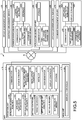
- FIG. 6A and FIG. 6B are sequence diagrams illustrating an example of a procedure of installation and batch setting in a case in which the setup application is not installed in the appliance management system according to the first embodiment.
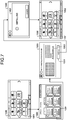
- FIG. 7 is a diagram illustrating a flow of screen transition at the time of installing the application in the installation and batch setting in a case in which the setup application is not installed in the appliance management system according to the first embodiment.
- FIG. 8 is a diagram illustrating a flow of screen transition at the time of registering the appliance in the installation and batch setting in a case in which the setup application is not installed in the appliance management system according to the first embodiment.
- FIG. 7 is a diagram illustrating a flow of screen transition at the time of installing the application in the installation and batch setting in a case in which the setup application is not installed in the appliance management system according to the first embodiment.
- FIG. 8 is a diagram illustrating a flow of screen transition at the time of registering the appliance in the installation and batch setting in a case in which the setup application is not installed in the
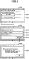
- FIG. 9 is a diagram illustrating a flow of screen transition at the time of batch setting in the installation and batch setting in a case in which the setup application is not installed in the appliance management system according to the first embodiment.
- FIG. 10 is a diagram illustrating another example of the tenant login screen.
- FIG. 6A and FIG. 6B may be collectively referred to as FIG. 6 .
- the following describes the procedure of installation and batch setting when the setup application is not installed in the appliance management system 1 according to the present embodiment.
- a sales representative who makes a contract for introducing a cloud service using the common management server 40 for a tenant as an organization that utilizes the MFP 10 perform registration work for the tenant on the common management server 40.
- the tenant registration unit 402 of the common management server 40 registers, in the storage 405, the tenant ID for identifying the tenant to which the MFP 10 belongs in accordance with the registration work for the tenant performed by the sales representative, for example.
- the tenant registration unit 402 registers the tenant ID, issues the administrator ID and the password, and notifies the tenant administrator of the tenant ID, the administrator ID, and the password using a given method (e-mail notification).
- the common management server 40 creates, in the storage 405 of the common management server 40, a storage region for storing and accumulating various kinds of information as a management target of the tenant such as user information, appliance information, and license information (described later) to be associated with the tenant information (tenant ID) of the tenant. Furthermore, along with the registration of the tenant, the common management server 40 generates, in a storage region of the device management server 20, a storage region for storing and accumulating appliance information and appliance output information for each piece of the appliance information (log information and setting value information for each information processing device) to be associated with the tenant information (tenant ID).
- the common management server 40 and the device management server 20 respectively include Web applications cooperating and linking with each other.
- the user and the tenant administrator can view various kinds of information associated with the tenant ID, make a setting, and make a processing execution request by displaying and logging in each Web application (Web site) using a Web browser of the terminal device such as the PC 80.
- the tenant may include various kinds of information associated with the tenant information, the storage region of the information, and the Web application for viewing information or making various settings (appliance registration, user registration, licensing) in addition to the tenant ID and the tenant name issued by a service person of a sales company in a certain country to the organization that utilizes the cloud service.
- the display controller 115 By an operation input to the operation panel 905 of the MFP 10 performed by the tenant administrator, the display controller 115 causes the operation panel 905 to display a home screen 1000 illustrated in FIG. 7 .
- the display controller 115 causes the operation panel 905 to display a list screen 1200 indicating a list of a plurality of applications and pieces of firmware that can be installed in the MFP 10.
- the list screen 1200 is a screen that displays a list of a plurality of applications and pieces of firmware that can be installed in the MFP 10, and displays the list as a button icon for installing each of the applications and a button icon for installing each of the pieces of firmware.
- the applications displayed as button icons include a group application (an installation package. An application package including one or more applications) with which a plurality of applications can be collectively and successively installed using one button icon, and batch installation (described later) is performed by this mechanism.
- the list screen 1200 includes a batch installation package button 1201 for installing applications (introduction applications) to be installed at the time of introduction by appliance registration of the information processing device such as the MFP 10 for the common management server 40 by batch.
- the display controller 115 causes the operation panel 905 to display an installation screen 1300 for installing the introduction application.
- the installation screen 1300 is a screen for installing the introduction applications by batch, and includes an installation button 1301 for executing installation of the introduction applications, and package details 1303.
- the installation controller 112 which is implemented by the CPU 901's executing the setup Web application 14 and the application market application 19 of the MFP 10, transmits an installation request for the Web application among the introduction applications (Web application installation request) to the icon generator 114.
- the Web application installation request includes icon information of the Web application, a title of the Web application, and a uniform resource locator (URL) indicating a place where the execution file of the Web application is stored.
- URL uniform resource locator
- a functional unit that is implemented when the CPU executes a specific computer program may be represented as a "functional unit of a specific computer program" in some cases.
- the setup Web application 14 transmits an installation notification to the application market application 19.
- the application market application 19 then transmits the Web application installation request described above to the browser 22.
- the icon generator 114 of the browser 22 After receiving the Web application installation request from the installation controller 112, the icon generator 114 of the browser 22 generates a shortcut icon that designates a path including the execution file of the Web application, in accordance with the icon information, the title, and the URL included in the Web application installation request.
- the installation controller 112 transmits, to the installer 113 of the installer 23, an installation request for the native application among the introduction applications (a native application installation request).
- the native application installation request includes a product ID and a product key of the native application.
- the installer 113 of the installer 23 When receiving the native application installation request from the installation controller 112, the installer 113 of the installer 23 receives an entity file (object file) of the native application from the application management server 60 based on the product ID and the product key included in the native application installation request. The installer 113 installs the native application using the entity file.
- entity file object file
- the display controller 115 causes the operation panel 905 to display an installing dialog box 1400 indicating that the native application is being installed.
- the installer 113 then returns success or failure of the installation of the native application to the installation controller 112 of the application market application 19.
- the success or failure of the installation is transmitted from the application market application 19 to the setup Web application 14.
- the display controller 115 causes the operation panel 905 to display the home screen 1000 to which a setup icon 1002 is added, the setup icon 1002 for performing setting processing of setting values for the introduction application.
- the display controller 115 of the setup Web application 14 causes the operation panel 905 to display a tenant login screen 1500 for logging in based on the tenant ID.
- the tenant login screen 1500 is a screen for logging in the MFP 10 using the tenant ID, the administrator ID, and the password notified from the common management server 40. As illustrated in FIG. 8 , the tenant login screen 1500 includes a tenant ID input box 1501 for inputting the tenant ID, an administrator ID input box 1502 for inputting the administrator ID, a password input box 1503 for inputting the password, and a login button 1504 for executing a login.
- an e-mail address and a password may be respectively input to an e-mail address input box 1505 and the password input box 1503 on a tenant login screen 1500a illustrated in FIG. 10 .
- the e-mail address is assumed to correspond to the tenant ID and the administrator ID, and at Step S12 described above, information corresponding to the tenant ID may be registered based on the e-mail address of the tenant administrator, for example.
- the tenant administrator inputs the tenant ID, the administrator ID, and the password respectively to the tenant ID input box 1501, the administrator ID input box 1502, and the password input box 1503 on the tenant login screen 1500 via the operation panel 905.
- the tenant administrator then performs a touch operation on the login button 1504.
- the appliance information acquirer 102 of the setup Web application 14 then acquires appliance information of the main unit 12 (including the serial number of the MFP 10) from the main controller 121. Specifically, when the setup Web application 14 transmits the appliance information acquisition request to the setup native application 15, and the setup native application 15 acquires the appliance information from the main unit 12, the appliance information is returned to the setup Web application 14.
- the appliance registration requester 103 of the setup Web application 14 transmits the appliance registration request including the tenant ID, the administrator ID, and the password input via the operation panel 905 to the common management server 40 together with the appliance information acquired by the appliance information acquirer 102 via the communicator 101.
- the appliance registration unit 403 of the common management server 40 When receiving the appliance registration request from the MFP 10 via the communicator 401, the appliance registration unit 403 of the common management server 40 performs authentication using the administrator ID and the password included in the appliance registration request. If authentication is normally performed, the appliance registration unit 403 searches tenant IDs registered by the tenant registration unit 402 for a tenant ID matching the tenant ID for identifying the tenant included in the appliance registration request, and associates the found tenant ID with the information (serial number) for identifying the MFP 10 as the appliance information to perform appliance registration. The appliance registration unit 403 causes the storage 405 to store information associating the tenant ID with the serial number.
- the appliance registration unit 403 then transmits an authentication ticket issued by the authentication described above to the MFP 10 via the communicator 401.
- the installed application list acquirer 104 of the operation unit 11 acquires a list of applications that have been already installed in the operation unit 11 (a list of the identification information of the applications) based on the authentication ticket.
- the setup Web application 14 transmits the installed application list acquisition request to the browser 22, and the browser 22 transmits the installed application list acquisition request to the installer 23.
- the installer 23 acquires the list of the applications that have been already installed in the operation unit 11, and transmits the list to the browser 22.
- the browser 22 transmits the installed application list received from the installer 23 to the setup Web application 14.
- the display controller 115 of the setup Web application 14 causes the operation panel 905 to display a batch setting screen 1600 illustrated in FIG. 9 .
- the batch setting screen 1600 is a screen for performing setting processing of the setting values related to installed introduction application by batch.
- the batch setting screen 1600 includes a batch setting button 1601 for performing batch setting of the setting values, and a batch setting cancellation button 1602 for canceling the set setting values by batch.
- the installation controller 112 of the setup Web application 14 transmits a batch setting request having an identifier of "manual” and a request type of "setting" to the license checker 110 of the setup native application 15.
- the license checker 110 of the setup native application 15 transmits a license information search request for checking presence/absence of a license for the installed introduction application to the common management server 40 via the communicator 101.
- the license information acquirer 404 of the common management server 40 acquires license information representing whether the introduction application has been licensed.
- the license information acquirer 404 transmits the acquired license information to the MFP 10 via the communicator 401.
- the license information is information for certifying purchase, a subscription, or a contract for the application by the tenant administrator for each tenant, and includes information representing the number of appliances and the number of users who can use the contracted application.
- the license information search request is issued for checking the license information currently permitted for the information processing device 10 by transmitting, to the common management server 40 from the information processing device 10, the authentication ticket and machine number information issued from the common management server 40 and acquired by the information processing device 10.
- the target searcher 106 of the setting controller 105 of the setup native application 15 searches for a licensed application from among the installed introduction applications based on the license information.
- the display controller 115 of the setup native application 15 causes the operation panel 905 to display a message, a screen, or the like for warning that there is no application under a license contract.
- the setting value list acquirer 107 of the setting controller 105 of the setup native application 15 searches for whether the introduction application includes setting data (or whether the setting data of the introduction application includes a setting value that should be set) via an operation unit OS 11a as an operating system (OS) of the operation unit 11 regarding the setting data (setting file) defining a list of setting values in an extensible Markup Language (XML) format, for example, included in the introduction application (for example, the job log transmission application 16, the appliance management application 17, and the authentication application 18), and acquires the found setting data as a search result.
- XML extensible Markup Language
- the setting value list acquirer 107 may make a request for the setting data to the Web application via a network to acquire the setting data. Due to this, even if each introduction application has a setting value that should be set for the information processing device, the setting value for the information processing device is enabled to be rewritten by causing the introduction application to have the information thereof, so that time and effort for individually and manually changing the setting value can be saved.
- the setting controller 105 of the setup native application 15 analyzes content of the setting data acquired by the setting value list acquirer 107.
- the set value reader 108 of the setting controller 105 of the setup native application 15 reads out the current setting values of the application at the time of introduction, from the main unit 12 via the communication module 24.
- the display controller 115 of the setup native application 15 causes the operation panel 905 to display an administrator authentication screen 1610.
- the administrator authentication screen 1610 is a screen for performing administrator authentication by the administrator of the information processing device (different from the tenant administrator) that is required for writing the setting value into the main unit 12 independent of the administrator ID and the password described above notified from the common management server 40.
- the administrator authentication screen 1610 includes an administrator name input box 1611 for inputting an administrator name, a password input box 1612 for inputting a password, and a setting button 1613 for executing authentication setting.
- the tenant administrator inputs an administrator name and a password as the administrator authentication information respectively to the administrator name input box 1611 and the password input box 1612 on the administrator authentication screen 1610 via the operation panel 905, and performs a touch operation on the setting button 1613.
- the setting controller 105 (an example of an authenticator) of the setup native application 15 performs administrator authentication based on the input administrator name and password. With a failure of the administrator authentication, the process stops without execution of the following processing. In this way, the setting controller 105 performs authentication of the tenant administrator before batch setting (writing processing) to the setting values, to be able to perform the batch setting to the setting values under the supervision of the tenant administrator.
- the display controller 115 of the setup native application 15 causes the operation panel 905 to display a restart warning dialog box 1620 for warning that a restart may be performed when a new setting value is written.
- a restart warning dialog box 1620 for warning that a restart may be performed when a new setting value is written.
- the setting value writer 109 of the setting controller 105 of the setup native application 15 transmits a setting value writing request for writing the setting data acquired by the setting value list acquirer 107 as the setting value for the introduction application to the main unit 12 together with the setting data via the communication module 24.
- the main unit 12 When receiving the setting value writing request, the main unit 12 writes the setting value corresponding to the unset item in the setting data into the storage 914 to be updated. The main unit 12 then transmits a writing result of the setting value to the setting value writer 109 via the communication module 24.
- the display controller 115 of the setup native application 15 causes the operation panel 905 to display a message or a screen indicating that writing of the setting value failed.
- the setting controller 105 of the setup native application 15 restarts the MFP 10.
- the display controller 115 of the setup native application 15 causes the operation panel 905 to display a message or a screen indicating that the setting values have been already set for the introduction application.
- the information processing device such as the MFP 10 can be registered in the cloud (common management server 40) by appliance registration, and the setting values for the introduction application can be set by batch, so that the cloud service using the common management server 40 can be easily associated with the information processing device (appliance) such as the MFP 10, and time and effort for preparation for receiving provision of the cloud service can be reduced.
- FIG. 11 is a sequence diagram illustrating an example of a procedure of application start processing after the installation and batch setting in the appliance management system according to the first embodiment.
- the following describes the procedure of application start processing after the installation and batch setting in the appliance management system 1 according to the present embodiment.
- the operation unit OS 11a of the operation unit 11 transmits a start command for automatically starting the introduction application.
- the following describes an operation of the job log transmission application 16 as the introduction application.
- the job log transmission application 16 automatically starts in accordance with the start command from the operation unit OS 11a.
- the job log transmission application 16 then starts to collect a log related to the operation of the main unit 12 generated by the log generation module 26 via the communication module 24.
- the job log transmission application 16 then transmits the collected log to the device management server 20.
- the device management server 20 When receiving the log from the job log transmission application 16, the device management server 20 checks whether the job log transmission application 16 is a licensed application. For example, the device management server 20 makes an inquiry to the common management server 40 whether the job log transmission application 16 is a licensed application.
- the device management server 20 When finding that the job log transmission application 16 is a licensed application, the device management server 20 stores the received log in the auxiliary storage device 955 of itself. The device management server 20 then returns, to the job log transmission application 16 of the MFP 10, an OK response indicating that the job log transmission application 16 is a licensed application and the log is completely stored.
- the device management server 20 When failing to find that the job log transmission application 16 is a licensed application, the device management server 20 discards the received log, and returns, to the job log transmission application 16 of the MFP 10, an NG (no good) response indicating that the job log transmission application 16 is not a licensed application. After receiving the NG response, the job log transmission application 16 determines that it is not appropriate to continue the operation since the application is not licensed, and stops the operation.
- the other introduction applications also automatically start in accordance with the start command from the operation unit OS 11a, and perform respective operations.
- FIG. 12 is a sequence diagram illustrating an example of a procedure of batch setting cancellation and uninstallation processing in the appliance management system according to the first embodiment.
- the following describes the procedure of batch setting cancellation and uninstallation processing in the appliance management system 1 according to the present embodiment. It is assumed that the installation and batch setting illustrated in FIG. 6 described above is performed before the batch setting cancellation and uninstallation processing illustrated in FIG. 12 is performed.
- the tenant administrator performs a touch operation on the setup icon 1002 on the home screen 1000 illustrated in FIG. 8 .
- the display controller 115 of the setup Web application 14 then causes the operation panel 905 to display the batch setting screen 1600 illustrated in FIG. 9 .
- the batch setting screen 1600 includes the batch setting cancellation button 1602 for canceling the set setting values by batch.
- the installation controller 112 of the setup Web application 14 transmits a batch setting cancellation request having the identifier of "manual” and the request type of "unsetting", and including a column of the product ID of the introduction application to the setting controller 105 of the setup native application 15.
- the setting value list acquirer 107 of the setting controller 105 of the setup native application 15 searches for setting data defining a list of the setting values in an XML format, for example, included in the introduction application via the operation unit OS 11a as the OS of the operation unit 11, and acquires the found setting data as a search result.
- the setting controller 105 of the setup native application 15 analyzes content of the setting data acquired by the setting value list acquirer 107.
- the set value reader 108 of the setting controller 105 of the setup native application 15 reads out the current setting values of the application at the time of introduction from the main unit 12 via the communication module 24.
- the display controller 115 of the setup native application 15 causes the operation panel 905 to display the administrator authentication screen 1610.
- the tenant administrator inputs the administrator name and the password as the administrator authentication information respectively to the administrator name input box 1611 and the password input box 1612 on the administrator authentication screen 1610 via the operation panel 905, and performs a touch operation on the setting button 1613.
- the setting controller 105 (an example of an authenticator) of the setup native application 15 performs administrator authentication based on the input administrator name and password. With a failure of the administrator authentication, the process stops without execution of the following processing. In this way, the setting controller 105 performs authentication of the tenant administrator before batch setting cancellation processing (writing processing) to the setting values, to be able to perform the batch setting cancellation processing to the setting values under supervision of the tenant administrator.
- the display controller 115 of the setup native application 15 causes the operation panel 905 to display the restart warning dialog box 1620 for warning that a restart may be performed when a new setting value is written.
- the setting value writer 109 of the setting controller 105 of the setup native application 15 transmits a setting value writing request for performing setting cancellation by writing the setting value that has been set at the time of introduction read out by the set value reader 108 at Step S47 illustrated in FIG. 6 to the main unit 12 together with the setting value via the communication module 24.
- the main unit 12 When receiving the setting value writing request, the main unit 12 writes the setting value corresponding to the not-canceled setting item among the setting values into the storage 914 to be updated.
- the main unit 12 then transmits a writing result of the setting value to the setting value writer 109 via the communication module 24.
- the display controller 115 of the setup native application 15 causes the operation panel 905 to display a message or a screen indicating that writing of the setting value failed.
- the setting controller 105 of the setup native application 15 restarts the MFP 10.
- the display controller 115 of the setup native application 15 causes the operation panel 905 to display a setting cancellation completion screen indicating that setting cancellation has been already performed on the setting values for the introduction application.
- the tenant administrator then performs an operation on the operation panel 905 to uninstall the introduction application from the home screen 1000 and the list screen 1200 illustrated in FIG. 7 .
- FIG. 13A and FIG. 13B are sequence diagrams illustrating an example of a procedure of manual installation and batch setting when the setup application is installed in the appliance management system according to the first embodiment.
- FIG. 14 is a diagram illustrating a flow of screen transition at the time of installation and batch setting of the application during the installation and batch setting process when the setup application is installed in the appliance management system according to the first embodiment.
- FIG. 13A and FIG. 13B may be collectively referred to as FIG. 13 .
- the following describes the procedure of manual installation and batch setting in a case in which the setup application is installed in the appliance management system 1 according to the present embodiment.
- the pieces of processing at Steps Sill to S113 are the same as the respective pieces of processing at Steps S11 to S13 illustrated in FIG. 6 .
- the display controller 115 of the setup Web application 14 causes the operation panel 905 to display the tenant login screen 1500 based on the tenant ID.
- the pieces of processing at Steps S116 to S122 are the same as the respective pieces of processing at Steps S24 to S30 illustrated in FIG. 6 .
- the display controller 115 of the setup Web application 14 causes the operation panel 905 to display the batch setting screen 1600 illustrated in FIG. 14 .
- the installation controller 112 of the setup Web application 14 transmits an installation notification including the authentication ticket to the application market application 19.
- the installation target application list acquirer 111 of the application market application 19 acquires, from the application market server 50, a list of the applications (a list of the identification information of the applications) to be installed at the time of introduction by appliance registration of the MFP 10 for the common management server 40.
- the common management server 40 checks whether the introduction applications are licensed, and transmits a list of licensed introduction applications to the MFP 10.
- the application market application 19 transmits the installation target application list acquisition request including the authentication ticket to the application market server 50, and the application market server 50 transmits, after receiving the installation target application list acquisition request, the list of the introduction applications to the application market application 19.
- the installation controller 112 of the application market application 19 transmits an installation request for the Web application (Web application installation request) among the introduction applications to the icon generator 114.
- the Web application installation request includes icon information of the Web application, a title of the Web application, and a URL indicating a place where an execution file of the Web application is stored.
- the icon generator 114 of the browser 22 When receiving the Web application installation request from the installation controller 112, the icon generator 114 of the browser 22 generates a shortcut icon for designating a path including the execution file of the Web application, according to the icon information, the title, and the URL included in the Web application installation request.
- the installation controller 112 transmits, to the installer 113 of the installer 23, an installation request for the native application (native application installation request) among the introduction applications.
- the native application installation request includes a product ID and a product key of the native application.
- the installer 113 of the installer 23 When receiving the native application installation request from the installation controller 112, the installer 113 of the installer 23 receives an entity file (object file) of the native application from the application management server 60 based on the product ID and the product key included in the native application installation request. The installer 113 installs the native application using the entity file.
- entity file object file
- the display controller 115 causes the operation panel 905 to display an installing dialog box 1630 indicating that the native application is being installed.
- the installer 113 then returns success or failure of the installation of the native application to the installation controller 112 of the application market application 19.
- the installer 113 of the installer 23 causes the operation panel 905 to display a screen indicating that the installation failed.
- the tenant administrator performs a touch operation on a close button of the screen displayed on the operation panel 905, and does not perform the following batch setting of the setting values and ends the process since installation of the introduction application failed.
- the installation controller 112 of the application market application 19 transmits a batch setting request having the identifier of "manual" and the request type of "setting", and including a column of the product ID of the introduction application to the setting controller 105 of the setup native application 15. Whether the introduction applications are licensed is checked at Step S126 and S127, so that the processing at Steps S39 and S40 illustrated in FIG. 6 are skipped.
- the pieces of processing at Steps S136 to S140 are the same as the respective pieces of processing at Steps S43 to S47 illustrated in FIG. 6 .
- the pieces of processing at Steps S141 to S146 are the same as the respective pieces of processing at Steps S51 to S56 illustrated in FIG. 6 .
- the display controller 115 of the setup native application 15 causes the operation panel 905 to display a message or a screen for warning for no application with a license contract.
- the information processing device such as the MFP 10 can be registered in the cloud (common management server 40) through appliance registration, the introduction application can be automatically installed, and the setting values for the introduction application can be set by batch as long as the setup application is installed in advance at the time of factory shipment.
- the cloud service using the common management server 40 with the information processing device (appliance) such as the MFP 10, and reduce time and effort for preparation for receiving provision of the cloud service.
- FIG. 15A and FIG. 15B are sequence diagrams illustrating an example of a procedure of uninstallation and batch setting cancellation processing in the appliance management system according to the first embodiment.
- FIG. 15 the following describes the procedure of uninstallation and batch setting cancellation processing in the appliance management system 1 according to the present embodiment.
- FIG. 15A and FIG. 15B may be collectively referred to as FIG. 15 . It is assumed that the installation and batch setting illustrated in FIG. 13 described above is performed before the uninstallation and batch setting cancellation processing illustrated in FIG. 15 is performed.
- the pieces of processing at Steps S151 to S153 are the same as the respective pieces of processing at Steps S81 to S83 illustrated in FIG. 12 .
- the installation controller 112 of the setup Web application 14 transmits a batch uninstallation request to the application market application 19.
- the installation controller 112 of the application market application 19 transmits a batch setting instructed application list acquisition request for making a request for a list of applications on which setting processing of the setting values has been performed to the installed application list acquirer 104 of the setup native application 15.
- the installed application list acquirer 104 of the setup native application 15 When receiving the batch setting instructed application list acquisition request, the installed application list acquirer 104 of the setup native application 15 returns the column of the product ID of the introduction applications on which setting processing of the setting values has been completely performed to the installation controller 112 of the application market application 19.
- the installation controller 112 then transmits an uninstallation request for the native application (native application uninstallation request) among the introduction applications to the installer 113 of the installer 23.
- the native application uninstallation request includes a column of the product ID of the native application.
- the installer 113 of the installer 23 When receiving the native application uninstallation request from the installation controller 112, the installer 113 of the installer 23 uninstalls the native application based on the column of the product ID included in the native application uninstallation request. The installer 113 then returns success or failure of the uninstallation of the native application to the installation controller 112 of the application market application 19.
- the installer 113 of the installer 23 causes the operation panel 905 to display a screen indicating that the uninstallation failed.
- the tenant administrator performs a touch operation on a close button of the screen displayed on the operation panel 905, and does not perform the following batch setting cancellation processing of the setting values and ends the process since the uninstallation of the introduction application failed.
- the installation controller 112 of the setup Web application 14 transmits a batch setting cancellation request having the identifier of "manual” and the request type of "unsetting", and including the column of the product ID of the introduction applications to the setting controller 105 of the setup native application 15.
- the setting controller 105 of the setup native application 15 analyzes content of the setting values for the introduction applications in a current state.
- the set value reader 108 of the setting controller 105 of the setup native application 15 reads out the current setting values of the introduction applications from the main unit 12 via the communication module 24.
- the processing at Steps S167 to S172 are the same as the respective pieces of processing at Steps S94 to S99 illustrated in FIG. 12 .
- FIG. 16A and FIG. 16B are sequence diagrams illustrating an example of a procedure of automatic installation and batch setting in a case in which the setup application is installed in the appliance management system according to the first embodiment.
- FIG. 16A and FIG. 16B may be collectively referred to as FIG. 16 .
- the following describes the procedure of automatic installation and batch setting in a case in which the setup application is installed in the appliance management system 1 according to the present embodiment.
- the pieces of processing at Steps S181 to S192 are the same as the respective pieces of processing at Steps Sill to S122 illustrated in FIG. 13 . Described herein is the automatic installation and batch setting, so that display of the batch setting screen 1600 at Step S123 in the manual installation and batch setting illustrated in FIG. 13 is skipped.
- the application market application 19 transmits an authentication ticket acquisition request for making a request for the authentication ticket to the setup Web application 14.
- the setup Web application 14 then transmits the authentication ticket acquired at Step S192 to the application market application 19.
- the pieces of processing at Steps S195 to S209 are the same as the respective pieces of processing at Steps S126 to S140 illustrated in FIG. 13 .
- the batch setting request transmitted to the setting controller 105 by the installation controller 112 has the identifier of "automatic” and the request type of "setting", and includes the column of the product ID of the introduction applications.
- the display controller 115 of the setup native application 15 causes the operation panel 905 to display the restart warning dialog box 1620 for warning that a restart may be performed when a new setting value is written.
- the display controller 115 may close the restart warning dialog box 1620 after a certain time has elapsed after displaying the restart warning dialog box 1620, for example.
- the pieces of processing at Steps S211 to S216 are the same as the respective pieces of processing at Steps S142 to S147 illustrated in FIG. 13 .
- the information processing device such as the MFP 10 can be registered in the cloud (common management server 40) by appliance registration, the introduction application can be automatically installed, and the setting values for the introduction application can be set by batch. Due to this, the cloud service using the common management server 40 can be easily associated with the information processing device (appliance) such as the MFP 10, and time and effort for preparation for receiving provision of the cloud service can be reduced. Additionally, as compared with the manual installation and batch setting illustrated in FIG. 13 described above, a press operation (touch operation) for some buttons is skipped, so that time and effort for preparation for receiving provision of the cloud service can be further reduced.
- the operation may be performed in any one of the manual installation and batch setting illustrated in FIG. 13 and the automatic installation and batch setting illustrated in FIG. 16 , or the operation may be switched in accordance with a setting value for switching between the manual installation and batch setting and the automatic installation and batch setting.
- FIG. 17A and FIG. 17B are sequence diagrams illustrating an example of a procedure of installation and batch setting to be remotely performed in the appliance management system according to the first embodiment.
- FIG. 18 is a diagram illustrating a flow of screen transition in the installation and batch setting to be remotely performed in the appliance management system according to the first embodiment.
- FIG. 17A and FIG. 17B may be collectively referred to as FIG. 17 .
- the following describes the procedure of installation and batch setting that is performed for a plurality of the information processing devices (MFP 10) remotely, that is, by the PC 80 in the appliance management system 1 according to the present embodiment.
- MFP information processing devices
- the pieces of processing at Steps S221 to S223 are the same as the respective pieces of processing at Steps Sill to S113 illustrated in FIG. 13 .
- the display controller 805 of the utility 81 causes the display 958 to display a tenant login screen 1700 illustrated in FIG. 18 .
- the tenant login screen 1700 is a screen for logging in the PC 80 using the tenant ID, the tenant administrator ID, and the password notified from the common management server 40. As illustrated in FIG. 18 , the tenant login screen 1700 includes a tenant ID input box 1701 for inputting the tenant ID, a tenant administrator ID input box 1702 for inputting the tenant administrator ID, a password input box 1703 for inputting the password, and a login button 1704 for executing a login.
- the tenant administrator inputs the tenant ID, the tenant administrator ID, and the password respectively to the tenant ID input box 1701, the tenant administrator ID input box 1702, and the password input box 1703 on the tenant login screen 1700 via the keyboard 961 and the mouse 962.
- the tenant administrator then presses the login button 1704.
- the display controller 805 of the utility 81 then causes the display 958 to display an appliance search screen 1710 illustrated in FIG. 18 .
- the appliance search screen 1710 is a screen for searching for the information processing device (appliance) to be a subject of installation of the introduction application and batch setting of the setting values for the introduction application.
- the appliance search screen 1710 includes an IP address input box 1711 for inputting the IP address (or an IP address range) of the information processing device as a search target, a tenant administrator name input box 1712 for inputting the tenant administrator name, a password input box 1713 for inputting the password, and a start button 1714 for executing search of the information processing device (appliance).
- the tenant administrator inputs the IP address (or the IP address range), the tenant administrator name, and the password of the search target respectively to the IP address input box 1711, the tenant administrator name input box 1712, and the password input box 1713 on the appliance search screen 1710 via the keyboard 961 and the mouse 962.
- the tenant administrator then presses the start button 1714 to search for the information processing device (appliance) as a target.
- the display controller 805 of the utility 81 then causes the display 958 to display a searching display dialog box 1720 illustrated in FIG. 18 indicating that search is being performed.
- the searching display dialog box 1720 is a dialog box indicating a degree of progress of search processing with a progress bar to indicate that search is being executed.
- the target appliance searcher 802 of the utility 81 searches for the information processing device (appliance) included in the IP address range of the search target input to the password input box 1713.
- the appliance information acquirer 803 of the utility 81 acquires the appliance information including the serial number from the information processing device as the target appliance of installation of the application and the batch setting of the setting values found by the target appliance searcher 802.
- the display controller 805 causes the display 958 to display a found appliance display screen 1730 indicating a list of the information processing devices (appliances) found by the target appliance searcher 802.
- the searched appliance display screen 1730 includes a searched appliance list display region 1731 indicating the list of the searched information processing devices (appliances), and a next button 1732 (installation and batch setting button) for executing installation of the introduction application and the batch setting of the setting values.
- the searched appliance list display region 1731 is a display region indicating a list of information including the IP address, the serial number (serial No.) of the information processing device, and information representing success or failure, that is, indicating whether installation can be performed, as the appliance information acquired by the appliance information acquirer 803.
- the success or failure information representing "No" signifies, for example, that installation is unfeasible since the information processing device is executing a job.
- the tenant administrator selects the information processing device as the target of appliance registration, installation of the introduction application, and the batch setting of the setting values from among the information processing devices indicated as a list by the searched appliance list display region 1731 by checking a checkbox.
- the MFP 10 as the information processing device as the target.
- a plurality of information processing devices can be selected with the checkbox.
- the tenant administrator then presses the "next" button 1732 to execute appliance registration, installation of the introduction application, and the batch setting of the setting values.
- the display controller 805 of the utility 81 then causes the display 958 to display a processing display dialog box 1740 illustrated in FIG. 18 to indicate that processing is being performed.
- the processing display dialog box 1740 is a dialog box indicating a degree of progress of the processing with a progress bar to indicate that appliance registration, installation of the introduction application, and the batch setting of the setting values are being performed.
- the appliance registration requester 804 of the utility 81 transmits the appliance registration request including the tenant ID, the tenant administrator ID, and the password input on the tenant login screen 1700 to the common management server 40 together with the appliance information acquired by the appliance information acquirer 803 via the communicator 801.
- the appliance registration unit 403 of the common management server 40 When receiving the appliance registration request from the PC 80 via the communicator 401, the appliance registration unit 403 of the common management server 40 performs authentication using the administrator ID and the password included in the appliance registration request. In a case in which authentication is normally performed, the appliance registration unit 403 searches tenant IDs registered by the tenant registration unit 402 for a tenant ID matching the tenant ID for identifying the tenant included in the appliance registration request, and associates the found tenant ID with the information (serial number) for identifying the MFP 10 as the appliance information to perform appliance registration. The appliance registration unit 403 causes the storage 405 to store the information associating the tenant ID with the serial number.
- the appliance registration unit 403 then transmits the authentication ticket issued by the authentication described above to the PC 80 via the communicator 401.
- the utility 81 of the PC 80 then transmits the installation notification including the authentication ticket to the application market application 19.
- the pieces of processing at Steps S231 to S237 are the same as the pieces of processing at Steps S126 to S132 illustrated in FIG. 13 .
- the installation controller 112 of the application market application 19 transmits a remote installation result notification including a reason for failure of installation to the utility 81 of the PC 80.
- the utility 81 of the PC 80 returns a response for the notification to the application market application 19.
- Step S240 The pieces of processing at Steps S240 to S245 are the same as the respective pieces of processing at Steps S135 to S140 illustrated in FIG. 13 .
- the batch setting request transmitted to the setting controller 105 by the installation controller 112 has the identifier of "remote” and the request type of "setting", and includes the column of the product ID of the introduction application.
- the setting value writer 109 of the setting controller 105 of the setup native application 15 transmits the setting value writing request for writing the setting data acquired by the setting value list acquirer 107 as the setting value for the introduction application to the main unit 12 together with the setting data via the communication module 24.
- the main unit 12 writes the setting value corresponding to the unset item in the setting data into the storage 914 to be updated.
- the main unit 12 then transmits a writing result of the setting value to the setting value writer 109 via the communication module 24.
- the setting value writer 109 of the setup native application 15 transmits a setting result notification including a reason for failure of writing to the application market application 19 of the MFP 10.
- the application market application 19 of the MFP 10 transmits the setting result notification to the utility 81 of the PC 80.
- the utility 81 of the PC 80 returns a response for the notification to the application market application 19.
- the setting controller 105 of the setup native application 15 restarts the MFP 10.
- the setting value writer 109 of the setup native application 15 transmits a setting notification indicating that setting is successively performed to the application market application 19 of the MFP 10.
- the application market application 19 of the MFP 10 transmits the setting notification to the utility 81 of the PC 80.
- the utility 81 of the PC 80 returns a response for the setting notification to the application market application 19.
- the display controller 805 of the utility 81 then causes the display 958 to display a processing result display screen 1750 displaying results of appliance registration, installation of the introduction application, and the batch setting of the setting values regarding the information processing device that is selected as the target of the processing on the searched appliance display screen 1730.
- the processing result display screen 1750 includes a processing result list display region 1751 and an end button 1752.
- the processing result list display region 1751 is a display region for displaying, as a list, results of appliance registration, installation of the introduction application, and the batch setting of the setting values regarding each information processing device.
- the tenant administrator presses the end button 1752 to end the processing.
- the information processing device that is found from a plurality of the information processing devices (MFP 10) remotely, that is, by the PC 80, can be registered in the cloud (common management server 40) by appliance registration, the introduction application can be automatically installed, and the setting values for the introduction application can be set by batch. Due to this, the cloud service using the common management server 40 can be easily associated with the information processing device (appliance) such as the MFP 10, and time and effort for preparation for receiving provision of the cloud service can be reduced.
- a plurality of the information processing devices as the target of processing are searched for, and appliance registration, installation of the introduction application, and the batch setting of the setting values can be performed for all of the searched information processing devices, so that time and effort for preparation for receiving provision of the cloud service can be further reduced.
- the appliance management system 1 may have all of the functions of performing the installation and batch setting when the setup application is not installed illustrated in FIG. 6 , the installation and batch setting when the setup application is installed illustrated in FIG. 13 and FIG. 16 , and the installation and batch setting to be remotely performed illustrated in FIG. 17 , or may have a function of performing at least one of the pieces of processing described above.
- the present embodiment mainly describes an operation of acquiring license information representing a status of a license for a contracted application, and selecting an application to which the license has not been assigned to assign the license to the application by the user (administrator) in detail.
- the entire configuration, the hardware configuration of the MFP and each server, the software configuration, and the configuration of the functional block are the same as those in the first embodiment.
- an application obtained by combining the setup Web application 14 with the setup native application 15 illustrated in FIG. 4 is referred to as a "setup application 15a" in the present embodiment.
- FIG. 19A and FIG. 19B are sequence diagrams illustrating an example of a procedure of installation and batch setting in the appliance management system according to the second embodiment.
- FIG. 20 is a diagram illustrating an example of a license selection screen.
- FIG. 21 is a diagram illustrating an example of a license information detail screen.
- FIG. 19A and FIG. 19B may be collectively referred to as FIG. 19 .
- the following describes the procedure of installation and batch setting in the appliance management system 1 according to the present embodiment. It is assumed that tenant registration (Step S112) and appliance registration (Step S121) illustrated in FIG. 13 have been already performed before the installation and batch setting illustrated in FIG. 19 .
- the display controller 115 of the setup application 15a causes the operation panel 905 to display the batch setting screen 1600 illustrated in FIG. 14 described above.
- an authentication operation is performed on the tenant login screen 1500 as described above at Steps S115 and S116 of FIG. 13 before the batch setting screen 1600 is displayed.
- the display controller 115 causes the operation panel 905 to display the installing dialog box 1630 illustrated in FIG. 14 described above.
- the installation controller 112 of the setup application 15a then transmits an authentication ticket request (including the identification information of the appliance or the user) for making a request for the authentication ticket to the common management server 40 via the communicator 101.
- an authentication ticket request (including the identification information of the appliance or the user) for making a request for the authentication ticket to the common management server 40 via the communicator 101.
- the common management server 40 issues the authentication ticket, and transmits the authentication ticket to the MFP 10.
- the installation controller 112 of the setup application 15a transmits a request for a list of the information associated with the MFP 10 (the appliance information, and the tenant information of the tenant to which the MFP 10 belongs) and the identification information of an available contracted application or package of an application (hereinafter, simply referred to as an application in some cases) to the common management server 40 via the communicator 101 using the acquired authentication ticket.
- the application or the package of the application may be called a service in some cases.
- the identification information may be identification information in units of a service for which a purchase contract is made such as a package ID and an application ID.
- the common management server 40 transmits, to the MFP 10, a list of the appliance information, the tenant information associated with the appliance information, and the identification information of the contracted application available for the MFP 10.
- the common management server 40 transmits, to the MFP 10, a list of the appliance information, the tenant information associated with the appliance information, and the identification information of the contracted application available for the MFP 10.
- the common management server 40 transmits, to the MFP 10, a list of the appliance information, the tenant information associated with the appliance information, and the identification information of the contracted application available for the MFP 10.
- a model name or an appliance type of the information processing device such as the MFP 10 (multifunction peripheral) and an electronic blackboard device, and other appliance information at the same time, and extracting only a contracted application that can be appropriately introduced into such a type of appliance or an appliance having such a model name, or an erroneous operation of the appliance due to erroneous selection on the license selection screen or erroneous introduction may be prevented (described later).
- the license checker 110 of the setup application 15a then transmits, to the common management server 40 via the communicator 101, a license information acquisition request for making a request for the license information representing the status of the license for the available contracted application received from the common management server 40 using the acquired identification information of the application.
- the common management server 40 checks the status of the license for the contracted application available for the MFP 10, and transmits the license information including the status of the license to the MFP 10.
- the license information is information about a device license among licenses, and includes, for example, a total number of device licenses corresponding to each contracted application, the number of the device licenses assigned to the device, information of the device to which the device license is assigned,.
- the licenses include a user license that is assigned to each user of the tenant in addition to the device license described above that is assigned to the device.
- Step S281 If the license information received by the MFP 10 indicates that there is a contracted application not assigned with the device license, the process proceeds to Step S281. Meanwhile, the license information received by the MFP 10 indicates no contracted application to which the device license is assigned, the process proceeds to Step S294.
- the display controller 115 of the setup application 15a causes the operation panel 905 to display a license selection screen 1760 illustrated in FIG. 20 , for example. With no contracted application not assigned with the device license found, the license selection screen 1760 may be displayed to indicate that there is no application to which the device license can be assigned.
- the license selection screen 1760 is a screen indicating an assignment status of the device license for the contracted application in accordance with the license information received by the MFP 10, and enabling the selection of assignment to the application to which the device license is not assigned.
- the license selection screen 1760 includes an application list display region 1761, detail buttons 1762a to 1762c, assignment selection checkboxes 1763a to 1763c, an OK button 1764, and a cancel button 1765.
- the application list display region 1761 is a region for displaying the information of the contracted application as a list, and includes spaces of an "application name" for displaying a name of the application, a "number of registrations” indicating the assignment status of the device license for the application, and a "target” for selecting assignment of the device license to the application.
- a use start date on which the application becomes available a contract date, a purchase date, contractor information (a tenant administrator name, a user name, a department), and information of a distributor (a manufacturer, a dealer, and a provider) for each contracted application may be optionally combined for display.
- Contracted applications the use start date of which is later than the listed date and the license information thereof may also be displayed as a list, and the device license may be enabled to be assigned thereto (execution of the application is disabled since the use start date has not come).
- Use start dates of all the contracted applications may be displayed in order from the oldest date together with the applications the use start date of which is later than the listed date. Accordingly, the device (information processing device) is enabled to easily check the device license status of the tenant to which the device belongs and select the application to be set.
- the "application name” column in the example of FIG. 21 displays respective applications of "FollowMe print package", "device management package", and "report package”. Buttons (the detail buttons 1762a to 1762c) for displaying detail information of the device license of the application are set on the side of the names of the respective applications displayed in "application name" of the application list display region 1761.
- the display controller 115 causes the operation panel 905 to display a license information detail screen 1770 for displaying detail information of the device license for the application of "device management package” as illustrated in FIG. 21 .
- the license information detail screen 1770 includes a license information detail display region 1771 and a close button 1772.
- the license information detail display region 1771 is a region for displaying, for example, an ID of the device license contracted for the application of "device management package", the name of the application, and the number of registrations indicating the assignment status of the device license.
- other information such as a use start time of the application, a status of contract, and a name of a charge plan may be displayed, not limited to the display content described above.
- the close button 1772 is a button for closing the license information detail screen 1770.
- MFP devices
- "1/4" is displayed in the space of "number of registrations", so that it is indicated that the number of device licenses contracted for the application is 4, and one of the device licenses has been already assigned to the device.
- a checkbox for selecting assignment of the device license to a corresponding application. If there is the device license that is not assigned to a specific application (that is, no available device license), and devices to which the device license has been already assigned do not include the MFP 10, check or uncheck of the checkbox (the assignment selection checkboxes 1763a and 1763b in FIG. 20 ) can be selected. When all of the device licenses are assigned to the devices for a specific application (that is, no available device license), or the devices to which the device license has been already assigned include the MFP 10, check or uncheck of the checkbox (the assignment selection checkbox 1763c in FIG.
- a usage starting date, a contract date, a purchase date, contractor information (a tenant administrator name, a user name, a department), or information of a distributor (a manufacturer, a dealer, and a provider) may be displayed on the license information detail screen 1770.
- the OK button 1764 is a button for assigning the device license to the applications the assignment selection checkboxes 1763a to 1763c of which are checked.
- the cancel button 1765 is a button for canceling assignment processing of the device license.
- the license selection screen 1760 and the license information detail screen 1770 may be displayed at the time of setting cancellation (uninstallation) in addition to the time of batch setting to make a license assignment canceling request for the selected contracted application to the common management server for only the information processing device the screen of which is displayed. For example, at the time of setting cancellation illustrated in FIG.
- the license selection screen and the license information detail screen may be displayed, and a setting at the time of setting cancellation and license assignment cancellation may be executed by referring to the setting value for only the selected application.
- the license checker 110 of the setup application 15a transmits, to the common management server 40, a license assignment request for making a request to assign the device license to the selected application via the communicator 101.
- the common management server 40 assigns the device license to the application as a target in accordance with the license assignment request, and transmits an assignment result to the MFP 10.
- Step S286 When the assignment result transmitted from the common management server 40 indicates failure, the process proceeds to Step S286, and when the assignment result indicates success, the process proceeds to Step S291.
- the display controller 115 causes the operation panel 905 to display a screen indicating that assignment of the device license failed.
- the screen includes display of the fact that assignment of the device license failed, a retry button for executing assignment of the device license again, and a close button for abandoning assignment and closing the screen.
- the license checker 110 of the setup application 15a transmits the license assignment request for the application the assignment for which failed to the common management server 40 via the communicator 101 again.
- the subsequent operations are the same as those at Steps S284 and S285 described above.
- the setup application 15a ends the processing.
- the installation controller 112 of the setup application 15a transmits a product ID request for making a request for the product ID of the application to which the device license is assigned (or one or more applications included in the package of the application) to the common management server 40 via the communicator 101.
- the common management server 40 transmits, to the MFP 10, the product ID of the application to which the device license is assigned indicated by the product ID request.
- the display controller 115 causes the operation panel 905 to display a screen indicating that assignment of the device license succeeded.
- the display controller 115 of the setup application 15a causes the operation panel 905 to display a license upper limit screen depicting that there is no contracted application to which the device license is assigned is not present, that is, no available device license.
- the setup application 15a ends the processing.
- the installation controller 112 of the setup application 15a transmits, to the installer 23, an installation status request to check the installation status of the contracted application to which the device license is assigned (hereinafter, referred to as a setting target application in some cases).
- the installer 113 of the installer 23 checks whether the setting target application has been already installed, and transmits the installation status including the check result to the setup application 15a.
- the application to be installed may include an application for which a user license is contracted. That is, the setting target application described above may include an application for which a user license is contracted in addition to the application to which the device license is assigned.
- the application for which the user license is contracted is not a target of processing for checking the license status and assigning the license as described above at Steps S279 to S296.
- a list of applications for which the user license is contracted may be displayed on the license selection screen 1760 displayed at Step S281 in addition to the applications for which the device license is contracted, but the applications are not selected as a target to which the license (user license) is assigned.
- the installation controller 112 of the setup application 15a transmits an installation instruction for making a request for installation of the setting target application to the application market application 19 together with the authentication ticket acquired at Step S276 described above.
- the installation target application list acquirer 111 of the application market application 19 transmits an installation application information request for making a request for information of the setting target application to the application market server 50 together with the authentication ticket via the communicator 101.
- the application information transmitter 502 of the application market server 50 acquires, from the storage 503, the product ID and the product key of the native application and the URL of the Web application among the setting target applications using the authentication ticket.
- the application information transmitter 502 then transmits installation application information including the above information to the MFP 10 via the communicator 501.
- the installation controller 112 of the application market application 19 transmits, to the browser 22, a shortcut registration request for making a request to generate a shortcut using the URL of the Web application among the setting target applications included in the installation application information received by the communicator 101.
- the icon generator 114 of the browser 22 When receiving the shortcut registration request, the icon generator 114 of the browser 22 generates a shortcut icon for designating a path including an execution file of the Web application in accordance with the URL of the Web application included in the shortcut registration request. The icon generator 114 then transmits a generation result of the shortcut icon to the application market application 19.
- the installation controller 112 of the application market application 19 transmits, to the installer 23, an installation instruction including the product ID and the product key of the native application among the setting target applications included in the installation application information received by the communicator 101.
- the installer 113 of the installer 23 transmits a download request for an entity file (application object) of the setting target application (native application) indicated by the product ID and the product key to the application management server 60 via the communicator 101.
- the application management server 60 transmits, to the MFP 10, the entity file (application object) of the setting target application (native application) indicated by the download request.
- the installer 113 of the installer 23 installs the native application using the entity file (application object) of the setting target application (native application) received by the communicator 101.
- the installer 113 of the installer 23 transmits a license activation request for making a request to activate the device license for the installed setting target application to the application management server 60 via the communicator 101.
- the application management server 60 activates the device license for the installed setting target application.
- activation indicates that the fact that the device license is assigned to the application is registered to be managed.
- the application management server 60 then transmits an activation result to the MFP 10.
- the installer 113 of the installer 23 transmits an installation result of the setting target application to the application market application 19.
- the installation controller 112 of the application market application 19 then transmits the installation result received from the installer 23 to the setup application 15a.
- the setting value list acquirer 107 of the setting controller 105 of the setup application 15a transmits a setting information acquisition request for making a request to acquire information (setting information) of the setting value for use in the setting target application to the setting target application via the operation unit OS 11a.
- the setting target application transmits the setting information of the required setting value to the setup application 15a via the operation unit OS 11a.
- the setting controller 105 of the setup application 15a transmits an administrator account correctness confirmation request for making a request to confirm correctness of a default administrator account (for example, an ID "admin", without a password) to the main unit 12 via the communication module 24.
- the main controller 121 of the main unit 12 performs authentication with the administrator account, and transmits a result of the authentication to the setup application 15a as a check result via the communication module 24.
- the display controller 115 of the setup application 15a causes the operation panel 905 to display an authentication screen similar to the administrator authentication screen 1610 illustrated in FIG. 9 described above.
- the setting controller 105 transmits the administrator account correctness confirmation request to the main unit 12 again via the communication module 24 based on the input administrator account.
- the subsequent operations are the same as those at Step S318.
- the set value reader 108 of the setting controller 105 of the setup application 15a transmits, to the main unit 12 via the communication module 24, a setting value readout request for making a request to read out setting values that are currently set for the setting values for use in the setting target application.
- the main controller 121 of the main unit 12 transmits current values of the setting values for use in the setting target application to the setup application 15a via the communication module 24.
- Step S324 With an unset setting value found among the setting values for use in the setting target application, when an automatic restart is required after the setting value is written, the process proceeds to Step S324. With an unset setting value found among the setting values for use in the setting target application, when a manual restart is required after the setting value is written, the process proceeds to Step S325. With an unset setting value found among the setting values for use in the setting target application, when a restart is not required after the setting value is written, the process proceeds to Step S326. If the setting values for use in the setting target application have been already set, the process proceeds to Step S333.
- the display controller 115 of the setup application 15a causes the operation panel 905 to display, for example, a screen equivalent to the restart warning dialog box 1620 illustrated in FIG. 9 described above, which is a screen for warning that a restart is automatically performed.
- the tenant administrator checks details of the screen, and operates an OK button on the screen to delete the screen, and advances the process to Step S326.
- the display controller 115 of the setup application 15a causes the operation panel 905 to display, for example, a screen equivalent to the restart warning dialog box 1620 illustrated in FIG. 9 described above, which is a screen for warning that a manual restart is required.
- the tenant administrator checks content of the screen, operates the OK button on the screen to delete the screen, and advances the process to Step S326.
- the setting value writer 109 of the setting controller 105 of the setup application 15a transmits a setting value writing request to write the setting value for use in the setting target application to the main unit 12 via the communication module 24.
- the main unit 12 When receiving the setting value writing request, the main unit 12 writes the setting value corresponding to an unset item (an unset setting value) into the storage 914 to be updated.
- the restart of the MFP 10 is executed as appropriate.
- the main unit 12 then transmits a writing result of the setting value to the setup application 15a via the communication module 24.
- the display controller 115 of the setup application 15a causes the operation panel 905 to display a screen indicating that the setting failed.
- the screen includes a retry button for executing writing of the setting value again, and a close button for abandoning the writing processing and closing the screen in addition to display of the fact that the setting failed.
- the setting value writer 109 of the setting controller 105 of the setup application 15a transmits the setting value writing request to write the setting value for use in the setting target application again to the main unit 12 via the communication module 24.
- the subsequent operations are the same as those at Step S327.
- the setup application 15a ends the processing.
- the display controller 115 of the setup application 15a causes the operation panel 905 to display a setting completed screen indicating that the setting values for use in the setting target application have been already set.
- the contracted application (including a package) that can be installed in the device (one or more information processing devices such as the MFP 10) to which the device license is not assigned is enabled to be selected, and it is enabled to assign the device license to the selected application, automatically perform installation, and set the setting values for use in the application by batch. Due to this, it is possible to reduce time and effort for preparation for receiving provision of the cloud service using the common management server 40 by each information processing device.
- the operations in the second embodiment described above can also be applied to the operations in the first embodiment described above (specifically, pieces of processing illustrated in FIG. 6 , FIG. 13A , FIG. 13B , FIG. 16A , FIG. 16B , and FIG. 17 ).
- processing circuit includes a processor programmed to execute the functions by software such as a processor implemented by an electronic circuit, and devices designed to execute the above functions such as an application specific integrated circuit (ASIC), a digital signal processor (DSP), a field-programmable gate array (FPGA), a System on a Chip (SoC), a Graphics Processing Unit (GPU), and a conventional circuit module.
- ASIC application specific integrated circuit
- DSP digital signal processor
- FPGA field-programmable gate array
- SoC System on a Chip
- GPU Graphics Processing Unit
- At least one of the functional units of the MFP 10, the device management server 20, the common management server 40, the application market server 50, and the PC 80 may be implemented by execution of a computer program in the respective embodiments described above.
- the computer program is incorporated and provided in a ROM.
- the computer program executed by the MFP 10, the device management server 20, the common management server 40, the application market server 50, and the PC 80 according to the respective embodiments may be recorded and provided in an installable or executable file format on a computer-readable recording medium such as a compact disc read only memory (CD-ROM), a flexible disk (FD), a compact disc-recordable (CD-R), a digital versatile disc (DVD), or a Secure Digital (SD) card.
- CD-ROM compact disc read only memory
- FD flexible disk
- CD-R compact disc-recordable
- DVD digital versatile disc
- SD Secure Digital
- the computer program executed by the MFP 10, the device management server 20, the common management server 40, the application market server 50, and the PC 80 according to the respective embodiments may be stored in a computer connected to a network such as the Internet and provided by being downloaded via the network. Furthermore, the computer program executed by the MFP 10, the device management server 20, the common management server 40, the application market server 50, and the PC 80 according to the respective embodiments may be provided or distributed via a network such as the Internet.
- the computer program executed by the MFP 10, the device management server 20, the common management server 40, the application market server 50, and the PC 80 according to the respective embodiments has a module configuration including at least one of the functional units.
- a CPU serves as actual hardware and reads the computer program from the storage device to thereby load and generate each of the functional units into a main storage device.
- Processing circuitry includes a programmed processor, as a processor includes circuitry.
- a processing circuit also includes devices such as an application specific integrated circuit (ASIC), digital signal processor (DSP), field programmable gate array (FPGA) and conventional circuit components arranged to perform the recited functions.
- ASIC application specific integrated circuit
- DSP digital signal processor
- FPGA field programmable gate array
Landscapes
- Engineering & Computer Science (AREA)
- Signal Processing (AREA)
- Multimedia (AREA)
- Software Systems (AREA)
- Theoretical Computer Science (AREA)
- General Engineering & Computer Science (AREA)
- Computing Systems (AREA)
- Human Computer Interaction (AREA)
- Computer Networks & Wireless Communication (AREA)
- General Health & Medical Sciences (AREA)
- Health & Medical Sciences (AREA)
- Physics & Mathematics (AREA)
- General Physics & Mathematics (AREA)
- Medical Informatics (AREA)
- Stored Programmes (AREA)
- Computer And Data Communications (AREA)
- Management, Administration, Business Operations System, And Electronic Commerce (AREA)
- Facsimiles In General (AREA)
- Telephonic Communication Services (AREA)
- Selective Calling Equipment (AREA)
Applications Claiming Priority (2)
| Application Number | Priority Date | Filing Date | Title |
|---|---|---|---|
| JP2019170938 | 2019-09-19 | ||
| JP2019207373A JP7540145B2 (ja) | 2019-09-19 | 2019-11-15 | 情報処理装置、情報処理システムおよび情報処理方法 |
Publications (3)
| Publication Number | Publication Date |
|---|---|
| EP3820120A2 true EP3820120A2 (fr) | 2021-05-12 |
| EP3820120A3 EP3820120A3 (fr) | 2021-07-21 |
| EP3820120B1 EP3820120B1 (fr) | 2025-08-27 |
Family
ID=75156126
Family Applications (1)
| Application Number | Title | Priority Date | Filing Date |
|---|---|---|---|
| EP20196370.9A Active EP3820120B1 (fr) | 2019-09-19 | 2020-09-16 | Dispositif de traitement des informations, système de traitement des informations et procédé de traitement des informations |
Country Status (2)
| Country | Link |
|---|---|
| EP (1) | EP3820120B1 (fr) |
| JP (1) | JP7540145B2 (fr) |
Cited By (1)
| Publication number | Priority date | Publication date | Assignee | Title |
|---|---|---|---|---|
| CN113589990A (zh) * | 2021-08-12 | 2021-11-02 | Vidaa美国公司 | 一种显示设备的应用管理方法、显示设备及移动终端 |
Families Citing this family (2)
| Publication number | Priority date | Publication date | Assignee | Title |
|---|---|---|---|---|
| JP7806513B2 (ja) * | 2022-01-19 | 2026-01-27 | 富士電機株式会社 | 端末装置、ライセンス管理方法、およびネットワークシステム |
| WO2024123338A1 (fr) * | 2022-12-08 | 2024-06-13 | Robin Systems, Inc | Fourniture d'application avec un inventaire actif et disponible |
Citations (1)
| Publication number | Priority date | Publication date | Assignee | Title |
|---|---|---|---|---|
| JP2012203430A (ja) | 2011-03-23 | 2012-10-22 | Ricoh Co Ltd | 遠隔管理装置、遠隔管理システムおよび遠隔管理プログラム |
Family Cites Families (10)
| Publication number | Priority date | Publication date | Assignee | Title |
|---|---|---|---|---|
| JPH09179727A (ja) * | 1995-12-27 | 1997-07-11 | Mitsubishi Electric Corp | アンインストール装置及びアンインストール方法 |
| JP2008301484A (ja) | 2008-05-19 | 2008-12-11 | Canon Inc | シンジケーションデータの構造 |
| JP5462610B2 (ja) | 2009-12-14 | 2014-04-02 | キヤノン株式会社 | 情報処理システム、情報処理装置、それらの制御方法、及びプログラム |
| JP2015118447A (ja) | 2013-12-17 | 2015-06-25 | 株式会社リコー | 情報処理装置及び情報処理システム |
| JP6574558B2 (ja) | 2014-10-14 | 2019-09-11 | キヤノン株式会社 | 情報処理装置、情報処理装置の制御方法、及びプログラム |
| JP2017107307A (ja) | 2015-12-08 | 2017-06-15 | 株式会社リコー | 機器、情報処理システム、情報処理方法、及びプログラム |
| US10394500B2 (en) * | 2016-08-05 | 2019-08-27 | Ricoh Company, Ltd. | Information processing system and application installation method |
| JP6759998B2 (ja) | 2016-08-05 | 2020-09-23 | 株式会社リコー | 情報処理システム、アプリケーション導入方法及び情報処理装置 |
| JP6801544B2 (ja) | 2017-03-22 | 2020-12-16 | 株式会社リコー | 情報処理装置、情報処理方法及びプログラム |
| JP7077857B2 (ja) | 2017-12-21 | 2022-05-31 | 株式会社リコー | 電子機器、情報処理システム、及び情報処理方法 |
-
2019
- 2019-11-15 JP JP2019207373A patent/JP7540145B2/ja active Active
-
2020
- 2020-09-16 EP EP20196370.9A patent/EP3820120B1/fr active Active
Patent Citations (1)
| Publication number | Priority date | Publication date | Assignee | Title |
|---|---|---|---|---|
| JP2012203430A (ja) | 2011-03-23 | 2012-10-22 | Ricoh Co Ltd | 遠隔管理装置、遠隔管理システムおよび遠隔管理プログラム |
Cited By (1)
| Publication number | Priority date | Publication date | Assignee | Title |
|---|---|---|---|---|
| CN113589990A (zh) * | 2021-08-12 | 2021-11-02 | Vidaa美国公司 | 一种显示设备的应用管理方法、显示设备及移动终端 |
Also Published As
| Publication number | Publication date |
|---|---|
| EP3820120B1 (fr) | 2025-08-27 |
| JP2021051708A (ja) | 2021-04-01 |
| EP3820120A3 (fr) | 2021-07-21 |
| JP7540145B2 (ja) | 2024-08-27 |
Similar Documents
| Publication | Publication Date | Title |
|---|---|---|
| US11792336B2 (en) | Information processing device to be subject of appliance registration in a management server, information processing system, and information processing method | |
| US20250238226A1 (en) | Electronic apparatus, information processing system, and information processing method | |
| US10630857B2 (en) | Electronic apparatus and method to update firmware of the electronic apparatus when adding a web application to the electronic apparatus | |
| CN102238301B (zh) | 认证服务器、复合机、复合机控制系统 | |
| US10430130B2 (en) | Information processing system, information processing method | |
| US20090031432A1 (en) | License management apparatus, license management method, and storage medium | |
| EP3820120B1 (fr) | Dispositif de traitement des informations, système de traitement des informations et procédé de traitement des informations | |
| US9531893B2 (en) | Screen image providing apparatus, screen image providing method, and computer readable medium | |
| US20110188080A1 (en) | Image processing apparatus, information processing apparatus, and information processing system | |
| US20120096465A1 (en) | Image forming apparatus, log management method, and storage medium | |
| US10284734B2 (en) | Information processing apparatus, method, and storage medium for managing an executable application | |
| JP2012085176A (ja) | 画像形成装置、情報機器およびコンピュータプログラム | |
| CN1327345C (zh) | 信息处理设备和程序 | |
| US20090279138A1 (en) | Image processing system, method of controlling the same, and storage medium | |
| JP5275319B2 (ja) | 画像処理システム、プログラムおよび記録媒体 | |
| JP6759897B2 (ja) | 情報処理装置、情報処理プログラム、情報処理システムおよび情報処理方法 | |
| JP2006115222A (ja) | 画像処理装置およびその制御方法、ならびにコンピュータプログラム | |
| JP2008276672A (ja) | 情報処理プログラム、情報処理装置及び情報処理システム | |
| JP6492711B2 (ja) | 中継装置、操作画面提供装置及びプログラム | |
| JP2011130272A (ja) | 画像処理装置,管理装置,情報処理システム,配信設定方法,プログラム,および記録媒体 | |
| JP2012008736A (ja) | 画像形成装置、プログラム、及びインストール方法 | |
| US11388300B2 (en) | Appliance setting apparatus and non-transitory computer-readable recording medium storing appliance setting program | |
| JP2014040059A (ja) | 画像形成装置、画像形成システム、アプリケーションインストール方法およびアプリケーションインストールプログラム | |
| JP2005301608A (ja) | インストールプログラム、インストール装置および周辺機器ドライバのインストール方法 | |
| JP7009909B2 (ja) | 情報処理装置、プログラム、及び管理システム |
Legal Events
| Date | Code | Title | Description |
|---|---|---|---|
| PUAI | Public reference made under article 153(3) epc to a published international application that has entered the european phase |
Free format text: ORIGINAL CODE: 0009012 |
|
| STAA | Information on the status of an ep patent application or granted ep patent |
Free format text: STATUS: REQUEST FOR EXAMINATION WAS MADE |
|
| 17P | Request for examination filed |
Effective date: 20200916 |
|
| AK | Designated contracting states |
Kind code of ref document: A2 Designated state(s): AL AT BE BG CH CY CZ DE DK EE ES FI FR GB GR HR HU IE IS IT LI LT LU LV MC MK MT NL NO PL PT RO RS SE SI SK SM TR |
|
| PUAL | Search report despatched |
Free format text: ORIGINAL CODE: 0009013 |
|
| AK | Designated contracting states |
Kind code of ref document: A3 Designated state(s): AL AT BE BG CH CY CZ DE DK EE ES FI FR GB GR HR HU IE IS IT LI LT LU LV MC MK MT NL NO PL PT RO RS SE SI SK SM TR |
|
| RIC1 | Information provided on ipc code assigned before grant |
Ipc: H04L 29/08 20060101AFI20210614BHEP Ipc: H04N 1/00 20060101ALI20210614BHEP Ipc: G06F 8/61 20180101ALI20210614BHEP |
|
| STAA | Information on the status of an ep patent application or granted ep patent |
Free format text: STATUS: EXAMINATION IS IN PROGRESS |
|
| 17Q | First examination report despatched |
Effective date: 20230217 |
|
| REG | Reference to a national code |
Ref country code: DE Ref legal event code: R079 Free format text: PREVIOUS MAIN CLASS: H04L0029080000 Ipc: H04L0067125000 Ref document number: 602020057296 Country of ref document: DE |
|
| GRAP | Despatch of communication of intention to grant a patent |
Free format text: ORIGINAL CODE: EPIDOSNIGR1 |
|
| STAA | Information on the status of an ep patent application or granted ep patent |
Free format text: STATUS: GRANT OF PATENT IS INTENDED |
|
| RIC1 | Information provided on ipc code assigned before grant |
Ipc: H04N 1/00 20060101ALI20250305BHEP Ipc: G06F 8/61 20180101ALI20250305BHEP Ipc: H04L 67/125 20220101AFI20250305BHEP |
|
| INTG | Intention to grant announced |
Effective date: 20250321 |
|
| P01 | Opt-out of the competence of the unified patent court (upc) registered |
Free format text: CASE NUMBER: APP_27449/2025 Effective date: 20250610 |
|
| GRAS | Grant fee paid |
Free format text: ORIGINAL CODE: EPIDOSNIGR3 |
|
| GRAA | (expected) grant |
Free format text: ORIGINAL CODE: 0009210 |
|
| STAA | Information on the status of an ep patent application or granted ep patent |
Free format text: STATUS: THE PATENT HAS BEEN GRANTED |
|
| AK | Designated contracting states |
Kind code of ref document: B1 Designated state(s): AL AT BE BG CH CY CZ DE DK EE ES FI FR GB GR HR HU IE IS IT LI LT LU LV MC MK MT NL NO PL PT RO RS SE SI SK SM TR |
|
| REG | Reference to a national code |
Ref country code: GB Ref legal event code: FG4D |
|
| REG | Reference to a national code |
Ref country code: CH Ref legal event code: EP |
|
| REG | Reference to a national code |
Ref country code: DE Ref legal event code: R096 Ref document number: 602020057296 Country of ref document: DE |
|
| REG | Reference to a national code |
Ref country code: IE Ref legal event code: FG4D |
|
| PGFP | Annual fee paid to national office [announced via postgrant information from national office to epo] |
Ref country code: DE Payment date: 20250919 Year of fee payment: 6 |
|
| PGFP | Annual fee paid to national office [announced via postgrant information from national office to epo] |
Ref country code: GB Payment date: 20250919 Year of fee payment: 6 |
|
| REG | Reference to a national code |
Ref country code: NL Ref legal event code: MP Effective date: 20250827 |
|
| PG25 | Lapsed in a contracting state [announced via postgrant information from national office to epo] |
Ref country code: IS Free format text: LAPSE BECAUSE OF FAILURE TO SUBMIT A TRANSLATION OF THE DESCRIPTION OR TO PAY THE FEE WITHIN THE PRESCRIBED TIME-LIMIT Effective date: 20251227 |
|
| PG25 | Lapsed in a contracting state [announced via postgrant information from national office to epo] |
Ref country code: NO Free format text: LAPSE BECAUSE OF FAILURE TO SUBMIT A TRANSLATION OF THE DESCRIPTION OR TO PAY THE FEE WITHIN THE PRESCRIBED TIME-LIMIT Effective date: 20251127 |
|
| REG | Reference to a national code |
Ref country code: LT Ref legal event code: MG9D |
|
| PG25 | Lapsed in a contracting state [announced via postgrant information from national office to epo] |
Ref country code: PT Free format text: LAPSE BECAUSE OF FAILURE TO SUBMIT A TRANSLATION OF THE DESCRIPTION OR TO PAY THE FEE WITHIN THE PRESCRIBED TIME-LIMIT Effective date: 20251229 |
|
| PG25 | Lapsed in a contracting state [announced via postgrant information from national office to epo] |
Ref country code: FI Free format text: LAPSE BECAUSE OF FAILURE TO SUBMIT A TRANSLATION OF THE DESCRIPTION OR TO PAY THE FEE WITHIN THE PRESCRIBED TIME-LIMIT Effective date: 20250827 |
|
| PG25 | Lapsed in a contracting state [announced via postgrant information from national office to epo] |
Ref country code: HR Free format text: LAPSE BECAUSE OF FAILURE TO SUBMIT A TRANSLATION OF THE DESCRIPTION OR TO PAY THE FEE WITHIN THE PRESCRIBED TIME-LIMIT Effective date: 20250827 Ref country code: NL Free format text: LAPSE BECAUSE OF FAILURE TO SUBMIT A TRANSLATION OF THE DESCRIPTION OR TO PAY THE FEE WITHIN THE PRESCRIBED TIME-LIMIT Effective date: 20250827 |
|
| PGFP | Annual fee paid to national office [announced via postgrant information from national office to epo] |
Ref country code: FR Payment date: 20251030 Year of fee payment: 7 |
|
| PG25 | Lapsed in a contracting state [announced via postgrant information from national office to epo] |
Ref country code: GR Free format text: LAPSE BECAUSE OF FAILURE TO SUBMIT A TRANSLATION OF THE DESCRIPTION OR TO PAY THE FEE WITHIN THE PRESCRIBED TIME-LIMIT Effective date: 20251128 |
|
| PG25 | Lapsed in a contracting state [announced via postgrant information from national office to epo] |
Ref country code: SE Free format text: LAPSE BECAUSE OF FAILURE TO SUBMIT A TRANSLATION OF THE DESCRIPTION OR TO PAY THE FEE WITHIN THE PRESCRIBED TIME-LIMIT Effective date: 20250827 |
|
| PG25 | Lapsed in a contracting state [announced via postgrant information from national office to epo] |
Ref country code: LV Free format text: LAPSE BECAUSE OF FAILURE TO SUBMIT A TRANSLATION OF THE DESCRIPTION OR TO PAY THE FEE WITHIN THE PRESCRIBED TIME-LIMIT Effective date: 20250827 |
|
| PG25 | Lapsed in a contracting state [announced via postgrant information from national office to epo] |
Ref country code: BG Free format text: LAPSE BECAUSE OF FAILURE TO SUBMIT A TRANSLATION OF THE DESCRIPTION OR TO PAY THE FEE WITHIN THE PRESCRIBED TIME-LIMIT Effective date: 20250827 Ref country code: PL Free format text: LAPSE BECAUSE OF FAILURE TO SUBMIT A TRANSLATION OF THE DESCRIPTION OR TO PAY THE FEE WITHIN THE PRESCRIBED TIME-LIMIT Effective date: 20250827 |
|
| PG25 | Lapsed in a contracting state [announced via postgrant information from national office to epo] |
Ref country code: RS Free format text: LAPSE BECAUSE OF FAILURE TO SUBMIT A TRANSLATION OF THE DESCRIPTION OR TO PAY THE FEE WITHIN THE PRESCRIBED TIME-LIMIT Effective date: 20251127 |
|
| PG25 | Lapsed in a contracting state [announced via postgrant information from national office to epo] |
Ref country code: ES Free format text: LAPSE BECAUSE OF FAILURE TO SUBMIT A TRANSLATION OF THE DESCRIPTION OR TO PAY THE FEE WITHIN THE PRESCRIBED TIME-LIMIT Effective date: 20250827 |
|
| REG | Reference to a national code |
Ref country code: AT Ref legal event code: MK05 Ref document number: 1831431 Country of ref document: AT Kind code of ref document: T Effective date: 20250827 |
|
| PG25 | Lapsed in a contracting state [announced via postgrant information from national office to epo] |
Ref country code: RO Free format text: LAPSE BECAUSE OF FAILURE TO SUBMIT A TRANSLATION OF THE DESCRIPTION OR TO PAY THE FEE WITHIN THE PRESCRIBED TIME-LIMIT Effective date: 20250827 |
|
| PG25 | Lapsed in a contracting state [announced via postgrant information from national office to epo] |
Ref country code: SM Free format text: LAPSE BECAUSE OF FAILURE TO SUBMIT A TRANSLATION OF THE DESCRIPTION OR TO PAY THE FEE WITHIN THE PRESCRIBED TIME-LIMIT Effective date: 20250827 |
|
| PG25 | Lapsed in a contracting state [announced via postgrant information from national office to epo] |
Ref country code: DK Free format text: LAPSE BECAUSE OF FAILURE TO SUBMIT A TRANSLATION OF THE DESCRIPTION OR TO PAY THE FEE WITHIN THE PRESCRIBED TIME-LIMIT Effective date: 20250827 |
|
| PG25 | Lapsed in a contracting state [announced via postgrant information from national office to epo] |
Ref country code: AT Free format text: LAPSE BECAUSE OF FAILURE TO SUBMIT A TRANSLATION OF THE DESCRIPTION OR TO PAY THE FEE WITHIN THE PRESCRIBED TIME-LIMIT Effective date: 20250827 |
|
| PG25 | Lapsed in a contracting state [announced via postgrant information from national office to epo] |
Ref country code: IT Free format text: LAPSE BECAUSE OF FAILURE TO SUBMIT A TRANSLATION OF THE DESCRIPTION OR TO PAY THE FEE WITHIN THE PRESCRIBED TIME-LIMIT Effective date: 20250827 |
|
| PG25 | Lapsed in a contracting state [announced via postgrant information from national office to epo] |
Ref country code: CZ Free format text: LAPSE BECAUSE OF FAILURE TO SUBMIT A TRANSLATION OF THE DESCRIPTION OR TO PAY THE FEE WITHIN THE PRESCRIBED TIME-LIMIT Effective date: 20250827 |
|
| REG | Reference to a national code |
Ref country code: CH Ref legal event code: H13 Free format text: ST27 STATUS EVENT CODE: U-0-0-H10-H13 (AS PROVIDED BY THE NATIONAL OFFICE) Effective date: 20260425 |
|
| PG25 | Lapsed in a contracting state [announced via postgrant information from national office to epo] |
Ref country code: EE Free format text: LAPSE BECAUSE OF FAILURE TO SUBMIT A TRANSLATION OF THE DESCRIPTION OR TO PAY THE FEE WITHIN THE PRESCRIBED TIME-LIMIT Effective date: 20250827 Ref country code: SK Free format text: LAPSE BECAUSE OF FAILURE TO SUBMIT A TRANSLATION OF THE DESCRIPTION OR TO PAY THE FEE WITHIN THE PRESCRIBED TIME-LIMIT Effective date: 20250827 |