EP3820679B1 - Dispositif de soudage et support pour celui-ci - Google Patents
Dispositif de soudage et support pour celui-ci Download PDFInfo
- Publication number
- EP3820679B1 EP3820679B1 EP19749704.3A EP19749704A EP3820679B1 EP 3820679 B1 EP3820679 B1 EP 3820679B1 EP 19749704 A EP19749704 A EP 19749704A EP 3820679 B1 EP3820679 B1 EP 3820679B1
- Authority
- EP
- European Patent Office
- Prior art keywords
- drive unit
- welding
- flange
- welding device
- rack
- Prior art date
- Legal status (The legal status is an assumption and is not a legal conclusion. Google has not performed a legal analysis and makes no representation as to the accuracy of the status listed.)
- Active
Links
Images




Classifications
-
- B—PERFORMING OPERATIONS; TRANSPORTING
- B29—WORKING OF PLASTICS; WORKING OF SUBSTANCES IN A PLASTIC STATE IN GENERAL
- B29C—SHAPING OR JOINING OF PLASTICS; SHAPING OF MATERIAL IN A PLASTIC STATE, NOT OTHERWISE PROVIDED FOR; AFTER-TREATMENT OF THE SHAPED PRODUCTS, e.g. REPAIRING
- B29C66/00—General aspects of processes or apparatus for joining preformed parts
- B29C66/80—General aspects of machine operations or constructions and parts thereof
- B29C66/83—General aspects of machine operations or constructions and parts thereof characterised by the movement of the joining or pressing tools
- B29C66/832—Reciprocating joining or pressing tools
- B29C66/8322—Joining or pressing tools reciprocating along one axis
-
- B—PERFORMING OPERATIONS; TRANSPORTING
- B29—WORKING OF PLASTICS; WORKING OF SUBSTANCES IN A PLASTIC STATE IN GENERAL
- B29C—SHAPING OR JOINING OF PLASTICS; SHAPING OF MATERIAL IN A PLASTIC STATE, NOT OTHERWISE PROVIDED FOR; AFTER-TREATMENT OF THE SHAPED PRODUCTS, e.g. REPAIRING
- B29C65/00—Joining or sealing of preformed parts, e.g. welding of plastics materials; Apparatus therefor
- B29C65/02—Joining or sealing of preformed parts, e.g. welding of plastics materials; Apparatus therefor by heating, with or without pressure
-
- B—PERFORMING OPERATIONS; TRANSPORTING
- B29—WORKING OF PLASTICS; WORKING OF SUBSTANCES IN A PLASTIC STATE IN GENERAL
- B29C—SHAPING OR JOINING OF PLASTICS; SHAPING OF MATERIAL IN A PLASTIC STATE, NOT OTHERWISE PROVIDED FOR; AFTER-TREATMENT OF THE SHAPED PRODUCTS, e.g. REPAIRING
- B29C66/00—General aspects of processes or apparatus for joining preformed parts
- B29C66/80—General aspects of machine operations or constructions and parts thereof
- B29C66/84—Specific machine types or machines suitable for specific applications
- B29C66/845—C-clamp type or sewing machine type
-
- B—PERFORMING OPERATIONS; TRANSPORTING
- B29—WORKING OF PLASTICS; WORKING OF SUBSTANCES IN A PLASTIC STATE IN GENERAL
- B29C—SHAPING OR JOINING OF PLASTICS; SHAPING OF MATERIAL IN A PLASTIC STATE, NOT OTHERWISE PROVIDED FOR; AFTER-TREATMENT OF THE SHAPED PRODUCTS, e.g. REPAIRING
- B29C66/00—General aspects of processes or apparatus for joining preformed parts
- B29C66/90—Measuring or controlling the joining process
- B29C66/92—Measuring or controlling the joining process by measuring or controlling the pressure, the force, the mechanical power or the displacement of the joining tools
- B29C66/922—Measuring or controlling the joining process by measuring or controlling the pressure, the force, the mechanical power or the displacement of the joining tools by measuring the pressure, the force, the mechanical power or the displacement of the joining tools
- B29C66/9221—Measuring or controlling the joining process by measuring or controlling the pressure, the force, the mechanical power or the displacement of the joining tools by measuring the pressure, the force, the mechanical power or the displacement of the joining tools by measuring the pressure, the force or the mechanical power
- B29C66/92211—Measuring or controlling the joining process by measuring or controlling the pressure, the force, the mechanical power or the displacement of the joining tools by measuring the pressure, the force, the mechanical power or the displacement of the joining tools by measuring the pressure, the force or the mechanical power with special measurement means or methods
-
- B—PERFORMING OPERATIONS; TRANSPORTING
- B29—WORKING OF PLASTICS; WORKING OF SUBSTANCES IN A PLASTIC STATE IN GENERAL
- B29C—SHAPING OR JOINING OF PLASTICS; SHAPING OF MATERIAL IN A PLASTIC STATE, NOT OTHERWISE PROVIDED FOR; AFTER-TREATMENT OF THE SHAPED PRODUCTS, e.g. REPAIRING
- B29C65/00—Joining or sealing of preformed parts, e.g. welding of plastics materials; Apparatus therefor
- B29C65/02—Joining or sealing of preformed parts, e.g. welding of plastics materials; Apparatus therefor by heating, with or without pressure
- B29C65/06—Joining or sealing of preformed parts, e.g. welding of plastics materials; Apparatus therefor by heating, with or without pressure using friction, e.g. spin welding
-
- B—PERFORMING OPERATIONS; TRANSPORTING
- B29—WORKING OF PLASTICS; WORKING OF SUBSTANCES IN A PLASTIC STATE IN GENERAL
- B29C—SHAPING OR JOINING OF PLASTICS; SHAPING OF MATERIAL IN A PLASTIC STATE, NOT OTHERWISE PROVIDED FOR; AFTER-TREATMENT OF THE SHAPED PRODUCTS, e.g. REPAIRING
- B29C65/00—Joining or sealing of preformed parts, e.g. welding of plastics materials; Apparatus therefor
- B29C65/02—Joining or sealing of preformed parts, e.g. welding of plastics materials; Apparatus therefor by heating, with or without pressure
- B29C65/08—Joining or sealing of preformed parts, e.g. welding of plastics materials; Apparatus therefor by heating, with or without pressure using ultrasonic vibrations
-
- B—PERFORMING OPERATIONS; TRANSPORTING
- B29—WORKING OF PLASTICS; WORKING OF SUBSTANCES IN A PLASTIC STATE IN GENERAL
- B29C—SHAPING OR JOINING OF PLASTICS; SHAPING OF MATERIAL IN A PLASTIC STATE, NOT OTHERWISE PROVIDED FOR; AFTER-TREATMENT OF THE SHAPED PRODUCTS, e.g. REPAIRING
- B29C65/00—Joining or sealing of preformed parts, e.g. welding of plastics materials; Apparatus therefor
- B29C65/02—Joining or sealing of preformed parts, e.g. welding of plastics materials; Apparatus therefor by heating, with or without pressure
- B29C65/14—Joining or sealing of preformed parts, e.g. welding of plastics materials; Apparatus therefor by heating, with or without pressure using wave energy, i.e. electromagnetic radiation, or particle radiation
- B29C65/1403—Joining or sealing of preformed parts, e.g. welding of plastics materials; Apparatus therefor by heating, with or without pressure using wave energy, i.e. electromagnetic radiation, or particle radiation characterised by the type of electromagnetic or particle radiation
- B29C65/1412—Infrared [IR] radiation
-
- B—PERFORMING OPERATIONS; TRANSPORTING
- B29—WORKING OF PLASTICS; WORKING OF SUBSTANCES IN A PLASTIC STATE IN GENERAL
- B29C—SHAPING OR JOINING OF PLASTICS; SHAPING OF MATERIAL IN A PLASTIC STATE, NOT OTHERWISE PROVIDED FOR; AFTER-TREATMENT OF THE SHAPED PRODUCTS, e.g. REPAIRING
- B29C65/00—Joining or sealing of preformed parts, e.g. welding of plastics materials; Apparatus therefor
- B29C65/02—Joining or sealing of preformed parts, e.g. welding of plastics materials; Apparatus therefor by heating, with or without pressure
- B29C65/14—Joining or sealing of preformed parts, e.g. welding of plastics materials; Apparatus therefor by heating, with or without pressure using wave energy, i.e. electromagnetic radiation, or particle radiation
- B29C65/16—Laser beams
-
- B—PERFORMING OPERATIONS; TRANSPORTING
- B29—WORKING OF PLASTICS; WORKING OF SUBSTANCES IN A PLASTIC STATE IN GENERAL
- B29C—SHAPING OR JOINING OF PLASTICS; SHAPING OF MATERIAL IN A PLASTIC STATE, NOT OTHERWISE PROVIDED FOR; AFTER-TREATMENT OF THE SHAPED PRODUCTS, e.g. REPAIRING
- B29C66/00—General aspects of processes or apparatus for joining preformed parts
- B29C66/80—General aspects of machine operations or constructions and parts thereof
- B29C66/81—General aspects of the pressing elements, i.e. the elements applying pressure on the parts to be joined in the area to be joined, e.g. the welding jaws or clamps
- B29C66/816—General aspects of the pressing elements, i.e. the elements applying pressure on the parts to be joined in the area to be joined, e.g. the welding jaws or clamps characterised by the mounting of the pressing elements, e.g. of the welding jaws or clamps
- B29C66/8163—Self-aligning to the joining plane, e.g. mounted on a ball and socket
Definitions
- the present invention relates to a welding device, in particular a laser welding device, an infrared welding device, a vibration welding device or an ultrasonic welding device, and a frame for realizing said welding device.
- the present invention relates to a welding method which can be implemented with the aid of the welding device arranged in the above-mentioned frame.
- the US Patents U.S. 4,584,037 , U.S. 5,772,103 and U.S. 5,833,127 comprise a vertical column on which a welding device is arranged so that it can be moved vertically via a cantilever arm.
- a welding device is arranged so that it can be moved vertically via a cantilever arm.
- the components are pressed against one another in a rotating manner in order to generate the necessary heat for welding the two components that are in contact with one another via the friction that occurs during rotation.
- a necessary pressure or a force applied by the frame to the two components to be connected to one another ensures that a reliable welded connection is formed.
- the pressure/force mentioned above also acts in the vertical direction in the same way as the orientation of the vertical stand.
- the vertical stand will bend up or deviate from its vertical orientation. This is the case in particular when the mechanical load on the components causes lateral forces that deform the vertical stand in a lateral direction against its rigidity. Accordingly, the vertical stand experiences a bending moment, so that the components to be connected are tilted out of their parallel arrangement. As a result, the weld joint formed between the two components is formed unevenly.
- the German utility model DE 83 16 643 describes a frame for machine tools or other processing devices.
- the frame of this device is characterized in that a spindle box is provided for movement in the z-direction, ie in the vertical direction, for machining a component.
- This headstock is held on two parallel vertical guide rails.
- a C-beam with a drive unit is also arranged between these guides. Since the headstock is not only suspended from the vertical guides, but also from the intermediate C-beam, the mechanical weight forces of the headstock are distributed over the vertical guides and the C-beam. Accordingly, the vertical guides are relieved of the transverse tensile loads on the spindle box, since part of its weight is absorbed by the central suspension device of the C-beam.
- EP 2 905 108 B1 Another frame for an ultrasonic welding device is disclosed EP 2 905 108 B1 .
- This frame uses a central C-beam on which two vertically movable cantilever arms are arranged in the form of carriages.
- a linear drive is provided on the upper cantilever arm or carriage, which represents an adjustment unit for the carriage arranged underneath.
- To relieve the central C-beam with drive there are C-shaped brackets on the side arranged. These C-shaped brackets absorb any bending of the C-beam with the drive. This is intended to ensure that the sonotrode and anvil are arranged in parallel.
- the mechanical relief provided by using the C-shaped brackets is often not sufficient. It is therefore additionally necessary to arrange the drive unit and the oscillating structure in alignment in the present frame. This aligned arrangement of the oscillating structure and drive unit prevents a possible bending moment on the carriage that carries the oscillating structure. In addition to the complex construction, it is precisely the absolutely necessary aligned arrangement of the drive unit and oscillating structure that ensures that a large installation space is available. This is because the drive unit is arranged above the oscillating structure and therefore protrudes beyond the oscillating structure and the frame of the welding device.
- a method for heat sealing with a machine having heating plates and a device for changing and aligning the heating plates are in DE 26 35 348 A1 described.
- the machine includes a heated platen on a movable carriage to advance into position between the parts to be joined.
- Spare plates are mounted in a fixed slide rail at right angles to the direction of movement of the carriage. In the retracted position of the carriage, part of the slide rail on the carriage aligns with the fixed rail, allowing the fresh plate to be easily positioned.
- the machine is used to connect covers to electrical battery cases. The plates can be exchanged quickly without waiting for the used plate to cool down.
- a frame for a welding device in particular a laser welding device or an infrared welding device or a vibration welding device or an ultrasonic welding device, according to independent patent claim 1 .
- the above object is achieved by a welding device in combination with the above frame according to independent patent claim 9 and the use of the frame for laser welding, infrared welding, vibration welding or ultrasonic welding according to independent patent claim 10.
- the above object is also achieved by the welding method according to independent patent claim 11.
- the frame according to the invention for a welding device has the following features on a double frame, which has at least two vertical columns fastened to a base plate and arranged parallel to one another and next to one another and one cantilever arm fastened to each of the vertical columns has, at least one table that can be moved parallel to the vertical columns and is guided parallel to the two vertical columns, a C-shaped drive unit that comprises a first and a second flange that are guided to be linearly movable relative to one another on a connecting vertical leg, in which with of the drive unit, a distance between the first and the second flange can be changed in the direction of the vertical leg, the C-shaped drive unit being arranged between the vertical columns of the double frame and the table being relatively fixed against a rigid one via a connection between the first flange and the table of the double frame Counter bearing or against a further movable table of the double frame is movable, wherein the
- the frame of the present invention features the mechanically decoupled combination and nesting of various load-bearing structures for joining devices with vertical load application.
- the said double frame is provided. This guides the components or tools or oscillating structures or the like towards one another in the vertical direction.
- the cantilever arms which project laterally away from the two vertical columns and are preferably arranged transversely to the vertical columns, form a mechanical support for the moving components, tools and the like.
- the construction of the double frame is characterized by the fact that it does not tend to deform during a welding process due to its stability and its mechanical decoupling from the load-generating drive unit. This ensures that during the welding process the two components to be connected or the arrangement of the oscillating structure and anvil or the arrangement of the tool and counter bearing in their Orientation to each other are held securely. This is because the drive unit is not rigidly connected to the components that move relative to one another, such as the table and counter bearing. Therefore, even if the power unit experiences a bending moment due to the load, the bending moment is not transmitted to the double frame.
- the C-shaped drive unit is arranged in between in the double frame.
- This C-shaped drive unit thus serves to apply the welding force via the displaceable table to the components and/or tools and/or oscillating structures or the like arranged between the displaceable table and the counter bearing.
- the double frame ensures the defined orientation of the moving table and/or the counter bearing and/or the tool and/or the oscillating structure and/or the components and/or another moving table, the C-shaped drive unit generates the necessary for welding Force in the vertical direction or parallel to the vertical columns.
- connection between the first flange and the table is designed to be movable.
- connection between the second flange and the further table or the counter bearing is designed to be movable. Movable in this context means that deformations and/or movements of the drive unit are not transferred to the double frame. It is therefore a connection that transmits mechanical loads.
- the C-shaped drive unit can be used to move the at least one table of the double frame in a manner decoupled from bending up against the other table or the counter bearing in such a way that the frame, in particular the double frame, bends up due to mechanical loads in the direction parallel to the vertical columns limited, preferably prevented, to the C-shaped drive unit.
- the cantilever arms carry a fixed second table, preferably a tool holder, against which the first table can be moved.
- the cantilevers are preferably fixed in the vertical direction adjacent to the upper end of the vertical columns.
- a table that preferably runs transversely to the vertical columns is supported on them in a fixed arrangement, so that a tool or a moving table can be moved against this fixed second table for a welding process.
- both the fixed table and the movable table are guided on the vertical columns of the double frame, these two tables, which are moved toward one another, are preferably aligned parallel to one another.
- the purposeful orientation of the tables that can be moved towards one another should ensure that they support an optimal arrangement and alignment of the components to be connected to one another.
- the orientation of the components to be connected to one another is guaranteed and is preferably constant despite the application of a welding force. Because any deflection that may be caused by the mechanical stress of the welding force is absorbed by the C-shaped drive unit alone, while the double frame maintains its shape.
- the first flange is connected to the second table via a ball joint and the second flange is connected to the first table via a ball joint, with the first and second flange preferably being arranged transversely to the vertical leg.
- the frame according to the invention described above it is ensured that a reliable welding force is introduced into the components to be connected, the tables or tools, despite a possible bending open of the C-shaped drive unit. It is essential that the orientation of the tables, which can be moved relative to one another, is not impaired by the possible attachment of the C-shaped drive unit.
- a ball and socket joint is provided for the connection between the first and second flanges of the C-shaped drive unit and the adjacently arranged table or tool or other components of the welding apparatus.
- a force measuring sensor is provided on the at least one movable table of the double frame.
- a device with a frame as an alternative to a force measuring sensor, with which a mechanical load during a welding process can also be reliably detected.
- the first and the second flange of the C-shaped drive unit have a first and a second slide, which are mounted on a guide along the vertical leg and are guided so as to be linearly movable.
- These carriages transmit the movement required for welding processes to the parts of the double frame which can be moved relative to one another.
- these carriages transmit the required welding force to the components or tools or oscillating structures and counter tools etc. arranged in the double frame.
- the carriages described here are also non-rigidly connected to the tables or similar arrangements of the double frame that can be moved relative to one another. Because only this non-rigid connection ensures that a possible bending of the C-shaped drive unit is not transferred to the weld connection to be made via the carriage.
- the present invention also includes a welding device in combination with the frame described above.
- This welding device uses a laser welding device, or an infrared welding device, or a vibration welding device, or an ultrasonic welding device, or a rotary friction welding device.
- the present invention includes the use of the frame according to one of the preferred embodiments described above for laser welding or infrared welding or vibration welding or ultrasonic welding or rotary friction welding.
- the present invention also includes a welding method for one of the welding devices described above.
- This welding process has the following steps: Arrange at least one first component on the first table, relatively moving the first component against a tool or a second component connected to an anvil or another movable table, whereby the first and the second flange of the C-shaped drive unit are moved towards each other, absorbing or applying a mechanical load from or to the first component during welding by the C-shaped drive unit.
- the welding method according to the invention uses the frame described above in combination with a welding device, the mechanical loads required for the welding are applied to the components via the C-shaped drive unit. Since the above-described mechanical decoupling between the C-shaped drive unit and the double frame has already been implemented structurally, the welding process is also distinguished in that a bending moment is limited to the C-shaped drive unit. Accordingly, the double frame is not loaded by a bending moment.
- the following step takes place: detecting mechanical loads on the component using at least one force measuring sensor in combination with the first table or using strain gauges on the C-shaped drive unit.
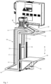
- figure 1 shows a preferred embodiment of a frame 1 of a welding device.
- the preferred frame 1 is used according to different preferred embodiments of the present invention in combination with a laser welder, or an infrared welder, or a vibration welder, or an ultrasonic welder, or a friction welder.
- the preferred embodiment of the frame 1 in figure 1 is shown without the welding device in order to be able to better illustrate the structural properties of the frame 1.
- the preferred frame 1 comprises a double frame 10 which has two vertical columns 12 arranged parallel to one another and next to one another.
- the vertical columns 12 are fixed at a lateral distance from one another on a base 18, here a plate.
- the base 18 ensures a stable and true-to-position arrangement of the vertical columns 12. While the lower end of the vertical columns 12, here the first end 14, is anchored in the base 18, adjacent to a second end 16 of the vertical columns 12, here the upper end of the Vertical columns 12, one cantilever arm 20, 22 is arranged on each vertical column 12.
- the cantilever arms 20, 22 are preferably formed integrally with the vertical columns 12 or are firmly connected to them.
- parallel guides 24 , 26 are provided on the vertical columns 12 . They are used to guide a movable table 30 or another component of the frame 1 or the welding device. Since the guides 24, 26 are attached to the vertical columns 12 and run parallel to the vertical columns, they serve to move a first table 30 in the direction of the fixed cantilever arms 20, 22.
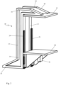
- figure 1 shows the double frame 10 as an S-shaped combination of cantilever 20, 22, vertical column 12 and base 18. It is also preferred to realize the double frame 10 C-shaped. To this end, the base 18 preferably extends to parallel and adjacent or opposed relationship to the cantilever arms 20, 22.
- a second table 32 is fixed to the cantilever arms 20,22.
- the tables 30, 32 illustrate the possibility of arranging tools or machining components of the welding devices mentioned above. Such tools and processing components and their arrangement and use are generally known in the prior art.
- An oscillating structure with a sonotrode is preferably attached to the table 32 in an ultrasonic welding device.
- the movable table 30 with the counter tool and the material can be moved in the direction of the cantilever arms 20, 22 and the first table 32 in order to produce a welded connection between the lengths of material.
- the sonotrode (not shown) hits the material webs of the table 32 or the roller and welds them together.
- an oscillating head is preferably provided on the table 32 instead of the sonotrode.
- a laser source or a laser source is preferably on the table 32 instead of the sonotrode Infrared source provided.
- the table 30 supports the counter tool in this infrared welding device or the laser welding device, respectively.
- the table 32 with a friction weld drive to effect a friction weld connection.
- the movable table 30 forms the anvil or the counter-tool on which a component to be connected is arranged.
- the table 30 moves in the direction of the arrow 1.
- the table 32 is firmly attached to the cantilever arm 20,22.
- the table 32 is movably arranged while the table 30 is fixedly positioned.
- the table 32 is preferably guided parallel to the vertical columns 12 and on the vertical columns 12 via rails (not shown).
- both tables 30, 32 are movably arranged on the vertical columns 12.
- guides 24, 26 are provided for both tables 30, 32 so that they can be displaced parallel to the vertical columns 12.
- the vertical columns 12 in combination with the base 18 and cantilevers 20, 22 implement a constant orientation of the tables 30, 32 with respect to one another.
- the construction of the double frame 10 ensures that the vertical columns 12 are not bent up and thus the orientation of the tables 30, 32 relative to one another is disturbed.
- a C-shaped drive unit 40 is provided for the preferred movement of one table 30 or both tables 30, 32 parallel to the vertical columns 12 (see FIG figure 1 and Figures 4-6 ).
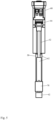
- the drive unit 40 comprises a first 42 and a second flange 44 which are connected to one another via a vertical leg 50 .
- the first 42 and the second flange 44 are arranged transversely to the vertical leg 50 and parallel to one another.
- am Vertical leg 50 guides 52 are provided so that at least the first flange 42 is movable in the manner of a carriage relative to the second leg 44 and parallel to the vertical leg 50 .
- both flanges 42, 44 are preferably mounted as carriages, respectively, to move them relative to one another.
- the drive unit 40 has a linear drive 60, 62.
- the linear drive 60, 62 can include all common linear drives. This preferably includes a spindle drive in which one flange 42 is connected to the spindle and the other flange 44 is connected to the nut. In another preferred embodiment of the linear drive 60, 62, this is implemented as a hydraulic or pneumatic piston-cylinder drive. In addition, an electromagnetic drive can also be used as a linear drive 60, 62.
- the drive unit 40 is arranged between and parallel to the vertical columns 12 of the double frame 10 .
- the first flange 42 is positioned adjacent to the table 30 .
- the second flange 44 is positioned adjacent to the table 32 .
- the respective flange 42, 44 and the table 30, 32 adjacent thereto are non-rigidly connected to one another.
- a preferred construction for making this non-rigid connection is ball joints between flange 42, 44 and table 30, 32.
- the linear drive 60, 62 shortens in the infeed direction 1, the flanges 42, 44 are moved relative to one another. Accordingly, the movable table 30 is displaced toward the fixed table 32 to perform a welding operation.
- the table 30 is displaced in the direction of the cantilever arms 20, 22.
- the double frame 10 and the drive unit 40 are mechanically combined with one another in such a way that they are decoupled in terms of bending.
- the guidance of the tables 30, 32 and the stability of the double frame 10 with the vertical columns 12 ensure that the bending moment of the drive unit 40 cannot be transferred to the double frame 10.
- the double frame 10 and the drive unit 40 are arranged so that they are decoupled from one another in terms of bending.
- the two flanges 42, 44 are non-rigidly connected to the tables 30, 32, preferably via a ball and socket joint. In the same way, it is preferred to arrange only one of the tables 30, 32 or both tables 30, 32 to be movable along the vertical columns 12. In order to apply a sufficient welding force to the components and tools based on this design, it is sufficient if the force generated by the linear drive 60, 62 is not introduced centrally into the tables 30, 32 via the flanges 42, 44. Because of the construction of the frame 1, the parallel orientation of the plates 30, 32 to one another is maintained despite non-decentralized introduction of force. This means that there is no transfer of a possible flexing of the drive unit 40 to the double frame 10 .
- the moving table 30 in the double frame 10 is equipped with a known force measuring sensor 70 .
- the data from the force measuring sensor 70 is forwarded to an industrial computer (not shown) as a control unit. This also controls or regulates welding processes that are implemented using the frame 1 .
- the welding method of the present invention is described using a preferred embodiment as an example for the other known welding devices mentioned above.
- an oscillating structure with a sonotrode is attached to the fixed table 32 .
- the table 30 moves a counter-tool, for example an anvil or a roller, in the direction of the sonotrode in order to weld material between the sonotrode and the counter-tool to one another.
- a web of material or a first component is arranged on the first table 30 .
- the first component is then moved relative to a tool, here the sonotrode. It is equally preferred that the first component is moved against a further component in order to connect them to one another by means of ultrasound or another energy supply.
- both tables 30, 32 are moved. This can easily be implemented with the drive unit 40 described above.
- step C a mechanical load is applied to the component to be welded by further shortening the drive unit 40 . Since the component or the components are pressed against one another between the sonotrode and the counter-tool in combination with the tables 32 and 30, ultrasonic vibrations are impressed into the materials/components to be connected to one another.
- step D the mechanical stress during the welding is recorded with the aid of the force measuring sensor 70 mentioned above.
- alternative measurement options such as strain gauges or the like, instead of the force measurement sensor 70 .
- the drive unit 40 controls a removal of the sonotrode and the component or counter-tool from one another.
- the two tables 30, 32 also move away from one another accordingly.
- the welded component or workpiece is removed from the welding device.
Landscapes
- Engineering & Computer Science (AREA)
- Mechanical Engineering (AREA)
- Lining Or Joining Of Plastics Or The Like (AREA)
- Pressure Welding/Diffusion-Bonding (AREA)
Claims (13)
- Support (1) pour un dispositif de soudage, en particulier un dispositif de soudage au laser ou un dispositif de soudage infrarouge ou un dispositif de soudage par vibration ou un dispositif de soudage à ultrasons, présentant les caractéristiques suivantes :a. un double cadre (10), lequel présente au moins deux colonnes verticales (12) fixées à une plaque de base (18) et disposées côte à côte et parallèlement les unes aux autres, et respectivement un bras en porte-à-faux (20, 22) fixé aux colonnes verticales (12),b. au moins une table (30) déplaçable parallèlement aux colonnes verticales (12), laquelle est guidée parallèlement sur les deux colonnes verticales (12),c. une unité d'entraînement en forme de C (40) comportant une première (42) et une deuxième bride (44), lesquelles sont guidées sur une branche verticale de liaison (50) de façon à pouvoir se déplacer linéairement l'une par rapport à l'autre, l'unité d'entraînement (40) permettant de modifier une distance entre la première (42) et le deuxième bride (44) en direction de la branche verticale (50), dans lequeld. l'unité d'entraînement en forme de C (40) est disposée entre les colonnes verticales (12) du double cadre (10) ete. la table (30) est déplaçable par rapport à une butée fixe (32) ou à une autre table déplaçable du double cadre (10) par le biais d'une liaison entre la première bride (42) et la table (30) du double cadre (10), la butée (32) ou la deuxième table étant reliée à la deuxième bride (44).
- Support (1) selon la revendication 1, dans lequel la liaison entre la première bride (42) et la table (30) est mobile.
- Support (1) selon la revendication 2, dans lequel la liaison entre la deuxième bride (44) et l'autre table (32) ou la butée est mobile.
- Support (1) selon l'une des revendications précédentes, dans lequel l'unité d'entraînement en forme de C (40) permet de déplacer l'au moins une table (30) du double cadre (10) vers l'autre table (32) ou vers la butée de manière désaccouplée en fléchissement, de façon à limiter un fléchissement du support (1) du fait de charges mécaniques orientées parallèlement aux colonnes verticales (12) sur l'unité d'entraînement en forme de C (40).
- Support (1) selon l'une des revendications précédentes, dans lequel les bras en porte-à-faux (20, 22) portent une deuxième table (32) disposée fixement, de préférence un logement d'outil, par rapport à laquelle/auquel la première table (30) est déplaçable.
- Support (1) selon la revendication 5, dans lequel la première bride (42) est reliée à la première table (30) par le biais d'un joint à rotule et la deuxième bride (44) est reliée à la deuxième table (32) par le biais d'un joint à rotule, dans lequel la première (42) et la deuxième bride (44) sont de préférence disposées perpendiculairement à la branche verticale (50).
- Support (1) selon l'une des revendications précédentes, dans lequel un capteur de mesure de force est disposé sur l'au moins une table déplaçable (30) du double cadre (10).
- Support (1) selon l'une des revendications précédentes, dans lequel la première (42) et la deuxième bride (44) de l'unité d'entraînement en forme de C (40) consistent en un premier et un deuxième chariot, lesquels sont montés sur un guide (52) le long de la branche verticale (50) et guidées de manière à pouvoir se déplacer linéairement.
- Dispositif de soudage en combinaison avec le support (1) selon l'une des revendications 1 à 8, comportant :un dispositif de soudage au laser ouun dispositif de soudage infrarouge ouun dispositif de soudage par vibration ouun dispositif de soudage par ultrasons.
- Utilisation du support (1) selon l'une des revendications précédentes 1 à 8, pour un soudage au laser, un soudage infrarouge, un soudage par vibration ou un soudage par ultrasons.
- Procédé de soudage avec un dispositif de soudage selon la revendication indépendante 9, présentant les étapes suivantes :a. agencement (étape A) d'au moins une première pièce sur la première table (30),b. déplacement relatif (B) de la première pièce vers un outil ou vers une deuxième pièce, lequel/laquelle est relié(e) à une butée ou à une autre table déplaçable (32), dans lequel la première bride (42) et la deuxième bride (44) de l'unité d'entraînement en forme de C (40) sont déplacées l'une vers l'autre,c. pendant le soudage, application (C) d'une charge mécanique sur la première pièce par l'unité d'entraînement en forme de C (40).
- Procédé de soudage selon la revendication 11, comprenant l'étape supplémentaire suivante :
détection (D) de charges mécaniques sur la pièce à l'aide d'au moins un capteur de mesure de force en combinaison avec la première table (30) ou à l'aide de jauges de contrainte sur l'unité d'entraînement en forme de C (40). - Procédé de soudage selon la revendication 11 ou 12, comprenant l'étape supplémentaire suivante :
introduction d'une charge mécanique de l'unité d'entraînement en forme de C (40) par le biais de liaisons non fixes dans la première table (30) et/ou la butée ou la deuxième table (32), de telle façon que le soudage n'est pas affecté malgré un fléchissement de l'unité d'entraînement en forme de C (40).
Applications Claiming Priority (2)
| Application Number | Priority Date | Filing Date | Title |
|---|---|---|---|
| DE102018119618.0A DE102018119618A1 (de) | 2018-08-13 | 2018-08-13 | Schweißvorrichtung und Gestell dafür |
| PCT/EP2019/070796 WO2020035326A1 (fr) | 2018-08-13 | 2019-08-01 | Dispositif de soudage et support pour celui-ci |
Publications (2)
| Publication Number | Publication Date |
|---|---|
| EP3820679A1 EP3820679A1 (fr) | 2021-05-19 |
| EP3820679B1 true EP3820679B1 (fr) | 2023-07-12 |
Family
ID=67544241
Family Applications (1)
| Application Number | Title | Priority Date | Filing Date |
|---|---|---|---|
| EP19749704.3A Active EP3820679B1 (fr) | 2018-08-13 | 2019-08-01 | Dispositif de soudage et support pour celui-ci |
Country Status (4)
| Country | Link |
|---|---|
| EP (1) | EP3820679B1 (fr) |
| DE (1) | DE102018119618A1 (fr) |
| ES (1) | ES2958119T3 (fr) |
| WO (1) | WO2020035326A1 (fr) |
Families Citing this family (2)
| Publication number | Priority date | Publication date | Assignee | Title |
|---|---|---|---|---|
| CN111673488A (zh) * | 2020-06-13 | 2020-09-18 | 浙江力扬威亚智能装备有限公司 | 一种数控机床用交换工作台 |
| CN115972589A (zh) * | 2022-12-19 | 2023-04-18 | 江苏大学 | 一种双向可精确调整的超声辅助激光连接装置 |
Family Cites Families (8)
| Publication number | Priority date | Publication date | Assignee | Title |
|---|---|---|---|---|
| DE2635348C3 (de) * | 1976-08-03 | 1981-04-09 | General Battery Corp., Reading, Pa. | Maschine zum Stumpfschweißen von Formteilen aus thermoplastischem Werkstoff |
| CS201349B1 (en) * | 1978-10-09 | 1980-10-31 | Vaclav Smrha | Facility for decreasing the deformation of the stands and frames of machines |
| US4584037A (en) | 1982-09-07 | 1986-04-22 | Cosden Technology, Inc. | Inertial spin welding of thermoplastic and thermoplastic coated container parts |
| EP0113389A1 (fr) * | 1982-12-10 | 1984-07-18 | MDC Max Dätwyler Bleienbach AG | Dispositif pour soulager la glissière de guidage pour organes mobiles principalement dans la direction verticale, en particulier organes de machines d'usinage |
| US5772103A (en) | 1996-09-25 | 1998-06-30 | Hofius, Sr.; David V. | Method and apparatus for friction torque welding |
| US5833127A (en) | 1996-12-12 | 1998-11-10 | Powell Mcgee Associates, Inc. | Method and apparatus for precision spin-welding |
| DE102014101627A1 (de) * | 2014-02-10 | 2015-08-13 | Ms Spaichingen Gmbh | Gestell für eine Maschine |
| DE102016102164A1 (de) * | 2016-02-08 | 2017-08-10 | Ms Ultraschall Technologie Gmbh | Ultraschall-Bearbeitungsmaschine |
-
2018
- 2018-08-13 DE DE102018119618.0A patent/DE102018119618A1/de not_active Withdrawn
-
2019
- 2019-08-01 WO PCT/EP2019/070796 patent/WO2020035326A1/fr not_active Ceased
- 2019-08-01 ES ES19749704T patent/ES2958119T3/es active Active
- 2019-08-01 EP EP19749704.3A patent/EP3820679B1/fr active Active
Also Published As
| Publication number | Publication date |
|---|---|
| WO2020035326A1 (fr) | 2020-02-20 |
| ES2958119T3 (es) | 2024-02-01 |
| DE102018119618A1 (de) | 2020-02-13 |
| EP3820679A1 (fr) | 2021-05-19 |
Similar Documents
| Publication | Publication Date | Title |
|---|---|---|
| EP2424724B2 (fr) | Scelleuse à ultrasons et procédé de scellage de bandes de matériau | |
| EP2905108B1 (fr) | Châssis d'une machine | |
| DE4495551C2 (de) | Z-Achsen-Antrieb für eine Werkzeugmaschine | |
| EP2416940B1 (fr) | Dispositif pour traiter un matériau d'emballage par ultrasons | |
| EP2783791B1 (fr) | Dispositif de positionnement avec portique | |
| EP3154722B1 (fr) | Presse à cintrer munie d'une unité de cintrage et procédé de formage | |
| AT523568B1 (de) | Biegemaschine | |
| DE69321827T2 (de) | Kombiniertes schneid- und schweissverfahren zur herstellung struktureller produkte, gerät zur durchführung eines solchen verfahrens und mittels dieses verfahrens hergestellter produkte | |
| DE2209845A1 (de) | Meßgerät, insbesondere Lagerung für Meßfühler | |
| EP3820679B1 (fr) | Dispositif de soudage et support pour celui-ci | |
| EP1607165A1 (fr) | Dispositif de soudage par friction agitation pour assembler des pièces avec un outil ayant deux épaulements pouvant tourner dans une direction opposée | |
| EP2846966B1 (fr) | Centre de transfert destiné à usiner au moins une pièce par enlèvement de matière, comprenant un système de compensation de position | |
| EP3112083B1 (fr) | Système de portique d'une machine-outil et machine-outil avec un tel système de portique | |
| EP3160726B1 (fr) | Presse à châssis en c, améliorée | |
| EP2495069B1 (fr) | Machine-outil dotée d'une table de pièce usinée | |
| EP3231585A1 (fr) | Dispositif de soudage par ultrasons | |
| EP2887513B1 (fr) | Système de moteur linéaire et machine-outil dotée d'un système de moteur linéaire | |
| EP3481565B1 (fr) | Machine de formage par étirage et procédé de mise en forme d'une pièce | |
| EP3552729A1 (fr) | Dispositif d'installation de rivets auto-poinçonneurs | |
| EP0499019B1 (fr) | Machine de soudage par résistance, particulièrement pour le soudage par résistance par fusion | |
| EP1941956A1 (fr) | Presse de pliage destinée à plier une tôle lors de la fabrication d'un tuyau | |
| EP1849591B1 (fr) | Presse | |
| EP0439665B1 (fr) | Machine à souder pour largets | |
| DE3607875C2 (fr) | ||
| DE102011005632B4 (de) | Aufbaustand zum Zusammenfügen von Wagenkasten-Baugruppen |
Legal Events
| Date | Code | Title | Description |
|---|---|---|---|
| STAA | Information on the status of an ep patent application or granted ep patent |
Free format text: STATUS: UNKNOWN |
|
| STAA | Information on the status of an ep patent application or granted ep patent |
Free format text: STATUS: THE INTERNATIONAL PUBLICATION HAS BEEN MADE |
|
| PUAI | Public reference made under article 153(3) epc to a published international application that has entered the european phase |
Free format text: ORIGINAL CODE: 0009012 |
|
| STAA | Information on the status of an ep patent application or granted ep patent |
Free format text: STATUS: REQUEST FOR EXAMINATION WAS MADE |
|
| 17P | Request for examination filed |
Effective date: 20210215 |
|
| AK | Designated contracting states |
Kind code of ref document: A1 Designated state(s): AL AT BE BG CH CY CZ DE DK EE ES FI FR GB GR HR HU IE IS IT LI LT LU LV MC MK MT NL NO PL PT RO RS SE SI SK SM TR |
|
| DAV | Request for validation of the european patent (deleted) | ||
| DAX | Request for extension of the european patent (deleted) | ||
| GRAP | Despatch of communication of intention to grant a patent |
Free format text: ORIGINAL CODE: EPIDOSNIGR1 |
|
| STAA | Information on the status of an ep patent application or granted ep patent |
Free format text: STATUS: GRANT OF PATENT IS INTENDED |
|
| INTG | Intention to grant announced |
Effective date: 20230301 |
|
| GRAS | Grant fee paid |
Free format text: ORIGINAL CODE: EPIDOSNIGR3 |
|
| GRAA | (expected) grant |
Free format text: ORIGINAL CODE: 0009210 |
|
| STAA | Information on the status of an ep patent application or granted ep patent |
Free format text: STATUS: THE PATENT HAS BEEN GRANTED |
|
| AK | Designated contracting states |
Kind code of ref document: B1 Designated state(s): AL AT BE BG CH CY CZ DE DK EE ES FI FR GB GR HR HU IE IS IT LI LT LU LV MC MK MT NL NO PL PT RO RS SE SI SK SM TR |
|
| P01 | Opt-out of the competence of the unified patent court (upc) registered |
Effective date: 20230601 |
|
| REG | Reference to a national code |
Ref country code: CH Ref legal event code: EP |
|
| REG | Reference to a national code |
Ref country code: DE Ref legal event code: R096 Ref document number: 502019008518 Country of ref document: DE |
|
| REG | Reference to a national code |
Ref country code: IE Ref legal event code: FG4D Free format text: LANGUAGE OF EP DOCUMENT: GERMAN |
|
| PGFP | Annual fee paid to national office [announced via postgrant information from national office to epo] |
Ref country code: GB Payment date: 20230822 Year of fee payment: 5 Ref country code: ES Payment date: 20230918 Year of fee payment: 5 Ref country code: CH Payment date: 20230902 Year of fee payment: 5 |
|
| REG | Reference to a national code |
Ref country code: LT Ref legal event code: MG9D |
|
| REG | Reference to a national code |
Ref country code: NL Ref legal event code: MP Effective date: 20230712 |
|
| PGFP | Annual fee paid to national office [announced via postgrant information from national office to epo] |
Ref country code: FR Payment date: 20230823 Year of fee payment: 5 |
|
| PG25 | Lapsed in a contracting state [announced via postgrant information from national office to epo] |
Ref country code: NL Free format text: LAPSE BECAUSE OF FAILURE TO SUBMIT A TRANSLATION OF THE DESCRIPTION OR TO PAY THE FEE WITHIN THE PRESCRIBED TIME-LIMIT Effective date: 20230712 |
|
| PG25 | Lapsed in a contracting state [announced via postgrant information from national office to epo] |
Ref country code: GR Free format text: LAPSE BECAUSE OF FAILURE TO SUBMIT A TRANSLATION OF THE DESCRIPTION OR TO PAY THE FEE WITHIN THE PRESCRIBED TIME-LIMIT Effective date: 20231013 |
|
| PG25 | Lapsed in a contracting state [announced via postgrant information from national office to epo] |
Ref country code: IS Free format text: LAPSE BECAUSE OF FAILURE TO SUBMIT A TRANSLATION OF THE DESCRIPTION OR TO PAY THE FEE WITHIN THE PRESCRIBED TIME-LIMIT Effective date: 20231112 |
|
| PG25 | Lapsed in a contracting state [announced via postgrant information from national office to epo] |
Ref country code: SE Free format text: LAPSE BECAUSE OF FAILURE TO SUBMIT A TRANSLATION OF THE DESCRIPTION OR TO PAY THE FEE WITHIN THE PRESCRIBED TIME-LIMIT Effective date: 20230712 Ref country code: RS Free format text: LAPSE BECAUSE OF FAILURE TO SUBMIT A TRANSLATION OF THE DESCRIPTION OR TO PAY THE FEE WITHIN THE PRESCRIBED TIME-LIMIT Effective date: 20230712 Ref country code: PT Free format text: LAPSE BECAUSE OF FAILURE TO SUBMIT A TRANSLATION OF THE DESCRIPTION OR TO PAY THE FEE WITHIN THE PRESCRIBED TIME-LIMIT Effective date: 20231113 Ref country code: NO Free format text: LAPSE BECAUSE OF FAILURE TO SUBMIT A TRANSLATION OF THE DESCRIPTION OR TO PAY THE FEE WITHIN THE PRESCRIBED TIME-LIMIT Effective date: 20231012 Ref country code: LV Free format text: LAPSE BECAUSE OF FAILURE TO SUBMIT A TRANSLATION OF THE DESCRIPTION OR TO PAY THE FEE WITHIN THE PRESCRIBED TIME-LIMIT Effective date: 20230712 Ref country code: LT Free format text: LAPSE BECAUSE OF FAILURE TO SUBMIT A TRANSLATION OF THE DESCRIPTION OR TO PAY THE FEE WITHIN THE PRESCRIBED TIME-LIMIT Effective date: 20230712 Ref country code: IS Free format text: LAPSE BECAUSE OF FAILURE TO SUBMIT A TRANSLATION OF THE DESCRIPTION OR TO PAY THE FEE WITHIN THE PRESCRIBED TIME-LIMIT Effective date: 20231112 Ref country code: HR Free format text: LAPSE BECAUSE OF FAILURE TO SUBMIT A TRANSLATION OF THE DESCRIPTION OR TO PAY THE FEE WITHIN THE PRESCRIBED TIME-LIMIT Effective date: 20230712 Ref country code: GR Free format text: LAPSE BECAUSE OF FAILURE TO SUBMIT A TRANSLATION OF THE DESCRIPTION OR TO PAY THE FEE WITHIN THE PRESCRIBED TIME-LIMIT Effective date: 20231013 Ref country code: FI Free format text: LAPSE BECAUSE OF FAILURE TO SUBMIT A TRANSLATION OF THE DESCRIPTION OR TO PAY THE FEE WITHIN THE PRESCRIBED TIME-LIMIT Effective date: 20230712 |
|
| PGFP | Annual fee paid to national office [announced via postgrant information from national office to epo] |
Ref country code: IT Payment date: 20231103 Year of fee payment: 5 Ref country code: DE Payment date: 20231025 Year of fee payment: 5 |
|
| REG | Reference to a national code |
Ref country code: ES Ref legal event code: FG2A Ref document number: 2958119 Country of ref document: ES Kind code of ref document: T3 Effective date: 20240201 |
|
| PG25 | Lapsed in a contracting state [announced via postgrant information from national office to epo] |
Ref country code: PL Free format text: LAPSE BECAUSE OF FAILURE TO SUBMIT A TRANSLATION OF THE DESCRIPTION OR TO PAY THE FEE WITHIN THE PRESCRIBED TIME-LIMIT Effective date: 20230712 |
|
| REG | Reference to a national code |
Ref country code: DE Ref legal event code: R097 Ref document number: 502019008518 Country of ref document: DE |
|
| PG25 | Lapsed in a contracting state [announced via postgrant information from national office to epo] |
Ref country code: LU Free format text: LAPSE BECAUSE OF NON-PAYMENT OF DUE FEES Effective date: 20230801 |
|
| PG25 | Lapsed in a contracting state [announced via postgrant information from national office to epo] |
Ref country code: SM Free format text: LAPSE BECAUSE OF FAILURE TO SUBMIT A TRANSLATION OF THE DESCRIPTION OR TO PAY THE FEE WITHIN THE PRESCRIBED TIME-LIMIT Effective date: 20230712 Ref country code: RO Free format text: LAPSE BECAUSE OF FAILURE TO SUBMIT A TRANSLATION OF THE DESCRIPTION OR TO PAY THE FEE WITHIN THE PRESCRIBED TIME-LIMIT Effective date: 20230712 Ref country code: LU Free format text: LAPSE BECAUSE OF NON-PAYMENT OF DUE FEES Effective date: 20230801 Ref country code: EE Free format text: LAPSE BECAUSE OF FAILURE TO SUBMIT A TRANSLATION OF THE DESCRIPTION OR TO PAY THE FEE WITHIN THE PRESCRIBED TIME-LIMIT Effective date: 20230712 Ref country code: DK Free format text: LAPSE BECAUSE OF FAILURE TO SUBMIT A TRANSLATION OF THE DESCRIPTION OR TO PAY THE FEE WITHIN THE PRESCRIBED TIME-LIMIT Effective date: 20230712 Ref country code: CZ Free format text: LAPSE BECAUSE OF FAILURE TO SUBMIT A TRANSLATION OF THE DESCRIPTION OR TO PAY THE FEE WITHIN THE PRESCRIBED TIME-LIMIT Effective date: 20230712 Ref country code: MC Free format text: LAPSE BECAUSE OF FAILURE TO SUBMIT A TRANSLATION OF THE DESCRIPTION OR TO PAY THE FEE WITHIN THE PRESCRIBED TIME-LIMIT Effective date: 20230712 Ref country code: SK Free format text: LAPSE BECAUSE OF FAILURE TO SUBMIT A TRANSLATION OF THE DESCRIPTION OR TO PAY THE FEE WITHIN THE PRESCRIBED TIME-LIMIT Effective date: 20230712 |
|
| REG | Reference to a national code |
Ref country code: BE Ref legal event code: MM Effective date: 20230831 |
|
| PLBE | No opposition filed within time limit |
Free format text: ORIGINAL CODE: 0009261 |
|
| STAA | Information on the status of an ep patent application or granted ep patent |
Free format text: STATUS: NO OPPOSITION FILED WITHIN TIME LIMIT |
|
| REG | Reference to a national code |
Ref country code: IE Ref legal event code: MM4A |
|
| 26N | No opposition filed |
Effective date: 20240415 |
|
| PG25 | Lapsed in a contracting state [announced via postgrant information from national office to epo] |
Ref country code: IE Free format text: LAPSE BECAUSE OF NON-PAYMENT OF DUE FEES Effective date: 20230801 |
|
| PG25 | Lapsed in a contracting state [announced via postgrant information from national office to epo] |
Ref country code: IE Free format text: LAPSE BECAUSE OF NON-PAYMENT OF DUE FEES Effective date: 20230801 Ref country code: SI Free format text: LAPSE BECAUSE OF FAILURE TO SUBMIT A TRANSLATION OF THE DESCRIPTION OR TO PAY THE FEE WITHIN THE PRESCRIBED TIME-LIMIT Effective date: 20230712 |
|
| PG25 | Lapsed in a contracting state [announced via postgrant information from national office to epo] |
Ref country code: BE Free format text: LAPSE BECAUSE OF NON-PAYMENT OF DUE FEES Effective date: 20230831 |
|
| PG25 | Lapsed in a contracting state [announced via postgrant information from national office to epo] |
Ref country code: BG Free format text: LAPSE BECAUSE OF FAILURE TO SUBMIT A TRANSLATION OF THE DESCRIPTION OR TO PAY THE FEE WITHIN THE PRESCRIBED TIME-LIMIT Effective date: 20230712 |
|
| PG25 | Lapsed in a contracting state [announced via postgrant information from national office to epo] |
Ref country code: BG Free format text: LAPSE BECAUSE OF FAILURE TO SUBMIT A TRANSLATION OF THE DESCRIPTION OR TO PAY THE FEE WITHIN THE PRESCRIBED TIME-LIMIT Effective date: 20230712 |
|
| REG | Reference to a national code |
Ref country code: DE Ref legal event code: R119 Ref document number: 502019008518 Country of ref document: DE |
|
| REG | Reference to a national code |
Ref country code: CH Ref legal event code: PL |
|
| GBPC | Gb: european patent ceased through non-payment of renewal fee |
Effective date: 20240801 |
|
| PG25 | Lapsed in a contracting state [announced via postgrant information from national office to epo] |
Ref country code: CH Free format text: LAPSE BECAUSE OF NON-PAYMENT OF DUE FEES Effective date: 20240831 |
|
| PG25 | Lapsed in a contracting state [announced via postgrant information from national office to epo] |
Ref country code: DE Free format text: LAPSE BECAUSE OF NON-PAYMENT OF DUE FEES Effective date: 20250301 |
|
| PG25 | Lapsed in a contracting state [announced via postgrant information from national office to epo] |
Ref country code: GB Free format text: LAPSE BECAUSE OF NON-PAYMENT OF DUE FEES Effective date: 20240801 |
|
| PG25 | Lapsed in a contracting state [announced via postgrant information from national office to epo] |
Ref country code: IT Free format text: LAPSE BECAUSE OF NON-PAYMENT OF DUE FEES Effective date: 20240801 |
|
| PG25 | Lapsed in a contracting state [announced via postgrant information from national office to epo] |
Ref country code: FR Free format text: LAPSE BECAUSE OF NON-PAYMENT OF DUE FEES Effective date: 20240831 |
|
| PG25 | Lapsed in a contracting state [announced via postgrant information from national office to epo] |
Ref country code: CY Free format text: LAPSE BECAUSE OF FAILURE TO SUBMIT A TRANSLATION OF THE DESCRIPTION OR TO PAY THE FEE WITHIN THE PRESCRIBED TIME-LIMIT; INVALID AB INITIO Effective date: 20190801 |
|
| PG25 | Lapsed in a contracting state [announced via postgrant information from national office to epo] |
Ref country code: HU Free format text: LAPSE BECAUSE OF FAILURE TO SUBMIT A TRANSLATION OF THE DESCRIPTION OR TO PAY THE FEE WITHIN THE PRESCRIBED TIME-LIMIT; INVALID AB INITIO Effective date: 20190801 |
|
| REG | Reference to a national code |
Ref country code: ES Ref legal event code: FD2A Effective date: 20250926 |
|
| PG25 | Lapsed in a contracting state [announced via postgrant information from national office to epo] |
Ref country code: ES Free format text: LAPSE BECAUSE OF NON-PAYMENT OF DUE FEES Effective date: 20240802 |
|
| REG | Reference to a national code |
Ref country code: AT Ref legal event code: MM01 Ref document number: 1586674 Country of ref document: AT Kind code of ref document: T Effective date: 20240801 |
|
| PG25 | Lapsed in a contracting state [announced via postgrant information from national office to epo] |
Ref country code: AT Free format text: LAPSE BECAUSE OF NON-PAYMENT OF DUE FEES Effective date: 20240801 |
|
| PG25 | Lapsed in a contracting state [announced via postgrant information from national office to epo] |
Ref country code: TR Free format text: LAPSE BECAUSE OF FAILURE TO SUBMIT A TRANSLATION OF THE DESCRIPTION OR TO PAY THE FEE WITHIN THE PRESCRIBED TIME-LIMIT Effective date: 20230712 |
|
| PGFP | Annual fee paid to national office [announced via postgrant information from national office to epo] |
Ref country code: AT Payment date: 20260410 Year of fee payment: 5 |