EP3820679B1 - Schweissvorrichtung und gestell dafür - Google Patents
Schweissvorrichtung und gestell dafür Download PDFInfo
- Publication number
- EP3820679B1 EP3820679B1 EP19749704.3A EP19749704A EP3820679B1 EP 3820679 B1 EP3820679 B1 EP 3820679B1 EP 19749704 A EP19749704 A EP 19749704A EP 3820679 B1 EP3820679 B1 EP 3820679B1
- Authority
- EP
- European Patent Office
- Prior art keywords
- drive unit
- welding
- flange
- welding device
- rack
- Prior art date
- Legal status (The legal status is an assumption and is not a legal conclusion. Google has not performed a legal analysis and makes no representation as to the accuracy of the status listed.)
- Active
Links
Images




Classifications
-
- B—PERFORMING OPERATIONS; TRANSPORTING
- B29—WORKING OF PLASTICS; WORKING OF SUBSTANCES IN A PLASTIC STATE IN GENERAL
- B29C—SHAPING OR JOINING OF PLASTICS; SHAPING OF MATERIAL IN A PLASTIC STATE, NOT OTHERWISE PROVIDED FOR; AFTER-TREATMENT OF THE SHAPED PRODUCTS, e.g. REPAIRING
- B29C66/00—General aspects of processes or apparatus for joining preformed parts
- B29C66/80—General aspects of machine operations or constructions and parts thereof
- B29C66/83—General aspects of machine operations or constructions and parts thereof characterised by the movement of the joining or pressing tools
- B29C66/832—Reciprocating joining or pressing tools
- B29C66/8322—Joining or pressing tools reciprocating along one axis
-
- B—PERFORMING OPERATIONS; TRANSPORTING
- B29—WORKING OF PLASTICS; WORKING OF SUBSTANCES IN A PLASTIC STATE IN GENERAL
- B29C—SHAPING OR JOINING OF PLASTICS; SHAPING OF MATERIAL IN A PLASTIC STATE, NOT OTHERWISE PROVIDED FOR; AFTER-TREATMENT OF THE SHAPED PRODUCTS, e.g. REPAIRING
- B29C65/00—Joining or sealing of preformed parts, e.g. welding of plastics materials; Apparatus therefor
- B29C65/02—Joining or sealing of preformed parts, e.g. welding of plastics materials; Apparatus therefor by heating, with or without pressure
-
- B—PERFORMING OPERATIONS; TRANSPORTING
- B29—WORKING OF PLASTICS; WORKING OF SUBSTANCES IN A PLASTIC STATE IN GENERAL
- B29C—SHAPING OR JOINING OF PLASTICS; SHAPING OF MATERIAL IN A PLASTIC STATE, NOT OTHERWISE PROVIDED FOR; AFTER-TREATMENT OF THE SHAPED PRODUCTS, e.g. REPAIRING
- B29C66/00—General aspects of processes or apparatus for joining preformed parts
- B29C66/80—General aspects of machine operations or constructions and parts thereof
- B29C66/84—Specific machine types or machines suitable for specific applications
- B29C66/845—C-clamp type or sewing machine type
-
- B—PERFORMING OPERATIONS; TRANSPORTING
- B29—WORKING OF PLASTICS; WORKING OF SUBSTANCES IN A PLASTIC STATE IN GENERAL
- B29C—SHAPING OR JOINING OF PLASTICS; SHAPING OF MATERIAL IN A PLASTIC STATE, NOT OTHERWISE PROVIDED FOR; AFTER-TREATMENT OF THE SHAPED PRODUCTS, e.g. REPAIRING
- B29C66/00—General aspects of processes or apparatus for joining preformed parts
- B29C66/90—Measuring or controlling the joining process
- B29C66/92—Measuring or controlling the joining process by measuring or controlling the pressure, the force, the mechanical power or the displacement of the joining tools
- B29C66/922—Measuring or controlling the joining process by measuring or controlling the pressure, the force, the mechanical power or the displacement of the joining tools by measuring the pressure, the force, the mechanical power or the displacement of the joining tools
- B29C66/9221—Measuring or controlling the joining process by measuring or controlling the pressure, the force, the mechanical power or the displacement of the joining tools by measuring the pressure, the force, the mechanical power or the displacement of the joining tools by measuring the pressure, the force or the mechanical power
- B29C66/92211—Measuring or controlling the joining process by measuring or controlling the pressure, the force, the mechanical power or the displacement of the joining tools by measuring the pressure, the force, the mechanical power or the displacement of the joining tools by measuring the pressure, the force or the mechanical power with special measurement means or methods
-
- B—PERFORMING OPERATIONS; TRANSPORTING
- B29—WORKING OF PLASTICS; WORKING OF SUBSTANCES IN A PLASTIC STATE IN GENERAL
- B29C—SHAPING OR JOINING OF PLASTICS; SHAPING OF MATERIAL IN A PLASTIC STATE, NOT OTHERWISE PROVIDED FOR; AFTER-TREATMENT OF THE SHAPED PRODUCTS, e.g. REPAIRING
- B29C65/00—Joining or sealing of preformed parts, e.g. welding of plastics materials; Apparatus therefor
- B29C65/02—Joining or sealing of preformed parts, e.g. welding of plastics materials; Apparatus therefor by heating, with or without pressure
- B29C65/06—Joining or sealing of preformed parts, e.g. welding of plastics materials; Apparatus therefor by heating, with or without pressure using friction, e.g. spin welding
-
- B—PERFORMING OPERATIONS; TRANSPORTING
- B29—WORKING OF PLASTICS; WORKING OF SUBSTANCES IN A PLASTIC STATE IN GENERAL
- B29C—SHAPING OR JOINING OF PLASTICS; SHAPING OF MATERIAL IN A PLASTIC STATE, NOT OTHERWISE PROVIDED FOR; AFTER-TREATMENT OF THE SHAPED PRODUCTS, e.g. REPAIRING
- B29C65/00—Joining or sealing of preformed parts, e.g. welding of plastics materials; Apparatus therefor
- B29C65/02—Joining or sealing of preformed parts, e.g. welding of plastics materials; Apparatus therefor by heating, with or without pressure
- B29C65/08—Joining or sealing of preformed parts, e.g. welding of plastics materials; Apparatus therefor by heating, with or without pressure using ultrasonic vibrations
-
- B—PERFORMING OPERATIONS; TRANSPORTING
- B29—WORKING OF PLASTICS; WORKING OF SUBSTANCES IN A PLASTIC STATE IN GENERAL
- B29C—SHAPING OR JOINING OF PLASTICS; SHAPING OF MATERIAL IN A PLASTIC STATE, NOT OTHERWISE PROVIDED FOR; AFTER-TREATMENT OF THE SHAPED PRODUCTS, e.g. REPAIRING
- B29C65/00—Joining or sealing of preformed parts, e.g. welding of plastics materials; Apparatus therefor
- B29C65/02—Joining or sealing of preformed parts, e.g. welding of plastics materials; Apparatus therefor by heating, with or without pressure
- B29C65/14—Joining or sealing of preformed parts, e.g. welding of plastics materials; Apparatus therefor by heating, with or without pressure using wave energy, i.e. electromagnetic radiation, or particle radiation
- B29C65/1403—Joining or sealing of preformed parts, e.g. welding of plastics materials; Apparatus therefor by heating, with or without pressure using wave energy, i.e. electromagnetic radiation, or particle radiation characterised by the type of electromagnetic or particle radiation
- B29C65/1412—Infrared [IR] radiation
-
- B—PERFORMING OPERATIONS; TRANSPORTING
- B29—WORKING OF PLASTICS; WORKING OF SUBSTANCES IN A PLASTIC STATE IN GENERAL
- B29C—SHAPING OR JOINING OF PLASTICS; SHAPING OF MATERIAL IN A PLASTIC STATE, NOT OTHERWISE PROVIDED FOR; AFTER-TREATMENT OF THE SHAPED PRODUCTS, e.g. REPAIRING
- B29C65/00—Joining or sealing of preformed parts, e.g. welding of plastics materials; Apparatus therefor
- B29C65/02—Joining or sealing of preformed parts, e.g. welding of plastics materials; Apparatus therefor by heating, with or without pressure
- B29C65/14—Joining or sealing of preformed parts, e.g. welding of plastics materials; Apparatus therefor by heating, with or without pressure using wave energy, i.e. electromagnetic radiation, or particle radiation
- B29C65/16—Laser beams
-
- B—PERFORMING OPERATIONS; TRANSPORTING
- B29—WORKING OF PLASTICS; WORKING OF SUBSTANCES IN A PLASTIC STATE IN GENERAL
- B29C—SHAPING OR JOINING OF PLASTICS; SHAPING OF MATERIAL IN A PLASTIC STATE, NOT OTHERWISE PROVIDED FOR; AFTER-TREATMENT OF THE SHAPED PRODUCTS, e.g. REPAIRING
- B29C66/00—General aspects of processes or apparatus for joining preformed parts
- B29C66/80—General aspects of machine operations or constructions and parts thereof
- B29C66/81—General aspects of the pressing elements, i.e. the elements applying pressure on the parts to be joined in the area to be joined, e.g. the welding jaws or clamps
- B29C66/816—General aspects of the pressing elements, i.e. the elements applying pressure on the parts to be joined in the area to be joined, e.g. the welding jaws or clamps characterised by the mounting of the pressing elements, e.g. of the welding jaws or clamps
- B29C66/8163—Self-aligning to the joining plane, e.g. mounted on a ball and socket
Definitions
- the present invention relates to a welding device, in particular a laser welding device, an infrared welding device, a vibration welding device or an ultrasonic welding device, and a frame for realizing said welding device.
- the present invention relates to a welding method which can be implemented with the aid of the welding device arranged in the above-mentioned frame.
- the US Patents U.S. 4,584,037 , U.S. 5,772,103 and U.S. 5,833,127 comprise a vertical column on which a welding device is arranged so that it can be moved vertically via a cantilever arm.
- a welding device is arranged so that it can be moved vertically via a cantilever arm.
- the components are pressed against one another in a rotating manner in order to generate the necessary heat for welding the two components that are in contact with one another via the friction that occurs during rotation.
- a necessary pressure or a force applied by the frame to the two components to be connected to one another ensures that a reliable welded connection is formed.
- the pressure/force mentioned above also acts in the vertical direction in the same way as the orientation of the vertical stand.
- the vertical stand will bend up or deviate from its vertical orientation. This is the case in particular when the mechanical load on the components causes lateral forces that deform the vertical stand in a lateral direction against its rigidity. Accordingly, the vertical stand experiences a bending moment, so that the components to be connected are tilted out of their parallel arrangement. As a result, the weld joint formed between the two components is formed unevenly.
- the German utility model DE 83 16 643 describes a frame for machine tools or other processing devices.
- the frame of this device is characterized in that a spindle box is provided for movement in the z-direction, ie in the vertical direction, for machining a component.
- This headstock is held on two parallel vertical guide rails.
- a C-beam with a drive unit is also arranged between these guides. Since the headstock is not only suspended from the vertical guides, but also from the intermediate C-beam, the mechanical weight forces of the headstock are distributed over the vertical guides and the C-beam. Accordingly, the vertical guides are relieved of the transverse tensile loads on the spindle box, since part of its weight is absorbed by the central suspension device of the C-beam.
- EP 2 905 108 B1 Another frame for an ultrasonic welding device is disclosed EP 2 905 108 B1 .
- This frame uses a central C-beam on which two vertically movable cantilever arms are arranged in the form of carriages.
- a linear drive is provided on the upper cantilever arm or carriage, which represents an adjustment unit for the carriage arranged underneath.
- To relieve the central C-beam with drive there are C-shaped brackets on the side arranged. These C-shaped brackets absorb any bending of the C-beam with the drive. This is intended to ensure that the sonotrode and anvil are arranged in parallel.
- the mechanical relief provided by using the C-shaped brackets is often not sufficient. It is therefore additionally necessary to arrange the drive unit and the oscillating structure in alignment in the present frame. This aligned arrangement of the oscillating structure and drive unit prevents a possible bending moment on the carriage that carries the oscillating structure. In addition to the complex construction, it is precisely the absolutely necessary aligned arrangement of the drive unit and oscillating structure that ensures that a large installation space is available. This is because the drive unit is arranged above the oscillating structure and therefore protrudes beyond the oscillating structure and the frame of the welding device.
- a method for heat sealing with a machine having heating plates and a device for changing and aligning the heating plates are in DE 26 35 348 A1 described.
- the machine includes a heated platen on a movable carriage to advance into position between the parts to be joined.
- Spare plates are mounted in a fixed slide rail at right angles to the direction of movement of the carriage. In the retracted position of the carriage, part of the slide rail on the carriage aligns with the fixed rail, allowing the fresh plate to be easily positioned.
- the machine is used to connect covers to electrical battery cases. The plates can be exchanged quickly without waiting for the used plate to cool down.
- a frame for a welding device in particular a laser welding device or an infrared welding device or a vibration welding device or an ultrasonic welding device, according to independent patent claim 1 .
- the above object is achieved by a welding device in combination with the above frame according to independent patent claim 9 and the use of the frame for laser welding, infrared welding, vibration welding or ultrasonic welding according to independent patent claim 10.
- the above object is also achieved by the welding method according to independent patent claim 11.
- the frame according to the invention for a welding device has the following features on a double frame, which has at least two vertical columns fastened to a base plate and arranged parallel to one another and next to one another and one cantilever arm fastened to each of the vertical columns has, at least one table that can be moved parallel to the vertical columns and is guided parallel to the two vertical columns, a C-shaped drive unit that comprises a first and a second flange that are guided to be linearly movable relative to one another on a connecting vertical leg, in which with of the drive unit, a distance between the first and the second flange can be changed in the direction of the vertical leg, the C-shaped drive unit being arranged between the vertical columns of the double frame and the table being relatively fixed against a rigid one via a connection between the first flange and the table of the double frame Counter bearing or against a further movable table of the double frame is movable, wherein the
- the frame of the present invention features the mechanically decoupled combination and nesting of various load-bearing structures for joining devices with vertical load application.
- the said double frame is provided. This guides the components or tools or oscillating structures or the like towards one another in the vertical direction.
- the cantilever arms which project laterally away from the two vertical columns and are preferably arranged transversely to the vertical columns, form a mechanical support for the moving components, tools and the like.
- the construction of the double frame is characterized by the fact that it does not tend to deform during a welding process due to its stability and its mechanical decoupling from the load-generating drive unit. This ensures that during the welding process the two components to be connected or the arrangement of the oscillating structure and anvil or the arrangement of the tool and counter bearing in their Orientation to each other are held securely. This is because the drive unit is not rigidly connected to the components that move relative to one another, such as the table and counter bearing. Therefore, even if the power unit experiences a bending moment due to the load, the bending moment is not transmitted to the double frame.
- the C-shaped drive unit is arranged in between in the double frame.
- This C-shaped drive unit thus serves to apply the welding force via the displaceable table to the components and/or tools and/or oscillating structures or the like arranged between the displaceable table and the counter bearing.
- the double frame ensures the defined orientation of the moving table and/or the counter bearing and/or the tool and/or the oscillating structure and/or the components and/or another moving table, the C-shaped drive unit generates the necessary for welding Force in the vertical direction or parallel to the vertical columns.
- connection between the first flange and the table is designed to be movable.
- connection between the second flange and the further table or the counter bearing is designed to be movable. Movable in this context means that deformations and/or movements of the drive unit are not transferred to the double frame. It is therefore a connection that transmits mechanical loads.
- the C-shaped drive unit can be used to move the at least one table of the double frame in a manner decoupled from bending up against the other table or the counter bearing in such a way that the frame, in particular the double frame, bends up due to mechanical loads in the direction parallel to the vertical columns limited, preferably prevented, to the C-shaped drive unit.
- the cantilever arms carry a fixed second table, preferably a tool holder, against which the first table can be moved.
- the cantilevers are preferably fixed in the vertical direction adjacent to the upper end of the vertical columns.
- a table that preferably runs transversely to the vertical columns is supported on them in a fixed arrangement, so that a tool or a moving table can be moved against this fixed second table for a welding process.
- both the fixed table and the movable table are guided on the vertical columns of the double frame, these two tables, which are moved toward one another, are preferably aligned parallel to one another.
- the purposeful orientation of the tables that can be moved towards one another should ensure that they support an optimal arrangement and alignment of the components to be connected to one another.
- the orientation of the components to be connected to one another is guaranteed and is preferably constant despite the application of a welding force. Because any deflection that may be caused by the mechanical stress of the welding force is absorbed by the C-shaped drive unit alone, while the double frame maintains its shape.
- the first flange is connected to the second table via a ball joint and the second flange is connected to the first table via a ball joint, with the first and second flange preferably being arranged transversely to the vertical leg.
- the frame according to the invention described above it is ensured that a reliable welding force is introduced into the components to be connected, the tables or tools, despite a possible bending open of the C-shaped drive unit. It is essential that the orientation of the tables, which can be moved relative to one another, is not impaired by the possible attachment of the C-shaped drive unit.
- a ball and socket joint is provided for the connection between the first and second flanges of the C-shaped drive unit and the adjacently arranged table or tool or other components of the welding apparatus.
- a force measuring sensor is provided on the at least one movable table of the double frame.
- a device with a frame as an alternative to a force measuring sensor, with which a mechanical load during a welding process can also be reliably detected.
- the first and the second flange of the C-shaped drive unit have a first and a second slide, which are mounted on a guide along the vertical leg and are guided so as to be linearly movable.
- These carriages transmit the movement required for welding processes to the parts of the double frame which can be moved relative to one another.
- these carriages transmit the required welding force to the components or tools or oscillating structures and counter tools etc. arranged in the double frame.
- the carriages described here are also non-rigidly connected to the tables or similar arrangements of the double frame that can be moved relative to one another. Because only this non-rigid connection ensures that a possible bending of the C-shaped drive unit is not transferred to the weld connection to be made via the carriage.
- the present invention also includes a welding device in combination with the frame described above.
- This welding device uses a laser welding device, or an infrared welding device, or a vibration welding device, or an ultrasonic welding device, or a rotary friction welding device.
- the present invention includes the use of the frame according to one of the preferred embodiments described above for laser welding or infrared welding or vibration welding or ultrasonic welding or rotary friction welding.
- the present invention also includes a welding method for one of the welding devices described above.
- This welding process has the following steps: Arrange at least one first component on the first table, relatively moving the first component against a tool or a second component connected to an anvil or another movable table, whereby the first and the second flange of the C-shaped drive unit are moved towards each other, absorbing or applying a mechanical load from or to the first component during welding by the C-shaped drive unit.
- the welding method according to the invention uses the frame described above in combination with a welding device, the mechanical loads required for the welding are applied to the components via the C-shaped drive unit. Since the above-described mechanical decoupling between the C-shaped drive unit and the double frame has already been implemented structurally, the welding process is also distinguished in that a bending moment is limited to the C-shaped drive unit. Accordingly, the double frame is not loaded by a bending moment.
- the following step takes place: detecting mechanical loads on the component using at least one force measuring sensor in combination with the first table or using strain gauges on the C-shaped drive unit.
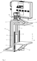
- figure 1 shows a preferred embodiment of a frame 1 of a welding device.
- the preferred frame 1 is used according to different preferred embodiments of the present invention in combination with a laser welder, or an infrared welder, or a vibration welder, or an ultrasonic welder, or a friction welder.
- the preferred embodiment of the frame 1 in figure 1 is shown without the welding device in order to be able to better illustrate the structural properties of the frame 1.
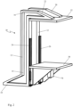
- the preferred frame 1 comprises a double frame 10 which has two vertical columns 12 arranged parallel to one another and next to one another.
- the vertical columns 12 are fixed at a lateral distance from one another on a base 18, here a plate.
- the base 18 ensures a stable and true-to-position arrangement of the vertical columns 12. While the lower end of the vertical columns 12, here the first end 14, is anchored in the base 18, adjacent to a second end 16 of the vertical columns 12, here the upper end of the Vertical columns 12, one cantilever arm 20, 22 is arranged on each vertical column 12.
- the cantilever arms 20, 22 are preferably formed integrally with the vertical columns 12 or are firmly connected to them.
- parallel guides 24 , 26 are provided on the vertical columns 12 . They are used to guide a movable table 30 or another component of the frame 1 or the welding device. Since the guides 24, 26 are attached to the vertical columns 12 and run parallel to the vertical columns, they serve to move a first table 30 in the direction of the fixed cantilever arms 20, 22.
- figure 1 shows the double frame 10 as an S-shaped combination of cantilever 20, 22, vertical column 12 and base 18. It is also preferred to realize the double frame 10 C-shaped. To this end, the base 18 preferably extends to parallel and adjacent or opposed relationship to the cantilever arms 20, 22.
- a second table 32 is fixed to the cantilever arms 20,22.
- the tables 30, 32 illustrate the possibility of arranging tools or machining components of the welding devices mentioned above. Such tools and processing components and their arrangement and use are generally known in the prior art.
- An oscillating structure with a sonotrode is preferably attached to the table 32 in an ultrasonic welding device.
- the movable table 30 with the counter tool and the material can be moved in the direction of the cantilever arms 20, 22 and the first table 32 in order to produce a welded connection between the lengths of material.
- the sonotrode (not shown) hits the material webs of the table 32 or the roller and welds them together.
- an oscillating head is preferably provided on the table 32 instead of the sonotrode.
- a laser source or a laser source is preferably on the table 32 instead of the sonotrode Infrared source provided.
- the table 30 supports the counter tool in this infrared welding device or the laser welding device, respectively.
- the table 32 with a friction weld drive to effect a friction weld connection.
- the movable table 30 forms the anvil or the counter-tool on which a component to be connected is arranged.
- the table 30 moves in the direction of the arrow 1.
- the table 32 is firmly attached to the cantilever arm 20,22.
- the table 32 is movably arranged while the table 30 is fixedly positioned.
- the table 32 is preferably guided parallel to the vertical columns 12 and on the vertical columns 12 via rails (not shown).
- both tables 30, 32 are movably arranged on the vertical columns 12.
- guides 24, 26 are provided for both tables 30, 32 so that they can be displaced parallel to the vertical columns 12.
- the vertical columns 12 in combination with the base 18 and cantilevers 20, 22 implement a constant orientation of the tables 30, 32 with respect to one another.
- the construction of the double frame 10 ensures that the vertical columns 12 are not bent up and thus the orientation of the tables 30, 32 relative to one another is disturbed.
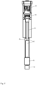
- a C-shaped drive unit 40 is provided for the preferred movement of one table 30 or both tables 30, 32 parallel to the vertical columns 12 (see FIG figure 1 and Figures 4-6 ).
- the drive unit 40 comprises a first 42 and a second flange 44 which are connected to one another via a vertical leg 50 .
- the first 42 and the second flange 44 are arranged transversely to the vertical leg 50 and parallel to one another.
- am Vertical leg 50 guides 52 are provided so that at least the first flange 42 is movable in the manner of a carriage relative to the second leg 44 and parallel to the vertical leg 50 .
- both flanges 42, 44 are preferably mounted as carriages, respectively, to move them relative to one another.
- the drive unit 40 has a linear drive 60, 62.
- the linear drive 60, 62 can include all common linear drives. This preferably includes a spindle drive in which one flange 42 is connected to the spindle and the other flange 44 is connected to the nut. In another preferred embodiment of the linear drive 60, 62, this is implemented as a hydraulic or pneumatic piston-cylinder drive. In addition, an electromagnetic drive can also be used as a linear drive 60, 62.
- the drive unit 40 is arranged between and parallel to the vertical columns 12 of the double frame 10 .
- the first flange 42 is positioned adjacent to the table 30 .
- the second flange 44 is positioned adjacent to the table 32 .
- the respective flange 42, 44 and the table 30, 32 adjacent thereto are non-rigidly connected to one another.
- a preferred construction for making this non-rigid connection is ball joints between flange 42, 44 and table 30, 32.
- the linear drive 60, 62 shortens in the infeed direction 1, the flanges 42, 44 are moved relative to one another. Accordingly, the movable table 30 is displaced toward the fixed table 32 to perform a welding operation.
- the table 30 is displaced in the direction of the cantilever arms 20, 22.
- the double frame 10 and the drive unit 40 are mechanically combined with one another in such a way that they are decoupled in terms of bending.
- the guidance of the tables 30, 32 and the stability of the double frame 10 with the vertical columns 12 ensure that the bending moment of the drive unit 40 cannot be transferred to the double frame 10.
- the double frame 10 and the drive unit 40 are arranged so that they are decoupled from one another in terms of bending.
- the two flanges 42, 44 are non-rigidly connected to the tables 30, 32, preferably via a ball and socket joint. In the same way, it is preferred to arrange only one of the tables 30, 32 or both tables 30, 32 to be movable along the vertical columns 12. In order to apply a sufficient welding force to the components and tools based on this design, it is sufficient if the force generated by the linear drive 60, 62 is not introduced centrally into the tables 30, 32 via the flanges 42, 44. Because of the construction of the frame 1, the parallel orientation of the plates 30, 32 to one another is maintained despite non-decentralized introduction of force. This means that there is no transfer of a possible flexing of the drive unit 40 to the double frame 10 .
- the moving table 30 in the double frame 10 is equipped with a known force measuring sensor 70 .
- the data from the force measuring sensor 70 is forwarded to an industrial computer (not shown) as a control unit. This also controls or regulates welding processes that are implemented using the frame 1 .
- the welding method of the present invention is described using a preferred embodiment as an example for the other known welding devices mentioned above.
- an oscillating structure with a sonotrode is attached to the fixed table 32 .
- the table 30 moves a counter-tool, for example an anvil or a roller, in the direction of the sonotrode in order to weld material between the sonotrode and the counter-tool to one another.
- a web of material or a first component is arranged on the first table 30 .
- the first component is then moved relative to a tool, here the sonotrode. It is equally preferred that the first component is moved against a further component in order to connect them to one another by means of ultrasound or another energy supply.
- both tables 30, 32 are moved. This can easily be implemented with the drive unit 40 described above.
- step C a mechanical load is applied to the component to be welded by further shortening the drive unit 40 . Since the component or the components are pressed against one another between the sonotrode and the counter-tool in combination with the tables 32 and 30, ultrasonic vibrations are impressed into the materials/components to be connected to one another.
- step D the mechanical stress during the welding is recorded with the aid of the force measuring sensor 70 mentioned above.
- alternative measurement options such as strain gauges or the like, instead of the force measurement sensor 70 .
- the drive unit 40 controls a removal of the sonotrode and the component or counter-tool from one another.
- the two tables 30, 32 also move away from one another accordingly.
- the welded component or workpiece is removed from the welding device.
Landscapes
- Engineering & Computer Science (AREA)
- Mechanical Engineering (AREA)
- Lining Or Joining Of Plastics Or The Like (AREA)
- Pressure Welding/Diffusion-Bonding (AREA)
Description
- Die vorliegende Erfindung betrifft eine Schweißvorrichtung, insbesondere eine Laserschweißvorrichtung, eine Infrarotschweißvorrichtung, eine Vibrationsschweißvorrichtung oder eine Ultraschallschweißvorrichtung, sowie ein Gestell zur Realisierung der genannten Schweißvorrichtung. Zudem betrifft vorliegende Erfindung ein Schweißverfahren, welches mit Hilfe der in oben genanntem Gestell angeordneten Schweißvorrichtung realisierbar ist.
- Im Stand der Technik sind verschiedene Konstruktionen eines Gestells für eine Schweißvorrichtung bekannt. Obwohl die oben genannten Schweißverfahren, wie das Laserschweißen, das Infrarotschweißen, das Vibrationsschweißen und das Ultraschallschweißen, im Hinblick auf die verbindende Energiezufuhr unterschiedlich ausgestaltet sind, zeichnen sich alle Verfahren dadurch aus, dass miteinander zu verbindende Bauteile gegeneinander gedrückt werden müssen. Entsprechend ist es erforderlich, dass in vertikaler Richtung auf das obere Bauteil in einer stapelförmigen Anordnung von mindestens zwei Bauteilen oder aber auch auf das untere Bauteil eine Kraft aufgebracht wird. Diese Kraft sorgt für den notwendigen Kontakt zwischen den miteinander zu verbindenden Bauteilen, sodass diese miteinander verbunden werden können.
- Die US-Patente
US 4,584,037 ,US 5,772,103 undUS 5,833,127 umfassen eine Vertikalsäule, an der über einen Kragarm eine Schweißvorrichtung vertikal versetzbar angeordnet ist. In den hier genannten Reibschweißvorrichtungen werden die Bauteile drehend gegeneinander gedrückt, um über die entstehende Reibung während des Drehens die nötige Wärme zum Verschweißen der beiden aneinander anliegenden Bauteile zu erzeugen. Dabei sorgt ein nötiger Druck oder eine durch das Gestell auf die beiden miteinander zu verbindenden Bauteile aufgebrachte Kraft dafür, dass sich eine verlässliche Schweißverbindung ausbildet. - Der oben angesprochene Druck/Kraft wirkt in gleicher Weise wie die Orientierung des Vertikalständers ebenfalls in vertikaler Richtung. Das hat zur Folge, dass bei ausreichender mechanischer Vertikalbelastung ein Aufbiegen bzw. Ausweichen des Vertikalständers aus seiner vertikalen Orientierung hervorgerufen wird. Dies ist im Speziellen dann der Fall, wenn die mechanische Belastung der Bauteile Lateralkräfte hervorruft, die gegen die Steifigkeit des Vertikalständers diesen in lateraler Richtung verformen. Entsprechend erfährt der Vertikalständer ein Biegemoment, sodass die miteinander zu verbindenden Bauteile aus ihrer parallelen Anordnung verkippt werden. Als eine Folge wird die zwischen den beiden Bauteilen erzeugte Schweißverbindung ungleichmäßig ausgebildet.
- Das deutsche Gebrauchsmuster
DE 83 16 643 beschreibt ein Gestell für Werkzeugmaschinen oder andere Bearbeitungsvorrichtungen. Das Gestell dieser Vorrichtung zeichnet sich dadurch aus, dass ein Spindelkasten zur Bewegung in z-Richtung, also in vertikaler Richtung, zum Bearbeiten eines Bauteils vorgesehen ist. Dieser Spindelkasten ist an zwei parallel zueinander angeordneten vertikalen Führungsschienen gehalten. Um diese vertikalen Führungsschienen mechanisch von der Gewichtskraft des Spindelkastens zu entlasten, ist zusätzlich zwischen diesen Führungen ein C-Träger mit Antriebseinheit angeordnet. Da der Spindelkasten nicht allein an den vertikalen Führungen, sondern ebenfalls an dem zwischengeordneten C-Träger aufgehangen ist, verteilen sich die mechanischen Gewichtskräfte des Spindelkastens auf die vertikalen Führungen und den C-Träger. Entsprechend werden die vertikalen Führungen von den quer dazu wirkenden Zugbelastungen des Spindelkastens entlastet, da ein Teil seiner Gewichtskraft über die zentrale Aufhängevorrichtung des C-Trägers aufgenommen wird. - Ein weiteres Gestell für eine Ultraschallschweißvorrichtung offenbart
EP 2 905 108 B1 . Dieses Gestell nutzt einen zentralen C-Träger, an dem zwei in vertikaler Richtung verfahrbare Kragarme in Form von Schlitten angeordnet sind. An dem oberen Kragarm bzw. Schlitten ist ein Linearantrieb vorgesehen, der eine Verstelleinheit für den darunter angeordneten Schlitten darstellt. Um den zentralen C-Träger mit Antrieb zu entlasten, sind seitlich davon C-förmige Bügel angeordnet. Diese C-förmige Bügel nehmen eine mögliche Aufbiegung des C-Trägers mit Antrieb auf. Auf diese Weise soll für eine parallele Anordnung von Sonotrode und Amboss gesorgt werden. - Häufig ist die mechanische Entlastung durch Nutzung der C-förmigen Bügel nicht ausreichend. Daher ist es zusätzlich erforderlich, die Antriebseinheit und das Schwinggebilde im vorliegenden Gestell fluchtend anzuordnen. Diese fluchtende Anordnung von Schwinggebilde und Antriebseinheit verhindert ein mögliches Biegemoment an dem Schlitten, der das Schwinggebilde trägt. Neben der aufwändigen Konstruktion sorgt gerade die zwingend erforderliche fluchtende Anordnung von Antriebseinheit und Schwinggebilde für die Bereitstellung eines großen Bauraums. Denn die Antriebseinheit ist oberhalb des Schwinggebildes angeordnet und ragt daher über das Schwinggebilde und das Gestell der Schweißvorrichtung hinaus.
- Ein Verfahren zum Heißverschweißen mit einer Heizplatten aufweisenden Maschine und eine Vorrichtung zum Auswechseln und Ausrichten der Heizplatten sind in
DE 26 35 348 A1 beschrieben. Die Maschine umfasst eine beheizte Platte auf einem beweglichen Schlitten, um in eine Position zwischen den zu verbindenden Teilen vorzurücken. Ersatzplatten sind in einer festen Gleitschiene im rechten Winkel zur Bewegungsrichtung des Schlittens montiert. In der eingefahrenen Position des Schlittens richtet sich ein Teil der Gleitschiene auf dem Schlitten nach der festen Schiene aus, so dass die frische Platte leicht in Position gebracht werden kann. Die Maschine wird verwendet, um Abdeckungen mit elektrischen Batteriegehäusen zu verbinden. Die Platten können schnell getauscht werden, ohne auf das Abkühlen der benutzten Platte zu warten. - Im Hinblick auf die Nachteile des Standes der Technik ist es die Aufgabe vorliegender Erfindung, eine alternative Konstruktion eines Gestells einer Schweißvorrichtung bereitzustellen, die sich durch ausreichende mechanische Stabilität aber auch durch eine Effektivität in ihrem Bauraum auszeichnet.
- Die obige Aufgabe wird durch ein Gestell für eine Schweißvorrichtung, insbesondere eine Laserschweißvorrichtung oder eine Infrarotschweißvorrichtung oder eine Vibrationsschweißvorrichtung oder eine Ultraschallschweißvorrichtung, gemäß dem unabhängigen Patentanspruch 1 gelöst. Zudem löst obige Aufgabe eine Schweißvorrichtung in Kombination mit obigem Gestell gemäß dem unabhängigen Patentanspruch 9 sowie die Verwendung des Gestells zum Laserschweißen, Infrarotschweißen, Vibrationsschweißen oder Ultraschallschweißen gemäß dem unabhängigen Patentanspruch 10. Außerdem wird obige Aufgabe durch das Schweißverfahren gemäß dem unabhängigen Patentanspruch 11 gelöst. Vorteilhafte Ausgestaltungen, Weiterentwicklungen und bevorzugte Ausführungsformen vorliegender Erfindung gehen aus der folgenden Beschreibung, den begleitenden Zeichnungen und den anhängenden Patentansprüchen hervor.
- Das erfindungsgemäße Gestell für eine Schweißvorrichtung, insbesondere eine Laserschweißvorrichtung oder eine Infrarotschweißvorrichtung oder eine Vibrationsschweißvorrichtung oder eine Ultraschallschweißvorrichtung, weist die folgenden Merkmale auf einen Doppelrahmen, der mindestens zwei auf einer Grundplatte befestigte sowie parallel zueinander und nebeneinander angeordnete Vertikalsäulen und jeweils einen an den Vertikalsäulen befestigten Kragarm aufweist, mindestens einen parallel zu den Vertikalsäulen versetzbaren Tisch, der parallel an den beiden Vertikalsäulen geführt ist, eine C-förmige Antriebseinheit, die einen ersten und einen zweiten Flansch umfasst, die relativ zueinander linear bewegbar an einem verbindenden Vertikalschenkel geführt sind, in der mit der Antriebseinheit ein Abstand zwischen dem ersten und dem zweiten Flansch in Richtung des Vertikalschenkels veränderbar ist, wobei die C-förmige Antriebseinheit zwischen den Vertikalsäulen des Doppelrahmens angeordnet ist und über eine Verbindung zwischen dem ersten Flansch und dem Tisch des Doppelrahmens der Tisch relativ gegen ein starres Gegenlager oder gegen einen weiteren bewegbaren Tisch des Doppelrahmens bewegbar ist, wobei das Gegenlager oder der zweite Tisch mit dem zweiten Flansch verbunden ist.
- Das Gestell vorliegender Erfindung zeichnet sich durch die mechanisch entkoppelte Kombination und verschachtelte Anordnung verschiedener Last aufnehmender Konstruktionen für Fügevorrichtungen mit einer vertikalen Lasteinbringung aus. Um zunächst miteinander zu verbindende Bauteile oder Werkzeug und Bauteil in vertikaler Richtung aufeinanderzu bewegen zu können, ist der genannte Doppelrahmen vorgesehen. Dieser führt die Bauteile oder Werkzeuge oder Schwinggebilde oder dergleichen in vertikaler Richtung aufeinander zu. Dabei bilden die seitlich von den beiden Vertikalsäulen weg ragenden Kragarme, die vorzugsweise quer zu den Vertikalsäulen angeordnet sind, eine mechanische Stütze für die bewegten Bauteile, Werkzeuge und dergleichen. Denn diese beiden Kragarme, die parallel zueinander angeordnet sind und bewegt werden oder starr angeordnet sind und gemeinsam einen Tisch tragen, liefern aufgrund ihrer Konstruktion gerade in Kombination mit einer Grundplatte, einem Gegenlager oder einem weiteren bewegten Tisch die Gegenkraft für eine aufzubringende Schweißkraft.
- Dabei zeichnet sich die Konstruktion des Doppelrahmens dadurch aus, dass er aufgrund seiner Stabilität und seiner mechanischen Entkoppelung von der Last erzeugenden Antriebseinheit nicht zu Verformungen während eines Schweißvorgangs neigt. Dies stellt sicher, dass er während des Schweißvorgangs die beiden miteinander zu verbindenden Bauteile oder die Anordnung von Schwinggebilde und Amboss oder die Anordnung von Werkzeug und Gegenlager in ihrer Orientierung zueinander sicher gehalten sind. Denn die Antriebseinheit ist nicht starr mit den relativ zueinander bewegten Komponenten, wie Tisch, Gegenlager, verbunden. Selbst wenn daher die Antriebseinheit aufgrund der Belastung ein Aufbiegemoment erfährt, überträgt sich das Aufbiegemoment nicht auf den Doppelrahmen.
- Um aber den zumindest einen versetzbaren Tisch, der am Doppelrahmen geführt ist, zum Schweißen zu führen und die nötige Schweißkraft aufzubringen, ist die C-förmige Antriebseinheit zwischengeordnet im Doppelrahmen angeordnet. Diese C-förmige Antriebseinheit dient somit der Aufbringung der Schweißkraft über den versetzbaren Tisch auf die zwischen dem versetzbaren Tisch und dem Gegenlager angeordneten Bauteile oder/und Werkzeuge oder/und Schwinggebilde oder dergleichen. Während der Doppelrahmen für die definierte Orientierung des bewegten Tisches und/oder des Gegenlagers und/oder des Werkzeugs und/oder des Schwinggebildes und/oder der Bauteile und/oder eines weiteren bewegten Tisches sorgt, erzeugt die C-förmige Antriebseinheit die für das Schweißen erforderliche Kraft in vertikaler Richtung oder parallel zu den Vertikalsäulen. Sollte dabei eine eventuell aufgebrachte Schweißkraft dazu führen, dass die C-fönnige Antriebseinheit trotz ihrer Steifigkeit aufgebogen wird, dann ist dieses aufbiegende Moment auf die C-förmige Antriebseinheit beschränkt. Entsprechend wird trotz des Aufbiegens der C-fönnigen Antriebseinheit die Anordnung der miteinander zu verbindenden Bauteile oder die Anordnung von Werkzeug und Gegenlager oder von Schwinggebilde und Gegenlager usw. nicht beeinträchtigt. Selbst wenn die C-förmige Antriebseinheit bis an ihre Leistungsgrenze belastet wird und sich während einer Aufbringung einer Schweißkraft aufbiegt, führt dies nicht zu nachteiligen Auswirkungen auf die herzustellende Schweißverbindung.
- Gemäß einer bevorzugten Ausführungsform des erfindungsgemäßen Gestells ist die Verbindung zwischen dem ersten Flansch und dem Tisch beweglich konstruiert. Gemäß einer weiteren bevorzugten Ausführungsform vorliegender Erfindung ist die Verbindung zwischen dem zweiten Flansch und dem weiteren Tisch oder dem Gegenlager beweglich ausgeführt. Beweglich bedeutet in diesem Zusammenhang, dass Verformungen und/oder Bewegungen der Antriebseinheit nicht auf den Doppelrahmen übertragen werden. Es handelt sich somit um eine mechanische Lasten übertragende Verbindung.
- Aus obiger Konstruktion folgt, dass eine nicht-starre Verbindung zwischen dem von dem Vertikalschenkel der C-förmigen Antriebseinheit weg ragenden Flansch und dem mit dem Flansch verbundenen Tisch genutzt wird. Dies gilt in gleicher Weise für die mechanische Verbindung zwischen dem zweiten Flansch und einem Gegenlager und/oder einem weiteren bewegten Tisch und/oder einer anderen Verbindung zwischen dem zweiten Flansch und einer weiteren Konstruktionskomponente. Aufgrund dieser bevorzugt nicht-starren Verbindung zwischen dem jeweiligen Flansch und der durch diesen Flansch zu bewegenden oder zu stützenden Konstruktionskomponente ist gewährleistet, dass ein Aufbiegen der C-förmigen Antriebseinheit erfolgen kann. Dieses Aufbiegen beeinträchtigt aufgrund der nicht-starren Verbindung gerade nicht die mechanische Kopplung und somit die Krafteinleitung in den bewegten Tisch und das Gegenlager oder den weiteren bewegten Tisch des Doppelrahmens. Denn selbst wenn aufgrund der Aufbiegung der C-förmigen Antriebseinheit eine Krafteinleitung von dieser Antriebseinheit nicht senkrecht in den bewegten Tisch erfolgt, wird eine für ein Schweißen ausreichende Vertikalkomponente der Schweißkraft auf den bewegten Tisch bzw. das Werkzeug usw. übertragen. Aufgrund dieser Konstruktion ist gewährleistet, dass die C-förmige Antriebseinheit die notwendige Schweißkraft in vertikaler Richtung bereitstellt, ohne dabei jedoch eine Ausrichtung der miteinander zu verbindenden Bauteile oder der miteinander kooperierenden Maschinenkomponenten zu stören.
- Gemäß einer weiteren bevorzugten Ausführungsform vorliegender Erfindung ist mit der C-förmigen Antriebseinheit der mindestens eine Tisch des Doppelrahmens aufbiegungsentkoppelt gegen den weiteren Tisch oder das Gegenlager derart bewegbar, dass ein Aufbiegen des Gestells, insbesondere des Doppelrahmens, aufgrund mechanischer Lasten in Richtung parallel zu den Vertikalsäulen auf die C-förmige Antriebseinheit beschränkt, vorzugsweise verhindert, ist.
- Gemäß einer weiteren bevorzugten Ausführungsform vorliegender Erfindung tragen die Kragarme einen fest angeordneten zweiten Tisch, vorzugsweise eine Werkzeugaufnahme, gegen den der erste Tisch bewegbar ist.
- Gemäß unterschiedlicher Anforderungen an die mithilfe des Gestells zu realisierenden Schweißvorrichtung werden bevorzugt unterschiedliche Bewegungskonzepte in dem Doppelrahmen realisiert. Gemäß einer Alternative sind bevorzugt die Kragarme in vertikaler Richtung benachbart zum oberen Ende der Vertikalsäulen fest angeordnet. An ihnen stützt sich ein bevorzugt quer zu den Vertikalsäulen verlaufender Tisch in fester Anordnung ab, sodass für einen Schweißvorgang ein Werkzeug oder ein bewegter Tisch gegen diesen fest angeordneten zweiten Tisch bewegt werden kann.
- Da sowohl der fest angeordnete Tisch wie auch der bewegbare Tisch an den Vertikalsäulen des Doppelrahmens geführt sind, besitzen diese beiden aufeinanderzu bewegten Tische vorzugsweise eine parallele Ausrichtung zueinander.
- Es ist ebenfalls bevorzugt, je nach Geometrie der miteinander zu verbindenden Bauteile oder entsprechend einer Geometrie von verwendetem Schwinggebilde und Gegenlager oder von verwendetem Werkzeug und Gegenwerkzeug oder Gegenlager eine nicht-parallele Ausrichtung der beiden aufeinanderzu bewegten Tische zu wählen. Insgesamt soll durch die gezielte Orientierung der aufeinanderzu bewegbaren Tische sichergestellt sein, dass diese eine optimale Anordnung und Ausrichtung der miteinander zu verbindenden Bauteile unterstützen. Zudem wird aufgrund der Anordnung dieser bewegbaren Tische in der mechanisch stabilen Konstruktion des Doppelrahmens gewährleistet, dass die Orientierung der miteinander zu verbindenden Bauteile trotz Aufbringung einer Schweißkraft und vorzugsweise konstant gewährleistet ist. Denn eine durch die mechanische Belastung der Schweißkraft möglicherweise erzeugte Aufbiegung wird durch die C-förmige Antriebseinheit allein aufgenommen, während der Doppelrahmen seine Form aufrechterhält.
- Gemäß einer weiteren bevorzugten Ausführungsform des erfindungsgemäßen Gestells sind der erste Flansch über ein Kugelgelenk mit dem zweiten Tisch und der zweite Flansch über ein Kugelgelenk mit dem ersten Tisch verbunden, wobei vorzugsweise der erste und der zweite Flansch quer zum Vertikalschenkel angeordnet sind.
- Gemäß der oben beschriebenen bevorzugten Ausführungsform des erfindungsgemäßen Gestells ist gewährleistet, dass trotz einer möglichen Aufbiegung der C-förmigen Antriebseinheit eine verlässliche Schweißkraft in die miteinander zu verbindenden Bauteile, die Tische oder Werkzeuge eingeleitet wird. Dabei ist wesentlich, dass die aufeinanderzu relativ bewegbaren Tische in ihrer Orientierung nicht durch die mögliche Aufbringung der C-förmigen Antriebseinheit beeinträchtigt werden. Entsprechend ist für die Verbindung zwischen dem ersten und dem zweiten Flansch der C-förmigen Antriebseinheit und dem angrenzend angeordneten Tisch oder Werkzeug oder anderen Komponenten der Schweißvorrichtung ein Kugelgelenk vorgesehen. Natürlich ist es analog ebenfalls bevorzugt, eine andere mechanische Kopplung zwischen dem Flansch und dem Tisch zu nutzen, die eine Entkopplung zwischen dem Tisch und einer möglichen Aufbiegung der C-förmigen Antriebseinheit sicherstellt. Die Entkoppelung entkoppelt eine Aufbiegungsbewegung der Antriebseinheit vom Doppelrahmen, insbesondere von relativ zueinander bewegten Komponenten des Doppelrahmens.
- Gemäß einer weiteren bevorzugten Ausführungsform vorliegender Erfindung ist an dem mindestens einen bewegbaren Tisch des Doppelrahmens ein Kraftmesssensor vorgesehen. Analog dazu ist es ebenfalls bevorzugt, eine zu einem Kraftmesssensor alternative Vorrichtung mit Gestell anzuwenden, mit der ebenfalls verlässlich eine mechanische Belastung während eines Schweißvorgangs erfassbar ist.
- Gemäß einer weiteren bevorzugten Ausführungsform des erfindungsgemäßen Gestells weisen der erste und der zweite Flansch der C-förmigen Antriebseinheit einen ersten und einen zweiten Schlitten auf, die auf einer Führung entlang des Vertikalschenkels gelagert und linear bewegbar geführt sind. Diese Schlitten übertragen die für Schweißvorgänge erforderliche Bewegung auf die relativ zueinander bewegbaren Teile des Doppelrahmens. Zudem übertragen diese Schlitten die erforderliche Schweißkraft auf die im Doppelrahmen angeordneten Bauteile oder Werkzeuge oder Schwinggebilde und Gegenwerkzeug usw. Es ist bevorzugt, dass auch die hier beschriebenen Schlitten nicht-starr mit den relativ zueinander bewegbaren Tischen oder ähnlichen Anordnungen des Doppelrahmens verbunden sind. Denn nur diese nicht-starre Verbindung gewährleistet, dass ein mögliches Aufbiegen der C-förmigen Antriebseinheit gerade nicht über die Schlitten auf die herzustellende Schweißverbindung übertragen wird.
- Vorliegende Erfindung umfasst zudem eine Schweißvorrichtung in Kombination mit dem oben beschriebenen Gestell. Diese Schweißvorrichtung nutzt eine Laserschweißvorrichtung oder eine Infrarotschweißvorrichtung oder eine Vibrationsschweißvorrichtung oder eine Ultraschallschweißvorrichtung oder eine Rotationsreibschweißvorrichtung.
- Des Weiteren umfasst vorliegende Erfindung die Verwendung des Gestells gemäß einer der oben beschriebenen bevorzugten Ausführungsformen zum Laserschweißen oder Infrarotschweißen oder Vibrationsschweißen oder Ultraschallschweißen oder Rotationsreibschweißen.
- Vorliegende Erfindung umfasst zudem ein Schweißverfahren für eine der oben beschriebenen Schweißvorrichtungen. Dieses Schweißverfahren weist die folgenden Schritte auf: Anordnen mindestens eines ersten Bauteils auf dem ersten Tisch, relatives Bewegen des ersten Bauteils gegen ein Werkzeug oder ein zweites Bauteil, welches mit einem Gegenlager oder einem weiteren bewegbaren Tisch verbunden ist, wobei der erste und der zweite Flansch der C-förmigen Antriebseinheit aufeinanderzu bewegt werden, während des Schweißen Aufnehmen oder Aufbringen einer mechanischen Last von oder auf das erste Bauteil durch die C-förmige Antriebseinheit.
- Da das erfindungsgemäße Schweißverfahren das oben beschriebene Gestell in Kombination mit einer Schweißvorrichtung verwendet, werden die für das Schweißen erforderlichen mechanischen Lasten über die C-förmige Antriebseinheit auf die Bauteile aufgebracht. Da bereits die oben beschriebene mechanische Entkopplung zwischen der C-förmigen Antriebseinheit und dem Doppelrahmen konstruktiv realisiert ist, ist auch das Schweißverfahren dadurch ausgezeichnet, dass sich ein aufbiegendes Moment auf die C-förmige Antriebseinheit beschränkt. Entsprechend wird der Doppelrahmen nicht durch ein Biegemoment belastet.
- Gemäß einer weiteren bevorzugten Ausführungsform des erfindungsgemäßen Schweißverfahrens findet der folgende Schritt statt: Erfassen mechanischer Lasten am Bauteil mithilfe mindestens eines Kraftmesssensors in Kombination mit dem ersten Tisch oder mithilfe von Dehnmessstreifen an der C-förmigen Antriebseinheit.
- Zudem ist es erfindungsgemäß bevorzugt, das Schweißverfahren mit dem folgenden zusätzlichen Schritt durchzuführen: Einleiten einer mechanischen Last der C-förmigen Antriebseinheit über nicht-starre Verbindungen in den ersten Tisch und/oder das Gegenlager oder den zweiten Tisch, sodass trotz der Aufbiegung der C-förmigen Antriebseinheit das Verschweißen nicht beeinträchtigt ist.
- Die vorliegende Erfindung wurde unter Bezugnahme auf die begleitenden Zeichnungen näher erläutert. Es zeigen:
- Figur 1
- eine perspektivische schematische Darstellung einer bevorzugten Ausführungsform des erfindungsgemäßen Gestells vorliegender Erfindung,
- Figur 2
- eine bevorzugte Ausführungsform des Doppelrahmens des erfindungsgemäßen Gestells in einer perspektivischen Darstellung,
- Figur 3
- eine Darstellung des Doppelrahmens aus
Figur 2 in einer Draufsicht, - Figur 4
- eine Seitenansicht einer bevorzugten Ausführungsform der Antriebseinheit des erfindungsgemäßen Gestells vorliegender Erfindung,
- Figur 5
- eine Draufsicht auf die Antriebseinheit gemäß
Figur 4 , - Figur 6
- eine perspektivische Ansicht der Antriebseinheit aus
Figur 4 und - Figur 7
- ein Flussdiagramm einer bevorzugten Ausführungsform des Schweißverfahrens gemäß vorliegender Erfindung.
-
Figur 1 zeigt eine bevorzugte Ausführungsfonn eines Gestells 1 einer Schweißvorrichtung. Das bevorzugte Gestell 1 wird gemäß unterschiedlicher bevorzugter Ausführungsformen vorliegender Erfindung in Kombination mit einer Laserschweißvorrichtung oder einer Infrarotschweißvorrichtung oder einer Vibrationsschweißvorrichtung oder einer Ultraschallschweißvorrichtung oder einer Reibschweißvorrichtung verwendet. - Die bevorzugte Ausführungsform des Gestells 1 in
Figur 1 ist ohne Schweißvorrichtung gezeigt, um die konstruktiven Eigenschaften des Gestells 1 besser veranschaulichen zu können. - Das bevorzugte Gestell 1 umfasst einen Doppelrahmen 10, der zwei parallel zueinander und nebeneinander angeordnete Vertikalsäulen 12 aufweist. Die Vertikalsäulen 12 sind mit einem seitlichen Abstand zueinander fest an einer Basis 18, hier eine Platte, befestigt. Die Basis 18 gewährleistet eine stabile und positionsgetreue Anordnung der Vertikalsäulen 12. Während das untere Ende der Vertikalsäulen 12, hier das erste Ende 14, in der Basis 18 verankert ist, sind benachbart zu einem zweiten Ende 16 der Vertikalsäulen 12, hier das obere Ende der Vertikalsäulen 12, jeweils ein Kragarm 20, 22 an jeder Vertikalsäule 12 angeordnet. Die Kragarme 20, 22 sind vorzugsweise integral mit den Vertikalsäulen 12 ausgebildet oder fest mit diesen verbunden.
- Gemäß einer bevorzugten Ausführungsform vorliegender Erfindung sind an den Vertikalsäulen 12 parallele Führungen 24, 26 vorgesehen. Sie dienen der Führung eines bewegbaren Tisches 30 oder einer anderen Komponente des Gestells 1 oder der Schweißvorrichtung. Da die Führungen 24, 26 an den Vertikalsäulen 12 befestigt sind und parallel zu den Vertikalsäulen verlaufen, dienen sie der Bewegung eines ersten Tisches 30 in Richtung der fest angeordneten Kragarme 20, 22.
- Die bevorzugte Ausführungsform der
Figur 1 zeigt den Doppelrahmen 10 als S-förmige Kombination aus Kragarm 20, 22, Vertikalsäule 12 und Basis 18. Es ist ebenfalls bevorzugt, den Doppelrahmen 10 C-förmig zu realisieren. Zu diesem Zweck erstreckt sich vorzugsweise die Basis 18 bis zu einer parallelen und benachbarten bzw. gegenüberliegenden Anordnung zu den Kragarmen 20, 22. - Gemäß einer bevorzugten Ausführungsform vorliegender Erfindung ist an den Kragarmen 20, 22 ein zweiter Tisch 32 fest angeordnet. Die Tische 30, 32 veranschaulichen die Anordnungsmöglichkeit von Werkzeugen oder Bearbeitungskomponenten der oben genannten Schweißvorrichtungen. Derartige Werkzeuge und Bearbeitungskomponenten sowie deren Anordnung und Verwendung sind im Stand der Technik allgemein bekannt.
- Vorzugsweise ist in einer Ultraschallschweißvorrichtung ein Schwinggebilde mit Sonotrode am Tisch 32 befestigt. Zwei miteinander zu verbindende Bauteile, beispielsweise zwei Stoffbahnen, laufen bevorzugt über den bewegbaren Tisch 30, der somit auch eine Walze oder ein Gegenwerkzeug darstellen kann. Zum Herstellen einer Schweißverbindung zwischen den Stoffbahnen ist der bewegbare Tisch 30 mit dem Gegenwerkzeug und dem Material in Richtung Kragarme 20, 22 und erster Tisch 32 verfahrbar. Bei dieser Bewegung trifft die Sonotrode (nicht gezeigt) auf die Materialbahnen des Tisches 32 bzw. der Walze und verschweißt es miteinander.
- In einer bevorzugten analogen Anordnung einer Vibrationsschweißmaschine ist vorzugsweise am Tisch 32 anstelle der Sonotrode ein Schwingkopf vorgesehen.
- In einer weiteren bevorzugten Anordnung einer Infrarotschweißvorrichtung oder einer Laserschweißvorrichtung ist bevorzugt am Tisch 32 anstelle der Sonotrode eine Laserquelle oder eine Infrarotquelle vorgesehen. Der Tisch 30 trägt entsprechend das Gegenwerkzeug in dieser Infrarotschweißvorrichtung oder der Laserschweißvorrichtung.
- In gleicher Weise ist es bevorzugt, den Tisch 32 mit einem Reibschweißantrieb auszustatten, um eine Reibschweißverbindung herzustellen. Der verfahrbare Tisch 30 bildet in diesem Fall den Amboss oder das Gegenwerkzeug, auf dem ein zu verbindendes Bauteil angeordnet ist.
- Während die obigen Anordnungen Beispiele darstellen, ist es in gleicher Weise möglich, die Anordnung an den Tischen 30, 32 zu tauschen. Denn die beiden Tische 30, 32 führen eine Relativbewegung in Verlaufsrichtung der Vertikalsäule 12 durch, die zu einer Schweißverbindung oder zu einem Lösen der Werkzeuge nach einem Schweißen führt.
- Gemäß der bevorzugten Ausführungsform der
Figur 1 bewegt sich der Tisch 30 in Richtung des Pfeils 1. Der Tisch 32 ist fest am Kragarm 20, 22 befestigt. - Es ist ebenfalls bevorzugt, dass der Tisch 32 bewegbar angeordnet ist, während der Tisch 30 fest positioniert ist. Zu diesem Zweck ist der Tisch 32 bevorzugt über Schienen (nicht gezeigt) parallel zu den Vertikalsäulen 12 und an den Vertikalsäulen 12 geführt.
- Gemäß einer weiteren bevorzugten Ausführungsform vorliegender Erfindung sind beide Tische 30, 32 bewegbar an den Vertikalsäulen 12 angeordnet. Zu diesem Zweck sind Führungen 24, 26 für beide Tische 30, 32 vorgesehen, sodass sie parallel zu den Vertikalsäulen 12 versetzbar sind.
- Die Vertikalsäulen 12 in Kombination mit der Basis 18 und den Kragarmen 20, 22 realisieren eine konstante Orientierung der Tische 30, 32 mit Bezug zueinander. Gleichzeitig dazu stellt die Konstruktion des Doppelrahmens 10 sicher, dass die Vertikalsäulen 12 nicht aufgebogen und damit die Orientierung der Tische 30, 32 zueinander gestört wird.
- Zur bevorzugten Bewegung eines Tisches 30 oder beider Tische 30, 32 parallel zu den Vertikalsäulen 12 ist eine C-förmige Antriebseinheit 40 vorgesehen (siehe
Figur 1 undFiguren 4-6 ). - Die Antriebseinheit 40 umfasst einen ersten 42 und einen zweiten Flansch 44, die über einen Vertikalschenkel 50 miteinander verbunden sind. Vorzugsweise sind der erste 42 und der zweite Flansch 44 quer zum Vertikalschenkel 50 und parallel zueinander angeordnet. Zudem sind am Vertikalschenkel 50 Führungen 52 vorgesehen, sodass zumindest der erste Flansch 42 nach Art eines Schlittens relativ zum zweiten Schenkel 44 und parallel zum Vertikalschenkel 50 bewegbar ist.
- Es ist ebenfalls bevorzugt, beide Flansche 42, 44 jeweils als Schlitten anzuordnen, um sie relativ zueinander zu bewegen.
- Zur Bewegung mindestens eines Flansches 42, 44 relativ zum anderen Flansch 44, 42 weist die Antriebseinheit 40 einen Linearantrieb 60, 62 auf. Der Linearantrieb 60, 62 kann alle gängigen Linearantriebe umfassen. Dazu zählt bevorzugt ein Spindeltrieb, bei dem ein Flansch 42 mit der Spindel und der andere Flansch 44 mit der Mutter verbunden ist. In einer anderen bevorzugten Ausgestaltung des Linearantriebs 60, 62 ist dieser als ein hydraulischer oder pneumatischer Kolben-Zylinder-Antrieb realisiert. Zudem ist auch ein elektromagnetischer Antrieb als Linearantrieb 60, 62 einsetzbar.
- Wie man anhand der bevorzugten Ausführungsform in
Figur 1 erkennen kann, ist die Antriebseinheit 40 zwischen den und parallel zu den Vertikalsäulen 12 des Doppelrahmens 10 angeordnet. In dieser Anordnung ist der erste Flansch 42 benachbart zum Tisch 30 positioniert. Der zweite Flansch 44 ist benachbart zum Tisch 32 angeordnet. Vorzugsweise sind der jeweilige Flansch 42, 44 und der dazu benachbarte Tisch 30, 32 nicht-starr miteinander verbunden. - Eine bevorzugte Konstruktion zur Herstellung dieser nicht-starren Verbindung sind Kugelgelenke zwischen Flansch 42, 44 und Tisch 30, 32.
- Verkürzt sich der Linearantrieb 60, 62 in Zustellrichtung 1, werden die Flansche 42, 44 relativ aufeinanderzu bewegt. Entsprechend wird der bewegbare Tisch 30 in Richtung des fest angeordneten Tisches 32 versetzt, um einen Schweißvorgang durchzuführen.
- Unabhängig davon, ob nur ein Flansch 42 oder beide Flansche 42, 44 über den Linearantrieb 60, 62 versetzbar angeordnet sind, wird der Tisch 30 in Richtung der Kragarme 20, 22 versetzt.
- Wie sich aus obiger Beschreibung ergibt, sind der Doppelrahmen 10 und die Antriebseinheit 40 derart mechanisch miteinander kombiniert, dass sie aufbiegungsentkoppelt sind. Das bedeutet, dass die Antriebseinheit 40 mechanische Kräfte auf die Tische 30, 32 zu deren Relativbewegung aufbringt, die zu einem möglichen Aufbiegen der Antriebseinheit 40 führen können. Gleichzeitig stellt die Führung der Tische 30, 32 und die Stabilität des Doppelrahmens 10 mit den Vertikalsäulen 12 sicher, dass das Aufbiegemoment der Antriebseinheit 40 nicht auf den Doppelrahmen 10 übertragbar ist. Entsprechend sind der Doppelrahmen 10 und die Antriebseinheit 40 aufbiegungsentkoppelt zueinander angeordnet.
- Wie oben bereits erwähnt worden ist, sind die beiden Flansche 42, 44 mit den Tischen 30, 32 nicht-starr, vorzugsweise über ein Kugelgelenk, verbunden. Dabei ist in gleicher Weise bevorzugt, nur einen der Tische 30, 32 oder beide Tische 30, 32 entlang der Vertikalsäulen 12 bewegbar anzuordnen. Um basierend auf dieser Konstruktion eine ausreichende Schweißkraft auf die Bauteile und Werkzeuge aufzubringen, ist es ausreichend, wenn die durch den Linearantrieb 60,62 erzeugte Kraft über die Flansche 42, 44 nicht zentral in die Tische 30, 32 eingeleitet wird. Denn durch die Konstruktion des Gestells 1 bleibt trotz nicht dezentraler Krafteinleitung die parallele Orientierung der Teller 30, 32 zueinander erhalten. Das bedeutet, es findet keine Übertragung einer möglichen Aufbiegung der Antriebseinheit 40 auf den Doppelrahmen 10 statt.
- Zur Erfassung einer Schweißkraft wird der bewegte Tisch 30 im Doppelrahmen 10 mit einem bekannten Kraftmesssensor 70 ausgestattet. Die Daten des Kraftmesssensors 70 werden an einen Industriecomputer (nicht gezeigt) als Steuereinheit weitergeleitet. Dieser übernimmt auch eine Steuerung oder Regelung von Schweißprozessen, die mithilfe des Gestells 1 realisiert werden.
- Anhand einer Ultraschallschweißvorrichtung in Kombination mit dem bevorzugten Gestell 1 wird das Schweißverfahren vorliegender Erfindung anhand einer bevorzugten Ausführungsform beispielgebend für die anderen oben genannten bekannten Schweißvorrichtungen beschrieben. Dazu wird davon ausgegangen, dass am fest angeordneten Tisch 32 ein Schwinggebilde mit Sonotrode befestigt ist. Der Tisch 30 bewegt ein Gegenwerkzeug, beispielsweise einen Amboss oder eine Walze, in Richtung Sonotrode, um Material zwischen Sonotrode und Gegenwerkzeug miteinander zu verschweißen.
- Entsprechend wird in einem ersten Schritt A eine Materialbahn oder ein erstes Bauteil auf dem ersten Tisch 30 angeordnet. In einem zweiten Schritt B erfolgt dann das relative Bewegen des ersten Bauteils gegen ein Werkzeug, hier die Sonotrode. Es ist in gleicher Weise bevorzugt, dass das erste Bauteil gegen ein weiteres Bauteil bewegt wird, um diese mittels Ultraschall oder einer anderen Energiezufuhr miteinander zu verbinden. Im Zusammenhang mit der Relativbewegung im Schritt B des ersten Bauteils zur Sonotrode ist es in gleicher Weise bevorzugt, dass beide Tische 30, 32 bewegt werden. Dies ist ohne weiteres mit der oben beschriebenen Antriebseinheit 40 realisierbar.
- Im darauffolgenden Schritt C erfolgt durch ein weiteres Verkürzen der Antriebseinheit 40 das Aufbringen einer mechanischen Last auf das zu verschweißende Bauteil. Da das Bauteil bzw. die Bauteile zwischen Sonotrode und Gegenwerkzeug in Kombination mit den Tischen 32 und 30 gegeneinander gedrückt werden, werden Ultraschallschwingungen in die miteinander zu verbindenden Materialien/Bauteile eingeprägt. Während dieses Schweißvorgangs wird im Schritt D die mechanische Belastung während des Schweißens mithilfe des oben angesprochenen Kraftmesssensors 70 erfasst. In diesem Zusammenhang ist es ebenfalls bevorzugt, anstelle des Kraftmesssensors 70 alternative Messmöglichkeiten, wie beispielsweise Dehnmessstreifen oder dergleichen, einzusetzen.
- Nachdem die Schweißverbindung hergestellt worden ist, wird über die Antriebseinheit 40 ein Entfernen der Sonotrode und des Bauteils bzw. Gegenwerkzeugs voneinander angesteuert. Entsprechend entfernen sich auch die beiden Tische 30, 32 relativ voneinander.
- Sobald dies erfolgt ist, wird das verschweißte Bauteil bzw. Werkstück der Schweißvorrichtung entnommen.
-
- 1
- Gestell
- 10
- Doppelrahmen
- 12
- Vertikalsäule
- 14
- erstes Ende
- 16
- zweites Ende
- 18
- Basis
- 20, 22
- Kragarme
- 44,26
- Führungen
- 30
- bewegbarer Tisch
- 32
- Tisch
- 40
- Antriebseinheit
- 42, 44
- Flansch
- 50
- Vertikalschenkel
- 52
- Führungen
- 60, 62
- Linearantrieb
- 70
- Kraftmesssensor
Claims (13)
- Gestell (1) für eine Schweißvorrichtung, insbesondere eine Laserschweißvorrichtung oder eine Infrarotschweißvorrichtung oder eine Vibrationsschweißvorrichtung oder eine Ultraschallschweißvorrichtung, welches die folgenden Merkmale aufweist:a. einen Doppelrahmen (10), der mindestens zwei auf einer Grundplatte (18) befestigte sowie parallel zueinander und nebeneinander angeordnete Vertikalsäulen (12) und jeweils einen an den Vertikalsäulen (12) befestigten Kragarm (20, 22) aufweist,b. mindestens einen parallel zu den Vertikalsäulen (12) versetzbaren Tisch (30), der parallel an den beiden Vertikalsäulen (12) geführt ist,c. eine C-förmige Antriebseinheit (40), die einen ersten (42) und einen zweiten Flansch (44) umfasst, die relativ zueinander linear bewegbar an einem verbindenden Vertikalschenkel (50) geführt sind, in der mit der Antriebseinheit (40) ein Abstand zwischen dem ersten (42) und dem zweiten Flansch (44) in Richtung des Vertikalschenkels (50) veränderbar ist, wobeid. die C-förmige Antriebseinheit (40) zwischen den Vertikalsäulen (12) des Doppelrahmens (10) angeordnet ist unde. über eine Verbindung zwischen dem ersten Flansch (42) und dem Tisch (30) des Doppelrahmens (10) der Tisch (30) relativ gegen ein starres Gegenlager (32) oder gegen einen weiteren bewegbaren Tisch des Doppelrahmens (10) bewegbar ist, wobei das Gegenlager (32) oder der zweite Tisch mit dem zweiten Flansch (44) verbunden ist.
- Gestell (1) nach Patentanspruch 1, in welchem die Verbindung zwischen dem ersten Flansch (42) und dem Tisch (30) beweglich ist.
- Gestell (1) nach Patentanspruch 2, in welchem die Verbindung zwischen dem zweiten Flansch (44) und dem weiteren Tisch (32) oder dem Gegenlager beweglich ist.
- Gestell (1) gemäß einem der vorhergehenden Patentansprüche, in welchem mit der C-förmigen Antriebseinheit (40) der mindestens eine Tisch (30) des Doppelrahmens (10) aufbiegungsentkoppelt gegen den weiteren Tisch (32) oder das Gegenlager derart bewegbar ist, dass ein Aufbiegen des Gestells (1) aufgrund mechanischer Lasten in Richtung parallel zu den Vertikalsäulen (12) auf die C-förmige Antriebseinheit (40) beschränkt ist.
- Gestell (1) gemäß einem der vorhergehenden Patentansprüche, in welchem die Kragarme (20, 22) einen fest angeordneten zweiten Tisch (32), vorzugsweise eine Werkzeugaufnahme, tragen, gegen den der erste Tisch (30) relativ bewegbar ist.
- Gestell (1) gemäß Patentanspruch 5, in welchem der erste Flansch (42) über ein Kugelgelenk mit dem ersten Tisch (30) und der zweite Flansch (44) über ein Kugelgelenk mit dem zweiten Tisch (32) verbunden ist, wobei vorzugsweise der erste (42) und zweite Flansch (44) quer zum Vertikalschenkel (50) angeordnet sind.
- Gestell (1) gemäß einem der vorhergehenden Patentansprüche, in welchem an dem mindestens einen bewegbaren Tisch (30) des Doppelrahmens (10) ein Kraftmesssensor angeordnet ist.
- Gestell (1) gemäß einem der vorhergehenden Patentansprüche, in welchem der erste (42) und der zweite Flansch (44) der C-förmigen Antriebseinheit (40) aus einem ersten und einem zweiten Schlitten bestehen, die auf einer Führung (52) entlang des Vertikalschenkels (50) gelagert und linear bewegbar geführt sind.
- Schweißvorrichtung in Kombination mit dem Gestell (1) gemäß einem der Patentansprüche 1 bis 8, die umfassen:eine Laserschweißvorrichtung odereine Infrarotschweißvorrichtung odereine Vibrationsschweißvorrichtung odereine Ultraschallschweißvorrichtung.
- Verwendung des Gestells (1) gemäß einem der vorhergehenden Patentansprüche 1-8 zum Laserschweißen, Infrarotschweißen, Vibrationsschweißen oder Ultraschallschweißen.
- Schweißverfahren mit einer Schweißvorrichtung gemäß dem unabhängigen Patentanspruch 9, welches die folgenden Schritte aufweist:a. Anordnen (Schritt A) mindestens eines ersten Bauteils auf dem ersten Tisch (30),b. relatives Bewegen (B) des ersten Bauteils gegen ein Werkzeug oder ein zweites Bauteil, welches mit einem Gegenlager oder einem weiteren bewegbaren Tisch (32) verbunden ist, wobei der erste (42) und der zweite Flansch (44) der C-förmigen Antriebseinheit (40) aufeinander zubewegt werden,c. während des Schweißens Aufbringen (C) einer mechanischen Last auf das erste Bauteil durch die C-förmige Antriebseinheit (40).
- Schweißverfahren gemäß Patentanspruch 11 mit dem weiteren Schritt:
Erfassen (D) mechanischer Lasten am Bauteil mithilfe mindestens eines Kraftmesssensors in Kombination mit dem ersten Tisch (30) oder mithilfe von Dehnmessstreifen an der C-förmigen Antriebseinheit (40). - Schweißverfahren gemäß Patentanspruch 11 oder 12, mit dem weiteren Schritt:
Einleiten einer mechanischen Last der C-förmigen Antriebseinheit (40) über nicht-starre Verbindungen in den ersten Tisch (30) und/oder das Gegenlager oder den zweiten Tisch (32), sodass trotz Aufbiegung der C-förmigen Antriebseinheit (40) das Verschweißen nicht beeinträchtigt ist.
Applications Claiming Priority (2)
| Application Number | Priority Date | Filing Date | Title |
|---|---|---|---|
| DE102018119618.0A DE102018119618A1 (de) | 2018-08-13 | 2018-08-13 | Schweißvorrichtung und Gestell dafür |
| PCT/EP2019/070796 WO2020035326A1 (de) | 2018-08-13 | 2019-08-01 | Schweissvorrichtung und gestell dafür |
Publications (2)
| Publication Number | Publication Date |
|---|---|
| EP3820679A1 EP3820679A1 (de) | 2021-05-19 |
| EP3820679B1 true EP3820679B1 (de) | 2023-07-12 |
Family
ID=67544241
Family Applications (1)
| Application Number | Title | Priority Date | Filing Date |
|---|---|---|---|
| EP19749704.3A Active EP3820679B1 (de) | 2018-08-13 | 2019-08-01 | Schweissvorrichtung und gestell dafür |
Country Status (4)
| Country | Link |
|---|---|
| EP (1) | EP3820679B1 (de) |
| DE (1) | DE102018119618A1 (de) |
| ES (1) | ES2958119T3 (de) |
| WO (1) | WO2020035326A1 (de) |
Families Citing this family (2)
| Publication number | Priority date | Publication date | Assignee | Title |
|---|---|---|---|---|
| CN111673488A (zh) * | 2020-06-13 | 2020-09-18 | 浙江力扬威亚智能装备有限公司 | 一种数控机床用交换工作台 |
| CN115972589A (zh) * | 2022-12-19 | 2023-04-18 | 江苏大学 | 一种双向可精确调整的超声辅助激光连接装置 |
Family Cites Families (8)
| Publication number | Priority date | Publication date | Assignee | Title |
|---|---|---|---|---|
| DE2635348C3 (de) * | 1976-08-03 | 1981-04-09 | General Battery Corp., Reading, Pa. | Maschine zum Stumpfschweißen von Formteilen aus thermoplastischem Werkstoff |
| CS201349B1 (en) * | 1978-10-09 | 1980-10-31 | Vaclav Smrha | Facility for decreasing the deformation of the stands and frames of machines |
| US4584037A (en) | 1982-09-07 | 1986-04-22 | Cosden Technology, Inc. | Inertial spin welding of thermoplastic and thermoplastic coated container parts |
| EP0113389A1 (de) * | 1982-12-10 | 1984-07-18 | MDC Max Dätwyler Bleienbach AG | Vorrichtung zum Entlasten der Führung für zumindest in im wesentlichen vertikaler Richtung bewegbare Bauteile, insbesondere von Bearbeitungsmaschinen, wie beispielsweise Werkzeugmaschinen |
| US5772103A (en) | 1996-09-25 | 1998-06-30 | Hofius, Sr.; David V. | Method and apparatus for friction torque welding |
| US5833127A (en) | 1996-12-12 | 1998-11-10 | Powell Mcgee Associates, Inc. | Method and apparatus for precision spin-welding |
| DE102014101627A1 (de) * | 2014-02-10 | 2015-08-13 | Ms Spaichingen Gmbh | Gestell für eine Maschine |
| DE102016102164A1 (de) * | 2016-02-08 | 2017-08-10 | Ms Ultraschall Technologie Gmbh | Ultraschall-Bearbeitungsmaschine |
-
2018
- 2018-08-13 DE DE102018119618.0A patent/DE102018119618A1/de not_active Withdrawn
-
2019
- 2019-08-01 EP EP19749704.3A patent/EP3820679B1/de active Active
- 2019-08-01 WO PCT/EP2019/070796 patent/WO2020035326A1/de not_active Ceased
- 2019-08-01 ES ES19749704T patent/ES2958119T3/es active Active
Also Published As
| Publication number | Publication date |
|---|---|
| DE102018119618A1 (de) | 2020-02-13 |
| WO2020035326A1 (de) | 2020-02-20 |
| EP3820679A1 (de) | 2021-05-19 |
| ES2958119T3 (es) | 2024-02-01 |
Similar Documents
| Publication | Publication Date | Title |
|---|---|---|
| EP2424724B1 (de) | Ultraschallsiegelvorrichtung und verfahren zum versiegeln von materialbahnen | |
| EP2905108B1 (de) | Gestell für eine Maschine | |
| DE4495551C2 (de) | Z-Achsen-Antrieb für eine Werkzeugmaschine | |
| EP2416940B1 (de) | Vorrichtung zum bearbeiten eines packstoffs mittels ultraschall | |
| EP2783791B1 (de) | Positioniereinrichtung in Portalbauweise | |
| EP3154722B1 (de) | Biegepresse mit biegeeinheit sowie verfahren zur umformung | |
| AT523568B1 (de) | Biegemaschine | |
| DE69321827T2 (de) | Kombiniertes schneid- und schweissverfahren zur herstellung struktureller produkte, gerät zur durchführung eines solchen verfahrens und mittels dieses verfahrens hergestellter produkte | |
| DE2209845A1 (de) | Meßgerät, insbesondere Lagerung für Meßfühler | |
| DE9319146U1 (de) | Vorrichtung zum Schweißen und/oder Schneiden | |
| EP3210709B1 (de) | Ultraschall-bearbeitungsmaschine | |
| EP1607165A1 (de) | Vorrichtung zum Verbinden von Werkstücken nach der Methode des Reibrührschweissens mit einem Werkzeug bestehend aus zwei gegensinnig rotierbar ausgeführten Schultern | |
| EP3552729B1 (de) | Stanznietvorrichtung | |
| EP2846966B1 (de) | Transferzentrum zur spanenden bearbeitung mindestens eines werkstücks, mit einem positionsausgleichssystem | |
| EP3112083B1 (de) | Portalanordnung einer werkzeugmaschine und werkzeugmaschine mit einer derartigen portalanordnung | |
| EP3160726B1 (de) | Verbesserte c-gestell-presse | |
| EP2495069B1 (de) | Werkzeugmaschine mit einem Werkstücktisch | |
| EP3231585A1 (de) | Vorichtung zum ultraschallschweissen | |
| EP3820679A1 (de) | Schweissvorrichtung und gestell dafür | |
| EP2887513B1 (de) | Linearmotoranordnung und Werkzeugmaschine mit einer Linearmotoranordnung | |
| EP3481565B1 (de) | Streckbiegemaschine und verfahren zum verformen eines werkstückes | |
| EP0499019B1 (de) | Widerstandsschweissmaschine, insbesondere zum Abbrennstumpfschweissen von Schienen | |
| EP1941956A1 (de) | Anbiegepresse zum Biegen eines Blechs bei der Herstellung eines Rohres | |
| EP1632308A1 (de) | Linearbewegungsführung mit zwei parallelen Führungsschienen und Verfahren zu deren Herstellung | |
| EP1849591B1 (de) | Presse |
Legal Events
| Date | Code | Title | Description |
|---|---|---|---|
| STAA | Information on the status of an ep patent application or granted ep patent |
Free format text: STATUS: UNKNOWN |
|
| STAA | Information on the status of an ep patent application or granted ep patent |
Free format text: STATUS: THE INTERNATIONAL PUBLICATION HAS BEEN MADE |
|
| PUAI | Public reference made under article 153(3) epc to a published international application that has entered the european phase |
Free format text: ORIGINAL CODE: 0009012 |
|
| STAA | Information on the status of an ep patent application or granted ep patent |
Free format text: STATUS: REQUEST FOR EXAMINATION WAS MADE |
|
| 17P | Request for examination filed |
Effective date: 20210215 |
|
| AK | Designated contracting states |
Kind code of ref document: A1 Designated state(s): AL AT BE BG CH CY CZ DE DK EE ES FI FR GB GR HR HU IE IS IT LI LT LU LV MC MK MT NL NO PL PT RO RS SE SI SK SM TR |
|
| DAV | Request for validation of the european patent (deleted) | ||
| DAX | Request for extension of the european patent (deleted) | ||
| GRAP | Despatch of communication of intention to grant a patent |
Free format text: ORIGINAL CODE: EPIDOSNIGR1 |
|
| STAA | Information on the status of an ep patent application or granted ep patent |
Free format text: STATUS: GRANT OF PATENT IS INTENDED |
|
| INTG | Intention to grant announced |
Effective date: 20230301 |
|
| GRAS | Grant fee paid |
Free format text: ORIGINAL CODE: EPIDOSNIGR3 |
|
| GRAA | (expected) grant |
Free format text: ORIGINAL CODE: 0009210 |
|
| STAA | Information on the status of an ep patent application or granted ep patent |
Free format text: STATUS: THE PATENT HAS BEEN GRANTED |
|
| AK | Designated contracting states |
Kind code of ref document: B1 Designated state(s): AL AT BE BG CH CY CZ DE DK EE ES FI FR GB GR HR HU IE IS IT LI LT LU LV MC MK MT NL NO PL PT RO RS SE SI SK SM TR |
|
| P01 | Opt-out of the competence of the unified patent court (upc) registered |
Effective date: 20230601 |
|
| REG | Reference to a national code |
Ref country code: CH Ref legal event code: EP |
|
| REG | Reference to a national code |
Ref country code: DE Ref legal event code: R096 Ref document number: 502019008518 Country of ref document: DE |
|
| REG | Reference to a national code |
Ref country code: IE Ref legal event code: FG4D Free format text: LANGUAGE OF EP DOCUMENT: GERMAN |
|
| PGFP | Annual fee paid to national office [announced via postgrant information from national office to epo] |
Ref country code: GB Payment date: 20230822 Year of fee payment: 5 Ref country code: ES Payment date: 20230918 Year of fee payment: 5 Ref country code: CH Payment date: 20230902 Year of fee payment: 5 |
|
| REG | Reference to a national code |
Ref country code: LT Ref legal event code: MG9D |
|
| REG | Reference to a national code |
Ref country code: NL Ref legal event code: MP Effective date: 20230712 |
|
| PGFP | Annual fee paid to national office [announced via postgrant information from national office to epo] |
Ref country code: FR Payment date: 20230823 Year of fee payment: 5 |
|
| PG25 | Lapsed in a contracting state [announced via postgrant information from national office to epo] |
Ref country code: NL Free format text: LAPSE BECAUSE OF FAILURE TO SUBMIT A TRANSLATION OF THE DESCRIPTION OR TO PAY THE FEE WITHIN THE PRESCRIBED TIME-LIMIT Effective date: 20230712 |
|
| PG25 | Lapsed in a contracting state [announced via postgrant information from national office to epo] |
Ref country code: GR Free format text: LAPSE BECAUSE OF FAILURE TO SUBMIT A TRANSLATION OF THE DESCRIPTION OR TO PAY THE FEE WITHIN THE PRESCRIBED TIME-LIMIT Effective date: 20231013 |
|
| PG25 | Lapsed in a contracting state [announced via postgrant information from national office to epo] |
Ref country code: IS Free format text: LAPSE BECAUSE OF FAILURE TO SUBMIT A TRANSLATION OF THE DESCRIPTION OR TO PAY THE FEE WITHIN THE PRESCRIBED TIME-LIMIT Effective date: 20231112 |
|
| PG25 | Lapsed in a contracting state [announced via postgrant information from national office to epo] |
Ref country code: SE Free format text: LAPSE BECAUSE OF FAILURE TO SUBMIT A TRANSLATION OF THE DESCRIPTION OR TO PAY THE FEE WITHIN THE PRESCRIBED TIME-LIMIT Effective date: 20230712 Ref country code: RS Free format text: LAPSE BECAUSE OF FAILURE TO SUBMIT A TRANSLATION OF THE DESCRIPTION OR TO PAY THE FEE WITHIN THE PRESCRIBED TIME-LIMIT Effective date: 20230712 Ref country code: PT Free format text: LAPSE BECAUSE OF FAILURE TO SUBMIT A TRANSLATION OF THE DESCRIPTION OR TO PAY THE FEE WITHIN THE PRESCRIBED TIME-LIMIT Effective date: 20231113 Ref country code: NO Free format text: LAPSE BECAUSE OF FAILURE TO SUBMIT A TRANSLATION OF THE DESCRIPTION OR TO PAY THE FEE WITHIN THE PRESCRIBED TIME-LIMIT Effective date: 20231012 Ref country code: LV Free format text: LAPSE BECAUSE OF FAILURE TO SUBMIT A TRANSLATION OF THE DESCRIPTION OR TO PAY THE FEE WITHIN THE PRESCRIBED TIME-LIMIT Effective date: 20230712 Ref country code: LT Free format text: LAPSE BECAUSE OF FAILURE TO SUBMIT A TRANSLATION OF THE DESCRIPTION OR TO PAY THE FEE WITHIN THE PRESCRIBED TIME-LIMIT Effective date: 20230712 Ref country code: IS Free format text: LAPSE BECAUSE OF FAILURE TO SUBMIT A TRANSLATION OF THE DESCRIPTION OR TO PAY THE FEE WITHIN THE PRESCRIBED TIME-LIMIT Effective date: 20231112 Ref country code: HR Free format text: LAPSE BECAUSE OF FAILURE TO SUBMIT A TRANSLATION OF THE DESCRIPTION OR TO PAY THE FEE WITHIN THE PRESCRIBED TIME-LIMIT Effective date: 20230712 Ref country code: GR Free format text: LAPSE BECAUSE OF FAILURE TO SUBMIT A TRANSLATION OF THE DESCRIPTION OR TO PAY THE FEE WITHIN THE PRESCRIBED TIME-LIMIT Effective date: 20231013 Ref country code: FI Free format text: LAPSE BECAUSE OF FAILURE TO SUBMIT A TRANSLATION OF THE DESCRIPTION OR TO PAY THE FEE WITHIN THE PRESCRIBED TIME-LIMIT Effective date: 20230712 |
|
| PGFP | Annual fee paid to national office [announced via postgrant information from national office to epo] |
Ref country code: IT Payment date: 20231103 Year of fee payment: 5 Ref country code: DE Payment date: 20231025 Year of fee payment: 5 |
|
| REG | Reference to a national code |
Ref country code: ES Ref legal event code: FG2A Ref document number: 2958119 Country of ref document: ES Kind code of ref document: T3 Effective date: 20240201 |
|
| PG25 | Lapsed in a contracting state [announced via postgrant information from national office to epo] |
Ref country code: PL Free format text: LAPSE BECAUSE OF FAILURE TO SUBMIT A TRANSLATION OF THE DESCRIPTION OR TO PAY THE FEE WITHIN THE PRESCRIBED TIME-LIMIT Effective date: 20230712 |
|
| REG | Reference to a national code |
Ref country code: DE Ref legal event code: R097 Ref document number: 502019008518 Country of ref document: DE |
|
| PG25 | Lapsed in a contracting state [announced via postgrant information from national office to epo] |
Ref country code: LU Free format text: LAPSE BECAUSE OF NON-PAYMENT OF DUE FEES Effective date: 20230801 |
|
| PG25 | Lapsed in a contracting state [announced via postgrant information from national office to epo] |
Ref country code: SM Free format text: LAPSE BECAUSE OF FAILURE TO SUBMIT A TRANSLATION OF THE DESCRIPTION OR TO PAY THE FEE WITHIN THE PRESCRIBED TIME-LIMIT Effective date: 20230712 Ref country code: RO Free format text: LAPSE BECAUSE OF FAILURE TO SUBMIT A TRANSLATION OF THE DESCRIPTION OR TO PAY THE FEE WITHIN THE PRESCRIBED TIME-LIMIT Effective date: 20230712 Ref country code: LU Free format text: LAPSE BECAUSE OF NON-PAYMENT OF DUE FEES Effective date: 20230801 Ref country code: EE Free format text: LAPSE BECAUSE OF FAILURE TO SUBMIT A TRANSLATION OF THE DESCRIPTION OR TO PAY THE FEE WITHIN THE PRESCRIBED TIME-LIMIT Effective date: 20230712 Ref country code: DK Free format text: LAPSE BECAUSE OF FAILURE TO SUBMIT A TRANSLATION OF THE DESCRIPTION OR TO PAY THE FEE WITHIN THE PRESCRIBED TIME-LIMIT Effective date: 20230712 Ref country code: CZ Free format text: LAPSE BECAUSE OF FAILURE TO SUBMIT A TRANSLATION OF THE DESCRIPTION OR TO PAY THE FEE WITHIN THE PRESCRIBED TIME-LIMIT Effective date: 20230712 Ref country code: MC Free format text: LAPSE BECAUSE OF FAILURE TO SUBMIT A TRANSLATION OF THE DESCRIPTION OR TO PAY THE FEE WITHIN THE PRESCRIBED TIME-LIMIT Effective date: 20230712 Ref country code: SK Free format text: LAPSE BECAUSE OF FAILURE TO SUBMIT A TRANSLATION OF THE DESCRIPTION OR TO PAY THE FEE WITHIN THE PRESCRIBED TIME-LIMIT Effective date: 20230712 |
|
| REG | Reference to a national code |
Ref country code: BE Ref legal event code: MM Effective date: 20230831 |
|
| PLBE | No opposition filed within time limit |
Free format text: ORIGINAL CODE: 0009261 |
|
| STAA | Information on the status of an ep patent application or granted ep patent |
Free format text: STATUS: NO OPPOSITION FILED WITHIN TIME LIMIT |
|
| REG | Reference to a national code |
Ref country code: IE Ref legal event code: MM4A |
|
| 26N | No opposition filed |
Effective date: 20240415 |
|
| PG25 | Lapsed in a contracting state [announced via postgrant information from national office to epo] |
Ref country code: IE Free format text: LAPSE BECAUSE OF NON-PAYMENT OF DUE FEES Effective date: 20230801 |
|
| PG25 | Lapsed in a contracting state [announced via postgrant information from national office to epo] |
Ref country code: IE Free format text: LAPSE BECAUSE OF NON-PAYMENT OF DUE FEES Effective date: 20230801 Ref country code: SI Free format text: LAPSE BECAUSE OF FAILURE TO SUBMIT A TRANSLATION OF THE DESCRIPTION OR TO PAY THE FEE WITHIN THE PRESCRIBED TIME-LIMIT Effective date: 20230712 |
|
| PG25 | Lapsed in a contracting state [announced via postgrant information from national office to epo] |
Ref country code: BE Free format text: LAPSE BECAUSE OF NON-PAYMENT OF DUE FEES Effective date: 20230831 |
|
| PG25 | Lapsed in a contracting state [announced via postgrant information from national office to epo] |
Ref country code: BG Free format text: LAPSE BECAUSE OF FAILURE TO SUBMIT A TRANSLATION OF THE DESCRIPTION OR TO PAY THE FEE WITHIN THE PRESCRIBED TIME-LIMIT Effective date: 20230712 |
|
| PG25 | Lapsed in a contracting state [announced via postgrant information from national office to epo] |
Ref country code: BG Free format text: LAPSE BECAUSE OF FAILURE TO SUBMIT A TRANSLATION OF THE DESCRIPTION OR TO PAY THE FEE WITHIN THE PRESCRIBED TIME-LIMIT Effective date: 20230712 |
|
| REG | Reference to a national code |
Ref country code: DE Ref legal event code: R119 Ref document number: 502019008518 Country of ref document: DE |
|
| REG | Reference to a national code |
Ref country code: CH Ref legal event code: PL |
|
| GBPC | Gb: european patent ceased through non-payment of renewal fee |
Effective date: 20240801 |
|
| PG25 | Lapsed in a contracting state [announced via postgrant information from national office to epo] |
Ref country code: CH Free format text: LAPSE BECAUSE OF NON-PAYMENT OF DUE FEES Effective date: 20240831 |
|
| PG25 | Lapsed in a contracting state [announced via postgrant information from national office to epo] |
Ref country code: DE Free format text: LAPSE BECAUSE OF NON-PAYMENT OF DUE FEES Effective date: 20250301 |
|
| PG25 | Lapsed in a contracting state [announced via postgrant information from national office to epo] |
Ref country code: GB Free format text: LAPSE BECAUSE OF NON-PAYMENT OF DUE FEES Effective date: 20240801 |
|
| PG25 | Lapsed in a contracting state [announced via postgrant information from national office to epo] |
Ref country code: IT Free format text: LAPSE BECAUSE OF NON-PAYMENT OF DUE FEES Effective date: 20240801 |
|
| PG25 | Lapsed in a contracting state [announced via postgrant information from national office to epo] |
Ref country code: FR Free format text: LAPSE BECAUSE OF NON-PAYMENT OF DUE FEES Effective date: 20240831 |
|
| PG25 | Lapsed in a contracting state [announced via postgrant information from national office to epo] |
Ref country code: CY Free format text: LAPSE BECAUSE OF FAILURE TO SUBMIT A TRANSLATION OF THE DESCRIPTION OR TO PAY THE FEE WITHIN THE PRESCRIBED TIME-LIMIT; INVALID AB INITIO Effective date: 20190801 |
|
| PG25 | Lapsed in a contracting state [announced via postgrant information from national office to epo] |
Ref country code: HU Free format text: LAPSE BECAUSE OF FAILURE TO SUBMIT A TRANSLATION OF THE DESCRIPTION OR TO PAY THE FEE WITHIN THE PRESCRIBED TIME-LIMIT; INVALID AB INITIO Effective date: 20190801 |
|
| REG | Reference to a national code |
Ref country code: ES Ref legal event code: FD2A Effective date: 20250926 |
|
| PG25 | Lapsed in a contracting state [announced via postgrant information from national office to epo] |
Ref country code: ES Free format text: LAPSE BECAUSE OF NON-PAYMENT OF DUE FEES Effective date: 20240802 |
|
| REG | Reference to a national code |
Ref country code: AT Ref legal event code: MM01 Ref document number: 1586674 Country of ref document: AT Kind code of ref document: T Effective date: 20240801 |
|
| PG25 | Lapsed in a contracting state [announced via postgrant information from national office to epo] |
Ref country code: AT Free format text: LAPSE BECAUSE OF NON-PAYMENT OF DUE FEES Effective date: 20240801 |
|
| PG25 | Lapsed in a contracting state [announced via postgrant information from national office to epo] |
Ref country code: TR Free format text: LAPSE BECAUSE OF FAILURE TO SUBMIT A TRANSLATION OF THE DESCRIPTION OR TO PAY THE FEE WITHIN THE PRESCRIBED TIME-LIMIT Effective date: 20230712 |
|
| PGFP | Annual fee paid to national office [announced via postgrant information from national office to epo] |
Ref country code: AT Payment date: 20260410 Year of fee payment: 5 |