EP3821776B1 - Staubsaugerfilterbeutel für einen handstaubsauger - Google Patents
Staubsaugerfilterbeutel für einen handstaubsauger Download PDFInfo
- Publication number
- EP3821776B1 EP3821776B1 EP19208499.4A EP19208499A EP3821776B1 EP 3821776 B1 EP3821776 B1 EP 3821776B1 EP 19208499 A EP19208499 A EP 19208499A EP 3821776 B1 EP3821776 B1 EP 3821776B1
- Authority
- EP
- European Patent Office
- Prior art keywords
- vacuum cleaner
- bag
- filter bag
- holding plate
- cleaner filter
- Prior art date
- Legal status (The legal status is an assumption and is not a legal conclusion. Google has not performed a legal analysis and makes no representation as to the accuracy of the status listed.)
- Active
Links
Images



Classifications
-
- A—HUMAN NECESSITIES
- A47—FURNITURE; DOMESTIC ARTICLES OR APPLIANCES; COFFEE MILLS; SPICE MILLS; SUCTION CLEANERS IN GENERAL
- A47L—DOMESTIC WASHING OR CLEANING; SUCTION CLEANERS IN GENERAL
- A47L5/00—Structural features of suction cleaners
- A47L5/12—Structural features of suction cleaners with power-driven air-pumps or air-compressors, e.g. driven by motor vehicle engine vacuum
- A47L5/22—Structural features of suction cleaners with power-driven air-pumps or air-compressors, e.g. driven by motor vehicle engine vacuum with rotary fans
- A47L5/24—Hand-supported suction cleaners
-
- A—HUMAN NECESSITIES
- A47—FURNITURE; DOMESTIC ARTICLES OR APPLIANCES; COFFEE MILLS; SPICE MILLS; SUCTION CLEANERS IN GENERAL
- A47L—DOMESTIC WASHING OR CLEANING; SUCTION CLEANERS IN GENERAL
- A47L9/00—Details or accessories of suction cleaners, e.g. mechanical means for controlling the suction or for effecting pulsating action; Storing devices specially adapted to suction cleaners or parts thereof; Carrying-vehicles specially adapted for suction cleaners
- A47L9/10—Filters; Dust separators; Dust removal; Automatic exchange of filters
- A47L9/14—Bags or the like; Rigid filtering receptacles; Attachment of, or closures for, bags or receptacles
-
- A—HUMAN NECESSITIES
- A47—FURNITURE; DOMESTIC ARTICLES OR APPLIANCES; COFFEE MILLS; SPICE MILLS; SUCTION CLEANERS IN GENERAL
- A47L—DOMESTIC WASHING OR CLEANING; SUCTION CLEANERS IN GENERAL
- A47L9/00—Details or accessories of suction cleaners, e.g. mechanical means for controlling the suction or for effecting pulsating action; Storing devices specially adapted to suction cleaners or parts thereof; Carrying-vehicles specially adapted for suction cleaners
- A47L9/10—Filters; Dust separators; Dust removal; Automatic exchange of filters
- A47L9/14—Bags or the like; Rigid filtering receptacles; Attachment of, or closures for, bags or receptacles
- A47L9/1427—Means for mounting or attaching bags or filtering receptacles in suction cleaners; Adapters
- A47L9/1436—Connecting plates, e.g. collars, end closures
Definitions
- the invention relates to a vacuum cleaner filter bag, in particular a vacuum cleaner filter bag for a handheld vacuum cleaner and/or a so-called stick vacuum cleaner, in particular for cordless models.
- Stick vacuum cleaners are usually, but not always, cordless devices (battery-powered vacuum cleaners) in which an electric brush is connected to the actual housing of the handheld vacuum cleaner via a suction pipe without a suction hose. These devices are very light and handy.
- the sticks have low power consumption in the range of around 150 to 600 W.
- the volume flows achieved are correspondingly low and are in the order of 10 to 30 l/s.
- the filter housing is typically cylindrical and has a small volume (approx. 1 to 2 liters).
- a cyclone separator is usually used as a filter. The cyclone separator accelerates the suction air and the particles it contains. This consumes a significant part of the available power and there is little power left to generate a sufficient volume flow.
- the cleaning effect dust absorption is often unsatisfactory.
- a holding plate for a vacuum cleaner bag which can be reversibly connected to the vacuum cleaner bag, whereby the outer contour of the holding plate can be adapted to the contour of the holding plate present in a vacuum cleaner.
- the EP 2 772 173 A1 discloses a filter bag for a vacuum cleaner, wherein a filter material is fixed to a plate-shaped part, while a collar is fixed to the plate-shaped part within a circular inlet opening.
- the collar can be connected to the filter material and the plate-shaped part at a single annular seam, thus only one connection point is provided.
- a filter bag made of modern nonwoven laminates separates dust much more energy efficiently. However, it is difficult to produce a filter bag that fits perfectly into the very small space available and provides a sufficient filter surface.
- the object of the invention is therefore to provide a vacuum cleaner filter bag that can be produced simply and automatically, in particular a vacuum cleaner filter bag for a handheld vacuum cleaner and/or a stick vacuum cleaner, which can use the available installation space as optimally as possible.
- the invention therefore provides a vacuum cleaner filter bag comprising a bag wall and a holding plate, wherein the holding plate comprises a nozzle which is at least partially cylindrical and extends in the direction of the through-opening formed in the holding plate, wherein the bag wall is connected along the circumference of the nozzle to the outer surface of the nozzle.
- the bag wall is connected to the holding plate via the at least partially cylindrical nozzle and to the outer surface of the nozzle along the circumference, the complex formation of a base during production, which is otherwise often only possible manually, is no longer necessary. This means that the vacuum cleaner filter bag according to the invention can be manufactured more efficiently.
- the vacuum cleaner filter bag can be intended in particular for handheld vacuum cleaners and/or a so-called stick vacuum cleaner, in particular for cordless models.
- the filling volume can therefore be between 0.5 and 3 liters, in particular between 0.5 and 2 liters, when fully unfolded.
- the holding plate of the vacuum cleaner filter bag can be attached to a holding device in a vacuum cleaner housing.
- the holding plate can be arranged, in particular fixed, in a predetermined position in the vacuum cleaner housing.
- the bag wall provided with a corresponding opening is put over the at least partially cylindrical nozzle of the holding plate and connected to its outer surface.
- the vacuum cleaner filter bag extends essentially parallel to the longitudinal axis of the nozzle and thus in the inflow direction through the through opening of the holding plate into the bag.
- the vacuum cleaner filter bag is better adapted to the usual filter housing of handheld vacuum cleaners and/or stick vacuum cleaners, which is typically cylindrical and has the holding device for the holding plate on one of the cover surfaces of the cylinder.
- the at least partially cylindrical nozzle thus encompasses the through-opening of the retaining plate, so that an inflow opening is formed through which dust-laden air can flow during operation can flow into the interior of the vacuum cleaner filter bag.
- the longitudinal axis of the nozzle is defined here as the direction in which the through-opening in the nozzle runs. This direction is in particular perpendicular to the plane in which a connecting plate of the holding plate is arranged, which can be connected to a holding device of the vacuum cleaner.
- Cylindrical at least in sections means that the nozzle comprises at least one section that is in the shape of a cylinder, i.e. defined by a surface area and two boundary surfaces.
- the cylindrical shape is not limited to a circular cylinder.
- the cross section of the cylindrical section i.e. the guide curve of the general cylinder, can have any shape.
- the cross section of the cylindrical section can also be a polygon. In this case, one can also speak of a prism-shaped section.
- the cylindrical section can in particular have the shape of a straight or vertical cylinder, with the surface lines running parallel to the longitudinal axis of the nozzle.
- the nozzle can comprise a second section, in particular adjacent to the cylindrical section, with a circumference that is larger than the cylindrical section.
- the second section can in particular protrude outwards beyond the outer surface of the cylindrical section.
- This second section can correspond to the connecting plate of the holding plate or be part of it.
- the connecting plate can in particular be a flat component, in particular where its extension in two directions (length, width) is significantly larger, in particular at least three times larger, than in a direction perpendicular thereto (thickness).
- the connecting plate can in particular completely surround the through opening of the holding plate.
- the through opening of the holding plate can in particular extend through the connecting plate and the nozzle.
- the holding plate can comprise one or more plastics or consist of one or more plastics.
- recycled plastics can be used, such as recycled polypropylene, rPP, and/or recycled polyethylene terephthalate, rPET.
- the holding plate can comprise a closure element for closing the inlet opening. This allows the suction material to be retained inside the bag, particularly when the bag is removed.
- the retaining plate is made in one piece with the nozzle.
- the retaining plate and the nozzle are therefore a single component.
- the retaining plate can be designed as an injection-molded part or as a part produced by thermoforming.
- the retaining plate can also be manufactured partly by injection molding and partly by thermoforming.
- the retaining plate can also comprise a sealing lip surrounding the through-opening.
- the sealing lip can comprise or consist of a thermoplastic elastomer, for example based on polypropylene.
- the sealing lip is intended to prevent or limit the escape of dust from the vacuum cleaner filter bag by sealing the area between the inner edge of the through-opening and the outside of a connection piece of the vacuum cleaner.
- the bag wall is made of an air-permeable material and can be constructed in several layers. In the latter case, this is also referred to as a laminate. Several layers of the laminate, in particular each layer of the laminate, can include or consist of a nonwoven fabric and/or a fiber fleece.
- plastics can be used as material for the bag wall, in particular for one or more layers of nonwoven fabric or nonwoven fabric, for example polypropylene and/or polyester.
- the bag wall can also contain or consist of recycled plastic and/or recycled material from the manufacture of textiles (textile left-over - TLO).
- the plastic recyclates can be unmetallized.
- One example of this is plastic flakes or chips recovered from PET beverage bottles.
- the plastic recyclates can also be metallized, e.g. if the recyclates were obtained from metallic plastic films, in particular metallized PET films (MPET).
- MPET metallized PET films
- Recycled polyethylene terephthalate can be obtained, for example, from beverage bottles, in particular from so-called bottle flakes, i.e. pieces of ground beverage bottles.
- the recycled plastics in particular recycled PET and/or recycled PP, both in the metallized and non-metallized version, can be spun into the corresponding fibers from which the corresponding staple fibers or meltblown or spunbond nonwovens can be produced for the purposes of the present invention.
- Recycled material from the manufacture of textiles arises in particular during the processing of textile materials (in particular textile fibers and filaments, as well as linear, flat and spatial textile structures made with them), such as the manufacture (including carding, spinning, cutting and drying) or recycling of textile materials.
- textile materials in particular textile fibers and filaments, as well as linear, flat and spatial textile structures made with them
- manufacture including carding, spinning, cutting and drying
- recycling of textile materials These powdery and/or fibrous materials represent waste materials that can settle on the machines or filter materials used to process the textiles.
- the dust (powder) or fibers are normally disposed of and thermally recycled.
- the powdered and/or fibrous recycled material is therefore, for example, production waste; this applies in particular to material that is a waste product during the carding, spinning, cutting or drying of textile materials. In this case, it is also referred to as "pre-consumer waste”.
- the recycled material from the manufacture of textiles, TLO can therefore include in particular fibres and/or filaments obtained from waste materials from the textile and clothing industry, from post-consumer waste (textiles and similar) and/or from products collected for recycling.
- a nonwoven fabric is a randomly arranged fabric that has undergone a consolidation step so that it has sufficient strength to be wound up or unwound into rolls, for example by machine (i.e. on an industrial scale).
- the minimum web tension required for winding is 0.044 N/mm.
- the web tension should not be higher than 10% to 25% of the minimum maximum tensile force (according to DIN EN 29073-3:1992-08) of the material to be wound up. This results in a minimum maximum tensile force for a material to be wound up of 8.8 N per 5 cm strip width.
- a nonwoven fabric corresponds to a random fabric that has not undergone a consolidation step, so that, in contrast to a nonwoven fabric, such a random fabric does not have sufficient strength to be wound up or unwound into rolls by machine, for example.
- nonwoven is used as defined in ISO Standard ISO9092:1988 or CEM Standard EN29092. Details on the use of the definitions and/or procedures described herein can also be found in the standard work " Nonwovens", W. Albrecht, H. Fuchs, W. Kittelmann, Wiley-VCH, 2000, taken from en.
- the nonwoven fabric layers of the bag wall can in particular comprise a staple fiber nonwoven fabric and/or an extrusion nonwoven fabric.
- filament spunbond nonwoven fabrics also called “spunbond” or “spunbond” for short
- meltblown nonwoven fabrics can be used.
- One or more layers of the bag wall can comprise a carded material. Both mechanical processes (e.g. needling) and thermal processes (e.g. calendering) can be used as the binding step. It is also possible to use binding fibers or adhesives, such as latex glue. Airlaid materials are also possible.
- the nonwoven fabric of one or more layers of the bag wall can comprise bicomponent fibers.
- Bicomponent fibers can be made up of a core and a sheath that surrounds the core.
- core/sheath bicomponent fibers the other common variants of bicomponent fibers, e.g. side-by-side, can also be used.
- the bicomponent fibers can be present as staple fibers or as filaments in an extrusion nonwoven fabric (e.g. meltblown nonwoven fabric).
- the nonwoven fabric of one or more layers of the bag wall can also have a micro-crimp (Micrex).
- the bag wall may also include an odor absorbent.
- the bag wall may in particular comprise a capacitance layer.
- a capacitance layer offers a high resistance to impact loads and enables filtering of large dirt particles, filtering of a significant proportion of small dust particles and storing or retaining large quantities of particles, whereby the air can easily flow is allowed, thus resulting in a low pressure drop at high particle loading.
- the bag wall can also include a fine filter layer.
- a fine filter layer serves to increase the filtration performance of the multi-layer filter material by capturing particles that, for example, pass through the capacitance layer.
- the fine filter layer can preferably be charged electrostatically (e.g. by corona discharge or hydrocharging) in order to increase the separation of fine dust particles in particular.
- the fine filter layer can be connected to the capacity layer, particularly towards the outside of the bag wall.
- a support layer can be attached to the fine filter layer.
- a support layer (sometimes also called a "reinforcement layer”) is a layer that gives the multi-layer composite of the filter material the necessary mechanical strength.
- the support layer can be an open, porous nonwoven fabric with a light weight per unit area.
- the support layer can be a spunbond nonwoven fabric.
- a single-layer filter material for the bag wall.
- it can be a meltblown nonwoven fabric.
- a suitable material for such a single-layer bag wall is, for example, EP 2 311 360 B1 known.
- the bag wall can be connected in particular to the outside of the nozzle, i.e. to the side facing away from the through-opening of the nozzle. This enables advantageous optical control of the fastening process during production, in particular visually and/or via automated image processing.
- the length of the side of the bag wall connected to the nozzle can in particular correspond to the outer circumference of the cylindrical section of the nozzle.
- the bag wall can be connected to the outer surface of the nozzle along the entire circumference of the nozzle. Both the bag wall and the outer surface of the cylindrical section of the nozzle thus completely surround the through-opening of the nozzle.
- the bag wall can be glued or welded to the outer surface and/or the bag wall can be clamped between the outer surface and a clamping element.
- the clamping element can in particular be a hollow cylinder. In this case one can also speak of a clamping ring. Fastening using a clamping element alone enables a detachable connection and thus reuse of the retaining plate and the nozzle.
- the holding plate can be arranged on a short side of the bag wall.
- the longitudinal axis of the vacuum cleaner filter bag can extend parallel to the longitudinal axis of the nozzle.
- the bag wall can have a surface fold with at least five folds.
- the surface fold of the filter medium has considerable advantages. Due to the surface fold, the area through which the flow passes is significantly larger than the regular area available for the flow (inflow area). In other words, due to the surface fold, the bag wall can be at least partially pleated.
- fold is defined in the sense of the present invention as a sequence of two or more folds, wherein a single fold in the sense of the present invention is defined by two fold legs and one fold hinge.
- a surface fold is a sequence of folds provided on the bag wall. Such a surface fold is at most fixed by a part of the seam along a side edge. However, this part of the seam is neither a fold hinge nor a part of the fold leg of one of the folds of the fold.
- the vacuum cleaner filter bag in particular its bag wall, can also comprise at least one side fold.
- a side fold is a sequence of folds in the area of the side edge of the vacuum cleaner filter bag.
- the seam along the relevant side edge of the vacuum cleaner filter bag is part of one of the folds forming the side fold; for example, the seam in the area of the relevant side edge is a fold hinge or the seam lies almost entirely in a fold leg.
- the at least five folds of the surface fold can run along the longitudinal axis of the filter bag. Alternatively, the folds can also run transversely to the longitudinal axis.
- a fixing device may also be provided which prevents at least one of the at least five folds from unfolding completely.
- the folds of a bag wall can be at least partially connected to one another by means of a fixing device.
- the fixing device can also keep folds of the bag wall at a predetermined distance from one another.
- the fixing device can comprise at least one material strip, in particular a nonwoven material strip, or consist of at least one material strip, in particular at least one nonwoven material strip. Several material strips can be arranged at a distance from one another or directly adjacent to one another.
- Several strips of material can run transversely, in particular perpendicularly or at a predetermined angle, to the longitudinal direction of the folds.
- the predetermined angle can be greater than 0° and less than 180°, in particular greater than 30° and less than 150°.
- the fixing device is preferably arranged on the upstream side in relation to the bag wall.
- Upstream side here means facing the interior of the vacuum cleaner filter bag.
- the fixing device can be at least partially connected to the bag wall, in particular to the folds of the bag wall, in particular directly connected, in particular glued and/or welded. Furthermore, the fixing device can be glued and/or welded to places where fold legs of two different folds of the bag wall adjoin one another.
- the fixing device can be glued and/or welded to the bag wall in one or more areas of the bag wall, each of which is arranged between two folds of the bag wall. This makes it easy to manufacture the vacuum cleaner filter bag, particularly in the case of horizontal folds that do not overlap one another.
- Two or more folds of the bag wall may also be connected to one another by the fixing device, while two or more folds of the bag wall may not be connected to one another by the fixing device.
- the fixing device can be glued and/or welded to one or more folds of the bag wall in such a way that the connection is released during operation of the vacuum cleaner filter bag.
- the air flow within the vacuum cleaner filter bag can thus be influenced by the fixing device being released at least partially.
- parts of the fixing device can serve as air distributors during operation of the vacuum cleaner filter bag.
- the surface folds, side folds and/or fixing devices can in particular be as in the European patent application EP 2 366 319 or the European patent application EP 2 366 320 described.
- the side of the bag wall opposite the holding plate can be concave or convex. This allows for better use of the installation space.
- This process allows for efficient and automated production.
- the formation of the tubular bag that is open on one side can comprise overlapping two filter material webs and forming two longitudinal and one transverse weld seams.
- the formation of the tubular bag that is open on one side can comprise folding over a single filter material web and forming a longitudinal weld seam for connecting two edges of the filter material web that overlap after folding over, and forming a transverse weld seam.
- Forming the tubular bag open on one side may also include forming the surface fold and/or side fold described above.
- the surface fold can be introduced particularly along the conveying direction of the filter material web. If the folds are along the longitudinal direction of the vacuum cleaner filter bag If the folds are to run transversely to the longitudinal direction of the vacuum cleaner filter bag, the open side is to be positioned in the conveying direction of the filter material web.
- the conical guide element can be arranged on a work table, in particular a rotary table.
- a work table in particular a rotary table.
- several conical guide elements can be provided, in particular along the circumference of the rotary table.
- the radius of the conical guide element can in particular decrease away from the surface of the work table.
- the conical guide element can be designed in such a way that its diameter can be changed or adjusted on the surface of the work table.
- the conical guide element can be arranged in a through hole in the work table and can be moved perpendicular to the surface of the work table.
- the conical guide element can be formed from several radially movable elements.
- Arranging the holding plate with the at least partially cylindrical nozzle at the wide end of a conical guide element can include slipping the holding plate over the conical guide element.
- the inner diameter of the at least partially cylindrical nozzle i.e. the diameter of its above-mentioned through-opening, can correspond to the outer diameter of the conical guide element on the surface of the work table, so that the nozzle rests on the outer surface of the conical guide element.
- the conical guide element can therefore have a cylindrical section at its wide end, the shape and extent of which corresponds to the shape and extent of the cylindrical section of the nozzle, but the outer radius of the cylindrical section of the conical guide element corresponds to the inner diameter of the cylindrical section of the nozzle.
- Putting the bag over the conical guide element can include gripping and opening the tubular bag that is open on one side.
- Putting the bag over the conical guide element can be carried out in an automated manner, in particular by a robot gripper.
- the open side of the bag is in the conveying direction of the filter material web.
- the robot gripper turns the bag before placing it over the conical guide element.
- the open side of the bag is designed to be perpendicular to the conveying direction of the filter material web.
- the robot gripper can take the bag in the conveying direction of the filter material web and place it over the conical guide element.
- the bag can be connected to the outer surface of the nozzle facing away from the guide element, in particular by ultrasonic welding.
- the conical guide element forms the anvil for the sonotrode.
- Welding can be carried out in several steps.
- a rotary table can be used to move the conical guide element with the bag placed over it to different welding stations, which are arranged and designed in such a way that they weld different segments of the circumference of the nozzle to the bag wall.
- a welding sonotrode that can move in the circumferential direction can also be used.
- connection of the bag to the outer surface of the nozzle facing away from the guide element can comprise arranging a clamping element above the bag wall so that the bag wall is clamped in a region of the outer surface of the nozzle between the outer surface of the nozzle and the clamping element.
- the lifting of the bag connected to the nozzle from the guide element can in turn be carried out automatically by a robot gripper.
- the lifting of the bag connected to the nozzle from the guide element can also include reducing the diameter of the conical guide element on the surface of the work table, for example by lowering the conical guide element in a through hole in the work table.
- the method can also include a visual inspection of the connection between the bag wall and the outer surface according to step d).
- a visual inspection of the connection between the bag wall and the outer surface can be generated.
- This digital image can be subjected to automated image processing in order to detect errors in the connection, for example inadequately formed weld seams. Based on the detection of an inadequate connection, a warning signal can be issued and/or the bag in question can be rejected.
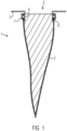
- Figure 1 shows a cross-section through an exemplary vacuum cleaner filter bag 1 with a bag wall 2 and a holding plate 3.
- the holding plate 3 in particular its flat connecting plate, serves to fix the vacuum cleaner filter bag 1 in a corresponding holder in a housing of a vacuum cleaner.
- the bag wall is not connected directly to the flat part of the holding plate 3, i.e. the connecting plate, as is usual in the prior art, but to a nozzle 4 of the holding plate 3 which is cylindrical at least in sections.
- the nozzle extends in the direction of the through-opening 5 formed in the holding plate 3, i.e. perpendicular to the plane in which the connecting plate lies.
- the bag wall 2 is connected along the circumference of the nozzle 4 to its outer surface, which also extends in the direction perpendicular to the connecting plate.
- Figure 2 shows a perspective view of an exemplary holding plate with a nozzle 4 that is at least partially cylindrical.
- the nozzle 4 comprises a cylindrical section.
- the shape of the cylindrical section can be freely selected and is not limited to the shape of a circular cylinder.
- the axis of the cylindrical section defines the longitudinal axis of the nozzle 4.
- the through-opening of the holding plate is provided along this longitudinal axis of the cylindrical section. This forms an inflow opening for the suction material into the filter bag, as in Figure 1 to see.
- the exemplary retaining plate 3 of the Figure 2 comprises a second section 8 adjacent to the cylindrical section with an enlarged circumference.
- the second section 8 projects radially outwards beyond the lateral surface of the cylindrical section.
- This second section 8 can correspond to the connecting plate, as in Figure 1 shown.
- the bag wall 2 is in the embodiment of the Figure 1 welded to the outer surface of the cylindrical section of the nozzle 4.
- the ultrasonic weld seams 6 can be seen.
- a clamping ring 7 is shown, which clamps the bag wall 2 to the outer surface of the cylindrical section of the nozzle 4.
- Such a clamping ring 7 can also establish the connection of the bag wall to the outer surface on its own.
- a sealing lip can also be provided on the through opening 5.
- Figure 3 shows a plan view of an exemplary tubular bag open on one side, as used in the manufacture of a vacuum cleaner filter bag according to Figure 1
- the bag wall 2 of the exemplary bag of the Figure 3 comprises two longitudinal welds 12, 13 and one transverse weld 14.
- the bag is open, i.e. without a weld, in order to connect it with a nozzle as in Figure 2 to enable this to be demonstrated by way of example.
- the transverse weld seam 14 could also be concavely or convexly curved to make better use of the installation space.
- a base in the form of a block base or a side fold would also be conceivable in the area of the transverse weld seam 14.
- the bag wall 2 comprises Figure 3 several surface folds 16 which run along the longitudinal weld seams 12, 13. At the open end 15, the folds are fixed in their position by a fixing device 17.
- fold in the sense of the present invention is defined as a sequence of two or more folds, wherein a single fold in the sense of the present invention is defined by two fold legs and a fold hinge.
- a fold hinge is the point of a fold with the smallest radius of curvature.
- the imaginary connection of the fold hinges creates a so-called fold axis.
- the fold axis is also called the fold back.
- the fold axis can correspond to the longitudinal axis of a fold. Areas of a fold with a radius of curvature that is larger than the minimum radius of curvature of the fold are called fold legs. The area between the fold legs of a fold is called the fold core.
- the fold legs of a fold can therefore also have a curvature.
- Folds can also have turning points. Turning points are those points on a fold, especially the fold legs, where the curvature of the fold changes from concave to convex.
- a connecting line that connects several turning points of a fold is called an inflexion line.
- Two adjacent folds can also share a fold leg. If several folds are planned in this way, a fold package or a fold train can be created.
- Folds can also have legs that run parallel to the bag wall. Such legs can be located between folds that protrude from the bag wall plane and thus have an opening on the upstream side in relation to the bag wall.
- the width of the parallel leg can be less than, preferably less than half or most preferably less than a quarter of the width of the opening of the fold protruding from the bag wall.
- the fold legs of the folds can be particularly smooth. "Smooth" means that the fold legs do not have any compaction and/or structuring, particularly that which is intended to stabilize the shape of the folds.
- One or more fold legs of one or more folds can comprise one or more embossed structures, in particular where the embossed structures do not serve to stabilize the shape of the folds. This can further increase the area available for filtration.
- the bag wall 2 can in particular have more than 5, 10, 20, 30, 40 or 50 folds, in particular also folds of these folds.
- the folds of the bag wall can have a substantially regular distance from one another. In other words, the distance between the fold backs of any two adjacent folds can be substantially constant.
- Folds can be horizontal or vertical.
- Horizontal folds are folds whose fold legs are arranged essentially parallel to the bag wall 2.
- Vertical folds are folds whose fold legs form an angle with the bag wall 2 of greater than 0° and less than 180°, in particular greater than 20° or greater than 45°.
- a standing fold is also understood to mean a fold in which a plane in which both the fold axis and the turning line of the fold lie, with a flat, horizontal surface on which the first and/or second bag wall is arranged, encloses an angle greater than 45°, in particular greater than 30°, in particular greater than 10°.
- a lying fold can be understood to mean a fold in which the plane encloses an angle of less than 45°, in particular less than 30°, in particular less than 10°, with this surface.
- the vacuum cleaner filter bag in particular the folded nonwoven material, is placed on a flat, horizontal surface.
- the vacuum cleaner filter bag can also be cut open and, in particular, placed on the surface in such a way that the inflow side or inside of the original vacuum cleaner filter bag rests on the surface.
- Lying folds can be mutually overlapping, non-overlapping and/or partially overlapping.
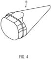
- FIG. 1 To produce an example vacuum cleaner filter bag as shown in Figure 1 As shown, it is necessary to connect the bag wall 2 to the nozzle 4. Although the nozzle 4 made of plastic has a certain strength, in the case of a connection by welding it is advantageous if an anvil is provided which forms an abutment. Figure 4 shows such an anvil in the form of a conical guide element 18.
- the conical guide element 18 can be arranged vertically on a work table.
- the conical guide element 18 is designed such that its outer diameter at the wide end corresponds to the inner diameter of the cylindrical section of the nozzle 4.
- the holding plate 3 with nozzle 4 is then mounted as in Figure 5 shown over the conical guide element 18.
- a robot gripper can then pick up a tubular bag open on one side, such as in Figure 3 shown, and also put it over the conical guide element 18.
- the conical shape of the guide element 18 is advantageous.
- the bag wall 2 can be welded to the The welding can be carried out on the outer surface of the cylindrical section of the nozzle 4, from the outside.
- the latter has the advantage that the welding result can be checked, for example by means of image processing.
Landscapes
- Engineering & Computer Science (AREA)
- Mechanical Engineering (AREA)
- Filters For Electric Vacuum Cleaners (AREA)
Priority Applications (8)
| Application Number | Priority Date | Filing Date | Title |
|---|---|---|---|
| DK19208499.4T DK3821776T3 (da) | 2019-11-12 | 2019-11-12 | Støvsugerfilterpose til håndstøvsuger |
| PL19208499.4T PL3821776T3 (pl) | 2019-11-12 | 2019-11-12 | Worek filtrujący do odkurzacza ręcznego |
| ES19208499T ES3013504T3 (en) | 2019-11-12 | 2019-11-12 | Vacuum cleaner filter bag for a hand vacuum cleaner |
| EP19208499.4A EP3821776B1 (de) | 2019-11-12 | 2019-11-12 | Staubsaugerfilterbeutel für einen handstaubsauger |
| PCT/EP2020/080289 WO2021094089A1 (de) | 2019-11-12 | 2020-10-28 | Staubsaugerfilterbeutel für einen handstaubsauger |
| AU2020384249A AU2020384249A1 (en) | 2019-11-12 | 2020-10-28 | Vacuum-cleaner filter bag for a hand-held vacuum cleaner |
| US17/775,396 US20220386838A1 (en) | 2019-11-12 | 2020-10-28 | Vacuum-cleaner filter bag for a hand-held vacuum cleaner |
| CN202080077558.3A CN114901115A (zh) | 2019-11-12 | 2020-10-28 | 用于手持式吸尘器的吸尘器过滤袋 |
Applications Claiming Priority (1)
| Application Number | Priority Date | Filing Date | Title |
|---|---|---|---|
| EP19208499.4A EP3821776B1 (de) | 2019-11-12 | 2019-11-12 | Staubsaugerfilterbeutel für einen handstaubsauger |
Publications (2)
| Publication Number | Publication Date |
|---|---|
| EP3821776A1 EP3821776A1 (de) | 2021-05-19 |
| EP3821776B1 true EP3821776B1 (de) | 2025-01-01 |
Family
ID=68581202
Family Applications (1)
| Application Number | Title | Priority Date | Filing Date |
|---|---|---|---|
| EP19208499.4A Active EP3821776B1 (de) | 2019-11-12 | 2019-11-12 | Staubsaugerfilterbeutel für einen handstaubsauger |
Country Status (8)
| Country | Link |
|---|---|
| US (1) | US20220386838A1 (pl) |
| EP (1) | EP3821776B1 (pl) |
| CN (1) | CN114901115A (pl) |
| AU (1) | AU2020384249A1 (pl) |
| DK (1) | DK3821776T3 (pl) |
| ES (1) | ES3013504T3 (pl) |
| PL (1) | PL3821776T3 (pl) |
| WO (1) | WO2021094089A1 (pl) |
Families Citing this family (5)
| Publication number | Priority date | Publication date | Assignee | Title |
|---|---|---|---|---|
| DE102020100577B4 (de) | 2020-01-13 | 2021-09-23 | Branofilter Gmbh | Staubsaugerfilterbeuteleinrichtung |
| WO2023114206A1 (en) * | 2021-12-13 | 2023-06-22 | Valco Cincinnati, Inc. | Machine vision system for inspecting quality of various non-woven materials |
| EP4364625A1 (de) | 2022-11-07 | 2024-05-08 | Wolf PVG GmbH & Co. KG | Staubsaugerbeutel und verfahren zur herstellung eines staubsaugerbeutels |
| DE102023113313A1 (de) | 2023-05-22 | 2024-11-28 | Branofilter Gmbh | Staubfilterbeuteleinrichtung für einen Staubsauger |
| US20250098917A1 (en) * | 2023-09-25 | 2025-03-27 | Marco Polo Industries Co Ltd | Animal litter vacuum device |
Citations (9)
| Publication number | Priority date | Publication date | Assignee | Title |
|---|---|---|---|---|
| DE1934708U (de) * | 1965-11-16 | 1966-03-17 | Siemens Electrogeraet Ag | Filterbeutel fuer handstaubsauger. |
| US3457707A (en) | 1965-03-30 | 1969-07-29 | Studley Paper Co | Vacuum cleaner filter bag |
| DE2140894A1 (de) * | 1971-08-14 | 1973-03-01 | Vorwerk & Co Elektrowerke Kg | Staubsauger-filterbeutel |
| EP0100438A2 (de) * | 1982-07-30 | 1984-02-15 | Euras Elektro Forschungs- und Produktionsgesellschaft mbH | Batteriebetriebener, über einen Ladesockel wiederaufladbarer Handstaubsauger |
| US20050081321A1 (en) * | 2003-10-15 | 2005-04-21 | Milligan Michael A. | Hand-held cordless vacuum cleaner |
| CN100536745C (zh) | 2007-03-12 | 2009-09-09 | 泰怡凯电器(苏州)有限公司 | 用于真空吸尘器的集尘室 |
| SE536624C2 (sv) * | 2012-01-16 | 2014-04-08 | Konstruktion & Design J R Liland | Förfarande för anpassning av en dammsugarpåse till en dammsugare |
| EP2772173A1 (de) * | 2013-02-28 | 2014-09-03 | Wolf PVG GmbH & Co. KG | Filterbeutel für einen Staubsauger und Verfahren zur Herstellung einer Halteplatte für einen Filterbeutel |
| US20170296014A1 (en) * | 2016-04-15 | 2017-10-19 | Tti (Macao Commercial Offshore) Limited | Vacuum cleaner and filter for a vacuum cleaner |
Family Cites Families (22)
| Publication number | Priority date | Publication date | Assignee | Title |
|---|---|---|---|---|
| DE1943708U (de) | 1965-01-21 | 1966-08-04 | Heinz Buschjost | Magnetventil mit kugel als differentialkolben. |
| US4211543A (en) * | 1978-04-24 | 1980-07-08 | Donaldson Company, Inc. | Air cleaner with replaceable filter element |
| US4304579A (en) * | 1980-09-29 | 1981-12-08 | Celeste Industries Corporation | Extended area bag filter |
| DE8703012U1 (de) * | 1987-02-27 | 1987-04-09 | Branofilter Gmbh, 8501 Dietenhofen | In ein staubabsaugendes Gerät einzusetzende Vorrichtung zur Aufnahme des abgesaugten Staubes |
| DE9403072U1 (de) * | 1994-02-24 | 1994-04-21 | Branofilter GmbH, 90599 Dietenhofen | Staubfiltersack |
| SE9604267L (sv) * | 1996-11-21 | 1998-05-11 | Anders Rydin | Dammavskiljare för en dammsugare |
| DE19738178C2 (de) * | 1997-09-02 | 1999-12-02 | Freudenberg Carl Fa | Filterpatrone und Verfahren zu ihrer Herstellung |
| WO2007059937A1 (de) * | 2005-11-22 | 2007-05-31 | Eurofilters Holding N.V. | Stutzen mit ablenkvorrichtung für einen staubsauger |
| DE202006016789U1 (de) * | 2006-11-03 | 2006-12-28 | Branofilter Gmbh | Anschlussstück für einen Staubfilterbeutel sowie mit einem solchen Anschlussstück ausgestatteter Staubfilterbeutel |
| ES2440722T3 (es) * | 2008-03-07 | 2014-01-30 | Eurofilters Holding N.V. | Bolsa de filtro de aspiradora |
| DE202008018054U1 (de) * | 2008-08-29 | 2011-04-28 | Vorwerk & Co. Interholding Gmbh | Filterbeutel für einen Staubsauger |
| DE102008062601A1 (de) * | 2008-12-17 | 2010-06-24 | Vorwerk & Co. Interholding Gmbh | Verfahren zum Betreiben eines Staubsaugers sowie elektromotorisch betriebener Staubsauger und schlauchförmiger Filtermaterialvorrat |
| DK2311360T3 (da) | 2009-10-19 | 2014-10-06 | Eurofilters Holding Nv | Støvsugerfilterpose |
| ES2560672T3 (es) * | 2009-10-19 | 2016-02-22 | Eurofilters Holding N.V. | Placa de sujeción para una bolsa filtrante de aspiradora |
| ES2508291T3 (es) | 2010-03-19 | 2014-10-16 | Eurofilters Holding N.V. | Bolsa de filtro de aspiradora |
| CN204380423U (zh) * | 2015-01-12 | 2015-06-10 | 四川省有色冶金研究院有限公司 | 一种结构优化的脉冲袋式除尘器用过滤设施 |
| DE102015104896A1 (de) * | 2015-03-30 | 2016-10-06 | Vorwerk & Co. Interholding Gmbh | Filter für einen Staubsauger |
| US10092870B2 (en) * | 2015-05-22 | 2018-10-09 | Trane International Inc. | Filter assembly |
| ES2916748T3 (es) * | 2015-12-12 | 2022-07-05 | Procedimiento para producir una unión por material entre una placa de retención y la pared de una bolsa de filtro de aspiradora, así como bolsa de filtro de aspiradora | |
| EP3354178B1 (de) * | 2017-01-31 | 2021-11-17 | Eurofilters Holding N.V. | Bodenstaubsauger |
| DE102018100371A1 (de) * | 2018-01-09 | 2019-07-11 | Vorwerk & Co. Interholding Gmbh | Saugreinigungsgerät mit einem Filterbeutel sowie Filterbeutel für ein Saugreinigungsgerät |
| PL3821777T3 (pl) | 2019-11-12 | 2025-04-14 | Eurofilters Holding N.V. | Worek filtrujący do odkurzacza ręcznego |
-
2019
- 2019-11-12 DK DK19208499.4T patent/DK3821776T3/da active
- 2019-11-12 ES ES19208499T patent/ES3013504T3/es active Active
- 2019-11-12 PL PL19208499.4T patent/PL3821776T3/pl unknown
- 2019-11-12 EP EP19208499.4A patent/EP3821776B1/de active Active
-
2020
- 2020-10-28 CN CN202080077558.3A patent/CN114901115A/zh active Pending
- 2020-10-28 AU AU2020384249A patent/AU2020384249A1/en not_active Abandoned
- 2020-10-28 WO PCT/EP2020/080289 patent/WO2021094089A1/de not_active Ceased
- 2020-10-28 US US17/775,396 patent/US20220386838A1/en not_active Abandoned
Patent Citations (9)
| Publication number | Priority date | Publication date | Assignee | Title |
|---|---|---|---|---|
| US3457707A (en) | 1965-03-30 | 1969-07-29 | Studley Paper Co | Vacuum cleaner filter bag |
| DE1934708U (de) * | 1965-11-16 | 1966-03-17 | Siemens Electrogeraet Ag | Filterbeutel fuer handstaubsauger. |
| DE2140894A1 (de) * | 1971-08-14 | 1973-03-01 | Vorwerk & Co Elektrowerke Kg | Staubsauger-filterbeutel |
| EP0100438A2 (de) * | 1982-07-30 | 1984-02-15 | Euras Elektro Forschungs- und Produktionsgesellschaft mbH | Batteriebetriebener, über einen Ladesockel wiederaufladbarer Handstaubsauger |
| US20050081321A1 (en) * | 2003-10-15 | 2005-04-21 | Milligan Michael A. | Hand-held cordless vacuum cleaner |
| CN100536745C (zh) | 2007-03-12 | 2009-09-09 | 泰怡凯电器(苏州)有限公司 | 用于真空吸尘器的集尘室 |
| SE536624C2 (sv) * | 2012-01-16 | 2014-04-08 | Konstruktion & Design J R Liland | Förfarande för anpassning av en dammsugarpåse till en dammsugare |
| EP2772173A1 (de) * | 2013-02-28 | 2014-09-03 | Wolf PVG GmbH & Co. KG | Filterbeutel für einen Staubsauger und Verfahren zur Herstellung einer Halteplatte für einen Filterbeutel |
| US20170296014A1 (en) * | 2016-04-15 | 2017-10-19 | Tti (Macao Commercial Offshore) Limited | Vacuum cleaner and filter for a vacuum cleaner |
Non-Patent Citations (8)
| Title |
|---|
| ANONYMOUS: "Eurostar Backpack Vacuum Cleaner", FACEBOOK - HPA GROUP - HYGIENE PRODUCTS AUSTRALIA, 22 November 2014 (2014-11-22), pages 1 - 1, XP093324599, Retrieved from the Internet <URL:https://www.facebook.com/profile/100063645097082/search/?q=eurostar%20backpack> |
| D1 - "ERAC-Registrierung", 17 December 2013 (2013-12-17), [retrieved on 20231217] https://device.report/erac/SAA132509EA |
| D2 - Messestand der Firma MyPicture |
| D3 - Wesentlicher Ausschnitt des Messefotos |
| D5 - Kontaktaufnahme – Mailwechsel mit TÜV |
| D6a - Originalkarton des Fiorentini-Saugers mit der Seriennummer 2015050443 |
| D6b - Bilder des Fiorentini-Saugers mit der Seriennummer 2015050443 von allen Seiten |
| MONTECELIO GUIDONIA, PONTECORVO BRUNO: "Fiorentini-Katalog b2015", FIORENTINI-KATALO, FIORENTINI, 4 October 2021 (2021-10-04), pages 1 - 2, XP093324603, Retrieved from the Internet <URL:https://www.fiorentinispa.com/files/fotoSchede/download/63_1_b2015.pdf> |
Also Published As
| Publication number | Publication date |
|---|---|
| PL3821776T3 (pl) | 2025-03-17 |
| AU2020384249A1 (en) | 2022-06-02 |
| DK3821776T3 (da) | 2025-02-03 |
| US20220386838A1 (en) | 2022-12-08 |
| ES3013504T3 (en) | 2025-04-14 |
| EP3821776A1 (de) | 2021-05-19 |
| WO2021094089A1 (de) | 2021-05-20 |
| CN114901115A (zh) | 2022-08-12 |
Similar Documents
| Publication | Publication Date | Title |
|---|---|---|
| EP3821776B1 (de) | Staubsaugerfilterbeutel für einen handstaubsauger | |
| EP3821777B1 (de) | Staubsaugerfilterbeutel für einen handstaubsauger | |
| EP3219375B2 (de) | Staubsaugerfilterbeutel mit staub- und/oder faserförmigem recyclierten material | |
| EP3669735B1 (de) | Staubsaugerfilterbeutel mit verbesserter schweissnahtfestigkeit | |
| EP3219373B1 (de) | Staubsaugerfilterbeutel mit recyclierten textilmaterialien und/oder baumwolllinters | |
| EP3429723B1 (de) | Staubsaugerfilterbeutel mit recyclierten textilmaterialien und/oder baumwolllinters | |
| EP3219374A1 (de) | Staubsaugerfilterbeutel aus recyclierten kunststoffen | |
| EP3753463B1 (de) | Staubsaugerfilterbeutel für einen handstaubsauger | |
| EP3838095B1 (de) | Halteplatte für einen staubsaugerfilterbeutel |
Legal Events
| Date | Code | Title | Description |
|---|---|---|---|
| PUAI | Public reference made under article 153(3) epc to a published international application that has entered the european phase |
Free format text: ORIGINAL CODE: 0009012 |
|
| STAA | Information on the status of an ep patent application or granted ep patent |
Free format text: STATUS: THE APPLICATION HAS BEEN PUBLISHED |
|
| AK | Designated contracting states |
Kind code of ref document: A1 Designated state(s): AL AT BE BG CH CY CZ DE DK EE ES FI FR GB GR HR HU IE IS IT LI LT LU LV MC MK MT NL NO PL PT RO RS SE SI SK SM TR |
|
| STAA | Information on the status of an ep patent application or granted ep patent |
Free format text: STATUS: REQUEST FOR EXAMINATION WAS MADE |
|
| 17P | Request for examination filed |
Effective date: 20211118 |
|
| RBV | Designated contracting states (corrected) |
Designated state(s): AL AT BE BG CH CY CZ DE DK EE ES FI FR GB GR HR HU IE IS IT LI LT LU LV MC MK MT NL NO PL PT RO RS SE SI SK SM TR |
|
| TPAC | Observations filed by third parties |
Free format text: ORIGINAL CODE: EPIDOSNTIPA |
|
| TPAC | Observations filed by third parties |
Free format text: ORIGINAL CODE: EPIDOSNTIPA |
|
| STAA | Information on the status of an ep patent application or granted ep patent |
Free format text: STATUS: EXAMINATION IS IN PROGRESS |
|
| 17Q | First examination report despatched |
Effective date: 20221216 |
|
| TPAC | Observations filed by third parties |
Free format text: ORIGINAL CODE: EPIDOSNTIPA |
|
| GRAP | Despatch of communication of intention to grant a patent |
Free format text: ORIGINAL CODE: EPIDOSNIGR1 |
|
| STAA | Information on the status of an ep patent application or granted ep patent |
Free format text: STATUS: GRANT OF PATENT IS INTENDED |
|
| INTG | Intention to grant announced |
Effective date: 20240809 |
|
| GRAS | Grant fee paid |
Free format text: ORIGINAL CODE: EPIDOSNIGR3 |
|
| P01 | Opt-out of the competence of the unified patent court (upc) registered |
Free format text: CASE NUMBER: APP_54687/2024 Effective date: 20241004 |
|
| GRAA | (expected) grant |
Free format text: ORIGINAL CODE: 0009210 |
|
| STAA | Information on the status of an ep patent application or granted ep patent |
Free format text: STATUS: THE PATENT HAS BEEN GRANTED |
|
| AK | Designated contracting states |
Kind code of ref document: B1 Designated state(s): AL AT BE BG CH CY CZ DE DK EE ES FI FR GB GR HR HU IE IS IT LI LT LU LV MC MK MT NL NO PL PT RO RS SE SI SK SM TR |
|
| REG | Reference to a national code |
Ref country code: GB Ref legal event code: FG4D Free format text: NOT ENGLISH |
|
| REG | Reference to a national code |
Ref country code: DE Ref legal event code: R096 Ref document number: 502019012725 Country of ref document: DE |
|
| REG | Reference to a national code |
Ref country code: CH Ref legal event code: EP |
|
| REG | Reference to a national code |
Ref country code: NL Ref legal event code: FP |
|
| REG | Reference to a national code |
Ref country code: IE Ref legal event code: FG4D Free format text: LANGUAGE OF EP DOCUMENT: GERMAN |
|
| REG | Reference to a national code |
Ref country code: DK Ref legal event code: T3 Effective date: 20250129 |
|
| REG | Reference to a national code |
Ref country code: SE Ref legal event code: TRGR |
|
| REG | Reference to a national code |
Ref country code: ES Ref legal event code: FG2A Ref document number: 3013504 Country of ref document: ES Kind code of ref document: T3 Effective date: 20250414 |
|
| REG | Reference to a national code |
Ref country code: LT Ref legal event code: MG9D |
|
| PG25 | Lapsed in a contracting state [announced via postgrant information from national office to epo] |
Ref country code: FI Free format text: LAPSE BECAUSE OF FAILURE TO SUBMIT A TRANSLATION OF THE DESCRIPTION OR TO PAY THE FEE WITHIN THE PRESCRIBED TIME-LIMIT Effective date: 20250101 |
|
| PG25 | Lapsed in a contracting state [announced via postgrant information from national office to epo] |
Ref country code: IS Free format text: LAPSE BECAUSE OF FAILURE TO SUBMIT A TRANSLATION OF THE DESCRIPTION OR TO PAY THE FEE WITHIN THE PRESCRIBED TIME-LIMIT Effective date: 20250501 Ref country code: NO Free format text: LAPSE BECAUSE OF FAILURE TO SUBMIT A TRANSLATION OF THE DESCRIPTION OR TO PAY THE FEE WITHIN THE PRESCRIBED TIME-LIMIT Effective date: 20250401 |
|
| PG25 | Lapsed in a contracting state [announced via postgrant information from national office to epo] |
Ref country code: HR Free format text: LAPSE BECAUSE OF FAILURE TO SUBMIT A TRANSLATION OF THE DESCRIPTION OR TO PAY THE FEE WITHIN THE PRESCRIBED TIME-LIMIT Effective date: 20250101 |
|
| PG25 | Lapsed in a contracting state [announced via postgrant information from national office to epo] |
Ref country code: PT Free format text: LAPSE BECAUSE OF FAILURE TO SUBMIT A TRANSLATION OF THE DESCRIPTION OR TO PAY THE FEE WITHIN THE PRESCRIBED TIME-LIMIT Effective date: 20250502 Ref country code: LV Free format text: LAPSE BECAUSE OF FAILURE TO SUBMIT A TRANSLATION OF THE DESCRIPTION OR TO PAY THE FEE WITHIN THE PRESCRIBED TIME-LIMIT Effective date: 20250101 |
|
| PG25 | Lapsed in a contracting state [announced via postgrant information from national office to epo] |
Ref country code: GR Free format text: LAPSE BECAUSE OF FAILURE TO SUBMIT A TRANSLATION OF THE DESCRIPTION OR TO PAY THE FEE WITHIN THE PRESCRIBED TIME-LIMIT Effective date: 20250402 Ref country code: BG Free format text: LAPSE BECAUSE OF FAILURE TO SUBMIT A TRANSLATION OF THE DESCRIPTION OR TO PAY THE FEE WITHIN THE PRESCRIBED TIME-LIMIT Effective date: 20250101 |
|
| PG25 | Lapsed in a contracting state [announced via postgrant information from national office to epo] |
Ref country code: CZ Free format text: LAPSE BECAUSE OF FAILURE TO SUBMIT A TRANSLATION OF THE DESCRIPTION OR TO PAY THE FEE WITHIN THE PRESCRIBED TIME-LIMIT Effective date: 20250101 |
|
| REG | Reference to a national code |
Ref country code: DE Ref legal event code: R026 Ref document number: 502019012725 Country of ref document: DE |
|
| PLAN | Information deleted related to communication of a notice of opposition and request to file observations + time limit |
Free format text: ORIGINAL CODE: EPIDOSDOBS2 |
|
| PLAX | Notice of opposition and request to file observation + time limit sent |
Free format text: ORIGINAL CODE: EPIDOSNOBS2 |
|
| PG25 | Lapsed in a contracting state [announced via postgrant information from national office to epo] |
Ref country code: SM Free format text: LAPSE BECAUSE OF FAILURE TO SUBMIT A TRANSLATION OF THE DESCRIPTION OR TO PAY THE FEE WITHIN THE PRESCRIBED TIME-LIMIT Effective date: 20250101 |
|
| PLBI | Opposition filed |
Free format text: ORIGINAL CODE: 0009260 |
|
| PLAX | Notice of opposition and request to file observation + time limit sent |
Free format text: ORIGINAL CODE: EPIDOSNOBS2 |
|
| PG25 | Lapsed in a contracting state [announced via postgrant information from national office to epo] |
Ref country code: EE Free format text: LAPSE BECAUSE OF FAILURE TO SUBMIT A TRANSLATION OF THE DESCRIPTION OR TO PAY THE FEE WITHIN THE PRESCRIBED TIME-LIMIT Effective date: 20250101 |
|
| PG25 | Lapsed in a contracting state [announced via postgrant information from national office to epo] |
Ref country code: RO Free format text: LAPSE BECAUSE OF FAILURE TO SUBMIT A TRANSLATION OF THE DESCRIPTION OR TO PAY THE FEE WITHIN THE PRESCRIBED TIME-LIMIT Effective date: 20250101 |
|
| PG25 | Lapsed in a contracting state [announced via postgrant information from national office to epo] |
Ref country code: SK Free format text: LAPSE BECAUSE OF FAILURE TO SUBMIT A TRANSLATION OF THE DESCRIPTION OR TO PAY THE FEE WITHIN THE PRESCRIBED TIME-LIMIT Effective date: 20250101 |
|
| 26 | Opposition filed |
Opponent name: BRANOFILTER GMBH Effective date: 20250930 |
|
| PGFP | Annual fee paid to national office [announced via postgrant information from national office to epo] |
Ref country code: NL Payment date: 20251127 Year of fee payment: 7 |
|
| PGFP | Annual fee paid to national office [announced via postgrant information from national office to epo] |
Ref country code: DE Payment date: 20251128 Year of fee payment: 7 |
|
| PGFP | Annual fee paid to national office [announced via postgrant information from national office to epo] |
Ref country code: GB Payment date: 20251125 Year of fee payment: 7 |
|
| PGFP | Annual fee paid to national office [announced via postgrant information from national office to epo] |
Ref country code: IT Payment date: 20251127 Year of fee payment: 7 Ref country code: DK Payment date: 20251126 Year of fee payment: 7 |
|
| PGFP | Annual fee paid to national office [announced via postgrant information from national office to epo] |
Ref country code: FR Payment date: 20251128 Year of fee payment: 7 |
|
| PGFP | Annual fee paid to national office [announced via postgrant information from national office to epo] |
Ref country code: BE Payment date: 20251125 Year of fee payment: 7 |
|
| PGFP | Annual fee paid to national office [announced via postgrant information from national office to epo] |
Ref country code: SE Payment date: 20251127 Year of fee payment: 7 |
|
| PGFP | Annual fee paid to national office [announced via postgrant information from national office to epo] |
Ref country code: PL Payment date: 20251103 Year of fee payment: 7 |
|
| PGFP | Annual fee paid to national office [announced via postgrant information from national office to epo] |
Ref country code: ES Payment date: 20251201 Year of fee payment: 7 |
|
| PLBB | Reply of patent proprietor to notice(s) of opposition received |
Free format text: ORIGINAL CODE: EPIDOSNOBS3 |