EP3822045B1 - Manipulatorsteuervorrichtung, manipulatorsteuerverfahren und manipulatorsteuerprogramm - Google Patents
Manipulatorsteuervorrichtung, manipulatorsteuerverfahren und manipulatorsteuerprogramm Download PDFInfo
- Publication number
- EP3822045B1 EP3822045B1 EP19833125.8A EP19833125A EP3822045B1 EP 3822045 B1 EP3822045 B1 EP 3822045B1 EP 19833125 A EP19833125 A EP 19833125A EP 3822045 B1 EP3822045 B1 EP 3822045B1
- Authority
- EP
- European Patent Office
- Prior art keywords
- tilt angle
- manipulator
- obstacle
- target position
- robot
- Prior art date
- Legal status (The legal status is an assumption and is not a legal conclusion. Google has not performed a legal analysis and makes no representation as to the accuracy of the status listed.)
- Active
Links
Images

Classifications
-
- B—PERFORMING OPERATIONS; TRANSPORTING
- B25—HAND TOOLS; PORTABLE POWER-DRIVEN TOOLS; MANIPULATORS
- B25J—MANIPULATORS; CHAMBERS PROVIDED WITH MANIPULATION DEVICES
- B25J5/00—Manipulators mounted on wheels or on carriages
- B25J5/007—Manipulators mounted on wheels or on carriages mounted on wheels
-
- B—PERFORMING OPERATIONS; TRANSPORTING
- B25—HAND TOOLS; PORTABLE POWER-DRIVEN TOOLS; MANIPULATORS
- B25J—MANIPULATORS; CHAMBERS PROVIDED WITH MANIPULATION DEVICES
- B25J13/00—Controls for manipulators
- B25J13/08—Controls for manipulators by means of sensing devices, e.g. viewing or touching devices
- B25J13/088—Controls for manipulators by means of sensing devices, e.g. viewing or touching devices with position, velocity or acceleration sensors
- B25J13/089—Determining the position of the robot with reference to its environment
-
- B—PERFORMING OPERATIONS; TRANSPORTING
- B25—HAND TOOLS; PORTABLE POWER-DRIVEN TOOLS; MANIPULATORS
- B25J—MANIPULATORS; CHAMBERS PROVIDED WITH MANIPULATION DEVICES
- B25J9/00—Program-controlled manipulators
- B25J9/16—Program controls
- B25J9/1656—Program controls characterised by programming, planning systems for manipulators
- B25J9/1664—Program controls characterised by programming, planning systems for manipulators characterised by motion, path, trajectory planning
-
- B—PERFORMING OPERATIONS; TRANSPORTING
- B25—HAND TOOLS; PORTABLE POWER-DRIVEN TOOLS; MANIPULATORS
- B25J—MANIPULATORS; CHAMBERS PROVIDED WITH MANIPULATION DEVICES
- B25J9/00—Program-controlled manipulators
- B25J9/16—Program controls
- B25J9/1674—Program controls characterised by safety, monitoring, diagnostic
-
- B—PERFORMING OPERATIONS; TRANSPORTING
- B25—HAND TOOLS; PORTABLE POWER-DRIVEN TOOLS; MANIPULATORS
- B25J—MANIPULATORS; CHAMBERS PROVIDED WITH MANIPULATION DEVICES
- B25J9/00—Program-controlled manipulators
- B25J9/16—Program controls
- B25J9/1674—Program controls characterised by safety, monitoring, diagnostic
- B25J9/1676—Avoiding collision or forbidden zones
-
- B—PERFORMING OPERATIONS; TRANSPORTING
- B25—HAND TOOLS; PORTABLE POWER-DRIVEN TOOLS; MANIPULATORS
- B25J—MANIPULATORS; CHAMBERS PROVIDED WITH MANIPULATION DEVICES
- B25J9/00—Program-controlled manipulators
- B25J9/16—Program controls
- B25J9/1694—Program controls characterised by use of sensors other than normal servo-feedback from position, speed or acceleration sensors, perception control, multi-sensor controlled systems, sensor fusion
- B25J9/1697—Vision controlled systems
-
- G—PHYSICS
- G05—CONTROLLING; REGULATING
- G05D—SYSTEMS FOR CONTROLLING OR REGULATING NON-ELECTRIC VARIABLES
- G05D1/00—Control of position, course, altitude or attitude of land, water, air or space vehicles, e.g. using automatic pilots
- G05D1/02—Control of position or course in two dimensions
- G05D1/021—Control of position or course in two dimensions specially adapted to land vehicles
- G05D1/0231—Control of position or course in two dimensions specially adapted to land vehicles using optical position detecting means
- G05D1/0246—Control of position or course in two dimensions specially adapted to land vehicles using optical position detecting means using a video camera in combination with image processing means
-
- G—PHYSICS
- G05—CONTROLLING; REGULATING
- G05D—SYSTEMS FOR CONTROLLING OR REGULATING NON-ELECTRIC VARIABLES
- G05D1/00—Control of position, course, altitude or attitude of land, water, air or space vehicles, e.g. using automatic pilots
- G05D1/08—Control of attitude, i.e. control of roll, pitch, or yaw
- G05D1/0891—Control of attitude, i.e. control of roll, pitch, or yaw specially adapted for land vehicles
-
- B—PERFORMING OPERATIONS; TRANSPORTING
- B25—HAND TOOLS; PORTABLE POWER-DRIVEN TOOLS; MANIPULATORS
- B25J—MANIPULATORS; CHAMBERS PROVIDED WITH MANIPULATION DEVICES
- B25J9/00—Program-controlled manipulators
- B25J9/16—Program controls
- B25J9/1615—Program controls characterised by special kind of manipulator, e.g. planar, scara, gantry, cantilever, space, closed chain, passive/active joints and tendon driven manipulators
- B25J9/162—Mobile manipulator, movable base with manipulator arm mounted on it
-
- G—PHYSICS
- G05—CONTROLLING; REGULATING
- G05B—CONTROL OR REGULATING SYSTEMS IN GENERAL; FUNCTIONAL ELEMENTS OF SUCH SYSTEMS; MONITORING OR TESTING ARRANGEMENTS FOR SUCH SYSTEMS OR ELEMENTS
- G05B2219/00—Program-control systems
- G05B2219/30—Nc systems
- G05B2219/37—Measurements
- G05B2219/37376—Inclination, gradient of machine base
-
- G—PHYSICS
- G05—CONTROLLING; REGULATING
- G05B—CONTROL OR REGULATING SYSTEMS IN GENERAL; FUNCTIONAL ELEMENTS OF SUCH SYSTEMS; MONITORING OR TESTING ARRANGEMENTS FOR SUCH SYSTEMS OR ELEMENTS
- G05B2219/00—Program-control systems
- G05B2219/30—Nc systems
- G05B2219/39—Robotics, robotics to robotics hand
- G05B2219/39182—Compensation for base, floor deformation
Definitions
- the present invention relates to a manipulator controller, a manipulator control method, and a manipulator control program.
- the movable manipulator may include a movable robot and a manipulator installed on the robot.
- the movable robot When the movable robot is on a sloping floor or has run on a low step, the movable manipulator may tilt.
- the manipulator When the manipulator is moved to a target position without being controlled to reflect the tilt, the manipulator may reach a different target position due to the tilt, thus failing to perform a correct operation.
- an obstacle such as a display shelf
- the manipulator may perform erroneous operations such as colliding with the display shelf.
- a known technique measures the tilt angle of a movable robot that operates while measuring the surrounding environment using a two-dimensional (2D) laser range finder during operation, and uses the measured tilt angle of the movable robot to generate a map and to estimate the position and the posture of the movable robot (refer to, for example, JP 2018-5709 A ).
- Another known technique measures the tilt angle of a movable robot, and controls a base included in the movable robot to have a reduced tilt angle and horizontally place a gripper mounted on the base (refer to, for example, JP 2013-101593 A ).
- US 2015 / 113 820 A1 discloses an arm type three-dimensional measuring machine including: a multi-jointed arm mechanism comprising a probe in a distal end; a processing part for computing a position of said probe; and an inclinometer configured to detect an inclination amount of a base part from a vertical direction in the base part for supporting the multi-jointed arm mechanism, wherein the processing part computes a position of the probe using the base part as a criterion and corrects the position of the probe using the base part as the criterion in a time-series manner based on an output from the inclinometer.
- US 2016 / 059 411 A1 discloses an apparatus for manipulating articles in which a multiaxial industrial robot is arranged on a travel unit and the industrial robot and the travel unit can be supplied with electrical energy via an energy storage unit.
- the travel unit has a control unit and at least three wheels having at least one drive unit, wherein the control unit is configured to rotate at least one of the wheels by the drive unit about an axis of rotation standing perpendicular on a symmetrical axis of rotation of the wheel and to rotate it about the symmetrical axis of rotation by the respective drive unit so that the apparatus is travelable in any directions by the travel unit.
- area monitoring sensors are arranged at at least two sides of the travel unit.
- US 2015 / 035 969 A1 discloses a movement assistance robot including a robot arm unit that is disposed in a base traveling using drive wheels driven by a drive source, that includes multiple arms which are mutually and relatively movable by a drive unit, and that is configured to be transformable into multiple form types respectively coping with multiple movement postures (standing-upright walking assistance mode, hand support walking assistance mode, elbow support walking assistance mode, standing-upright riding movement mode, and seat riding movement mode) of a care receiver, a holding unit that is disposed in a distal end portion of the robot arm unit so as to support a care receiver, a selective operation unit that selects one form type from the multiple form types, and a transformation control unit that drives the drive unit and transforms the robot arm unit into a form type selected by the selective operation unit.
- a movement assistance robot including a robot arm unit that is disposed in a base traveling using drive wheels driven by a drive source, that includes multiple arms which are mutually and relatively movable by a drive unit, and that is configured to
- Patent Literature 1 uses the measured tilt angle of the movable robot to generate a map and estimate the position and the posture of a movable object rather than to correct the operation of a manipulator in accordance with the tilt angle. The technique is thus not easily applicable to a machine for picking and placing products.
- Patent Literature 2 uses a large and complex mechanism to maintain the base to be horizontal, and thus increases the size of the machine and the cost.
- one or more aspects of the present invention are directed to a manipulator controller, a manipulator control method, and a manipulator control program for reducing operational errors when a base receiving a manipulator tilts relative to a reference surface.
- a manipulator controller according to an aspect of the present invention comprises the features of claim 1.
- the control unit may output a notification in response to the tilt angle equal to or greater than a predetermined value.
- a manipulator control method is implementable by a computer.
- the method comprises the features of claim 3.
- a manipulator control program according to still another aspect of the present invention comprises the features of claim 4.
- the aspects of the present invention may reduce operational errors when a base receiving a manipulator tilts relative to a reference surface.
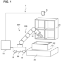
- Fig. 1 is a diagram of a pick and place machine 1 according to the present embodiment showing its configuration.
- the pick and place machine 1 includes a movable manipulator MP, an image sensor S, and a manipulator controller 10.
- the movable manipulator MP includes a movable unit M as an example base and a robot RB as an example manipulator installed on the movable unit M.
- the movable unit M includes four wheels R driven to rotate by a motor (not shown) and moves across a floor in response to instructions from the manipulator controller 10.
- the robot RB holds a workpiece (not shown) contained in a box 22 placed on a stand 20, transports the workpiece to a shelf 24, and then places the workpiece in the shelf 24.
- the robot RB includes a robot hand H attached to the distal end of its robot arm as an example end effector and holds a workpiece in the box 22 by gripping the workpiece with the robot hand H.
- the workpiece held is transported to the shelf 24 and then released to be placed in position.
- the member for holding a workpiece is not limited to the robot hand H and may be a suction pad for attracting a workpiece.
- the image sensor S is located above the box 22.
- the image sensor S captures a still image of a set of workpieces contained in the box 22.
- the manipulator controller 10 generates a path from any initial posture of the robot RB to a target posture.
- the path refers to a list of postures of the robot RB during an operation from the initial posture to the target posture. More specifically, the manipulator controller 10 processes a captured image obtained from the image sensor S and identifies the position and the posture of a workpiece to be held based on the result of the image processing. The manipulator controller 10 then generates first to third paths each including an initial posture and a target posture.
- the initial posture is a retracted posture in which the robot RB has retracted out of the view range of the image sensor S to allow the image sensor S to capture an image of workpieces in the box 22, and the target posture is a holding posture in which the robot RB has held a workpiece in the box 22.
- the initial posture is the holding posture in which the robot RB has held a workpiece in the box 22, and the target posture is a placing posture in which the robot RB has placed the workpiece in the shelf 24.
- the initial posture is the placing posture in which the robot RB has placed a workpiece in the shelf 24, and the target posture is the retracted posture in which the robot RB has retracted out of the view range of the image sensor S to allow the image sensor S to capture an image of workpieces in the box 22.
- an image sensor for capturing an image of the shelf 24 may be added and the image captured by the image sensor may be used to identify a position on which a workpiece is placed.
- the manipulator controller 10 then outputs an operational command value to the robot RB to operate the robot RB in accordance with the generated paths.
- the robot RB will now be described. Although a vertical articulated robot is used as an example of the robot RB in the present embodiment, the present embodiment may also use, for example, a horizontal articulated robot (selective compliance assembly robot arm, or SCARA, robot) and a parallel link robot.
- SCARA selective compliance assembly robot arm
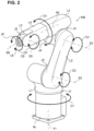
- Fig. 2 is a diagram of the robot RB as a vertical articulated robot, showing its structure.
- the robot RB is a six-axis robot with six degrees of freedom.
- the robot RB includes a base link BL, links L1 to L6, and joints J1 to J6. Each joint connects links together.
- the links L1 to L6 and the robot hand H connected to the link L6 are herein collectively referred to as a robot arm.
- the base link BL and the link L1 are connected to each other with the joint J1, which rotates in the direction indicated by arrow C1 about a vertical axis S1 in Fig. 2 .
- the link L1 pivots in the direction indicated by arrow C1 on the base link BL.
- the links L1 and L2 are connected to each other with the joint J2, which rotates in the direction indicated by arrow C2 about a horizontal axis S2 in Fig. 2 .
- the link L2 pivots in the direction indicated by arrow C2 on the link L1.
- the links L2 and L3 are connected to each other with the joint J3, which rotates in the direction indicated by arrow C3 about an axis S3 in Fig. 2 .
- the link L3 pivots in the direction indicated by arrow C3 on the link L2.
- the links L3 and L4 are connected to each other with the joint J4, which rotates in the direction indicated by arrow C4 about an axis S4 in Fig. 2 .
- the link L4 pivots in the direction indicated by arrow C4 on the link L3.
- the links L4 and L5 are connected to each other with the joint J5, which rotates in the direction indicated by arrow C5 about an axis S5 in Fig. 2 .
- the link L5 pivots in the direction indicated by arrow C5 on the link L4.
- the links L5 and L6 are connected to each other with the joint J6, which rotates in the direction indicated by arrow C6 about an axis S6 in Fig. 2 .
- the link L6 pivots in the direction indicated by arrow C6 on the link L5.
- the robot hand H attached to the link L6 is not shown in Fig. 2 .
- Each of the joints J1 to J6 has a predetermined rotational angle range as its movable range.
- the posture of the robot RB is determined by the combination of the rotational angles of the joints J1 to J6.
- the operational command value for operating the robot RB is equivalent to the rotational angle of each of the joints J1 to J6 corresponding to a target posture for the robot RB.
- Fig. 3 is a block diagram of the manipulator controller 10 according to the present embodiment showing its hardware configuration.
- the manipulator controller 10 includes a central processing unit (CPU) 11, a read-only memory (ROM) 12, a random-access memory (RAM) 13, a storage 14, an input unit 15, a monitor 16, an optical disc driver 17, and a communication interface 18.
- CPU central processing unit
- ROM read-only memory
- RAM random-access memory
- storage 14 an input unit 15, a monitor 16, an optical disc driver 17, and a communication interface 18.
- the components are connected to one another with a bus 19 in a communicable manner.
- the ROM 12 or the storage 14 stores a manipulator control program for performing a manipulator control process.
- the CPU 11 executes various programs and controls the components. More specifically, the CPU 11 reads a program from the ROM 12 or the storage 14 and executes the program using the RAM 13 as a work area. The CPU 11 controls the components and performs various arithmetic processes in accordance with the programs stored in the ROM 12 or the storage 14.
- the ROM 12 stores programs and data.
- the RAM 13 serves as a work area for temporarily storing programs or data.
- the storage 14 includes a hard disk drive (HDD) or a solid-state drive (SSD) and stores various programs including an operating system and stores various items of data.
- HDD hard disk drive
- SSD solid-state drive
- the input unit 15 includes a keyboard 151 and a pointing device such as a mouse 152, and is used for various input operations.
- the monitor 16 is, for example, a liquid crystal display, and displays various sets of information.
- the monitor 16 may include a touchscreen display that can also serve as the input unit 15.
- the optical disc driver 17 reads data stored in recording media, such as compact disc read-only memories (CD-ROMs) and Blu-ray discs, and writes data onto recording media.
- the communication interface 18 communicates with other components including the robot RB and the image sensor S, and uses a standard such as Ethernet (registered trademark), Fiber Distributed Data Interface (FDDI), Wi-Fi (registered trademark), a universal serial bus (USB), or IEEE 1394.
- Ethernet registered trademark
- FDDI Fiber Distributed Data Interface
- Wi-Fi registered trademark
- USB universal serial bus
- Fig. 4 is a functional block diagram of the manipulator controller 10.
- the manipulator controller 10 includes, as its functional components, a tilt angle obtainer 30, a target position obtainer 32, an obstacle information obtainer 34, a correction unit 36, a control unit 38, and a storage unit 40 as shown in Fig. 4 .
- Each functional component is implemented by the CPU 11 reading the manipulator control program stored in the ROM 12 or the storage 14, expanding the program into the RAM 13, and executing the program.
- the tilt angle obtainer 30 obtains the tilt angle of the movable unit M receiving the robot RB relative to a reference surface.
- the reference surface is, for example, a horizontal plane in the present embodiment.
- tilt sensors K1 and K2 are mounted on the same surface as the surface of the movable unit M on which the robot RB is installed.
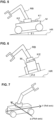
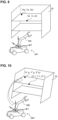
- the tilt sensor K1 detects a pitch tilt angle ⁇ 1 of the movable unit M receiving the robot RB relative to a horizontal plane HR.
- the pitch tilt angle ⁇ 1 is a tilt angle in the rotation direction about a pitch axis relative to a horizontal plane when the X axis is the pitch axis and the Y axis perpendicular to the X axis is a roll axis as shown in Fig. 7 .
- the tilt sensor K2 detects a roll tilt angle ⁇ 2 of the movable unit M receiving the robot RB relative to the horizontal plane HR.
- the roll tilt angle ⁇ 2 is a tilt angle in the rotation direction about a roll axis relative to a horizontal plane when the X axis is the pitch axis and the Y axis perpendicular to the X axis is the roll axis as shown in Fig. 7 .
- the tilt angle obtainer 30 obtains the pitch tilt angle ⁇ 1 from the tilt sensor K1 and the roll tilt angle ⁇ 2 from the tilt sensor K2.
- the target position obtainer 32 obtains a target position for the robot RB when the movable unit M has no tilt to the horizontal plane HR.
- the obstacle information obtainer 34 obtains obstacle information about the shape and the position of predefined obstacles.
- the correction unit 36 corrects the target position to a corrected target position in accordance with the pitch tilt angle ⁇ 1 and the roll tilt angle ⁇ 2 based on the pitch tilt angle ⁇ 1 and the roll tilt angle ⁇ 2 obtained by the tilt angle obtainer 30, the target position obtained by the target position obtainer 32, and the obstacle information obtained by the obstacle information obtainer 34.
- the control unit 38 controls the operation of the robot RB based on a corrected target posture determined by the correction unit 36 using the current position and the corrected target position for the robot RB.
- the storage unit 40 stores various sets of information including the manipulator control program and the obstacle information.
- the obstacle information is about the shape and the position of obstacles.
- the obstacles in the present embodiment include the stand 20, the box 22, and the shelf 24.
- the movable unit M is stationary in one place.
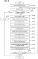
- Fig. 8 is a flowchart showing the manipulator control process performed by the CPU 11 in the manipulator controller 10.
- the CPU 11 reads the manipulator control program from the ROM 12 or the storage 14, expands the program into the RAM 13, and executes the program to perform the manipulator control process.
- the CPU 11, which functions as the tilt angle obtainer 30, obtains the pitch tilt angle ⁇ 1 from the tilt sensor K1 and the roll tilt angle ⁇ 2 from the tilt sensor K2 (step S102).
- the threshold is a predetermined value at and above which the movable manipulator MP may fall down.
- step S104 When at least either the pitch tilt angle ⁇ 1 or the roll tilt angle ⁇ 2 is equal to or greater than the predetermined threshold (Yes in step S104), or more specifically when the movable manipulator MP may fall down, the processing advances to step S105.
- step S105 the CPU 11, which functions as the control unit 38, notifies that the movable manipulator MP may fall down. More specifically, the CPU 11, for example, displays a warning message indicating that the movable manipulator MP may fall down on the monitor 16. In another embodiment, a buzzer (not shown) may be connected to the manipulator controller 10 and notify, by sound, that the movable manipulator MP may fall down. In another embodiment, a warning light (not shown) may be connected to the manipulator controller 10 and notify, by light, that the movable manipulator MP may fall down.
- step S106 When both the pitch tilt angle ⁇ 1 and the roll tilt angle ⁇ 2 are less than the predetermined threshold (No in step S104), or more specifically when the movable manipulator MP will not fall down, the processing advances to step S106.
- the CPU 11 which functions as the control unit 38, instructs the image sensor S to capture an image and then obtains the image captured by the image sensor S (step S106).
- the workpiece to be held may be, for example, a workpiece at the top in the set of workpieces, a workpiece in the center in the set of workpieces, a workpiece that does not overlap the other workpieces, or a workpiece that is selected based on other criteria.
- the corrected target position is calculated with the formula below, where the target position obtained in step S108 is (Xg, Yg, Zg) and the corrected target position is (X'g, Y'g, Z'g).
- R is the three-dimensional (3D) rotation matrix with the pitch tilt angle ⁇ 1 and the roll tilt angle ⁇ 2 as the parameters as shown below.
- Formula 2 R cos ⁇ 2 sin ⁇ 1 sin ⁇ 2 ⁇ cos ⁇ 1 sin ⁇ 2 0 cos ⁇ 1 sin ⁇ 1 sin ⁇ 2 ⁇ sin ⁇ 1 cos ⁇ 2 cos ⁇ 1 cos ⁇ 2
- the corrected obstacle position is calculated with the formula below, where the position of the box 22 as an obstacle obtained in step S100 is (Xt, Yt, Zt) and the corrected obstacle position is (X't, Y't, Z't).
- the first path may be generated using a known path planning technique. The same applies to the second and third paths described later.
- the placement position in the shelf 24 on which the robot RB places the workpiece may be obtained in the manner described below.
- a plurality of placement positions in the shelf 24 are taught in advance, and the storage unit 40 stores the position information indicating the plurality of taught placement positions and the order in which workpieces are to be placed on the plurality of placement positions.
- the robot RB then uses each placement position as a target position in the placement order.
- An image sensor for capturing an image of the shelf 24 may be added and the placement position on which a workpiece is placed may be selected using the captured image of the shelf 24, in the same manner as when a workpiece to be held is selected.
- the target position for the robot RB and the obstacle position are corrected and then used to control the operation of the robot RB in the present embodiment. This reduces operational errors when the movable unit M tilts relative to the horizontal plane.
- the target position for the robot RB is (Xg, Yg, Zg) and the reference point of the shelf 24 as an obstacle is the obstacle position (Xt, Yt, Zt).
- the target position is corrected by the processing in step S118 and the position of the shelf 24 as an obstacle is corrected by the processing in step S120 to maintain the relative relationship between the corrected target position (X'g, Y'g, Z'g) and the corrected obstacle position (X't, Y't, Z't) equal to the relative relationship between the target position (Xg, Yg, Zg) and the obstacle position (Xt, Yt, Zt) before the correction as shown in Fig. 10 .
- This reduces operational errors, such as collisions between the robot arm of the robot RB and the shelf 24 when the workpiece is to be placed in the shelf 24.
- the robot RB is installed on the movable unit M in the present embodiment, the present invention may apply to a robot RB that is installed on a stationary base.
- processors other than the CPU.
- processors include field-programmable gate arrays (FPGAs) and other programmable logic devices (PLDs) that are reconfigurable after being manufactured, and dedicated electric circuits with circuit configurations specially designed to perform specific processing, such as application-specific integrated circuits (ASICs).
- FPGAs field-programmable gate arrays
- PLDs programmable logic devices
- ASICs application-specific integrated circuits
- the path planning may be performed by one of such processors or a combination of two or more processors of the same type or different types (for example, a plurality of FPGAs or a combination of a CPU and an FPGA).
- the processors include, as their hardware components, electric circuits combining circuit elements such as semiconductor devices.
- the storage device is not limited to such examples.
- the program may be stored in a recording medium such as a compact disc read-only memory (CD-ROM), a digital versatile disc read-only memory (DVD-ROM), or a universal serial bus (USB) memory device.
- the program may be downloaded from an external device through a network.
Landscapes
- Engineering & Computer Science (AREA)
- Robotics (AREA)
- Mechanical Engineering (AREA)
- Physics & Mathematics (AREA)
- Aviation & Aerospace Engineering (AREA)
- Automation & Control Theory (AREA)
- General Physics & Mathematics (AREA)
- Remote Sensing (AREA)
- Radar, Positioning & Navigation (AREA)
- Human Computer Interaction (AREA)
- Health & Medical Sciences (AREA)
- Electromagnetism (AREA)
- Multimedia (AREA)
- Computer Vision & Pattern Recognition (AREA)
- Orthopedic Medicine & Surgery (AREA)
- General Health & Medical Sciences (AREA)
- Manipulator (AREA)
Claims (4)
- Manipulatorsteuerung (10), aufweisend:eine Neigungswinkelerlangungseinrichtung (30), die eingerichtet ist, einen Neigungswinkel einer Basis (M) relativ zu einer Referenzfläche zu erlangen, wobei die Basis (M) einen Manipulator (RB) aufnimmt;eine Zielpositionserlangungseinrichtung (32), die eingerichtet ist, eine Zielposition des Manipulators (RB) auf der Basis (M) in einem Zustand zu erlangen, in dem die Basis (M) relativ zu der Referenzfläche nicht geneigt ist;eine Korrektureinheit (36), die eingerichtet ist, basierend auf dem Neigungswinkel, der durch die Neigungswinkelerlangungseinrichtung (30) erlangt wird, und der Zielposition, die durch die Zielpositionserlangungseinrichtung (32) erlangt wird, die Zielposition gemäß dem Neigungswinkel auf eine korrigierte Zielposition zu korrigieren;eine Hindernisinformationserlangungseinrichtung (34), die eingerichtet ist, vorbestimmte Hindernisinformationen über eine Form und eine Position eines Hindernisses zu erlangen;wobei die Korrektureinheit (36) eingerichtet ist, basierend auf dem Neigungswinkel, der durch die Neigungswinkelerlangungseinrichtung (30) erlangt wird, und der Position des Hindernisses, die durch die Hindernisinformationserlangungseinrichtung (32) erlangt wird, die Position des Hindernisses gemäß dem Neigungswinkel auf eine korrigierte Hindernisposition zu korrigieren; undeine Steuereinheit (38), die eingerichtet ist, einen Betrieb des Manipulators (RB) basierend auf der korrigierten Zielposition und der korrigierten Hindernisposition zu steuern.
- Manipulatorsteuerung (10) nach Anspruch 1, wobei
die Steuereinheit (38) eine Benachrichtigung als Reaktion darauf ausgibt, dass der Neigungswinkel gleich oder größer als ein vorbestimmter Wert ist. - Manipulatorsteuerverfahren, das durch einen Computer implementierbar ist, wobei das Verfahren Folgendes aufweist:Erlangen eines Neigungswinkels einer Basis (M) relativ zu einer Referenzfläche, wobei die Basis (M) einen Manipulator (RB) aufnimmt;Erlangen einer Zielposition des Manipulators (RB), die keine Neigung zu der Referenzfläche aufweist;Korrigieren, basierend auf dem erlangten Neigungswinkel und der erlangten Zielposition, der Zielposition gemäß dem Neigungswinkel auf eine korrigierte Zielposition;Erlangen vorbestimmter Hindernisinformationen über eine Form und eine Position eines Hindernisses;Korrigieren, basierend auf dem erlangten Neigungswinkel und der erlangten Position des Hindernisses, der Position des Hindernisses gemäß dem Neigungswinkel auf eine korrigierte Hindernisposition; undSteuern eines Betriebs des Manipulators (RB) basierend auf der korrigierten Zielposition und der korrigierten Hindernisposition.
- Manipulatorsteuerprogramm, das Anweisungen aufweist, die, wenn das Programm durch einen Computer ausgeführt wird, den Computer veranlassen, das Verfahren nach Anspruch 3 auszuführen.
Applications Claiming Priority (2)
| Application Number | Priority Date | Filing Date | Title |
|---|---|---|---|
| JP2018133438A JP6950638B2 (ja) | 2018-07-13 | 2018-07-13 | マニピュレータ制御装置、マニピュレータ制御方法、及びマニピュレータ制御プログラム |
| PCT/JP2019/009707 WO2020012710A1 (ja) | 2018-07-13 | 2019-03-11 | マニピュレータ制御装置、マニピュレータ制御方法、及びマニピュレータ制御プログラム |
Publications (3)
| Publication Number | Publication Date |
|---|---|
| EP3822045A1 EP3822045A1 (de) | 2021-05-19 |
| EP3822045A4 EP3822045A4 (de) | 2021-12-08 |
| EP3822045B1 true EP3822045B1 (de) | 2025-04-30 |
Family
ID=69141512
Family Applications (1)
| Application Number | Title | Priority Date | Filing Date |
|---|---|---|---|
| EP19833125.8A Active EP3822045B1 (de) | 2018-07-13 | 2019-03-11 | Manipulatorsteuervorrichtung, manipulatorsteuerverfahren und manipulatorsteuerprogramm |
Country Status (5)
| Country | Link |
|---|---|
| US (1) | US20220088795A1 (de) |
| EP (1) | EP3822045B1 (de) |
| JP (1) | JP6950638B2 (de) |
| CN (1) | CN112292235B (de) |
| WO (1) | WO2020012710A1 (de) |
Families Citing this family (8)
| Publication number | Priority date | Publication date | Assignee | Title |
|---|---|---|---|---|
| JP6761194B2 (ja) * | 2019-01-30 | 2020-09-23 | 株式会社安川電機 | ロボットシステム、ロボット制御方法、ロボットコントローラ及びプログラム |
| JP7368135B2 (ja) * | 2019-07-31 | 2023-10-24 | ファナック株式会社 | 複数の可動部を有する物品搬送システム |
| WO2021086471A1 (en) * | 2019-10-28 | 2021-05-06 | Ambulatus Robotics LLC | Autonomous robotic mobile support system for the mobility-impaired |
| CN113526125B (zh) * | 2021-07-28 | 2022-11-22 | 齐鲁工业大学 | 一种基于多标签定位的细胞标本样片搬运系统及方法 |
| CN113954064B (zh) * | 2021-09-27 | 2022-08-16 | 广东博智林机器人有限公司 | 机器人导航控制方法、装置、系统、机器人和存储介质 |
| US20250205898A1 (en) * | 2022-03-29 | 2025-06-26 | Telexistence Inc. | Commodity transfer apparatus and control method for same |
| JPWO2023190123A1 (de) * | 2022-03-29 | 2023-10-05 | ||
| TWI808048B (zh) * | 2023-01-19 | 2023-07-01 | 優式機器人股份有限公司 | 邊界定位裝置 |
Citations (1)
| Publication number | Priority date | Publication date | Assignee | Title |
|---|---|---|---|---|
| US20150359691A1 (en) * | 2013-02-07 | 2015-12-17 | Fuji Machine Mfg. Co., Ltd. | Movement assistance robot |
Family Cites Families (20)
| Publication number | Priority date | Publication date | Assignee | Title |
|---|---|---|---|---|
| JPS60143860A (ja) * | 1983-12-28 | 1985-07-30 | Kobe Steel Ltd | コンクリ−ト等吹付ロボツトの制御方法 |
| JP2535550Y2 (ja) * | 1990-06-05 | 1997-05-14 | 三菱重工業株式会社 | 水中移動型検査装置 |
| JPH09240521A (ja) * | 1997-02-13 | 1997-09-16 | Komatsu Ltd | 災害救援ロボット |
| JPWO2004106009A1 (ja) * | 2003-06-02 | 2006-07-20 | 松下電器産業株式会社 | 物品取扱いシステムおよび物品取扱いサーバ |
| EP2108917B1 (de) * | 2008-04-07 | 2012-10-03 | Leica Geosystems AG | Koordinatenmessgerät mit Gelenkarm |
| US8615893B2 (en) * | 2010-01-20 | 2013-12-31 | Faro Technologies, Inc. | Portable articulated arm coordinate measuring machine having integrated software controls |
| US9789603B2 (en) * | 2011-04-29 | 2017-10-17 | Sarcos Lc | Teleoperated robotic system |
| JP2013101593A (ja) | 2011-10-17 | 2013-05-23 | Nsk Ltd | 車輪型ロボット |
| JP6285146B2 (ja) * | 2013-10-29 | 2018-02-28 | 株式会社ミツトヨ | アーム型三次元測定機及びアーム型三次元測定機を支持する基部の傾斜補正方法 |
| JP5927212B2 (ja) * | 2014-02-28 | 2016-06-01 | ファナック株式会社 | 溶接トーチ検出装置および溶接ロボットシステム |
| US9776320B2 (en) * | 2014-08-28 | 2017-10-03 | Kabushiki Kaisha Topcon | Measurement and installation data indicating apparatus and measurement and installation data indicating method |
| DE102014217352B4 (de) * | 2014-08-29 | 2018-04-19 | HAP Handhabungs-, Automatisierungs- und Präzisionstechnik GmbH | Verfahrbare Vorrichtung zur Manipulation von Gegenständen |
| US9757862B2 (en) * | 2014-10-16 | 2017-09-12 | Technische Universität München | Tactile sensor |
| JP6801269B2 (ja) | 2016-07-06 | 2020-12-16 | 株式会社明電舎 | 自律移動装置 |
| JP6734728B2 (ja) * | 2016-08-05 | 2020-08-05 | 株式会社日立製作所 | ロボットシステム及びピッキング方法 |
| JP6707485B2 (ja) * | 2017-03-22 | 2020-06-10 | 株式会社東芝 | 物体ハンドリング装置およびその較正方法 |
| US11958193B2 (en) * | 2017-08-17 | 2024-04-16 | Fastbrick Ip Pty Ltd | Communication system for an interaction system |
| JP7130927B2 (ja) * | 2017-08-31 | 2022-09-06 | セイコーエプソン株式会社 | 制御装置およびロボットシステム |
| US10689831B2 (en) * | 2018-03-27 | 2020-06-23 | Deere & Company | Converting mobile machines into high precision robots |
| US11839972B2 (en) * | 2019-05-28 | 2023-12-12 | Caleb Chung | Personal mobility device |
-
2018
- 2018-07-13 JP JP2018133438A patent/JP6950638B2/ja active Active
-
2019
- 2019-03-11 EP EP19833125.8A patent/EP3822045B1/de active Active
- 2019-03-11 US US17/254,318 patent/US20220088795A1/en not_active Abandoned
- 2019-03-11 CN CN201980038720.8A patent/CN112292235B/zh active Active
- 2019-03-11 WO PCT/JP2019/009707 patent/WO2020012710A1/ja not_active Ceased
Patent Citations (1)
| Publication number | Priority date | Publication date | Assignee | Title |
|---|---|---|---|---|
| US20150359691A1 (en) * | 2013-02-07 | 2015-12-17 | Fuji Machine Mfg. Co., Ltd. | Movement assistance robot |
Also Published As
| Publication number | Publication date |
|---|---|
| CN112292235A (zh) | 2021-01-29 |
| US20220088795A1 (en) | 2022-03-24 |
| JP2020011308A (ja) | 2020-01-23 |
| CN112292235B (zh) | 2023-09-22 |
| EP3822045A1 (de) | 2021-05-19 |
| EP3822045A4 (de) | 2021-12-08 |
| WO2020012710A1 (ja) | 2020-01-16 |
| JP6950638B2 (ja) | 2021-10-13 |
Similar Documents
| Publication | Publication Date | Title |
|---|---|---|
| EP3822045B1 (de) | Manipulatorsteuervorrichtung, manipulatorsteuerverfahren und manipulatorsteuerprogramm | |
| US11241796B2 (en) | Robot system and method for controlling robot system | |
| US12447620B2 (en) | Methods and apparatus for controlling a gripper of a robotic device | |
| US12030178B2 (en) | Mobile robot sensor configuration | |
| JP6979012B2 (ja) | 基板搬送装置及び基板搬送ロボットの教示方法 | |
| EP2783807A2 (de) | Robotersystem, Kalibrierungsverfahren, und Verfahren zur Herstellung von zu verarbeitendem Material | |
| CN109927012A (zh) | 移动抓取机器人和自动取货方法 | |
| KR102686800B1 (ko) | 다중 자유도 힘 센서 | |
| EP4676692A1 (de) | Systeme und verfahren zum greifen und platzieren mehrerer objekte mit einem robotergreifer | |
| CN106493711A (zh) | 控制装置、机器人以及机器人系统 | |
| JP2009050939A (ja) | リンク機構及び脚車輪型ロボット | |
| AU2023244486A1 (en) | Controlling a robotic manipulator for packing an object | |
| JP2017007010A (ja) | ロボット、制御装置およびロボットシステム | |
| CN112809664B (zh) | 机器人系统的控制方法 | |
| US11518026B2 (en) | Control method and calculation device | |
| US20250135636A1 (en) | Systems and methods for grasping objects with unknown or uncertain extents using a robotic manipulator | |
| TW202015971A (zh) | 食品裝箱裝置及其動作方法 | |
| CN117279746A (zh) | 机器人系统 | |
| US20240210542A1 (en) | Methods and apparatus for lidar alignment and calibration | |
| US20240208058A1 (en) | Methods and apparatus for automated ceiling detection | |
| CN114786885B (zh) | 位置检测方法、控制装置以及机器人系统 | |
| TW202015974A (zh) | 食品裝箱裝置及其動作方法 | |
| WO2025250771A1 (en) | Methods and apparatus for object quality detection |
Legal Events
| Date | Code | Title | Description |
|---|---|---|---|
| STAA | Information on the status of an ep patent application or granted ep patent |
Free format text: STATUS: THE INTERNATIONAL PUBLICATION HAS BEEN MADE |
|
| PUAI | Public reference made under article 153(3) epc to a published international application that has entered the european phase |
Free format text: ORIGINAL CODE: 0009012 |
|
| STAA | Information on the status of an ep patent application or granted ep patent |
Free format text: STATUS: REQUEST FOR EXAMINATION WAS MADE |
|
| 17P | Request for examination filed |
Effective date: 20201218 |
|
| AK | Designated contracting states |
Kind code of ref document: A1 Designated state(s): AL AT BE BG CH CY CZ DE DK EE ES FI FR GB GR HR HU IE IS IT LI LT LU LV MC MK MT NL NO PL PT RO RS SE SI SK SM TR |
|
| DAV | Request for validation of the european patent (deleted) | ||
| DAX | Request for extension of the european patent (deleted) | ||
| A4 | Supplementary search report drawn up and despatched |
Effective date: 20211105 |
|
| RIC1 | Information provided on ipc code assigned before grant |
Ipc: G05D 1/08 20060101ALI20211029BHEP Ipc: G05D 1/02 20200101ALI20211029BHEP Ipc: B25J 5/00 20060101ALI20211029BHEP Ipc: B25J 9/16 20060101ALI20211029BHEP Ipc: B25J 9/06 20060101ALI20211029BHEP Ipc: B25J 9/10 20060101AFI20211029BHEP |
|
| STAA | Information on the status of an ep patent application or granted ep patent |
Free format text: STATUS: EXAMINATION IS IN PROGRESS |
|
| 17Q | First examination report despatched |
Effective date: 20231204 |
|
| GRAP | Despatch of communication of intention to grant a patent |
Free format text: ORIGINAL CODE: EPIDOSNIGR1 |
|
| STAA | Information on the status of an ep patent application or granted ep patent |
Free format text: STATUS: GRANT OF PATENT IS INTENDED |
|
| RIC1 | Information provided on ipc code assigned before grant |
Ipc: B25J 5/00 20060101ALI20250204BHEP Ipc: B25J 9/16 20060101ALI20250204BHEP Ipc: B25J 9/06 20060101ALI20250204BHEP Ipc: B25J 9/10 20060101AFI20250204BHEP |
|
| GRAS | Grant fee paid |
Free format text: ORIGINAL CODE: EPIDOSNIGR3 |
|
| INTG | Intention to grant announced |
Effective date: 20250225 |
|
| GRAA | (expected) grant |
Free format text: ORIGINAL CODE: 0009210 |
|
| STAA | Information on the status of an ep patent application or granted ep patent |
Free format text: STATUS: THE PATENT HAS BEEN GRANTED |
|
| AK | Designated contracting states |
Kind code of ref document: B1 Designated state(s): AL AT BE BG CH CY CZ DE DK EE ES FI FR GB GR HR HU IE IS IT LI LT LU LV MC MK MT NL NO PL PT RO RS SE SI SK SM TR |
|
| REG | Reference to a national code |
Ref country code: CH Ref legal event code: EP Ref country code: GB Ref legal event code: FG4D |
|
| REG | Reference to a national code |
Ref country code: IE Ref legal event code: FG4D |
|
| REG | Reference to a national code |
Ref country code: DE Ref legal event code: R096 Ref document number: 602019069417 Country of ref document: DE |
|
| REG | Reference to a national code |
Ref country code: NL Ref legal event code: MP Effective date: 20250430 |
|
| REG | Reference to a national code |
Ref country code: AT Ref legal event code: MK05 Ref document number: 1789623 Country of ref document: AT Kind code of ref document: T Effective date: 20250430 |
|
| PG25 | Lapsed in a contracting state [announced via postgrant information from national office to epo] |
Ref country code: FI Free format text: LAPSE BECAUSE OF FAILURE TO SUBMIT A TRANSLATION OF THE DESCRIPTION OR TO PAY THE FEE WITHIN THE PRESCRIBED TIME-LIMIT Effective date: 20250430 Ref country code: PT Free format text: LAPSE BECAUSE OF FAILURE TO SUBMIT A TRANSLATION OF THE DESCRIPTION OR TO PAY THE FEE WITHIN THE PRESCRIBED TIME-LIMIT Effective date: 20250901 Ref country code: ES Free format text: LAPSE BECAUSE OF FAILURE TO SUBMIT A TRANSLATION OF THE DESCRIPTION OR TO PAY THE FEE WITHIN THE PRESCRIBED TIME-LIMIT Effective date: 20250430 |
|
| REG | Reference to a national code |
Ref country code: LT Ref legal event code: MG9D |
|
| PG25 | Lapsed in a contracting state [announced via postgrant information from national office to epo] |
Ref country code: NO Free format text: LAPSE BECAUSE OF FAILURE TO SUBMIT A TRANSLATION OF THE DESCRIPTION OR TO PAY THE FEE WITHIN THE PRESCRIBED TIME-LIMIT Effective date: 20250730 Ref country code: GR Free format text: LAPSE BECAUSE OF FAILURE TO SUBMIT A TRANSLATION OF THE DESCRIPTION OR TO PAY THE FEE WITHIN THE PRESCRIBED TIME-LIMIT Effective date: 20250731 |
|
| PG25 | Lapsed in a contracting state [announced via postgrant information from national office to epo] |
Ref country code: NL Free format text: LAPSE BECAUSE OF FAILURE TO SUBMIT A TRANSLATION OF THE DESCRIPTION OR TO PAY THE FEE WITHIN THE PRESCRIBED TIME-LIMIT Effective date: 20250430 Ref country code: PL Free format text: LAPSE BECAUSE OF FAILURE TO SUBMIT A TRANSLATION OF THE DESCRIPTION OR TO PAY THE FEE WITHIN THE PRESCRIBED TIME-LIMIT Effective date: 20250430 |
|
| PG25 | Lapsed in a contracting state [announced via postgrant information from national office to epo] |
Ref country code: BG Free format text: LAPSE BECAUSE OF FAILURE TO SUBMIT A TRANSLATION OF THE DESCRIPTION OR TO PAY THE FEE WITHIN THE PRESCRIBED TIME-LIMIT Effective date: 20250430 |
|
| PG25 | Lapsed in a contracting state [announced via postgrant information from national office to epo] |
Ref country code: HR Free format text: LAPSE BECAUSE OF FAILURE TO SUBMIT A TRANSLATION OF THE DESCRIPTION OR TO PAY THE FEE WITHIN THE PRESCRIBED TIME-LIMIT Effective date: 20250430 |
|
| PG25 | Lapsed in a contracting state [announced via postgrant information from national office to epo] |
Ref country code: AT Free format text: LAPSE BECAUSE OF FAILURE TO SUBMIT A TRANSLATION OF THE DESCRIPTION OR TO PAY THE FEE WITHIN THE PRESCRIBED TIME-LIMIT Effective date: 20250430 |
|
| PG25 | Lapsed in a contracting state [announced via postgrant information from national office to epo] |
Ref country code: RS Free format text: LAPSE BECAUSE OF FAILURE TO SUBMIT A TRANSLATION OF THE DESCRIPTION OR TO PAY THE FEE WITHIN THE PRESCRIBED TIME-LIMIT Effective date: 20250731 |
|
| PG25 | Lapsed in a contracting state [announced via postgrant information from national office to epo] |
Ref country code: IS Free format text: LAPSE BECAUSE OF FAILURE TO SUBMIT A TRANSLATION OF THE DESCRIPTION OR TO PAY THE FEE WITHIN THE PRESCRIBED TIME-LIMIT Effective date: 20250830 |
|
| PG25 | Lapsed in a contracting state [announced via postgrant information from national office to epo] |
Ref country code: LV Free format text: LAPSE BECAUSE OF FAILURE TO SUBMIT A TRANSLATION OF THE DESCRIPTION OR TO PAY THE FEE WITHIN THE PRESCRIBED TIME-LIMIT Effective date: 20250430 |
|
| PG25 | Lapsed in a contracting state [announced via postgrant information from national office to epo] |
Ref country code: SM Free format text: LAPSE BECAUSE OF FAILURE TO SUBMIT A TRANSLATION OF THE DESCRIPTION OR TO PAY THE FEE WITHIN THE PRESCRIBED TIME-LIMIT Effective date: 20250430 Ref country code: DK Free format text: LAPSE BECAUSE OF FAILURE TO SUBMIT A TRANSLATION OF THE DESCRIPTION OR TO PAY THE FEE WITHIN THE PRESCRIBED TIME-LIMIT Effective date: 20250430 |
|
| PG25 | Lapsed in a contracting state [announced via postgrant information from national office to epo] |
Ref country code: CZ Free format text: LAPSE BECAUSE OF FAILURE TO SUBMIT A TRANSLATION OF THE DESCRIPTION OR TO PAY THE FEE WITHIN THE PRESCRIBED TIME-LIMIT Effective date: 20250430 |
|
| PG25 | Lapsed in a contracting state [announced via postgrant information from national office to epo] |
Ref country code: EE Free format text: LAPSE BECAUSE OF FAILURE TO SUBMIT A TRANSLATION OF THE DESCRIPTION OR TO PAY THE FEE WITHIN THE PRESCRIBED TIME-LIMIT Effective date: 20250430 |
|
| PG25 | Lapsed in a contracting state [announced via postgrant information from national office to epo] |
Ref country code: RO Free format text: LAPSE BECAUSE OF FAILURE TO SUBMIT A TRANSLATION OF THE DESCRIPTION OR TO PAY THE FEE WITHIN THE PRESCRIBED TIME-LIMIT Effective date: 20250430 Ref country code: SK Free format text: LAPSE BECAUSE OF FAILURE TO SUBMIT A TRANSLATION OF THE DESCRIPTION OR TO PAY THE FEE WITHIN THE PRESCRIBED TIME-LIMIT Effective date: 20250430 |
|
| PG25 | Lapsed in a contracting state [announced via postgrant information from national office to epo] |
Ref country code: IT Free format text: LAPSE BECAUSE OF FAILURE TO SUBMIT A TRANSLATION OF THE DESCRIPTION OR TO PAY THE FEE WITHIN THE PRESCRIBED TIME-LIMIT Effective date: 20250430 |
|
| REG | Reference to a national code |
Ref country code: DE Ref legal event code: R097 Ref document number: 602019069417 Country of ref document: DE |
|
| PLBE | No opposition filed within time limit |
Free format text: ORIGINAL CODE: 0009261 |
|
| STAA | Information on the status of an ep patent application or granted ep patent |
Free format text: STATUS: NO OPPOSITION FILED WITHIN TIME LIMIT |
|
| REG | Reference to a national code |
Ref country code: CH Ref legal event code: L10 Free format text: ST27 STATUS EVENT CODE: U-0-0-L10-L00 (AS PROVIDED BY THE NATIONAL OFFICE) Effective date: 20260311 |
|
| 26N | No opposition filed |
Effective date: 20260202 |
|
| PGFP | Annual fee paid to national office [announced via postgrant information from national office to epo] |
Ref country code: DE Payment date: 20260320 Year of fee payment: 8 |