EP3822425A1 - Gelenkverbindung für balustraden, geländer und ähnliches - Google Patents
Gelenkverbindung für balustraden, geländer und ähnliches Download PDFInfo
- Publication number
- EP3822425A1 EP3822425A1 EP20206403.6A EP20206403A EP3822425A1 EP 3822425 A1 EP3822425 A1 EP 3822425A1 EP 20206403 A EP20206403 A EP 20206403A EP 3822425 A1 EP3822425 A1 EP 3822425A1
- Authority
- EP
- European Patent Office
- Prior art keywords
- joint
- axis
- hole
- cavity
- articulated
- Prior art date
- Legal status (The legal status is an assumption and is not a legal conclusion. Google has not performed a legal analysis and makes no representation as to the accuracy of the status listed.)
- Withdrawn
Links
- 238000009434 installation Methods 0.000 description 11
- 239000002184 metal Substances 0.000 description 5
- 230000008878 coupling Effects 0.000 description 4
- 238000010168 coupling process Methods 0.000 description 4
- 238000005859 coupling reaction Methods 0.000 description 4
- 239000000463 material Substances 0.000 description 3
- 239000007787 solid Substances 0.000 description 3
- 229910001220 stainless steel Inorganic materials 0.000 description 3
- 239000010935 stainless steel Substances 0.000 description 3
- 238000006073 displacement reaction Methods 0.000 description 2
- 239000007769 metal material Substances 0.000 description 2
- 230000001681 protective effect Effects 0.000 description 2
- 239000002023 wood Substances 0.000 description 2
- 238000009825 accumulation Methods 0.000 description 1
- 239000000853 adhesive Substances 0.000 description 1
- 230000001070 adhesive effect Effects 0.000 description 1
- 238000005266 casting Methods 0.000 description 1
- 230000001419 dependent effect Effects 0.000 description 1
- 230000000694 effects Effects 0.000 description 1
- 238000007730 finishing process Methods 0.000 description 1
- 238000004519 manufacturing process Methods 0.000 description 1
- 230000002441 reversible effect Effects 0.000 description 1
- 239000011265 semifinished product Substances 0.000 description 1
- 238000003466 welding Methods 0.000 description 1
Images



Classifications
-
- E—FIXED CONSTRUCTIONS
- E04—BUILDING
- E04F—FINISHING WORK ON BUILDINGS, e.g. STAIRS, FLOORS
- E04F11/00—Stairways, ramps, or like structures; Balustrades; Handrails
- E04F11/18—Balustrades; Handrails
- E04F11/181—Balustrades
- E04F11/1817—Connections therefor
- E04F11/1834—Connections therefor with adjustable angle, e.g. pivotal connections
-
- F—MECHANICAL ENGINEERING; LIGHTING; HEATING; WEAPONS; BLASTING
- F16—ENGINEERING ELEMENTS AND UNITS; GENERAL MEASURES FOR PRODUCING AND MAINTAINING EFFECTIVE FUNCTIONING OF MACHINES OR INSTALLATIONS; THERMAL INSULATION IN GENERAL
- F16B—DEVICES FOR FASTENING OR SECURING CONSTRUCTIONAL ELEMENTS OR MACHINE PARTS TOGETHER, e.g. NAILS, BOLTS, CIRCLIPS, CLAMPS, CLIPS OR WEDGES; JOINTS OR JOINTING
- F16B7/00—Connections of rods or tubes, e.g. of non-circular section, mutually, including resilient connections
- F16B7/18—Connections of rods or tubes, e.g. of non-circular section, mutually, including resilient connections using screw-thread elements
-
- E—FIXED CONSTRUCTIONS
- E04—BUILDING
- E04F—FINISHING WORK ON BUILDINGS, e.g. STAIRS, FLOORS
- E04F11/00—Stairways, ramps, or like structures; Balustrades; Handrails
- E04F11/18—Balustrades; Handrails
- E04F11/181—Balustrades
- E04F11/1817—Connections therefor
- E04F2011/1819—Connections therefor between balustrade posts and horizontal or sloping balustrade members
- E04F2011/1821—Connections therefor between balustrade posts and horizontal or sloping balustrade members between balustrade posts and handrails
-
- F—MECHANICAL ENGINEERING; LIGHTING; HEATING; WEAPONS; BLASTING
- F16—ENGINEERING ELEMENTS AND UNITS; GENERAL MEASURES FOR PRODUCING AND MAINTAINING EFFECTIVE FUNCTIONING OF MACHINES OR INSTALLATIONS; THERMAL INSULATION IN GENERAL
- F16B—DEVICES FOR FASTENING OR SECURING CONSTRUCTIONAL ELEMENTS OR MACHINE PARTS TOGETHER, e.g. NAILS, BOLTS, CIRCLIPS, CLAMPS, CLIPS OR WEDGES; JOINTS OR JOINTING
- F16B35/00—Screw-bolts; Stay-bolts; Screw-threaded studs; Screws; Set screws
- F16B35/04—Screw-bolts; Stay-bolts; Screw-threaded studs; Screws; Set screws with specially-shaped head or shaft in order to fix the bolt on or in an object
- F16B35/06—Specially-shaped heads
-
- F—MECHANICAL ENGINEERING; LIGHTING; HEATING; WEAPONS; BLASTING
- F16—ENGINEERING ELEMENTS AND UNITS; GENERAL MEASURES FOR PRODUCING AND MAINTAINING EFFECTIVE FUNCTIONING OF MACHINES OR INSTALLATIONS; THERMAL INSULATION IN GENERAL
- F16B—DEVICES FOR FASTENING OR SECURING CONSTRUCTIONAL ELEMENTS OR MACHINE PARTS TOGETHER, e.g. NAILS, BOLTS, CIRCLIPS, CLAMPS, CLIPS OR WEDGES; JOINTS OR JOINTING
- F16B5/00—Joining sheets or plates, e.g. panels, to one another or to strips or bars parallel to them
- F16B5/02—Joining sheets or plates, e.g. panels, to one another or to strips or bars parallel to them by means of fastening members using screw-thread
- F16B5/0275—Joining sheets or plates, e.g. panels, to one another or to strips or bars parallel to them by means of fastening members using screw-thread the screw-threaded element having at least two axially separated threaded portions
Definitions
- the present invention concerns an articulated joint for balustrades, railings and similar.
- balustrades and railings are entirely made with metal components, for example in stainless steel or other materials with suitable characteristics both from an aesthetic and functional point of view.
- balustrades or stair railings As is known, one of the main technical problems that distinguish the installation of balustrades or stair railings is the different slope of each of the stairs, to which the inclination of the handrail must be adjusted with respect to the vertical uprights in order to obtain a correct assembly.
- balustrades have been developed in which the connection between the uprights and the handrail is of the selectively rotating type, to obtain different inclinations according to the slope of each staircase.
- connection between the handrail and the end upright of a balustrade or railing - that is the upright at the beginning or end of the same - is made by means of an articulated joint, which can be selectively locked in the desired position.
- this articulated joint comprises a first member, connectable to the top of the upright, and a second member, connectable to one end of the handrail.
- the aforementioned first member and second member are associated by means of connecting means that allow tilting one with respect to the other according to the desired position.
- the first member and the second member comprise, respectively, a first axis and a second axis, which are always incident in the same point, in any configuration assumed by the joint.
- first member and the second member respectively comprise a first surface and a second surface, which are in mutual contact in the assembled configuration of the joint, that is, which lie on the same plane.
- the first surface of the first member lies on a plane with which the first axis forms a certain angle; this angle can be any, but preferably it is 45°.
- the second surface of the second member lies on a plane with which the second axis forms the same angle.
- This conformation of the first member and of the second member allows to obtain a relative rotation in space, of the second member with respect to the first member, or vice versa, around an axis of rotation that is orthogonal to the plane on which the first surface of the first member and the second surface of the second member lie.
- the aforementioned angle is 45°
- the mechanism that allows to obtain the relative rotation of the two members of the joint comprises, in known solutions, a pin having a first end housed in a first seat provided in the aforementioned first surface of the first member, and a second end housed in a second seat provided in the second surface of the second member.
- the assembly of the joint, as well as the locking of the first member with respect to the second member in the desired position, is obtained through two set screws, or screws, inserted into respective threaded holes of the first member and of the second member, which intercept the first seat and the second seat.
- the set screws or locking screws have their respective ends, or heads, which, even after installation, are distinctly visible from the outside, and this creates an aesthetically unpleasant effect, especially considering that this kind of objects usually has a very simple, regular and clean external surface (normally, in fact, joints of this type are made of metallic material, such as stainless steel). Furthermore, the presence of the threaded holes, in which the set screws or screws are inserted in order to be accessible from the outside, causes the accumulation of dirt inside them, and this further worsens the appearance of the object over time.
- the first member and the second member of the joint in the case in which they are made of a metallic material (for example, stainless steel), are quite heavy, as they are usually produced starting from a solid metal semi-finished product, and this makes their transport and installation difficult.
- a metallic material for example, stainless steel
- the technical aim of the present invention is therefore to improve the state of the art.
- Another object of the present invention is to provide an articulated joint for balustrades, railings, and the like which has a cleaner and more regular external surface than known solutions.
- Still another object of the present invention is to provide an articulated joint for balustrades, railings and the like in which the installation position of the first member with respect to the second member can be locked, and therefore maintained, in a stable and safe manner, without the risk of accidental release.
- Another object of the present invention is to make available an articulated joint for balustrades, railings and the like having a lower weight than known solutions.
- the articulated joint according to the invention comprises a first member, connectable to the top of an upright, and a second member connectable to the end of a handrail.
- the first member and the second member are associated by connecting means that allows tilting one with respect to the other according to the desired position.
- the aforesaid connecting means define, respectively, a first axis and a second axis, which are always incident in the same point, in any configuration assumed by the joint.
- the first member and the second member comprise, respectively, a first surface and a second surface, which are in mutual contact in the assembled configuration of the joint, i.e. they lie on the same plane.
- the aforesaid connecting means comprise an articulated pin, comprising in turn a first element and a second element, mutually articulated in an articulation axis which passes through the aforementioned point of incidence of the first axis and of the second axis.
- the aforesaid connecting means further comprise first screw means and second screw means configured to respectively constrain, in an axially locked but rotatably free way, the first element of the articulated pin with respect to the first member, and the second element of the articulated pin with respect to the second member.
- the reference numeral 1 generally indicates an articulated joint for balustrades, railings and similar, according to the present invention.
- the articulated joint 1 according to the present invention can be used in the installation of railings, balustrades, parapets, or any other protective structure associated with stairs, mezzanines, terraces, balconies, or the like, without any limitation.
- the articulated joint 1 comprises a first member 2.
- the first member 2 can be connected to the top of an upright (not shown in the figures) of a railing, balustrade, or the like, or to another similar element.
- the articulated joint 1 also comprises a second member 3.
- the second member 3 can be connected to the end of a handrail (not shown in the figures) of a railing, balustrade or similar, or to another similar element.
- the first member 2 and the second member 3 are mutually associated by means of connecting means 4.
- the connecting means 4 are configured to allow the inclination of the first member 2 and of the second member 3 with respect to each other according to the desired position, to adapt the articulated joint 1 to different installation configurations, as will become clearer later.
- the connecting means 4 allow the joint 1 to be adapted, for example, to different applications in which the two elements connected by the joint (typically upright and handrail, but not exclusively) are differently inclined relative to each other (for example, at an angle between 90° and 180°).
- the first member 2 and the second member 3 are constructively completely identical.
- joint 1 is completely reversible.
- the connecting means 4 define a first axis A, which crosses the first member 2, and a second axis B, which crosses the second member 3.
- the first axis A and the second axis B are always incident in the same point C, in any configuration assumed by joint 1.
- the first member 2 and the second member 3 comprise, respectively, a first surface 5 and a second surface 6, which are in mutual contact in the assembled configuration of the joint 1 ( Figures 4 and 5 ).
- the first surface 5 and the second surface 6 always lie on the same plane.
- the first surface 5 of the first member 2 lies on a plane with which the first axis A forms a first angle ⁇ .
- the second surface 6 of the second member 3 lies on a plane with which the second axis B forms a second angle ⁇ .
- the first angle ⁇ and the second angle ⁇ could be any.
- the first angle ⁇ and the second angle ⁇ are identical, and are both 45°.
- first member 2 and the second member 3 can be inclined, with respect to each other, by any angle between 90° and 180°, including extreme values.
- the first member 2 comprises a first through hole 7.
- the symmetry axis of the first through hole 7 coincides with the aforementioned first axis A of the first member 2.
- the second member 3 comprises a second through hole 8.
- the axis of symmetry of the second through hole 8 coincides with the aforementioned second axis B of the second member 3.
- the first member 2 is internally hollow, and it comprises a first cavity 9.
- the first cavity 9 is open on the side opposite to that in which the first surface 5 is located.
- the first member 2 defines a first abutment surface 10.
- the first abutment surface 10 is therefore located inside the first cavity 9.
- the first abutment surface 10 is perpendicular to the symmetry axis of the first through hole 7, and it circumscribes its opening towards the inside of the first cavity 9.
- the second member 3 is internally hollow, and it comprises a second cavity 11.
- the second cavity 11 is open on the side opposite to that in which the second surface 6 is located.
- the second member 3 defines a second abutment surface 12.
- the second abutment surface 12 is, therefore, located inside the second cavity 11.
- the second abutment surface 12 is perpendicular to the symmetry axis of the second through hole 8, and it circumscribes its opening towards the inside of the second cavity 11.
- the aforementioned connecting means 4 comprise an articulated pin 13.
- the articulated pin 13 comprises, in turn, a first element 14 and a second element 15.
- the first element 14 and the second element 15 are mutually articulated in an articulation axis D.
- the first element 14 and the second element 15 comprise, respectively, a first end 16 and a second end 17.
- the first element 14 is inserted into the first through hole 7 of the first member 2. More in detail, the first element 14 is completely inserted into the first through hole 7, so that its first end 16 protrudes into the first cavity 9.
- the second element 15 of the articulated pin 13 is inserted into the second through hole 8 of the second member 3.
- the second element 15 is completely inserted into the second through hole 8, so that its second end 17 protrudes into the second cavity 11. More specifically, the second element 15 is completely inserted into the second through hole 8, so that its second end 17 protrudes into the second cavity 11.
- the connecting means 4 further comprise first screw means 18 and second screw means 19, respectively configured to constrain the articulated pin 13, with respect to the first member 2 and to the second member 3, in the desired position.
- first screw means 18 and the second screw means 19 are configured to constrain, respectively, the first element 14 of the articulated pin 13 with respect to the first member 2, and the second element 15 of the articulated pin 13 with respect to the second member 3.
- the first screw means 18 contact the first abutment surface 10 of the first member 2; likewise, the second screw means 19 contact the second abutment surface 12 of the second member 3.
- the first screw means 18 comprise a first thread 20 of the first end 16 of the first element 14.
- first screw means 18 comprise a first nut 21, intended to be screwed along the aforementioned first thread 20.
- the first nut 21 can be of the self-locking type.
- the first nut 21 is screwed along the first thread 20, until it contacts the first abutment surface 10.
- the first screw means 18 may further comprise a first elastic washer 22, interposed between the first nut 21 and the first abutment surface 10.
- the first elastic washer 22 can have an anti-unscrewing function, and/or possibly a compensating function of small clearances or displacements.
- the first screw means 18 can also comprise a first flat washer 23, interposed between the first elastic washer 22 and the first nut 21.
- the first elastic washer 22 and/or the first flat washer 23 could be replaced by technically equivalent means.
- the second screw means 19 comprise a second thread 24 of the second end 17 of the second element 15.
- the second screw means 19 further comprise a second nut 25, intended to be screwed along the aforementioned second thread 24.
- the second nut 25 can be of the self-locking type.
- the second nut 25 is screwed along the second thread 24, until it contacts the second abutment surface 12.
- the second screw means 19 may further comprise a second elastic washer 26, interposed between the second nut 25 and the second abutment surface 12.
- the second elastic washer 26 can have an anti-unscrewing function, and/or a compensating function of small clearances or displacements.
- the second screw means 19 may also comprise a second flat washer 27, interposed between the second elastic washer 26 and the second nut 25.
- the second elastic washer 26 and/or the second flat washer 27 could be replaced by technically equivalent means.
- the first element 14 and the second element 15 of the articulated pin 13 can be configured, at the articulation axis D, in any suitable way to obtain the joint between them.
- the first element 14 ( Figures 13-16 ) comprises a first head 28, substantially fork-shaped, which defines a compartment 29 between two prongs.
- the compartment 29 is crossed by a first portion 30 of a joint hole.
- the second element 15 ( Figures 17-20 ) includes a second head 31, shaped to engage in the compartment 29 of the first head 28, that is, between the two prongs of the latter.
- the second head 31 is crossed by a second portion 32 of a joint hole.
- the articulated pin 13 also comprises a pivot pin 33.
- the pivot pin 33 is inserted in the first portion 30 and in the second portion 32 of the joint hole, when the second head 31 is engaged in the recess 29 of the first head 28.
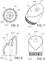
- the first member 2 comprises a first seat 34 (see Figures 7,8 ).
- the first seat 34 involves the first surface 5, at the first through hole 7.
- the first seat 34 houses the first head 28 of the first element 14.
- the second member 3 comprises a second seat 35.
- the second seat 35 affects the second surface 6, at the second through hole 8.
- the second seat 35 houses the second head 31 of the second element 15.
- the first seat 34 and of the second seat 35 which are therefore, essentially, recessed seats, the first surface 5 of the first member 2 and the second surface 6 of the second member 3 match perfectly.
- the first member 2 can comprise a first terminal edge 36, which circumscribes the opening of the first cavity 9.
- the second member 3 can comprise a second edge 37, which circumscribes the second cavity 11.
- threaded connecting members particularly first threaded connecting members 38 and second threaded connecting members 39 ( Figure 2 ).
- first thread 20 of the first element 14 and the second thread 24 of the second element 15 can be effectively used to obtain the connection, respectively, to the upright and to the handrail of the railing, balustrade or the like.
- first threaded connecting members 38 comprise a first bush 40, internally threaded.
- the first bushing 40 is configured to be screwed along the first thread 20 of the first element 14.
- first threaded connecting members 38 comprise a first stud bolt 41.
- the first stud bolt 41 is configured to be screwed inside the first bush 40.
- the first stud bolt 41 in turn, can be coupled directly to a threaded hole provided in the upright of the railing, balustrade, or the like.
- the first stud bolt 41 can be connected to a first terminal core 42, which can be inserted, in turn, in a cavity provided in the handrail.
- the handrail In many railings, balustrades, or the like, the handrail consists of a metal tubular profile, which therefore has, for its conformation, a cavity in which the first terminal core 42 can be inserted.
- the first terminal core 42 comprises a first threaded hole 43, in which the first stud bolt 41 is engageable.
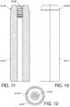
- the first terminal core 42 can be made for example of wood, or other light and easily workable material ( Figures 10-12 ).
- the first terminal core 42 comprises a first shoulder 44, which circumscribes the first threaded hole 43.
- the first member 2 can also include a machined surface suitable for increasing the friction with the internal surface of the handrail, to make the coupling between the two parts more solid ( Figure 5 ).
- an adhesive can also be applied to couple to the internal surface of the handrail.
- the aforementioned second threaded connecting members 39 comprise a second bush 45, internally threaded.
- the second bush 45 is configured to be screwed along the second thread 24 of the second element 15.
- the aforesaid second threaded connecting members 39 comprise a second stud bolt 46.
- the second stud bolt 46 is configured to be screwed inside the second bush 45.
- the second stud bolt 46 in turn, can be directly coupled to a threaded hole provided in the handrail C of the railing, balustrade, or the like.
- the second stud bolt 46 can be connected to a second terminal core 47, which can be inserted, in turn, into a cavity provided in the handrail C.
- the second terminal core 47 can be identical to the first terminal core 42.
- the handrail also consists of a metal tubular profile, which therefore has, for its conformation, a cavity in which the second terminal core 47 can be inserted.
- the second terminal core 47 comprises a second threaded hole 48, in which the second stud bolt 46 is engageable.
- the second terminal core 47 can also be made, for example, of wood or other light and easily workable material ( Figures 10-12 ).
- the second terminal core 47 comprises a second shoulder 49, which circumscribes the second threaded hole 48.
- the second member 3 can also include a machined surface suitable for increasing the friction with the internal surface of the handrail C, to make the coupling between the two parts more solid ( Figure 5 ).
- a gasket for example an o-ring configured to couple to the internal surface of the handrail C can also be mounted.
- the first screw means 18 and the second means screws 19 are temporarily loosened, just enough to allow the detachment of the first surface 5 from the second surface 6, so that the latter can be manually rotated with respect to each other, without however that the second member 3 is released from the first member 2.
- the first element 14 and the second element 15 of the articulated pin 13 can freely rotate, respectively, inside the first through hole 7 and second through hole 8.
- the first screw means 18 and the second screw means 19 are both tightened, so as to bring the first elastic washer 22 into contact with the first abutment surface 10, and the second elastic washer 26 in contact with the second abutment surface 12.
- first terminal core 42 and the second terminal core 47 can also be connected to the joint 1, by means of the first threaded connecting members 38 and the second threaded connecting members 39, respectively, if necessary.
- the connecting means 4 are therefore completely hidden from view, and they are not accessible from the outside.
- the articulated joint 1 according to the present invention has a clean and regular external surface, and therefore improved, from the aesthetic and functional point of view, with respect to known solutions.
- the connecting means 4 once assembled, are completely hidden, the desired installation position can be maintained in a more stable and safe way, without the risk of accidental release.
- articulated joint 1 according to the present invention is decidedly lighter than known solutions, particularly thanks to the fact that the first member 2 and the second member 3 are internally hollow, to house the connecting means 4.
- the surface finish of the first member 2 and of the second member 3 is more responsive to that of the upright and of the handrail, since, being made by casting, they must necessarily be worked externally by means of a satin finishing process.
- the present invention has been described according to preferred embodiments, but equivalent variants can be conceived without departing from the scope of protection offered by the following claims.
Landscapes
- Engineering & Computer Science (AREA)
- General Engineering & Computer Science (AREA)
- Architecture (AREA)
- Mechanical Engineering (AREA)
- Civil Engineering (AREA)
- Structural Engineering (AREA)
- Bridges Or Land Bridges (AREA)
Applications Claiming Priority (1)
| Application Number | Priority Date | Filing Date | Title |
|---|---|---|---|
| IT102019000021120A IT201900021120A1 (it) | 2019-11-13 | 2019-11-13 | Giunto snodabile per balaustre, ringhiere e simili |
Publications (1)
| Publication Number | Publication Date |
|---|---|
| EP3822425A1 true EP3822425A1 (de) | 2021-05-19 |
Family
ID=69903868
Family Applications (1)
| Application Number | Title | Priority Date | Filing Date |
|---|---|---|---|
| EP20206403.6A Withdrawn EP3822425A1 (de) | 2019-11-13 | 2020-11-09 | Gelenkverbindung für balustraden, geländer und ähnliches |
Country Status (2)
| Country | Link |
|---|---|
| EP (1) | EP3822425A1 (de) |
| IT (1) | IT201900021120A1 (de) |
Citations (8)
| Publication number | Priority date | Publication date | Assignee | Title |
|---|---|---|---|---|
| GB2272006A (en) * | 1992-06-25 | 1994-05-04 | Bridon Plc | Joining hand-rail sections. |
| EP0688920A1 (de) * | 1994-06-23 | 1995-12-27 | NEUCON Maschinen- und Bausysteme G.m.b.H. u. Co. Kommanditgesellschaft | Verbindungseinrichtung für einen Treppenhandlauf |
| JPH09125749A (ja) * | 1995-11-02 | 1997-05-13 | Shin Nikkei Co Ltd | 継ぎ手 |
| DE19732363A1 (de) * | 1997-07-28 | 1999-02-18 | Joachim Rueckert | Vorrichtung zum Verbinden zweier Bauteile wie Rohre oder Stangen in einem einstellbaren Winkel |
| JP2003119988A (ja) * | 2001-10-18 | 2003-04-23 | Shuhei Izumi | 手摺連結具 |
| US20030164488A1 (en) * | 2002-03-01 | 2003-09-04 | Terrels Christopher J. | Handrail connection |
| US20040245513A1 (en) * | 2001-10-19 | 2004-12-09 | Shuhei Izumi | Handrail jointer |
| GB2411910A (en) * | 2004-03-09 | 2005-09-14 | Fibrerail Ltd | Modular GRP handrail |
-
2019
- 2019-11-13 IT IT102019000021120A patent/IT201900021120A1/it unknown
-
2020
- 2020-11-09 EP EP20206403.6A patent/EP3822425A1/de not_active Withdrawn
Patent Citations (8)
| Publication number | Priority date | Publication date | Assignee | Title |
|---|---|---|---|---|
| GB2272006A (en) * | 1992-06-25 | 1994-05-04 | Bridon Plc | Joining hand-rail sections. |
| EP0688920A1 (de) * | 1994-06-23 | 1995-12-27 | NEUCON Maschinen- und Bausysteme G.m.b.H. u. Co. Kommanditgesellschaft | Verbindungseinrichtung für einen Treppenhandlauf |
| JPH09125749A (ja) * | 1995-11-02 | 1997-05-13 | Shin Nikkei Co Ltd | 継ぎ手 |
| DE19732363A1 (de) * | 1997-07-28 | 1999-02-18 | Joachim Rueckert | Vorrichtung zum Verbinden zweier Bauteile wie Rohre oder Stangen in einem einstellbaren Winkel |
| JP2003119988A (ja) * | 2001-10-18 | 2003-04-23 | Shuhei Izumi | 手摺連結具 |
| US20040245513A1 (en) * | 2001-10-19 | 2004-12-09 | Shuhei Izumi | Handrail jointer |
| US20030164488A1 (en) * | 2002-03-01 | 2003-09-04 | Terrels Christopher J. | Handrail connection |
| GB2411910A (en) * | 2004-03-09 | 2005-09-14 | Fibrerail Ltd | Modular GRP handrail |
Also Published As
| Publication number | Publication date |
|---|---|
| IT201900021120A1 (it) | 2021-05-13 |
Similar Documents
| Publication | Publication Date | Title |
|---|---|---|
| US7044450B2 (en) | Quick rail system with adjustable support | |
| CA2499684C (en) | Wire rope connectors and tensioners for deck railing systems | |
| US7909311B2 (en) | Adjustable baluster | |
| US20080277640A1 (en) | Rail and ramp systems with adjustable fittings | |
| US20070246698A1 (en) | Baluster ball joint adapter attachment for a baluster to stair rail(s) and base | |
| EP0688920B1 (de) | Verbindungseinrichtung für einen Treppenhandlauf | |
| US6860472B2 (en) | Quick rail system | |
| US20080179476A1 (en) | Universal Rail Mounting Bracket | |
| JP2011202363A (ja) | 梯子 | |
| CA2687925C (en) | Extendable baluster assembly | |
| EP0651112B1 (de) | Modulaires Geländer mit horizontalen oder geneigten Holmen | |
| EP2021571B1 (de) | Verbesserungen an und in bezug auf sicherheitstore | |
| EP2902566B1 (de) | Pfosten für Balustraden, Geländer und ähnliche | |
| KR101978360B1 (ko) | 개량형 난간의 결합구조 | |
| KR101099637B1 (ko) | 핸드레일 서포트어셈블리 | |
| EP2746486A2 (de) | Ständer für Rampen, Balustraden und dergleichen | |
| US7104742B1 (en) | Straight-aligning rail system | |
| DE20021827U1 (de) | Geländervorrichtung für gegen Absturz zu sichernde Konstruktionen und Geländerpfosteneinrichtung hierfür | |
| KR101425590B1 (ko) | 각도 조절이 가능한 계단 및 그 시공방법 | |
| US20120012802A1 (en) | Rail Assembly Having a Baluster Swing Bracket | |
| KR200378350Y1 (ko) | 난간 설치용 수직바 연결부재 | |
| CN117822868B (zh) | 一种踏步管连接件及其安装方法 | |
| KR200395591Y1 (ko) | 각도 조절이 가능한 계단 | |
| EP4244442A1 (de) | Pfosten für eine schutzbarriere des leitplanken-, balustraden- oder ähnlichen typs und solch eine schutzbarriere mit mindestens zwei besagten pfosten | |
| IT201800004095A1 (it) | Profilato per la connessione di pannellature ad un componente edilizio e per la registrazione della sua inclinazione |
Legal Events
| Date | Code | Title | Description |
|---|---|---|---|
| PUAI | Public reference made under article 153(3) epc to a published international application that has entered the european phase |
Free format text: ORIGINAL CODE: 0009012 |
|
| STAA | Information on the status of an ep patent application or granted ep patent |
Free format text: STATUS: THE APPLICATION HAS BEEN PUBLISHED |
|
| AK | Designated contracting states |
Kind code of ref document: A1 Designated state(s): AL AT BE BG CH CY CZ DE DK EE ES FI FR GB GR HR HU IE IS IT LI LT LU LV MC MK MT NL NO PL PT RO RS SE SI SK SM TR |
|
| STAA | Information on the status of an ep patent application or granted ep patent |
Free format text: STATUS: THE APPLICATION IS DEEMED TO BE WITHDRAWN |
|
| 18D | Application deemed to be withdrawn |
Effective date: 20211120 |